WO2014106901A1 - 空気調和装置 - Google Patents
空気調和装置 Download PDFInfo
- Publication number
- WO2014106901A1 WO2014106901A1 PCT/JP2013/050037 JP2013050037W WO2014106901A1 WO 2014106901 A1 WO2014106901 A1 WO 2014106901A1 JP 2013050037 W JP2013050037 W JP 2013050037W WO 2014106901 A1 WO2014106901 A1 WO 2014106901A1
- Authority
- WO
- WIPO (PCT)
- Prior art keywords
- valve
- indoor
- control device
- refrigerant
- branch
- Prior art date
- Legal status (The legal status is an assumption and is not a legal conclusion. Google has not performed a legal analysis and makes no representation as to the accuracy of the status listed.)
- Ceased
Links
Images




Classifications
-
- F—MECHANICAL ENGINEERING; LIGHTING; HEATING; WEAPONS; BLASTING
- F25—REFRIGERATION OR COOLING; COMBINED HEATING AND REFRIGERATION SYSTEMS; HEAT PUMP SYSTEMS; MANUFACTURE OR STORAGE OF ICE; LIQUEFACTION SOLIDIFICATION OF GASES
- F25B—REFRIGERATION MACHINES, PLANTS OR SYSTEMS; COMBINED HEATING AND REFRIGERATION SYSTEMS; HEAT PUMP SYSTEMS
- F25B13/00—Compression machines, plants or systems, with reversible cycle
-
- F—MECHANICAL ENGINEERING; LIGHTING; HEATING; WEAPONS; BLASTING
- F25—REFRIGERATION OR COOLING; COMBINED HEATING AND REFRIGERATION SYSTEMS; HEAT PUMP SYSTEMS; MANUFACTURE OR STORAGE OF ICE; LIQUEFACTION SOLIDIFICATION OF GASES
- F25B—REFRIGERATION MACHINES, PLANTS OR SYSTEMS; COMBINED HEATING AND REFRIGERATION SYSTEMS; HEAT PUMP SYSTEMS
- F25B2313/00—Compression machines, plants or systems with reversible cycle not otherwise provided for
- F25B2313/006—Compression machines, plants or systems with reversible cycle not otherwise provided for two pipes connecting the outdoor side to the indoor side with multiple indoor units
-
- F—MECHANICAL ENGINEERING; LIGHTING; HEATING; WEAPONS; BLASTING
- F25—REFRIGERATION OR COOLING; COMBINED HEATING AND REFRIGERATION SYSTEMS; HEAT PUMP SYSTEMS; MANUFACTURE OR STORAGE OF ICE; LIQUEFACTION SOLIDIFICATION OF GASES
- F25B—REFRIGERATION MACHINES, PLANTS OR SYSTEMS; COMBINED HEATING AND REFRIGERATION SYSTEMS; HEAT PUMP SYSTEMS
- F25B2313/00—Compression machines, plants or systems with reversible cycle not otherwise provided for
- F25B2313/023—Compression machines, plants or systems with reversible cycle not otherwise provided for using multiple indoor units
- F25B2313/0231—Compression machines, plants or systems with reversible cycle not otherwise provided for using multiple indoor units with simultaneous cooling and heating
-
- F—MECHANICAL ENGINEERING; LIGHTING; HEATING; WEAPONS; BLASTING
- F25—REFRIGERATION OR COOLING; COMBINED HEATING AND REFRIGERATION SYSTEMS; HEAT PUMP SYSTEMS; MANUFACTURE OR STORAGE OF ICE; LIQUEFACTION SOLIDIFICATION OF GASES
- F25B—REFRIGERATION MACHINES, PLANTS OR SYSTEMS; COMBINED HEATING AND REFRIGERATION SYSTEMS; HEAT PUMP SYSTEMS
- F25B2313/00—Compression machines, plants or systems with reversible cycle not otherwise provided for
- F25B2313/023—Compression machines, plants or systems with reversible cycle not otherwise provided for using multiple indoor units
- F25B2313/0233—Compression machines, plants or systems with reversible cycle not otherwise provided for using multiple indoor units in parallel arrangements
-
- F—MECHANICAL ENGINEERING; LIGHTING; HEATING; WEAPONS; BLASTING
- F25—REFRIGERATION OR COOLING; COMBINED HEATING AND REFRIGERATION SYSTEMS; HEAT PUMP SYSTEMS; MANUFACTURE OR STORAGE OF ICE; LIQUEFACTION SOLIDIFICATION OF GASES
- F25B—REFRIGERATION MACHINES, PLANTS OR SYSTEMS; COMBINED HEATING AND REFRIGERATION SYSTEMS; HEAT PUMP SYSTEMS
- F25B2313/00—Compression machines, plants or systems with reversible cycle not otherwise provided for
- F25B2313/025—Compression machines, plants or systems with reversible cycle not otherwise provided for using multiple outdoor units
- F25B2313/0253—Compression machines, plants or systems with reversible cycle not otherwise provided for using multiple outdoor units in parallel arrangements
-
- F—MECHANICAL ENGINEERING; LIGHTING; HEATING; WEAPONS; BLASTING
- F25—REFRIGERATION OR COOLING; COMBINED HEATING AND REFRIGERATION SYSTEMS; HEAT PUMP SYSTEMS; MANUFACTURE OR STORAGE OF ICE; LIQUEFACTION SOLIDIFICATION OF GASES
- F25B—REFRIGERATION MACHINES, PLANTS OR SYSTEMS; COMBINED HEATING AND REFRIGERATION SYSTEMS; HEAT PUMP SYSTEMS
- F25B2313/00—Compression machines, plants or systems with reversible cycle not otherwise provided for
- F25B2313/027—Compression machines, plants or systems with reversible cycle not otherwise provided for characterised by the reversing means
- F25B2313/02741—Compression machines, plants or systems with reversible cycle not otherwise provided for characterised by the reversing means using one four-way valve
Definitions
- the present invention is applied to, for example, a building multi-air conditioner equipped with a refrigerant circuit and a structure capable of efficiently supplying hot and cold produced by a heat source machine, or both hot and cold to a plurality of loads.
- the present invention relates to an air conditioner used.
- an air conditioner such as a multi air conditioner for buildings
- a cooling operation or a heating operation is performed by circulating a refrigerant between an outdoor unit that is a heat source unit arranged outdoors and an indoor unit arranged indoors.
- the air-conditioning target space is cooled or heated by air cooled by heat absorbed by the refrigerant or air heated by heat released from the refrigerant.
- a refrigerant used in such an air conditioner for example, an HFC (hydrofluorocarbon) refrigerant is often used.
- a natural refrigerant such as carbon dioxide (CO 2 ) has been proposed.
- an air conditioner that connects a heat source unit and a plurality of indoor units and supplies a refrigerant from the heat source unit to the plurality of indoor units to enable a cooling / heating operation
- Patent Document 1 three-way connection is made to the first connection pipe (6b, 6c, 6d) and the first connection pipe (6) or the second connection pipe (7) in a switchable manner.
- the first branch portion (10) including the switching valve (8), the second connection pipe (7b, 7c, 7d) on the indoor unit side, and the second connection pipe (7) are connected to the check valve (50b, 50c, 50d, 52b, 52c, 52d), and a second branch portion (11) connected thereto.
- connection port 8a first port 8a side connection piping
- second port 8b second port 8b
- third port 8c second connection port
- the refrigerant is controlled by the amount of superheat at the outlet of the indoor heat exchanger (5), and the first connection pipe (6b, 6c, 6d) on the indoor unit side is in a low-pressure gas state. Refrigerant is flowing.
- the refrigerant When the indoor unit performs heating operation, the refrigerant has a low pressure in the first connection pipe (6) and a high pressure in the second connection pipe (7).
- One connection port (first port 8a) side connection piping is high pressure
- the other connection port (second port 8b) side connection piping is low pressure
- another connection port (third port 8c) side connection The piping is in a high pressure state.
- the refrigerant is controlled by the outlet subcooling amount of the indoor heat exchanger (5), and the first connection pipes (6b, 6c, 6d) on the indoor unit side are in a high-temperature and high-pressure gas state.
- the refrigerant is flowing, and high-temperature and high-pressure liquid refrigerant exists in the indoor heat exchanger (5) and the connection pipe from the indoor heat exchanger (5) to the first flow control device (9).
- the high-temperature high-pressure gas refrigerant and the high-temperature high-pressure liquid refrigerant that have flowed during the heating pass through the three-way switching valve (8) and are in a low-pressure state. Will flow into the first connection pipe (6).
- the three-way switching valve (8) When the operation of the connected indoor unit is switched from the heating operation to the cooling operation, the three-way switching valve (8) generates a refrigerant flow sound due to the balance between the high pressure and the low pressure of the refrigerant passing through the three-way switching valve (8). In particular, the flow noise of the high-temperature high-pressure liquid refrigerant is increased.
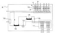
- FIG. 11 There is another air conditioner that uses a solenoid valve (electromagnetic on-off valve) instead of the three-way switching valve (8) so as to be compact (see FIG. 11).
- the second electromagnetic valve b is used for heating, and the first electromagnetic valve a, the third electromagnetic valve c, and the orifice d are used for cooling. That is, in the air conditioner shown in FIG. 11, in order to reduce the flow noise of the high-temperature high-pressure liquid refrigerant when switching to the cooling operation, the orifice d, the third electromagnetic valve c, and the first electromagnetic valve a are stepped. The refrigerant was allowed to flow.
- symbol is attached
- Japanese Patent No. 4350836 (Embodiment 1, FIG. 1, etc.)
- Japanese Patent Laid-Open No. 09-0428804 Japanese Patent Laid-Open No. 09-0428804 (FIG. 1 etc.)
- the present invention has been made to solve the above-described problems, and an object of the present invention is to provide an air conditioner that is compact and can be improved in maintainability while maintaining quietness.
- An air conditioner includes a heat source unit having a compressor, a switching valve and a heat source unit side heat exchanger, and a plurality of indoor units each having an indoor side heat exchanger and an indoor side flow rate control unit.
- 1 is an air conditioner that is connected via a connection pipe and a second connection pipe, supplies a refrigerant from the heat source unit to the plurality of indoor units, and performs a cooling / heating operation, each of the plurality of indoor units
- a first branch section that switches and connects one of the indoor heat exchangers to the first connection pipe or the second connection pipe, one side is connected to the second connection pipe, and the other side is plural
- a second branch unit that is branched and connected to the other of the indoor heat exchangers of each of the plurality of indoor units via the indoor flow rate control device,
- the first branching section is duplicated from the first connecting pipe side.
- a branch-side flow rate control device provided in each of the pipes branched to the indoor-side heat exchangers, and the branch-side flow rate control devices and the indoor-side heat exchangers connected to each other. And a solenoid valve provided in each pipe branched from the pipe being provided.
- the air conditioner according to the present invention includes the valve device that combines the branch flow rate control device and the electromagnetic valve, the air conditioner can be compact and improve maintainability.
- FIG. 1 is an overall configuration diagram centering on a refrigerant system of an air-conditioning apparatus 100 according to an embodiment of the present invention.
- 2 to 5 show the operating state of the air conditioner 100 during the cooling / heating operation.
- 2 is an operation state diagram of only cooling operation
- FIG. 3 is an operation state diagram of only heating operation
- FIG. 4 is an operation state diagram of cooling main operation in which the cooling operation capacity of the simultaneous cooling and heating operation is larger than the heating operation capacity.
- FIG. 5 shows an operation state diagram of the heating main operation in which the heating operation capacity of the simultaneous cooling and heating operation is larger than the cooling operation capacity.
- a case where three indoor units are connected to one heat source unit will be described, but the same applies to the case where two or more indoor units are connected.
- an air conditioner 100 is configured by connecting a heat source unit A, indoor units B, C, and D (hereinafter simply referred to as indoor units unless otherwise noted) and a relay unit E.
- the heat source unit A has a function of supplying hot or cold heat to the indoor unit.
- the indoor units are connected in parallel to each other and have the same configuration.
- the indoor unit has a function of executing air conditioning of an air-conditioning target space such as a room by using heat or cold supplied from the heat source unit A.
- the relay unit E is interposed between the heat source unit A and the indoor unit, and has a function of switching the flow of the refrigerant supplied from the heat source unit A in response to a request from the indoor unit.
- the heat source machine A includes a compressor 1 having a variable capacity, a four-way switching valve 2 that switches the refrigerant flow direction in the heat source machine A, a heat source machine-side heat exchanger 3 that functions as an evaporator or a condenser (heat radiator), and a four-way switching valve. 2, an accumulator 4 connected to the suction side of the compressor 1, a heat source side blower 20 with variable air flow for blowing air to the heat source side heat exchanger 3, and heat source side switching for restricting the refrigerant flow direction A valve 40 is provided. And the heat source machine A is comprised by these.
- the four-way switching valve 2 corresponds to the “switching valve” of the present invention. However, the “switching valve” may be configured by combining a two-way valve, a three-way valve, or the like instead of the four-way switching valve.
- the indoor unit is an indoor heat exchanger 5 that functions as a condenser (radiator) or an evaporator, the amount of superheat on the outlet side of the indoor heat exchanger 5 during cooling, and the indoor heat exchanger 5 during heating.
- the first flow rate control device (indoor flow rate control device) 9 controlled by the amount of subcooling on the outlet side of the vehicle is provided. And these constitute an indoor unit.
- the relay E includes a first branching unit 10, a second flow rate control device 13, a second branching unit 11, a gas-liquid separator 12, a heat exchange unit (a first heat exchange unit 19, a second heat exchange unit). Part 16) and a third flow rate control device 15 are incorporated. And the repeater E is comprised by these.
- the four-way switching valve 2 of the heat source machine A and the relay machine E are connected by a thick first connection pipe 6.
- the indoor unit heat exchanger 5 and the relay unit E of the indoor unit are connected to each of the first connection pipes 6b, 6c, and 6d on the indoor unit side corresponding to the first connection pipe 6.
- the heat source machine side heat exchanger 3 of the heat source machine A and the relay machine E are connected by a second connection pipe 7 that is narrower than the first connection pipe 6.
- the indoor side heat exchanger 5 and the relay unit E of the indoor unit are connected via the first connection pipe 6 and the second connection pipes 7b and 7c on the indoor unit side corresponding to the second connection pipe 7 are connected. , 7d.
- the 1st branch part 10 has the function to connect the 1st connection piping 6b, 6c, 6d by the side of an indoor unit, and the 1st connection piping 6 or the 2nd connection piping 7 side so that switching is possible.
- the first branch portion 10 includes a fourth flow rate control device (branch side flow rate control device) connected to the first connection piping 6b, 6c, 6d on the indoor unit side and the first connection piping 6. ) 55 and the solenoid valve 31 as a valve device connected to the first connection piping 6b, 6c, 6d on the indoor unit side and the first connection piping 6 side is mounted.
- the second branch portion 11 has a function of switching the connection between the second connection pipes 7b, 7c and 7d on the indoor unit side and the second connection pipe 7 according to the flow of the refrigerant.
- the second branch portion 11 includes a first check valve 50 (first check valves 50b, 50c, and 50d), which will be described later, and a second check valve 52 (second check valve, which will be described later). 52b, 52c, 52d) are mounted.
- the gas-liquid separator 12 is provided in the middle of the second connection pipe 7, the gas phase portion is connected to the electromagnetic valve 31 of the first branch portion 10, and the liquid phase portion is connected to the second branch portion 11. It is connected.
- the second flow rate control device 13 is provided between the gas-liquid separation device 12 of the second connection pipe 7 and the second branch portion 11, and is configured by, for example, an electric expansion valve that can be opened and closed. Yes. Note that the second branch portion 11 and the first connection pipe 6 are connected by a first bypass pipe 14.
- the 3rd flow control device 15 is provided in the middle of the 1st bypass piping 14, and is constituted by an electric expansion valve etc. which can be opened and closed, for example.
- the second heat exchange unit 16 is provided downstream of the third flow rate control device 15 of the first bypass pipe 14 and between the second connection pipe 7 and a portion downstream of the second flow rate control device 13. In each case, heat exchange is performed.
- the first heat exchanging part 19 is provided downstream of the second heat exchanging part 16 of the first bypass pipe 14, and between the part of the second connecting pipe 7 upstream of the second flow rate control device 13. In each case, heat exchange is performed.
- the first check valves 50b, 50c, and 50d are provided in the middle of the second connection pipes 7b, 7c, and 7d on the indoor unit side of the second branch portion 11, respectively. Refrigerant flow is allowed only to the second connection pipes 7b, 7c, 7d on the indoor unit side.
- the second bypass pipe 51 is connected to the upstream pipe section of the second heat exchange section 16. And the pipes connected to the second connection pipes 7b, 7c, 7d on the indoor unit side in the second bypass pipe 51 and the pipes connected to the second connection pipe 7 in the second bypass pipe 51 are in the middle. Join.
- the second check valves 52 b, 52 c, 52 d are connected to the second connection pipes 7 b, 7 c, 7 d on the indoor unit side in the middle of the second bypass pipe 51. 2 is provided upstream of the portion joining the pipe connected to the connection pipe 7 and permits the refrigerant to flow only from the second connection pipe 7b, 7c, 7d on the indoor unit side to the second connection pipe 7. . In addition, it reaches the first flow control device 9 from the second connection pipe 7 via the second connection pipes 7b, 7c, 7d on the indoor unit side where the first check valves 50b, 50c, 50d are provided.
- the flow path constitutes a first refrigerant flow path
- second connection pipes 7b, 7c, 7d and second check valves 52b, 52c, 52d on the indoor unit side are provided from the first flow control device 9.
- the flow path reaching the second connection pipe 7 via the second bypass pipe 51 constitutes the second refrigerant flow path.
- the third check valve 32 is provided in the middle of the pipe connecting the heat source apparatus side heat exchanger 3 and the second connection pipe 7, and only from the heat source apparatus side heat exchanger 3 to the second connection pipe 7. Allow refrigerant flow.
- the fourth check valve 33 is provided in the middle of the pipe connecting the four-way switching valve 2 of the heat source apparatus A and the first connection pipe 6, and the refrigerant flows only from the first connection pipe 6 to the four-way switching valve 2. Is acceptable.
- the fifth check valve 34 is provided in the middle of the pipe connecting the four-way switching valve 2 and the second connection pipe 7 of the heat source machine A, and the refrigerant flows only from the four-way switching valve 2 to the second connection pipe 7. Is acceptable.
- the sixth check valve 35 is provided in the middle of the pipe connecting the heat source apparatus side heat exchanger 3 and the first connection pipe 6, and only from the first connection pipe 6 to the heat source apparatus side heat exchanger 3. Allow refrigerant flow.
- the third check valve 32, the fourth check valve 33, the fifth check valve 34, and the sixth check valve 35 constitute a heat source machine side switching valve 40.
- the relay machine E is provided with a first pressure detecting means 25, a second pressure detecting means 26, and a third pressure detecting means 56.
- the first pressure detection means 25 is provided between the first branch portion 10 of the second connection pipe 7 and the second flow rate control device 13.
- the second pressure detection means 26 is provided between the second flow control device 13 and the first flow control device 9.
- the third pressure detection means 56 is provided at a connection position between the first connection pipe 6 and the first bypass pipe 14.
- the indoor unit is provided with first temperature detection means 53 and second temperature detection means 54.
- the 1st temperature detection means 53 is provided in the 1st branch part 10 side of an indoor unit.
- the 2nd temperature detection means 54 is provided in the 2nd branch part 11 side of an indoor unit. That is, the first temperature detection means 53 and the second temperature detection means 54 are provided at both ends of the indoor heat exchanger 5 and connected to the first flow control device 9 side is the second temperature detection.
- the first temperature detecting means 53 is connected to the means 54 and the other end.
- the heat source machine side heat exchanger 3 includes a first heat source machine side heat exchanger 41 and a second heat source machine side heat exchanger 42, a heat source machine side bypass passage 43, a first electromagnetic on-off valve 44, a second The electromagnetic on-off valve 45, the third electromagnetic on-off valve 46, the fourth electromagnetic on-off valve 47, and the fifth electromagnetic on-off valve 48 are configured.
- the heat source device side heat exchanger 3 is provided with a heat source device side blower 20 that controls the heat exchange capacity of the heat source device side heat exchanger 3.
- the first heat source device side heat exchanger 41 and the second heat source device side heat exchanger 42 have the same heat transfer area and are connected in parallel to each other.
- the heat source unit side bypass passage 43 is connected in parallel to the first heat source unit side heat exchanger 41 and the second heat source unit side heat exchanger 42.
- the first electromagnetic on-off valve 44 is provided at one end of the first heat source unit side heat exchanger 41 on the side connected to the four-way switching valve 2.
- the second electromagnetic opening / closing valve 45 is provided at the other end of the first heat source unit side heat exchanger 41.
- the third electromagnetic opening / closing valve 46 is provided at one end of the second heat source unit side heat exchanger 42 on the side connected to the four-way switching valve 2.
- the fourth electromagnetic opening / closing valve 47 is provided at the other end of the second heat source unit side heat exchanger 42.
- the fifth electromagnetic opening / closing valve 48 is provided in the middle of the heat source unit side bypass path 43.
- the heat source machine A is provided with fourth pressure detecting means 18.
- the fourth pressure detection means 18 is provided in the middle of the pipe connecting the four-way switching valve 2 and the discharge part of the compressor 1.
- the air conditioner 100 has a control device 70.
- the control device 70 performs overall control of the entire system of the air conditioner 100. Specifically, the control device 70 controls the drive frequency of the compressor 1, the number of rotations of the blower provided in the heat source fan blower 20 and the indoor heat exchanger 5, switching of the four-way switching valve 2, and switching of each solenoid valve. Controls opening and closing, opening of each throttle device, and the like. That is, the control device 70 is based on the detection information from the temperature detection means and pressure detection means described above and instructions from the remote controller (not shown), and the actuators (compressor 1, four-way switching valve 2, solenoid valves (first solenoid valve)). 1 electromagnetic on-off valve 44 to fifth electromagnetic on-off valve 48, solenoid valve 31), each throttle device (first flow control device 9, second flow control device 13, third flow control device 15, fourth Driving components such as the flow rate control device 55).
- refrigerant to be filled in the air conditioner 100 for example, carbon dioxide (CO 2) and hydrocarbons, natural refrigerant such as helium, HFC410A and HFC407C (HFC of R32 / R125 / R134a Is a non-azeotropic refrigerant mixture mixed at a ratio of 23/25/52 wt%), an alternative refrigerant not containing chlorine such as HFC404A, or a fluorocarbon refrigerant such as R22 and R134a used in existing products May be used.
- CO 2 carbon dioxide
- hydrocarbons natural refrigerant such as helium, HFC410A and HFC407C (HFC of R32 / R125 / R134a Is a non-azeotropic refrigerant mixture mixed at a ratio of 23/25/52 wt%)
- an alternative refrigerant not containing chlorine such as HFC404A
- a fluorocarbon refrigerant such as R22 and R134a used in existing
- heat source apparatus side heat exchanger 3 and the indoor side heat exchanger 5 exchange heat between the refrigerant and the air
- a heat medium other than the refrigerant and the air for example, water or brine It is also possible to perform heat exchange with the above.
- the one heat source apparatus A is mounted in the air conditioning apparatus 100 is shown as an example, it is not limited to this, Two or more heat source apparatuses A are mounted. It may be. Furthermore, although the case where three indoor units are mounted is shown as an example, the present invention is not limited to this, and four or more indoor units may be mounted.
- the control device 70 may be mounted on any one of the heat source unit A, the indoor unit, and the relay unit E, or may be mounted on all of them. Further, the control device 70 may be mounted separately from the heat source unit A, the indoor unit, and the relay unit E. When a plurality of control devices 70 are configured, they may be connected so that they can communicate with each other wirelessly or by wire.
- the high-temperature and high-pressure refrigerant gas discharged from the compressor 1 passes through the four-way switching valve 2, and air blown by the heat source machine side blower 20 whose air flow rate is variable in the heat source machine side heat exchanger 3. It is condensed and liquefied by heat exchange.
- the refrigerant then passes through the third check valve 32, the second connection pipe 7, the gas-liquid separation device 12, and the second flow rate control device 13 in this order, and further to the second branch portion 11 and the indoor unit side. It passes through the second connection pipes 7b, 7c, 7d and flows into the indoor units B, C, D.
- the refrigerant flowing into the indoor units B, C, and D is depressurized to a low pressure by the first flow rate control device 9 that is controlled by the superheat amount at the outlet of each indoor heat exchanger 5.
- the decompressed refrigerant flows into the indoor heat exchanger 5, exchanges heat with indoor air in the indoor heat exchanger 5, evaporates and gasifies, and cools the room.
- coolant used as this gas state is the 1st connection piping 6b, 6c, 6d by the side of an indoor unit, the 4th flow control apparatus 55 of the 1st branch part 10, the 1st connection piping 6, 4th.
- the check valve 33, the four-way switching valve 2 of the heat source unit, and the accumulator 4 are sucked into the compressor 1. In this way, the circulation cycle is configured and the cooling operation is performed.
- each solenoid valve 31 is controlled to be closed. Since the first connection pipe 6 is at a low pressure and the second connection pipe 7 is at a high pressure, the refrigerant inevitably flows to the third check valve 32 and the fourth check valve 33. Further, the opening degree of the fourth flow control device 55 is controlled based on the state of the refrigerant obtained by the detection information from the third pressure detection means 56.
- part of the refrigerant that has passed through the second flow rate control device 13 enters the first bypass pipe 14. Then, after the pressure is reduced to a low pressure by the third flow control device 15, the refrigerant that has passed through the second flow control device 13 in the second heat exchange unit 16 (the refrigerant before branching to the first bypass pipe 14). Evaporate by exchanging heat with each other. Further, the first heat exchange unit 19 evaporates by exchanging heat with the refrigerant before flowing into the second flow rate control device 13. The evaporated refrigerant enters the first connection pipe 6 and the fourth check valve 33 and is sucked into the compressor 1 through the four-way switching valve 2 of the heat source unit and the accumulator 4.
- the capacity of the compressor 1 having a variable capacity and the air flow rate of the heat source unit side fan 20 are adjusted so that the evaporation temperature of the indoor unit and the condensation temperature of the heat source unit side heat exchanger 3 become a predetermined target temperature. In each indoor unit, the target cooling capacity can be obtained.
- the condensation temperature of the heat source device side heat exchanger 3 is obtained as the saturation temperature of the pressure detected by the fourth pressure detection means 18.
- FIG. 3 shows an example in which the heating operation is performed for all of the indoor units B, C, and D.
- the high-temperature and high-pressure refrigerant gas discharged from the compressor 1 passes through the four-way switching valve 2, the fifth check valve 34, the second connection pipe 7, the gas-liquid separator 12, the first It flows into the indoor units B, C, D through the solenoid valve 31 of the branching section 10 and the first connection pipes 6b, 6c, 6d on the indoor unit side in this order.
- the refrigerant that has flowed into the indoor units B, C, and D exchanges heat with room air to be condensed and liquefied to heat the room.
- the refrigerant in this state is controlled by the outlet subcooling amount of each indoor heat exchanger 5 and passes through the first flow rate control device 9.
- the refrigerant that has passed through the first flow control device 9 flows into the second branch portion 11 from the second connection pipes 7b, 7c, 7d on the indoor unit side, and passes through the second check valves 52b, 52c, 52d. Merge after passing.
- the refrigerant merged at the second branch portion 11 is further guided between the second flow control device 13 and the second heat exchange portion 16 in the middle of the second connection pipe 7, and the third flow control device 15. Pass through.
- the refrigerant is decompressed to a low pressure gas-liquid two-phase by the first flow control device 9 or the third flow control device 15 here.
- the refrigerant depressurized to a low pressure flows into the sixth check valve 35 of the heat source unit A and the heat source unit side heat exchanger 3 through the first connection pipe 6, where the air flow rate variable heat source unit side It evaporates by exchanging heat with the air blown by the blower 20.
- the refrigerant that has been evaporated and turned into a gas state is sucked into the compressor 1 through the four-way switching valve 2 and the accumulator 4. In this way, a circulation cycle is configured and heating operation is performed.
- each solenoid valve 31 is controlled to be opened.
- the fourth flow control device 55 is closed.
- the refrigerant since the first connection pipe 6 is low pressure and the second connection pipe 7 is high pressure, the refrigerant inevitably has a fifth check valve 34 and a sixth check valve 35. Circulate to The first check valves 50b, 50c, and 50d are closed because the second connection pipes 7b, 7c, and 7d on the indoor unit side have a higher pressure than the second connection pipe 7.
- the capacity of the compressor 1 having a variable capacity and the amount of air blown from the heat source side blower 20 are adjusted so that the condensation temperature of the indoor unit and the evaporation temperature of the heat source side heat exchanger 3 become a predetermined target temperature. In each indoor unit, the target heating capacity can be obtained.
- FIG. 4 shows an example of a cooling main operation when there is a cooling request from the indoor units B and C and a heating request from the indoor unit D.
- the high-temperature and high-pressure refrigerant gas discharged from the compressor 1 flows into the heat source machine side heat exchanger 3 through the four-way switching valve 2, and is blown by the heat source machine side blower 20 with variable air flow here. Heat-exchanged with the air to be brought into a two-phase high temperature and high pressure state.
- the capacity of the compressor 1 having a variable capacity and the amount of air blown from the heat source side fan 20 are adjusted so that the evaporation temperature and the condensation temperature of the indoor unit become a predetermined target temperature.
- the fourth electromagnetic switching valve 47 is opened and closed to adjust the heat transfer area.
- circulates the 1st heat source machine side heat exchanger 41 and the 2nd heat source machine side heat exchanger 42 is adjusted by opening and closing the 5th electromagnetic on-off valve 48 of the heat source machine side bypass path 43.
- the two-phase high-temperature and high-pressure refrigerant passes through the third check valve 32 and the second connection pipe 7 and is sent to the gas-liquid separator 12 of the relay E, where the gas-state refrigerant and the liquid-state refrigerant are sent. And separated. Then, the gaseous refrigerant separated by the gas-liquid separator 12 flows into the indoor unit D to be heated through the electromagnetic valve 31 of the first branch portion 10 and the first connection pipe 6d on the indoor unit side in this order. Then, the indoor heat exchanger 5 exchanges heat with room air to condense and heat the room.
- the refrigerant that has flowed out of the indoor heat exchanger 5 passes through the first flow rate control device 9 controlled by the outlet subcooling amount of the indoor heat exchanger 5 of the indoor unit D, and is slightly depressurized to be the second branch. Flows into the section 11. This refrigerant flows through the second bypass pipe 51 including the second check valve 52d into the downstream portion of the second flow control device 13 of the second connection pipe 7.
- the liquid refrigerant separated by the gas-liquid separator 12 passes through the second flow rate controller 13 controlled by the detected pressure of the first pressure detector 25 and the detected pressure of the second pressure detector 26.
- the refrigerant passes through the indoor unit D to be heated. Thereafter, it flows into the second heat exchange unit 16 and is cooled by the second heat exchange unit 16.
- a part of the refrigerant cooled by the second heat exchange unit 16 passes through the first check valves 50b and 50c and the second connection pipes 7b and 7c on the indoor unit side to be cooled.
- the refrigerant that has flowed into the indoor units B and C enters the first flow control device 9 controlled by the superheat amount at the outlet of the indoor heat exchanger 5 of each of the indoor units B and C, and is then depressurized. It enters into the heat exchanger 5 and exchanges heat to evaporate into a gas state to cool the room. Thereafter, it flows into the first connection pipe 6 via the fourth flow rate control device 55.
- the remainder of the refrigerant cooled by the second heat exchange unit 16 is controlled so that the pressure difference between the detected pressure of the first pressure detecting means 25 and the detected pressure of the second pressure detecting means 26 falls within a predetermined range.
- the third flow control device 15 is passed through. Then, after heat-exchanging and evaporating in the 2nd heat exchange part 16 and the 1st heat exchange part 19, it flows into the thick 1st connection piping 6, and merges with the refrigerant
- the refrigerant merged in the first connection pipe 6 is sucked into the compressor 1 through the fourth check valve 33, the four-way switching valve 2, and the accumulator 4 of the heat source machine A. In this way, the circulation cycle is configured and the cooling main operation is performed.
- the solenoid valve 31 connected to the indoor units B and C is controlled to be closed, and the solenoid valve 31 connected to the indoor unit D is controlled to be opened. Further, the fourth flow rate control device 55 connected to the indoor units B and C is opened, and the fourth flow rate control device 55 connected to the indoor unit D is closed.
- the refrigerant since the first connection pipe 6 is low pressure and the second connection pipe 7 is high pressure, the refrigerant inevitably flows into the third check valve 32 and the fourth check valve 33. Furthermore, since the second connecting pipes 7b and 7c on the indoor unit side are lower in pressure than the second connecting pipe 7, the second check valves 52b and 52c are closed. Moreover, since the pressure of the second connection pipe 7d on the indoor unit side is higher than that of the second connection pipe 7, the first check valve 50d is closed. By the first check valve 50 and the second check valve 52, the cooling request is made in a state where the refrigerant that has passed through the indoor unit D that requires heating does not pass through the second heat exchanging unit 16 and does not have sufficient subcooling. Is prevented from flowing into the indoor units B and C.
- FIG. 5 shows an example of a heating main operation when there is a heating request from the indoor units B and C and a cooling request from the indoor unit D.
- the high-temperature and high-pressure refrigerant gas discharged from the compressor 1 is sent to the relay machine E through the four-way switching valve 2, the fifth check valve 34, and the second connection pipe 7, as shown in FIG. It passes through the liquid separator 12.
- the refrigerant that has passed through the gas-liquid separator 12 passes through the electromagnetic valve 31 of the first branching section 10 and the first connection pipes 6b and 6c on the indoor unit side, and then flows into the indoor units B and C to be heated. Then, heat is exchanged with room air in the indoor heat exchanger 5 to be condensed and heated to heat the room.
- the condensed and liquefied refrigerant is controlled by the outlet subcooling amount of each indoor side heat exchanger 5 of the indoor units C and D, passes through the first flow control device 9, is slightly decompressed, and flows into the second branch portion 11. To do.
- the refrigerant that has flowed into the second branch section 11 joins the second connection pipe 7 through the second bypass pipe including the second check valves 52b and 52c, and is cooled by the second heat exchange section 16. Is done. A part of the refrigerant cooled by the second heat exchange unit 16 passes through the first check valve 50d and the second connection pipe 7d on the indoor unit side and enters the indoor unit D to be cooled.
- the refrigerant that has entered the indoor unit D enters the first flow rate control device 9 controlled by the outlet superheat amount of the indoor side heat exchanger 5 and is depressurized, and then enters the indoor side heat exchanger 5 and heats it. It exchanges and evaporates, becomes a gas state, cools the room, and flows into the first connection pipe 6 via the fourth flow rate control device 55.
- the remainder of the refrigerant cooled by the second heat exchange unit 16 is set so that the pressure difference between the detection pressure of the first pressure detection unit 25 and the detection pressure of the second pressure detection unit 26 falls within a predetermined range. It passes through a third flow control device 15 to be controlled.
- the refrigerant that has passed through the third flow control device 15 is evaporated by exchanging heat with the refrigerant that has come out of the heating indoor unit in the second heat exchange unit 16. Thereafter, the refrigerant merges with the refrigerant that has passed through the indoor unit D to be cooled, and passes through the thick first connection pipe 6 to the sixth check valve 35 of the heat source unit A and the heat source unit side heat exchanger 3. Inflow.
- the refrigerant that has flowed into the heat source apparatus side heat exchanger 3 exchanges heat with the air blown by the heat source apparatus side blower 20 whose air flow rate is variable, and evaporates into a gas state.
- the capacity of the compressor 1 and the heat source machine side blower whose capacity is variable so that the evaporation temperature of the indoor unit D requiring cooling and the condensation temperature of the indoor units B and C requiring heating become predetermined target temperatures. 20 air flow rate is adjusted. And the 1st electromagnetic on-off valve 44 of the both ends of the 1st heat source machine side heat exchanger 41 and the 2nd heat source machine side heat exchanger 42, the 2nd electromagnetic on-off valve 45, the 3rd electromagnetic on-off valve 46, The fourth electromagnetic switching valve 47 is opened and closed to adjust the heat transfer area.
- circulates the 1st heat source machine side heat exchanger 41 and the 2nd heat source machine side heat exchanger 42 is adjusted by opening and closing the 5th electromagnetic on-off valve 48 of the heat source machine side bypass path 43.
- the heat source unit side heat exchanger 3 can obtain an arbitrary amount of heat exchange, and each indoor unit can obtain a target heating capacity or cooling capacity.
- the refrigerant is sucked into the compressor 1 through the four-way switching valve 2 and the accumulator 4 of the heat source machine A. In this way, the circulation cycle is configured and the heating main operation is performed.
- the solenoid valve 31 connected to the indoor units B and C is controlled to open, and the solenoid valve 31 connected to the indoor unit D is controlled to close. Further, the fourth flow rate control device 55 connected to the indoor units B and C is closed, and the fourth flow rate control device 55 connected to the indoor unit D is opened.
- the refrigerant inevitably flows to the fifth check valve 34 and the sixth check valve 35 because the first connection pipe 6 has a low pressure and the second connection pipe 7 has a high pressure. At this time, the second flow rate control device 13 is closed. Furthermore, since the second connecting pipes 7b and 7c on the indoor unit side have higher pressure than the second connecting pipe 7, the first check valves 50b and 50c are closed. Moreover, since the pressure of the second connection pipe 7d on the indoor unit side is lower than that of the second connection pipe 7, the second check valve 52d is closed. The first check valve 50 and the second check valve 52 allow the refrigerant that has passed through the heating indoor units B and C not to pass through the second heat exchange unit 16 to be sufficiently subcooled, so that the cooling indoor unit D is prevented from flowing into D.
- the opening degree of the fourth flow control device 55 is controlled based on the state of the refrigerant obtained from the detection information from the third pressure detection means 56. That is, the control device 70 determines the state of the refrigerant flowing into the fourth flow control device 55 from the pressure information detected by the third pressure detection means 56, and based on the determination result, the fourth flow control device 55. The degree of opening is properly maintained.
- the state of the refrigerant flowing into the fourth flow control device 55 is determined based on the detection information in the third pressure detection unit 56 is shown as an example, the present invention is not limited to this and will be described below. As described above, information from other detection means may be used.
- the SC (subcool) value on the inlet side of the fourth flow control device 55 is predicted based on information from the second pressure detection means 26, the third pressure detection means 56, and the first temperature detection means 53.
- the state of the refrigerant flowing into the fourth flow control device 55 may be determined.
- the state of the refrigerant flowing into the fourth flow control device 55 may be determined from the outlet subcool value of the indoor heat exchanger 5 performing the heating operation before switching to the cooling operation.
- the saturation temperature is calculated from the detection information from the first temperature detection means 53 of the stopped indoor unit, and the SC (subcool) value on the inlet side of the fourth flow control device 55 is predicted, thereby
- the state of the refrigerant flowing into the No. 4 flow control device 55 may be determined.
- the state of the refrigerant flowing into the fourth flow control device 55 may be determined by combining these.
- the opening degree of the fourth flow control device 55 can be maintained in an appropriate state based on the information from the third pressure detection means 56, so that the heating operation is switched to the cooling operation.
- the refrigerant flow noise generated at the time can be greatly reduced as compared with a configuration in which the first branch portion is constituted by a plurality of solenoid valves.
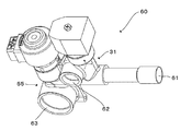
- FIG. 6 is a perspective view showing an external configuration of a valve device 60 in which the fourth flow control device 55 provided in the air conditioning apparatus 100 and the electromagnetic valve 31 are combined.
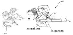
- FIG. 7 is an explanatory diagram for explaining the internal configuration of the valve device 60.
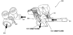
- FIG. 8 is an explanatory diagram for explaining the flow of the refrigerant in the valve device 60 during the heating operation.
- FIG. 9 is an explanatory diagram for explaining the flow of the refrigerant in the valve device 60 during the cooling operation.
- the valve device 60 will be described with reference to FIGS. 7 to 9, a perspective view and a longitudinal sectional view of the main part are shown together.
- the valve device 60 is provided in the air conditioner 100 and is configured by combining the fourth flow rate control device 55 and the electromagnetic valve 31. Therefore, the valve device 60 has a function of opening and closing the flow path and also has a flow rate control function.
- the valve device 60 has a first connection port 61, a second connection port 62, and a third connection port 63.
- the first connection port 61 is configured as a connection port shared by each of the fourth flow control device 55 and the electromagnetic valve 31, and is connected to the first connection pipes 6b, 6c, and 6d.
- the second connection port 62 is configured as a connection port of the electromagnetic valve 31 and is connected to the gas-liquid separator 12.
- the third connection port 63 is configured as a connection port of the fourth flow rate control device 55, and is connected to the first connection pipe 6.
- the valve device 60 shown in FIGS. 6 to 9 has a number corresponding to the number of indoor units to be connected, and the second connection port 62 and the third connection port 63 are linearly connected to form a valve block. To do. And it arrange
- valve device 60 shares the first connection port 61 with the fourth flow control device 55 and the electromagnetic valve 31, thereby increasing the height when the fourth flow control device 55 and the electromagnetic valve 31 are combined. Suppressed. Therefore, even if the valve device 60 is made into a valve block, the height is suppressed, so that the valve device 60 becomes more compact.
- the fourth flow control device 55 is closed and the solenoid valve 31 is controlled to open, so that the refrigerant flows as shown by the arrows in FIG.
- the fourth flow control device 55 is opened stepwise and the solenoid valve 31 is controlled to close, so that the refrigerant flows as shown by the arrows in FIG. Therefore, according to the air conditioner 100, compared with the air conditioner as shown in FIG. 11, compared with what flows a refrigerant
- FIG. 10 is a schematic diagram illustrating an external configuration of a relay machine E applied to the air conditioner 100. Based on FIG. 10, the arrangement
- FIG. 10A shows a plan view of the repeater E
- FIG. 10B shows a side view of the repeater E.
- a valve block in which the valve device 60 shown in FIGS. 6 to 9 is combined is disposed on the front side of the relay E as shown in FIG.
- a first heat exchange unit 19 is disposed on the back side of the relay machine E. And between the 1st heat exchange part 19, the 1st branch part 10, and the 2nd branch part 11, the 2nd heat exchange part 16 is arrange
- the second branch portion 11 is connected to a pipe through which the liquid phase portion of the gas-liquid separator 12 flows, and is internally branched into three pipes, and the first check valves 50b to 50d are connected to the respective pipes. It is configured as follows.
- the second branch portion 11 is connected to the second bypass pipe 51, and is internally branched into three pipes to which the second check valves 52b to 52d are respectively connected.
- the second branch portion 11 is connected to the first connection pipes 7c to 7d, and is connected to the internal first check valves 50b to 50d, respectively.
- the first connecting pipes 7c to 7d are connected to the second branch portion 11, and are connected to the internal second check valves 52b to 52d, respectively.
- first check valve 50 first check valves 50b, 50c, 50d
- second check valve 52 second check valves 52b, 52c, 52d
- the relay machine E is often installed in places where the installation space is limited, such as behind the ceiling. Therefore, during maintenance, the operator often puts his / her body in an inspection port communicating with the installation space and performs unit maintenance of the relay machine E. However, since the occupation ratio of the pipes connected to the indoor units B to D is high on the front side of the repeater E, it is preferable to perform maintenance from the back side of the repeater E. In addition, when mounting a control apparatus in the relay machine E, it is common to also install the control box which accommodates the control apparatus in the back side of the relay machine E. FIG. In consideration of maintenance inside the control box, it is preferable that the maintenance can be executed only from the back side (one direction) of the relay E.
- the conventional air conditioner as shown in FIG. 11 includes a valve block in which the first electromagnetic valve a, the second electromagnetic valve b, and the third electromagnetic valve c are combined.
- the first solenoid valve a, the second solenoid valve b are arranged on the back side of the relay machine, and the third solenoid valve c is arranged on the front side.
- the conventional air conditioner as shown in FIG. 11 in order to realize a compact repeater, a space is secured by adopting a structure in which the first connection pipe is protruded once to the ceiling side, and the height is increased. I try to suppress it. Then, it can be seen that it is difficult to perform all maintenance from the back side of the repeater in the conventional repeater of the air conditioner as shown in FIG.
- the operator performs maintenance of the relay machine E from the back side of the relay machine E.
- Maintenance parts that is, actuator parts such as valves constituting the first branch part 10 and the second branch part 11 are arranged on the front side of the relay unit E.
- the valve device 60 constituting the first branch block 10 includes the fourth flow rate control device 55 and the electromagnetic valve 31 combined so as to be aligned in the extending direction of the first connection port 61. Since the connection port 61 is arranged so as to face the back side (heat exchanger side) of the relay machine E, even if the first branch portion 10 is arranged on the front side of the relay machine E, Maintenance from the back side is possible.
- the piping configuration is complicated by blocking the valves (check valves, solenoid valves, and flow rate control devices) that constitute a part of the first branch portion 10 and the second branch portion 11. Can be avoided.
- the height can be suppressed by configuring the valve device 60, a compact design is possible while avoiding complication of the piping configuration.
- the maintenance parts are arranged on the front side of the relay machine E, the maintenance work can be facilitated.
- the air conditioner 100 has a configuration in which all maintenance parts can be easily accessed from the back side of the repeater E. Further, in the air conditioner 100, the first branch portion 10 is disposed above the second branch portion 11. By doing in this way, in the air conditioning apparatus 100, the compact unit structure is implement
- the first branch part 10 is disposed above the second branch part 11, so that a coil (an electromagnetic valve of the fourth flow control device 55) that is a maintenance component of the valve device 60 is provided.
- the coil portion, the solenoid valve coil portion of the solenoid valve 31) can be disposed near the portion where the operator performs maintenance. Therefore, according to the air conditioning apparatus 100, the maintainability of the solenoid valve coil portion of the valve device 60 configured by combining the fourth flow control device 55 and the solenoid valve 31 is also improved.
- the relay device E includes the valve block of the valve device 60 in which the fourth flow control device 55 and the electromagnetic valve 31 are combined, so that the piping configuration is not complicated. While achieving compactness. This is particularly effective when the repeater E is installed in a place where the height is limited. Moreover, according to the air conditioning apparatus 100, since it is the structure which can access easily all the maintenance components from the back side of the relay machine E, the simplification of a maintenance work is implement
- the opening degree of the fourth flow control device 55 can be maintained in an appropriate state based on the information from the third pressure detection means 56, so when switching from the heating operation to the cooling operation.
- the refrigerant flow noise generated in the first and second refrigerant valves can be significantly reduced as compared with a configuration in which the first branch portion is constituted by a plurality of solenoid valves.
Landscapes
- Engineering & Computer Science (AREA)
- Physics & Mathematics (AREA)
- Mechanical Engineering (AREA)
- Thermal Sciences (AREA)
- General Engineering & Computer Science (AREA)
- Compression-Type Refrigeration Machines With Reversible Cycles (AREA)
Abstract
熱源機から中継器を介して複数台の室内機に冷媒を供給して冷房及び/又は暖房運転する空気調和装置であって、中継器に、複数台の室内機のそれぞれの室内側熱交換器の冷媒出入口の一方を第1の接続配管(6)または第2の接続配管(7)に切り換え接続する第1の分岐部(10)が設置され、第1の分岐部(10)に、第1の接続配管(6)側から複数に分岐してそれぞれの室内側熱交換器(5)に接続された配管のそれぞれに設けられた分岐側流量制御装置(55)と、それぞれの分岐側流量制御装置(55)とそれぞれの室内側熱交換器(5)とを接続している配管から分岐されたそれぞれの配管に設けられた電磁弁(31)と、が設けられている。
Description
本発明は、熱源機により作られた温熱、冷熱、又は温熱と冷熱の両方を複数の負荷に対して効率よく供給することを可能にした冷媒回路及び構造を備えた例えばビル用マルチエアコン等に用いられる空気調和装置に関するものである。
従来から、ビル用マルチエアコンなどの空気調和装置においては、たとえば室外に配置した熱源機である室外機と室内に配置した室内機との間に冷媒を循環させることによって冷房運転又は暖房運転を実行するようになっている。具体的には、冷媒が吸熱して冷却された空気あるいは冷媒が放熱して加熱された空気により空調対象空間の冷房または暖房を行なっていた。このような空気調和装置に使用される冷媒としては、たとえばHFC(ハイドロフルオロカーボン)系冷媒が多く使われている。また、二酸化炭素(CO2 )等の自然冷媒を使うものも提案されている。
そのようなものとして、熱源機と複数台の室内機とを接続し、熱源機から複数台の室内機に冷媒を供給して冷暖房運転を可能とした空気調和装置が存在している(たとえば、特許文献1参照)。特許文献1に記載の空気調和装置においては、第1の接続配管(6b、6c、6d)と、第1の接続配管(6)または第2の接続配管(7)に切換可能に接続する三方切換弁(8)よりなる第1の分岐部(10)と、室内機側の第2の接続配管(7b、7c、7d)と第2の接続配管(7)とを逆止弁(50b、50c、50d、52b、52c、52d)を介して接続する第2の分岐部(11)と、を備えている。
特許文献1に記載の空気調和装置では、暖房運転しようとする室内機に流入させる冷媒と冷房運転している室内機から流入してくる冷媒の切換えを第1の分岐部(10)の三方切換弁(8)で行っている。そのため、室内機が冷房運転をする場合は、三方切換弁(8)の接続口のうちの一つ(第1口8a)は閉路、接続口のうちの二つ(第2口8bおよび第3口8c)は開路となる。また、室内機が暖房運転をする場合は、接続口のうちの一つ(第2口8b)は閉路、接続口のうちの二つ(第1口8aおよび第3口8c)は開路となる。
そして、室内機が冷房運転をする場合、冷媒は第1の接続配管(6)が低圧、第2の接続配管(7)が高圧となるため、三方切換弁(8)の接続口のうちの一つの接続口(第1口8a)側の接続配管では高圧、もう一つの接続口(第2口8b)側の接続配管では低圧、更にもう一つの接続口(第3口8c)側の接続配管では低圧の状態になる。また、冷房運転時においては、冷媒は室内側熱交換器(5)の出口スーパーヒート量により制御されており、室内機側の第1の接続配管(6b、6c、6d)では低圧ガス状態の冷媒が流れている。
また、室内機が暖房運転をする場合、冷媒は第1の接続配管(6)が低圧、第2の接続配管(7)が高圧となるため、三方切換弁(8)の接続口のうちの一つの接続口(第1口8a)側の接続配管では高圧、もう一つの接続口(第2口8b)側の接続配管では低圧、更にもう一つの接続口(第3口8c)側の接続配管では高圧の状態になる。また、暖房運転時においては、冷媒は室内側熱交換器(5)の出口サブクール量により制御されており、室内機側の第1の接続配管(6b、6c、6d)では高温高圧ガス状態の冷媒が流れており、室内側熱交換器(5)および室内側熱交換器(5)から第1の流量制御装置(9)までの接続配管には高温高圧液状態の冷媒が存在する。
よって、接続される室内機の運転を暖房運転から冷房運転に切換える際には、暖房時に流れていた高温高圧ガス冷媒と高温高圧液冷媒が、三方切換弁(8)を通過して低圧の状態にある第1の接続配管(6)に流入することになる。接続される室内機の運転を暖房運転から冷房運転に切換時、三方切換弁(8)では、三方切換弁(8)を通過する冷媒の高圧と低圧とのバランスによって冷媒流動音を発生する。特に、高温高圧液冷媒の流動音が大きくなる。
そのため、三方切換弁(8)に代えて電磁弁(電磁開閉弁)を用いるようにした空気調和装置が存在している(たとえば、特許文献2参照)。特許文献2に記載の空気調和装置においては、第2の電磁弁(8b)を暖房用に、第1の電磁弁(8a)、オリフィス機能付きの第3の電磁弁(8c)を冷房用に使用して、冷房運転への切換えの際には高温高圧液冷媒の流動音を軽減するため第1、第3の電磁弁に段階的に冷媒を流していた。また、特許文献2に記載の空気調和装置では、流量制御装置の開口径を小さくしたり、流量制御装置をパルス制御したり、第3の電磁弁の開口径を小さくしたりすることにより冷媒流動音を低減していた。
また、三方切換弁(8)に代えて電磁弁(電磁開閉弁)を用い、コンパクト化を図るようにした他の空気調和装置も存在している(図11参照)。この空気調和装置においては、第2の電磁弁bを暖房用に、第1の電磁弁a、第3の電磁弁c、オリフィスdを冷房用に使用している。つまり、図11に示す空気調和装置では、冷房運転への切換えの際には高温高圧液冷媒の流動音を軽減するため、オリフィスd、第3の電磁弁c、第1の電磁弁aに段階的に冷媒を流すようにしていた。なお、図11では、本発明の実施の形態に係る空気調和装置に相当するものには同符号を付記している。
特許文献2や図11に記載の空気調和装置によれば、冷媒流動音を軽減することができるものの、1台の室内機に対して電磁弁を2台又は3台必要とするため、分岐部には室内機の台数×2台又は3台の電磁弁を備えなければならない。そのために、コンパクト化を考慮して電磁弁をブロック化したとしても、特に高さ方向の低減には限界が生じてしまう。また、電磁弁をブロック化したとしても、配管構成が複雑になることにより、ある一つの方向からのメンテナンス作業が困難でもあった。
本発明は、上記のような課題を解決するためになされたもので、静音性を維持しながら、コンパクトかつメンテナンス性の向上を図ることができる空気調和装置を提供することを目的とする。
本発明に係る空気調和装置は、圧縮機、切換弁および熱源機側熱交換器を有する熱源機と、それぞれ室内側熱交換器および室内側流量制御装置を有する複数台の室内機と、を第1の接続配管および第2の接続配管を介して接続し、前記熱源機から前記複数台の室内機に冷媒を供給して冷暖房運転する空気調和装置であって、前記複数台の室内機のそれぞれの前記室内側熱交換器の一方を前記第1の接続配管または前記第2の接続配管に切り換え接続する第1の分岐部と、一側が前記第2の接続配管に接続され、他側が複数に分岐して前記複数台の室内機のそれぞれの前記室内側熱交換器の他方に前記室内側流量制御装置を介して接続された第2の分岐部と、が設置される中継機を備え、前記第1の分岐部には、前記第1の接続配管側から複数に分岐してそれぞれの前記室内側熱交換器に接続された配管のそれぞれに設けられた分岐側流量制御装置と、それぞれの前記分岐側流量制御装置とそれぞれの前記室内側熱交換器とを接続している配管から分岐されたそれぞれの配管に設けられた電磁弁と、が設けられているものである。
本発明に係る空気調和装置によれば、分岐流量制御装置及び電磁弁を組み合わせた弁装置を備えたので、コンパクトかつメンテナンス性を向上することができる。
以下、本発明の実施の形態を図面に基づいて説明する。なお、図1を含め、以下の図面では各構成部材の大きさの関係が実際のものとは異なる場合がある。また、図1を含め、以下の図面において、同一の符号を付したものは、同一又はこれに相当するものであり、このことは明細書の全文において共通することとする。さらに、明細書全文に表わされている構成要素の形態は、あくまでも例示であって、これらの記載に限定されるものではない。
図1は、本発明の実施の形態に係る空気調和装置100の冷媒系を中心とする全体構成図である。また、図2~図5は、空気調和装置100の冷暖房運転時の動作状態を示したものである。図2は冷房運転のみの運転動作状態図、図3は暖房運転のみの運転動作状態図を、図4は冷暖房同時運転の冷房運転容量が暖房運転容量より大きい冷房主体運転の運転動作状態図を、図5は冷暖房同時運転の暖房運転容量が冷房運転容量より大きい暖房主体運転の運転動作状態図を、それぞれ示している。なお、この実施の形態では、熱源機1台に室内機3台を接続した場合について説明するが、2台以上の室内機を接続した場合も同様である。
図1に示すように、空気調和装置100は、熱源機A、室内機B、C、D(以下、何の断りもしないときは単に室内機として表記する)、中継機Eが接続されて構成されている。熱源機Aは、室内機に温熱又は冷熱を供給する機能を有している。室内機は、後述するように互いに並列接続されており、それぞれ同じ構成となっている。室内機は、熱源機Aから供給される温熱又は冷熱により室内等の空調対象空間の空調を実行する機能を有している。中継機Eは、熱源機Aと室内機との間に介在し、室内機からの要求に応じて熱源機Aから供給される冷媒の流れを切り換える機能を有している。
熱源機Aは、容量可変な圧縮機1、熱源機Aでの冷媒流通方向を切換える四方切換弁2、蒸発器又は凝縮器(放熱器)として機能する熱源機側熱交換器3、四方切換弁2を介して圧縮機1の吸入側に接続されているアキュムレータ4、熱源機側熱交換器3に空気を送風する送風量可変の熱源機側送風機20、冷媒流通方向を制限する熱源機側切換弁40を、備えている。そして、これらによって熱源機Aは構成される。なお、四方切換弁2が本発明の「切換弁」に相当する。ただし、「切換弁」を四方切換弁ではなく、二方弁、三方弁等を組み合わせて「切換弁」を構成してもよい。
室内機は、凝縮器(放熱器)又は蒸発器として機能する室内側熱交換器5、冷房時は室内側熱交換器5の出口側のスーパーヒート量により、暖房時は室内側熱交換器5の出口側のサブクール量により制御される第1の流量制御装置(室内側流量制御装置)9を備えている。そして、これらによって室内機は構成される。
中継機Eは、第1の分岐部10、第2の流量制御装置13、第2の分岐部11、気液分離装置12、熱交換部(第1の熱交換部19、第2の熱交換部16)、第3の流量制御装置15が内蔵されている。そして、これらによって中継機Eは構成される。
熱源機Aの四方切換弁2と中継機Eとは、太い第1の接続配管6で接続されている。
室内機の室内側熱交換器5と中継機Eとは、第1の接続配管6に対応する室内機側の第1の接続配管6b、6c、6dのそれぞれで接続されている。
熱源機Aの熱源機側熱交換器3と中継機Eとは、第1の接続配管6より細い第2の接続配管7で接続されている。
室内機の室内側熱交換器5と中継機Eとは、第1の接続配管6を介して接続するとともに、第2の接続配管7に対応する室内機側の第2の接続配管7b、7c、7dのそれぞれで接続されている。
室内機の室内側熱交換器5と中継機Eとは、第1の接続配管6に対応する室内機側の第1の接続配管6b、6c、6dのそれぞれで接続されている。
熱源機Aの熱源機側熱交換器3と中継機Eとは、第1の接続配管6より細い第2の接続配管7で接続されている。
室内機の室内側熱交換器5と中継機Eとは、第1の接続配管6を介して接続するとともに、第2の接続配管7に対応する室内機側の第2の接続配管7b、7c、7dのそれぞれで接続されている。
第1の分岐部10は、室内機側の第1の接続配管6b、6c、6dと、第1の接続配管6または第2の接続配管7側とを、切換可能に接続する機能を有する。
第1の分岐部10には、室内機側の第1の接続配管6b、6c、6dと、第1の接続配管6と、に接続されている第4の流量制御装置(分岐側流量制御装置)55、及び、室内機側の第1の接続配管6b、6c、6dと、第1の接続配管6側と、に接続されている弁装置としての電磁弁31が搭載されている。
第1の分岐部10には、室内機側の第1の接続配管6b、6c、6dと、第1の接続配管6と、に接続されている第4の流量制御装置(分岐側流量制御装置)55、及び、室内機側の第1の接続配管6b、6c、6dと、第1の接続配管6側と、に接続されている弁装置としての電磁弁31が搭載されている。
第2の分岐部11は、室内機側の第2の接続配管7b、7c、7dと、第2の接続配管7と、の接続を冷媒の流れに応じて切り換える機能を有する。
第2の分岐部11には、後述する第1の逆止弁50(第1の逆止弁50b、50c、50d)、及び、後述する第2の逆止弁52(第2の逆止弁52b、52c、52d)が搭載されている。
第2の分岐部11には、後述する第1の逆止弁50(第1の逆止弁50b、50c、50d)、及び、後述する第2の逆止弁52(第2の逆止弁52b、52c、52d)が搭載されている。
気液分離装置12は、第2の接続配管7の途中に設けられ、その気相部は第1の分岐部10の電磁弁31に接続され、その液相部は第2の分岐部11に接続されている。
第2の流量制御装置13は、第2の接続配管7の気液分離装置12と第2の分岐部11との間に設けられており、たとえば開閉自在な電気式膨張弁等で構成されている。
なお、第2の分岐部11と第1の接続配管6とは、第1のバイパス配管14で接続されている。
第2の流量制御装置13は、第2の接続配管7の気液分離装置12と第2の分岐部11との間に設けられており、たとえば開閉自在な電気式膨張弁等で構成されている。
なお、第2の分岐部11と第1の接続配管6とは、第1のバイパス配管14で接続されている。
第3の流量制御装置15は、第1のバイパス配管14の途中に設けられており、たとえば開閉自在な電気式膨張弁等で構成されている。
第2の熱交換部16は、第1のバイパス配管14の第3の流量制御装置15の下流に設けられ、第2の接続配管7の第2の流量制御装置13より下流の部分との間でそれぞれ熱交換を行うようになっている。
第1の熱交換部19は、第1のバイパス配管14の第2の熱交換部16の下流に設けられ、第2の接続配管7の第2の流量制御装置13より上流の部分との間でそれぞれ熱交換を行うようになっている。
第2の熱交換部16は、第1のバイパス配管14の第3の流量制御装置15の下流に設けられ、第2の接続配管7の第2の流量制御装置13より下流の部分との間でそれぞれ熱交換を行うようになっている。
第1の熱交換部19は、第1のバイパス配管14の第2の熱交換部16の下流に設けられ、第2の接続配管7の第2の流量制御装置13より上流の部分との間でそれぞれ熱交換を行うようになっている。
第1の逆止弁50b、50c、50dは、それぞれ第2の分岐部11の室内機側の第2の接続配管7b、7c、7dの途中に設けられており、第2の接続配管7から室内機側の第2の接続配管7b、7c、7dへのみ冷媒流通を許容する。
なお、室内機側の第2の接続配管7b、7c、7dの第1の逆止弁50b、50c、50dの下流部と第2の接続配管7の第2の流量制御装置13の下流、かつ、第2の熱交換部16の上流の配管部とは、第2のバイパス配管51で接続されている。そして、第2のバイパス配管51中の室内機側の第2の接続配管7b、7c、7dに接続する配管と第2のバイパス配管51中の第2の接続配管7に接続する配管が途中で合流する。
なお、室内機側の第2の接続配管7b、7c、7dの第1の逆止弁50b、50c、50dの下流部と第2の接続配管7の第2の流量制御装置13の下流、かつ、第2の熱交換部16の上流の配管部とは、第2のバイパス配管51で接続されている。そして、第2のバイパス配管51中の室内機側の第2の接続配管7b、7c、7dに接続する配管と第2のバイパス配管51中の第2の接続配管7に接続する配管が途中で合流する。
第2の逆止弁52b、52c、52dは、第2のバイパス配管51の途中の室内機側の第2の接続配管7b、7c、7dに接続する配管が第2のバイパス配管51中の第2の接続配管7に接続する配管と合流する部分より上流部に設けられており、室内機側の第2の接続配管7b、7c、7dから第2の接続配管7へのみ冷媒流通を許容する。
なお、第2の接続配管7から第1の逆止弁50b、50c、50dが設けられた室内機側の第2の接続配管7b、7c、7dを介して第1の流量制御装置9に至る流路が第1の冷媒流路を構成し、第1の流量制御装置9から室内機側の第2の接続配管7b、7c、7dおよび第2の逆止弁52b、52c、52dが設けられた第2のバイパス配管51を介して第2の接続配管7に至る流路が第2の冷媒流路を構成している。
なお、第2の接続配管7から第1の逆止弁50b、50c、50dが設けられた室内機側の第2の接続配管7b、7c、7dを介して第1の流量制御装置9に至る流路が第1の冷媒流路を構成し、第1の流量制御装置9から室内機側の第2の接続配管7b、7c、7dおよび第2の逆止弁52b、52c、52dが設けられた第2のバイパス配管51を介して第2の接続配管7に至る流路が第2の冷媒流路を構成している。
第3の逆止弁32は、熱源機側熱交換器3と第2の接続配管7とを連結する配管の途中に設けられ、熱源機側熱交換器3から第2の接続配管7へのみ冷媒流通を許容する。
第4の逆止弁33は、熱源機Aの四方切換弁2と第1の接続配管6とを連結する配管の途中に設けられ、第1の接続配管6から四方切換弁2へのみ冷媒流通を許容する。
第5の逆止弁34は、熱源機Aの四方切換弁2と第2の接続配管7とを連結する配管の途中に設けられ、四方切換弁2から第2の接続配管7へのみ冷媒流通を許容する。
第6の逆止弁35は、熱源機側熱交換器3と第1の接続配管6とを連結する配管の途中に設けられ、第1の接続配管6から熱源機側熱交換器3へのみ冷媒流通を許容する。
第3の逆止弁32、第4の逆止弁33、第5の逆止弁34、第6の逆止弁35で熱源機側切換弁40を構成している。
第4の逆止弁33は、熱源機Aの四方切換弁2と第1の接続配管6とを連結する配管の途中に設けられ、第1の接続配管6から四方切換弁2へのみ冷媒流通を許容する。
第5の逆止弁34は、熱源機Aの四方切換弁2と第2の接続配管7とを連結する配管の途中に設けられ、四方切換弁2から第2の接続配管7へのみ冷媒流通を許容する。
第6の逆止弁35は、熱源機側熱交換器3と第1の接続配管6とを連結する配管の途中に設けられ、第1の接続配管6から熱源機側熱交換器3へのみ冷媒流通を許容する。
第3の逆止弁32、第4の逆止弁33、第5の逆止弁34、第6の逆止弁35で熱源機側切換弁40を構成している。
中継機Eには、第1の圧力検出手段25、第2の圧力検出手段26、及び、第3の圧力検出手段56が設けられている。
第1の圧力検出手段25は、第2の接続配管7の第1の分岐部10と第2の流量制御装置13との間に設けられている。
第2の圧力検出手段26は、第2の流量制御装置13と第1の流量制御装置9との間に設けられている。
第3の圧力検出手段56は、第1の接続配管6と第1のバイパス配管14との接続位置に設けられている。
第1の圧力検出手段25は、第2の接続配管7の第1の分岐部10と第2の流量制御装置13との間に設けられている。
第2の圧力検出手段26は、第2の流量制御装置13と第1の流量制御装置9との間に設けられている。
第3の圧力検出手段56は、第1の接続配管6と第1のバイパス配管14との接続位置に設けられている。
室内機には、第1の温度検出手段53及び第2の温度検出手段54が設けられている。
第1の温度検出手段53は、室内機の第1の分岐部10側に設けられている。
第2の温度検出手段54は、室内機の第2の分岐部11側に設けられている。
つまり、第1の温度検出手段53及び第2の温度検出手段54は、室内側熱交換器5の両端に設けられ、第1の流量制御装置9側に接続されるものが第2の温度検出手段54、他端に接続されるものが第1の温度検出手段53である。
第1の温度検出手段53は、室内機の第1の分岐部10側に設けられている。
第2の温度検出手段54は、室内機の第2の分岐部11側に設けられている。
つまり、第1の温度検出手段53及び第2の温度検出手段54は、室内側熱交換器5の両端に設けられ、第1の流量制御装置9側に接続されるものが第2の温度検出手段54、他端に接続されるものが第1の温度検出手段53である。
また、熱源機側熱交換器3は、第1の熱源機側熱交換器41および第2の熱源機側熱交換器42、熱源機側バイパス路43、第1の電磁開閉弁44、第2の電磁開閉弁45、第3の電磁開閉弁46、第4の電磁開閉弁47、第5の電磁開閉弁48によって構成されている。なお、熱源機側熱交換器3には、熱源機側熱交換器3の熱交換容量を制御する熱源機側送風機20が設けられている。
第1の熱源機側熱交換器41および第2の熱源機側熱交換器42は、同じ伝熱面積を有し互いに並列に接続されている。
熱源機側バイパス路43は、第1の熱源機側熱交換器41および第2の熱源機側熱交換器42に並列に接続されている。
第1の電磁開閉弁44は、第1の熱源機側熱交換器41の四方切換弁2と接続する側の一端に設けられている。
第2の電磁開閉弁45は、第1の熱源機側熱交換器41の他端に設けられている。
第3の電磁開閉弁46は、第2の熱源機側熱交換器42の四方切換弁2と接続する側の一端に設けられている。
第4の電磁開閉弁47は、第2の熱源機側熱交換器42の他端に設けられている。
第5の電磁開閉弁48は、熱源機側バイパス路43の途中に設けられている。
熱源機側バイパス路43は、第1の熱源機側熱交換器41および第2の熱源機側熱交換器42に並列に接続されている。
第1の電磁開閉弁44は、第1の熱源機側熱交換器41の四方切換弁2と接続する側の一端に設けられている。
第2の電磁開閉弁45は、第1の熱源機側熱交換器41の他端に設けられている。
第3の電磁開閉弁46は、第2の熱源機側熱交換器42の四方切換弁2と接続する側の一端に設けられている。
第4の電磁開閉弁47は、第2の熱源機側熱交換器42の他端に設けられている。
第5の電磁開閉弁48は、熱源機側バイパス路43の途中に設けられている。
また、熱源機Aには、第4の圧力検出手段18が設けられている。第4の圧力検出手段18は、四方切換弁2と圧縮機1の吐出部とを接続する配管途中に設けられている。
空気調和装置100は、制御装置70を有している。この制御装置70は、空気調和装置100のシステム全体を統括制御するものである。具体的には、制御装置70は、圧縮機1の駆動周波数、熱源機側送風機20及び室内側熱交換器5に設けられている送風機の回転数、四方切換弁2の切り替え、各電磁弁の開閉、各絞り装置の開度等を制御する。つまり、制御装置70は、上述した温度検出手段及び圧力検出手段からの検出情報及びリモコン(図示省略)からの指示に基づいて、各アクチュエーター(圧縮機1、四方切換弁2、各電磁弁(第1の電磁開閉弁44~第5の電磁開閉弁48、電磁弁31)、各絞り装置(第1の流量制御装置9、第2の流量制御装置13、第3の流量制御装置15、第4の流量制御装置55)等の駆動部品)を制御する。
なお、空気調和装置100内に充填される冷媒の種類を特に限定するものではなく、たとえば二酸化炭素(CO2 )や炭化水素、ヘリウムなどの自然冷媒、HFC410AやHFC407C(HFCのR32/R125/R134aが23/25/52wt%の比率で混合されている非共沸混合冷媒)、HFC404Aなどの塩素を含まない代替冷媒、若しくは既存の製品に使用されているR22やR134aなどのフロン系冷媒のいずれを使用してもよい。
熱源機側熱交換器3及び室内側熱交換器5が、冷媒と空気との間で熱交換を行うものである場合を例に説明したが、冷媒と空気以外の熱媒体、たとえば水やブライン等と熱交換を行うものであってもよい。
熱源機側熱交換器3及び室内側熱交換器5が、冷媒と空気との間で熱交換を行うものである場合を例に説明したが、冷媒と空気以外の熱媒体、たとえば水やブライン等と熱交換を行うものであってもよい。
また、本実施の形態では、空気調和装置100に熱源機Aが1台搭載されている場合を例に示しているが、これに限定するものではなく、2台以上の熱源機Aが搭載されていてもよい。さらに、室内機が3台搭載されている場合を例に示しているが、これに限定するものではなく、4台以上が搭載されていてもよい。制御装置70は、熱源機A、室内機、中継機Eのいずれかに搭載してもよいし、それらの全部に搭載してもよい。また、熱源機A、室内機、中継機Eとは別に制御装置70を搭載してもよい。そして、複数で制御装置70を構成する場合は、互いに無線又は有線で通信可能に接続するとよい。
次に、空気調和装置100の動作について説明する。
[冷房運転]
まず、図2を参照しつつ冷房運転のみの運転状態について説明する。図2では、室内機B、C、Dの全部で冷房運転を行っている状態を例に示している。
[冷房運転]
まず、図2を参照しつつ冷房運転のみの運転状態について説明する。図2では、室内機B、C、Dの全部で冷房運転を行っている状態を例に示している。
圧縮機1より吐出された高温高圧冷媒ガスは、図2に示すように、四方切換弁2を通り、熱源機側熱交換器3で送風量可変の熱源機側送風機20によって送風される空気と熱交換して凝縮液化される。この冷媒は、その後、第3の逆止弁32、第2の接続配管7、気液分離装置12、第2の流量制御装置13の順に通り、更に第2の分岐部11、室内機側の第2の接続配管7b、7c、7dを通り、各室内機B、C、Dに流入する。
そして、室内機B、C、Dに流入した冷媒は、各室内側熱交換器5の出口のスーパーヒート量により制御される第1の流量制御装置9により低圧まで減圧される。減圧された冷媒は、室内側熱交換器5に流入し、室内側熱交換器5で室内空気と熱交換して蒸発しガス化され室内を冷房する。そして、このガス状態となった冷媒は、室内機側の第1の接続配管6b、6c、6d、第1の分岐部10の第4の流量制御装置55、第1の接続配管6、第4の逆止弁33、熱源機の四方切換弁2、アキュムレータ4を経て圧縮機1に吸入される。このようにして循環サイクルを構成し、冷房運転を行う。
この時、各電磁弁31は、閉制御されている。そして、第1の接続配管6が低圧、第2の接続配管7が高圧のため、冷媒は必然的に第3の逆止弁32、第4の逆止弁33へ流通する。
また、第4の流量制御装置55は、第3の圧力検出手段56からの検知情報によって得られる冷媒の状態に基づいて開度が制御されている。
また、第4の流量制御装置55は、第3の圧力検出手段56からの検知情報によって得られる冷媒の状態に基づいて開度が制御されている。
また、この循環サイクルにおいて、第2の流量制御装置13を通過した冷媒の一部が第1のバイパス配管14へ入る。そして、第3の流量制御装置15で低圧まで減圧された後、第2の熱交換部16において第2の流量制御装置13を通過した冷媒(第1のバイパス配管14に分岐する前の冷媒)との間で熱交換を行って蒸発する。更に、第1の熱交換部19において第2の流量制御装置13に流入する前の冷媒との間で熱交換を行って蒸発する。この蒸発した冷媒は、第1の接続配管6、第4の逆止弁33へ入り熱源機の四方切換弁2、アキュムレータ4を経て圧縮機1に吸入される。
一方、第1の熱交換部19および第2の熱交換部16において第1のバイパス配管14へ入って第3の流量制御装置15で低圧まで減圧された冷媒との間で熱交換を行って冷却され、サブクールを充分につけられた冷媒は、第2の分岐部11の第1の逆止弁50b、50c、50dを通って、冷房しようとしている室内機B、C、Dへ流入する。ここで、室内機の蒸発温度および熱源機側熱交換器3の凝縮温度が予め定められた目標温度になるように容量可変な圧縮機1の容量および熱源機側送風機20の送風量を調節し、各室内機では目標とする冷房能力を得ることができる。なお、熱源機側熱交換器3の凝縮温度は、第4の圧力検出手段18で検出される圧力の飽和温度として求められる。
[暖房運転]
次いで、図3を参照しつつ暖房運転のみの運転状態について説明する。図3では、室内機B、C、Dの全部で暖房運転を行っている状態を例に示している。
次いで、図3を参照しつつ暖房運転のみの運転状態について説明する。図3では、室内機B、C、Dの全部で暖房運転を行っている状態を例に示している。
圧縮機1より吐出された高温高圧冷媒ガスは、図3に示すように、四方切換弁2を通り、第5の逆止弁34、第2の接続配管7、気液分離装置12、第1の分岐部10の電磁弁31、室内機側の第1の接続配管6b、6c、6dの順に通り、室内機B、C、Dに流入する。室内機B、C、Dに流入した冷媒は、室内空気と熱交換して凝縮液化し、室内を暖房する。そして、この状態となった冷媒は、各室内側熱交換器5の出口サブクール量により制御されて第1の流量制御装置9を通る。
第1の流量制御装置9を通った冷媒は、室内機側の第2の接続配管7b、7c、7dから第2の分岐部11に流入し、第2の逆止弁52b、52c、52dを通った後合流する。第2の分岐部11で合流した冷媒は、更に第2の接続配管7途中の第2の流量制御装置13と第2の熱交換部16との間に導かれ、第3の流量制御装置15を通る。また、ここで冷媒は、第1の流量制御装置9または第3の流量制御装置15で低圧の気液二相まで減圧される。
そして、低圧まで減圧された冷媒は、第1の接続配管6を経て熱源機Aの第6の逆止弁35、熱源機側熱交換器3に流入し、ここで送風量可変の熱源機側送風機20によって送風される空気と熱交換して蒸発する。この蒸発してガス状態となった冷媒は、四方切換弁2、アキュムレータ4を経て圧縮機1に吸入される。このようにして循環サイクルを構成し、暖房運転を行う。
この時、各電磁弁31は、開制御されている。
また、第4の流量制御装置55は、閉止されている。
また、第4の流量制御装置55は、閉止されている。
また、この循環サイクルにおいては、第1の接続配管6が低圧、第2の接続配管7が高圧であるために、冷媒は必然的に第5の逆止弁34、第6の逆止弁35へ流通する。また、第1の逆止弁50b、50c、50dは室内機側の第2の接続配管7b、7c、7dが第2の接続配管7よりも高圧であるために、閉の状態となる。ここで、室内機の凝縮温度および熱源機側熱交換器3の蒸発温度が予め定められた目標温度になるように容量可変な圧縮機1の容量および熱源機側送風機20の送風量を調節し、各室内機では目標とする暖房能力を得ることができる。
[冷房主体運転]
次いで、図4を参照しつつ冷房主体運転の運転状態について説明する。図4では、室内機B、Cから冷房要求があり、室内機Dから暖房要求がある場合の冷房主体運転を例に示している。
次いで、図4を参照しつつ冷房主体運転の運転状態について説明する。図4では、室内機B、Cから冷房要求があり、室内機Dから暖房要求がある場合の冷房主体運転を例に示している。
圧縮機1より吐出された高温高圧冷媒ガスは、図4に示すように、四方切換弁2を経て熱源機側熱交換器3に流入し、ここで送風量可変の熱源機側送風機20によって送風される空気と熱交換して二相の高温高圧状態となる。
ここで、室内機の蒸発温度および凝縮温度が予め定められた目標温度になるように容量可変な圧縮機1の容量および熱源機側送風機20の送風量を調節する。かつ、第1の熱源機側熱交換器41および第2の熱源機側熱交換器42の両端の第1の電磁開閉弁44、第2の電磁開閉弁45、第3の電磁開閉弁46、第4の電磁開閉弁47を開閉して伝熱面積を調整する。かつ、熱源機側バイパス路43の第5の電磁開閉弁48を開閉して第1の熱源機側熱交換器41および第2の熱源機側熱交換器42を流通する冷媒流量を調整する。このようにすることにより、熱源機側熱交換器3で任意量の熱交換量が得られ、また、各室内機では目標とする暖房能力または冷房能力を得ることができる。
その後、この二相の高温高圧状態の冷媒は、第3の逆止弁32、第2の接続配管7を経て、中継機Eの気液分離装置12へ送られ、ガス状態冷媒と液状態冷媒とに分離される。
そして、気液分離装置12で分離されたガス状冷媒が、第1の分岐部10の電磁弁31、室内機側の第1の接続配管6dの順に通り、暖房しようとする室内機Dに流入し、室内側熱交換器5で室内空気と熱交換して凝縮液化し、室内を暖房する。更に、室内側熱交換器5を流出した冷媒は、室内機Dの室内側熱交換器5の出口サブクール量により制御された第1の流量制御装置9を通り、少し減圧されて第2の分岐部11に流入する。この冷媒は、第2の逆止弁52dを含む第2のバイパス配管51を通って、第2の接続配管7の第2の流量制御装置13の下流部に流入する。
そして、気液分離装置12で分離されたガス状冷媒が、第1の分岐部10の電磁弁31、室内機側の第1の接続配管6dの順に通り、暖房しようとする室内機Dに流入し、室内側熱交換器5で室内空気と熱交換して凝縮液化し、室内を暖房する。更に、室内側熱交換器5を流出した冷媒は、室内機Dの室内側熱交換器5の出口サブクール量により制御された第1の流量制御装置9を通り、少し減圧されて第2の分岐部11に流入する。この冷媒は、第2の逆止弁52dを含む第2のバイパス配管51を通って、第2の接続配管7の第2の流量制御装置13の下流部に流入する。
一方、気液分離装置12で分離された液状冷媒は、第1の圧力検出手段25の検出圧力と第2の圧力検出手段26の検出圧力とによって制御される第2の流量制御装置13を通って暖房しようとする室内機Dを通った冷媒と合流する。その後、第2の熱交換部16に流入し、第2の熱交換部16で冷却される。
そして、この第2の熱交換部16で冷却された冷媒の一部は、第1の逆止弁50b、50c、室内機側の第2の接続配管7b、7cを通り冷房しようとする室内機B、Cに入る。室内機B、Cに流入した冷媒は、室内機B、Cの各室内側熱交換器5の出口のスーパーヒート量により制御される第1の流量制御装置9に入り減圧された後に、室内側熱交換器5に入って熱交換して蒸発しガス状態となって室内を冷房する。その後、第4の流量制御装置55を介して第1の接続配管6に流入する。
一方、第2の熱交換部16で冷却された冷媒の残部は、第1の圧力検出手段25の検出圧力と第2の圧力検出手段26の検出圧力の圧力差が所定範囲となるように制御される第3の流量制御装置15を通る。その後、第2の熱交換部16および第1の熱交換部19で熱交換して蒸発した後、太い第1の接続配管6に流入して室内機B、Cを通った冷媒と合流する。第1の接続配管6で合流した冷媒は、熱源機Aの第4の逆止弁33、四方切換弁2、アキュムレータ4を経て圧縮機1に吸入される。このようにして循環サイクルを構成し、冷房主体運転を行う。
この時、室内機B、Cに接続された電磁弁31は閉制御されており、室内機Dに接続された電磁弁31は開制御されている。
また、室内機B、Cに接続された第4の流量制御装置55は開放されており、室内機Dに接続された第4の流量制御装置55は閉止されている。
また、室内機B、Cに接続された第4の流量制御装置55は開放されており、室内機Dに接続された第4の流量制御装置55は閉止されている。
また、第1の接続配管6が低圧、第2の接続配管7が高圧のため、冷媒は必然的に第3の逆止弁32、第4の逆止弁33へ流入する。
さらに、室内機側の第2の接続配管7b、7cは第2の接続配管7よりも圧力が低いため、第2の逆止弁52b、52cは閉となる。
また、室内機側の第2の接続配管7dは第2の接続配管7よりも圧力が高いため、第1の逆止弁50dは閉となる。
この第1の逆止弁50、第2の逆止弁52によって、暖房要求のある室内機Dを通った冷媒が第2の熱交換部16を通らずにサブクールが充分につかない状態で冷房要求のある室内機B、Cへ流れ込むことを防止している。
さらに、室内機側の第2の接続配管7b、7cは第2の接続配管7よりも圧力が低いため、第2の逆止弁52b、52cは閉となる。
また、室内機側の第2の接続配管7dは第2の接続配管7よりも圧力が高いため、第1の逆止弁50dは閉となる。
この第1の逆止弁50、第2の逆止弁52によって、暖房要求のある室内機Dを通った冷媒が第2の熱交換部16を通らずにサブクールが充分につかない状態で冷房要求のある室内機B、Cへ流れ込むことを防止している。
[暖房主体運転]
次いで、図5を参照しつつ暖房主体運転の運転状態について説明する。図5では、室内機B、Cから暖房要求があり、室内機Dから冷房要求がある場合の暖房主体運転を例に示している。
次いで、図5を参照しつつ暖房主体運転の運転状態について説明する。図5では、室内機B、Cから暖房要求があり、室内機Dから冷房要求がある場合の暖房主体運転を例に示している。
圧縮機1より吐出された高温高圧冷媒ガスは、図5に示すように、四方切換弁2、第5の逆止弁34、第2の接続配管7を通って中継機Eへ送られ、気液分離装置12を通る。気液分離装置12を通った冷媒は、第1の分岐部10の電磁弁31、室内機側の第1の接続配管6b、6cの順に通り、暖房しようとする室内機B、Cに流入し、室内側熱交換器5で室内空気と熱交換して凝縮液化され室内を暖房する。この凝縮液化した冷媒は、室内機C、Dの各室内側熱交換器5の出口サブクール量により制御されて第1の流量制御装置9を通り、少し減圧されて第2の分岐部11に流入する。
第2の分岐部11に流入した冷媒は、第2の逆止弁52b、52cを含む第2のバイパス配管を通って第2の接続配管7に合流し、第2の熱交換部16で冷却される。この第2の熱交換部16で冷却された冷媒の一部は、第1の逆止弁50d、室内機側の第2の接続配管7dを通り冷房しようとする室内機Dに入る。そして、室内機Dに入った冷媒は、室内側熱交換器5の出口スーパーヒート量により制御される第1の流量制御装置9に入り減圧された後に、室内側熱交換器5に入って熱交換して蒸発しガス状態となって室内を冷房し、第4の流量制御装置55を介して第1の接続配管6に流入する。
一方、第2の熱交換部16で冷却された冷媒の残部は、第1の圧力検出手段25の検出圧力と第2の圧力検出手段26の検出圧力との圧力差が所定範囲となるように制御される第3の流量制御装置15を通る。第3の流量制御装置15を通った冷媒は、第2の熱交換部16で暖房室内機から出てきた冷媒と熱交換して蒸発する。その後、この冷媒は、冷房しようとする室内機Dを通った冷媒と合流して太い第1の接続配管6を経て熱源機Aの第6の逆止弁35、熱源機側熱交換器3に流入する。熱源機側熱交換器3に流入した冷媒は、ここで送風量可変の熱源機側送風機20によって送風される空気と熱交換して蒸発しガス状態となる。
ここで、冷房要求のある室内機Dの蒸発温度および暖房要求のある室内機B、Cの凝縮温度が予め定められた目標温度になるように容量可変な圧縮機1の容量および熱源機側送風機20の送風量を調節する。かつ、第1の熱源機側熱交換器41および第2の熱源機側熱交換器42の両端の第1の電磁開閉弁44、第2の電磁開閉弁45、第3の電磁開閉弁46、第4の電磁開閉弁47を開閉して伝熱面積を調整する。かつ、熱源機側バイパス路43の第5の電磁開閉弁48を開閉して第1の熱源機側熱交換器41および第2の熱源機側熱交換器42を流通する冷媒流量を調整する。このようにすることにより、熱源機側熱交換器3で任意量の熱交換量が得られ、また、各室内機では目標とする暖房能力または冷房能力を得ることができる。そして、冷媒は、熱源機Aの四方切換弁2、アキュムレータ4を経て圧縮機1に吸入される。このようにして循環サイクルを構成し、暖房主体運転を行う。
この時、室内機B、Cに接続された電磁弁31は開制御されており、室内機Dに接続された電磁弁31は閉制御されている。また、室内機B、Cに接続された第4の流量制御装置55は閉止されており、室内機Dに接続された第4の流量制御装置55は開放されている。
また、冷媒は、第1の接続配管6が低圧、第2の接続配管7が高圧のため、必然的に第5の逆止弁34、第6の逆止弁35へ流通する。この時、第2の流量制御装置13は閉じている。
さらに、室内機側の第2の接続配管7b、7cは第2の接続配管7よりも圧力が高いため、第1の逆止弁50b、50cは閉となる。
また、室内機側の第2の接続配管7dは第2の接続配管7よりも圧力が低いため、第2の逆止弁52dは閉となる。
この第1の逆止弁50、第2の逆止弁52によって、暖房室内機B、Cを通った冷媒が第2の熱交換部16を通らずにサブクールが充分につかない状態で冷房室内機Dへ流れ込むことを防止している。
さらに、室内機側の第2の接続配管7b、7cは第2の接続配管7よりも圧力が高いため、第1の逆止弁50b、50cは閉となる。
また、室内機側の第2の接続配管7dは第2の接続配管7よりも圧力が低いため、第2の逆止弁52dは閉となる。
この第1の逆止弁50、第2の逆止弁52によって、暖房室内機B、Cを通った冷媒が第2の熱交換部16を通らずにサブクールが充分につかない状態で冷房室内機Dへ流れ込むことを防止している。
[第4の流量制御装置55の開度制御]
第4の流量制御装置55は、第3の圧力検出手段56からの検知情報によって得られる冷媒の状態に基づいて開度が制御される。つまり、制御装置70は、第3の圧力検出手段56が検知した圧力情報から第4の流量制御装置55に流入する冷媒の状態を判断し、その判断結果に基づいて第4の流量制御装置55の開度を適正に維持するようにしている。
なお、第3の圧力検出手段56での検知情報により第4の流量制御装置55に流入する冷媒の状態を判断した場合を例に示したが、これに限定するものではなく、以下に説明するように他の検出手段からの情報を利用するようにしてもよい。
第4の流量制御装置55は、第3の圧力検出手段56からの検知情報によって得られる冷媒の状態に基づいて開度が制御される。つまり、制御装置70は、第3の圧力検出手段56が検知した圧力情報から第4の流量制御装置55に流入する冷媒の状態を判断し、その判断結果に基づいて第4の流量制御装置55の開度を適正に維持するようにしている。
なお、第3の圧力検出手段56での検知情報により第4の流量制御装置55に流入する冷媒の状態を判断した場合を例に示したが、これに限定するものではなく、以下に説明するように他の検出手段からの情報を利用するようにしてもよい。
たとえば、第2の圧力検出手段26、第3の圧力検出手段56、第1の温度検出手段53からの情報に基づいて、第4の流量制御装置55の入口側のSC(サブクール)値を予測することで、第4の流量制御装置55に流入する冷媒の状態を判断するようにしてもよい。
また、冷房運転に切換える前の暖房運転を行っている室内側熱交換器5の出口サブクール値から第4の流量制御装置55に流入する冷媒の状態を判断するようにしてもよい。
さらに、停止している室内機の第1の温度検出手段53からの検知情報から飽和温度を計算し、第4の流量制御装置55の入口側のSC(サブクール)値を予測することで、第4の流量制御装置55に流入する冷媒の状態を判断するようにしてもよい。
またさらに、これらを組み合わせることで、第4の流量制御装置55に流入する冷媒の状態を判断するようにしてもよい。
また、冷房運転に切換える前の暖房運転を行っている室内側熱交換器5の出口サブクール値から第4の流量制御装置55に流入する冷媒の状態を判断するようにしてもよい。
さらに、停止している室内機の第1の温度検出手段53からの検知情報から飽和温度を計算し、第4の流量制御装置55の入口側のSC(サブクール)値を予測することで、第4の流量制御装置55に流入する冷媒の状態を判断するようにしてもよい。
またさらに、これらを組み合わせることで、第4の流量制御装置55に流入する冷媒の状態を判断するようにしてもよい。
以上より、空気調和装置100によれば、第3の圧力検出手段56からの情報に基づいて第4の流量制御装置55の開度を適正な状態に維持できるので、暖房運転から冷房運転に切換える際に発生する冷媒流動音を、複数の電磁弁で第1の分岐部を構成するものと比較して、大幅に低減できる。また、空気調和装置100によれば、室内機側の第1の接続配管6から流入する高温高圧液冷媒の量に関わらず冷媒を均圧させる必要がなく、室内機の起動時間の短縮を図ることが可能となる。したがって、空気調和装置100によれば、快適性を大幅に向上することができる。
[弁装置60について]
図6は、空気調和装置100に設けられている第4の流量制御装置55と電磁弁31とを組み合わせた弁装置60の外観構成を示す斜視図である。図7は、弁装置60の内部構成を説明するための説明図である。図8は、暖房運転時における弁装置60での冷媒の流れを説明するための説明図である。図9は、冷房運転時における弁装置60での冷媒の流れを説明するための説明図である。図6~図9に基づいて、弁装置60について説明する。なお、図7~図9においては、要部の斜視図と縦断面図を併せて図示している。
図6は、空気調和装置100に設けられている第4の流量制御装置55と電磁弁31とを組み合わせた弁装置60の外観構成を示す斜視図である。図7は、弁装置60の内部構成を説明するための説明図である。図8は、暖房運転時における弁装置60での冷媒の流れを説明するための説明図である。図9は、冷房運転時における弁装置60での冷媒の流れを説明するための説明図である。図6~図9に基づいて、弁装置60について説明する。なお、図7~図9においては、要部の斜視図と縦断面図を併せて図示している。
弁装置60は、空気調和装置100に設けられ、第4の流量制御装置55と電磁弁31とを組み合わせて構成されている。したがって、弁装置60は、流路を開閉する機能を有するとともに、流量制御機能を兼ね備えている。弁装置60は、第1の接続口61、第2の接続口62、第3の接続口63を有している。第1の接続口61は、第4の流量制御装置55及び電磁弁31のそれぞれに共用した接続口として構成され、第1の接続配管6b、6c、6dに接続されるようになっている。第2の接続口62は、電磁弁31の接続口として構成され、気液分離装置12に接続されるようになっている。第3の接続口63は、第4の流量制御装置55の接続口として構成され、第1の接続配管6に接続されるようになっている。
図6~図9に示した弁装置60は、接続される室内機の台数に応じた個数で、第2の接続口62、第3の接続口63が直線的に接続されて弁ブロックを構成する。そして、弁ブロックの状態で中継機Eに配置される。このような構成にしたことにより、弁装置60を弁ブロック化したとしても、配管構成の複雑化の回避が可能になっている。また、弁装置60の弁ブロック化を簡略化することが可能になる。
また、弁装置60は、第1の接続口61を第4の流量制御装置55及び電磁弁31に共用することで、第4の流量制御装置55及び電磁弁31を組み合わせた際の高さを抑制している。そのため、弁装置60を弁ブロック化したとしても、高さが抑制されているので、よりコンパクトなものになる。
暖房運転時には、第4の流量制御装置55は閉止、電磁弁31は開制御されているので、図8の矢印に示すように冷媒が流れる。
冷房運転時には、第4の流量制御装置55は段階的に開放、電磁弁31は閉制御されているので、図9の矢印に示すように冷媒が流れる。
したがって、空気調和装置100によれば、図11に示すような空気調和装置のようにオリフィスd、第3の電磁弁c、第2の電磁弁bに段階的に冷媒を流すものに比べ、静音性を維持しながら、配管構成の複雑化を回避できるようになっている。
冷房運転時には、第4の流量制御装置55は段階的に開放、電磁弁31は閉制御されているので、図9の矢印に示すように冷媒が流れる。
したがって、空気調和装置100によれば、図11に示すような空気調和装置のようにオリフィスd、第3の電磁弁c、第2の電磁弁bに段階的に冷媒を流すものに比べ、静音性を維持しながら、配管構成の複雑化を回避できるようになっている。
[中継機Eの配置構成]
図10は、空気調和装置100に適用される中継機Eの外観構成を示す概略図である。図10に基づいて、中継機Eに設置される各構成の配置関係について説明する。図10(a)が中継機Eの平面図を、図10(b)が中継機Eの側面図を、それぞれ示している。
図10は、空気調和装置100に適用される中継機Eの外観構成を示す概略図である。図10に基づいて、中継機Eに設置される各構成の配置関係について説明する。図10(a)が中継機Eの平面図を、図10(b)が中継機Eの側面図を、それぞれ示している。
図6~図9に示した弁装置60を組み合わせた弁ブロックは、第2の分岐部11とともに、図10(a)に示すように中継機Eの正面側に配置される。また、中継機Eの背面側には、第1の熱交換部19が配置される。そして、第1の熱交換部19と第1の分岐部10及び第2の分岐部11との間には、第2の熱交換部16が配置される。
さらに、図10(b)に示すように第1の分岐部10が上、第2の分岐部11が下となるように中継機Eに配置される。
さらに、図10(b)に示すように第1の分岐部10が上、第2の分岐部11が下となるように中継機Eに配置される。
第2の分岐部11には、気液分離装置12の液相部が流れる配管が接続され、内部で3本の配管に分岐してそれぞれに第1の逆止弁50b~50dが接続されるように構成されている。また、第2の分岐部11は、第2のバイパス配管51が接続され、内部で3本の配管に分岐してそれぞれ第2の逆止弁52b~52dが接続されるように構成されている。そして、第2の分岐部11には、第1の接続配管7c~7dが接続され、内部の第1の逆止弁50b~50dのそれぞれに接続されるようになっている。同様に、第2の分岐部11には、第1の接続配管7c~7dが接続され、内部の第2の逆止弁52b~52dのそれぞれに接続されるようになっている。
すなわち、第1の逆止弁50(第1の逆止弁50b、50c、50d)、及び、第2の逆止弁52(第2の逆止弁52b、52c、52d)をそれぞれを組み合わせて逆止弁ブロックを構成する。そして、これら逆止弁は、逆止弁ブロックの状態で第2の分岐部11の一部として中継機Eに配置される。
中継機Eは、天井裏等のように設置スペースに制限があるような箇所に設置されることが多い。そのため、メンテナンスの際、作業者は設置スペースに連通する点検口に自身の身体を入れて、中継機Eのユニットメンテナンスをするというケースが多くなる。ただし、中継機Eの正面側は室内機B~Dへ繋がる配管の占有割合が高くなっているので、中継機Eの背面側からメンテナンスを実行することが好ましい。なお、中継機Eに制御装置を搭載する場合、その制御装置を収容する制御箱も中継機Eの背面側に設置することが一般的である。制御箱内部のメンテナンスをも考慮し、メンテナンスを中継機Eの背面側(一方向)からのみ実行できることが好ましい。
図11に示すような従来の空気調和装置では、第1の電磁弁a、第2の電磁弁b、第3の電磁弁cを一つの組とした弁ブロックを備えている。このような弁ブロックは、第1の電磁弁a、第2の電磁弁bは中継機の背面側、第3の電磁弁cは正面側に配置する構成になっている。また、図11に示すような従来の空気調和装置では、中継機のコンパクト化を実現するため、第1の接続配管を天井側に一度突き出す構造を採用することでスペースを確保し、高さを抑制するようにしている。そうすると、図11に示すような従来の空気調和装置の中継機では、中継機の背面側から全てメンテナンスすることが困難であるということがわかる。
本実施の形態では、作業者は、中継機Eの背面側から中継機Eのメンテナンスを実行する。メンテナンス部品、つまり第1の分岐部10及び第2の分岐部11を構成している弁等のアクチュエーター部品は、中継機Eの正面側に配置されている。第1の分岐ブロック10を構成している弁装置60は、第4の流量制御装置55と電磁弁31とが第1の接続口61の延長方向に並ぶように組み合わされており、第1の接続口61が中継機Eの背面側(熱交換器側)を向くように配置されているので、第1の分岐部10が中継機Eの正面側に配置されたとしても、中継機Eの背面側からのメンテナンスが可能となっている。
空気調和装置100では、第1の分岐部10及び第2の分岐部11の一部を構成する弁(逆止弁、電磁弁、流量制御装置)をブロック化することで、配管構成の複雑化を回避可能にしている。特に、弁装置60を構成したことにより、高さを抑制できるので、配管構成の複雑化を回避しつつ、コンパクトな設計が可能になっている。そして、メンテナンス部品を中継機Eの正面側に配置しているものの、メンテナンス作業の容易化も実現できる。
また、中継機Eの内部に設置されている配管に結露した水を系外に出さないようにするには、配管にトラップを設けることが望ましい。しかしながら、図11に示すような従来の空気調和装置では弁ブロックの配管が天井側に一度突き出す構造を採用しているため、配管にトラップを設けることが難しい。それに対し、空気調和装置100では、中継機Eの内部に設置されている配管を水平に出すことができるため、狭いスペースの中であっても配管にトラップを設けることが可能になる。
つまり、空気調和装置100では、中継機Eの背面側から全てのメンテナンス部品に容易にアクセスできることが可能な構成になっている。また、空気調和装置100では、第1の分岐部10を第2の分岐部11よりも上に配置している。このようにすることで、空気調和装置100では、メンテナンス性の向上を図りつつ、コンパクト化したユニット構成を実現している。特に、第1の分岐部10を第2の分岐部11よりも上に配置することで、低圧配管(第1の接続配管6)を有する第1の分岐部10の結露防止用のトラップ配管を取りやすくでき、これによってもメンテナンス性の向上を図っている。
また、空気調和装置100では、第1の分岐部10を第2の分岐部11よりも上方に配置することで、弁装置60のメンテナンス部品であるコイル(第4の流量制御装置55の電磁弁コイル部分、電磁弁31の電磁弁コイル部分)を作業者がメンテナンスを実行する部分の近くに配置できる。よって、空気調和装置100によれば、第4の流量制御装置55及び電磁弁31を組み合わせて構成した弁装置60の電磁弁コイル部分のメンテナンス性も向上する。
以上より、空気調和装置100によれば、第4の流量制御装置55と電磁弁31とを組み合わせた弁装置60の弁ブロックを中継機Eに備えているので、配管構成の複雑化を回避しつつコンパクト化を実現している。特に、高さに制限のあるような場所に中継機Eを設置する場合に有効である。また、空気調和装置100によれば、中継機Eの背面側から全てのメンテナンス部品に容易にアクセスできることが可能な構成になっているので、メンテナンス作業の容易化を実現している
さらに、空気調和装置100によれば、第3の圧力検出手段56からの情報に基づいて第4の流量制御装置55の開度を適正な状態に維持できるので、暖房運転から冷房運転に切換える際に発生する冷媒流動音を、複数の電磁弁で第1の分岐部を構成するものと比較して、大幅に低減できる。また、空気調和装置100によれば、室内機側の第1の接続配管6から流入する高温高圧液冷媒の量に関わらず冷媒を均圧させる必要がなく、室内機の起動時間の短縮を図ることが可能となる。したがって、空気調和装置100によれば、快適性を大幅に向上することができる。
1 圧縮機、2 四方切換弁、3 熱源機側熱交換器、4 アキュムレータ、5 室内側熱交換器、6 第1の接続配管、6b 第1の接続配管、6d 第1の接続配管、7 第2の接続配管、7b 第2の接続配管、7d 第2の接続配管、9 第1の流量制御装置、10 第1の分岐部、11 第2の分岐部、12 気液分離装置、13 第2の流量制御装置、14 第1のバイパス配管、15 第3の流量制御装置、16 第2の熱交換部、18 第4の圧力検出手段、19 第1の熱交換部、20 熱源機側送風機、25 第1の圧力検出手段、26 第2の圧力検出手段、31 電磁弁、32 第3の逆止弁、33 第4の逆止弁、34 第5の逆止弁、35 第6の逆止弁、40 熱源機側切換弁、41 第1の熱源機側熱交換器、42 第2の熱源機側熱交換器、43 熱源機側バイパス路、44 第1の電磁開閉弁、45 第2の電磁開閉弁、46 第3の電磁開閉弁、47 第4の電磁開閉弁、48 第5の電磁開閉弁、50 第1の逆止弁、50b 第1の逆止弁、50c 第1の逆止弁、50d 第1の逆止弁、51 第2のバイパス配管、52 第2の逆止弁、52b 第2の逆止弁、52d 第2の逆止弁、53 第1の温度検出手段、54 第2の温度検出手段、55 第4の流量制御装置、56 第3の圧力検出手段、60 弁装置、61 第1の接続口、62 第2の接続口、63 第3の接続口、70 制御装置、100 空気調和装置、A 熱源機、B 室内機、C 室内機、D 室内機、E 中継機。
Claims (5)
- 圧縮機、切換弁および熱源機側熱交換器を有する熱源機と、それぞれ室内側熱交換器および室内側流量制御装置を有する複数台の室内機と、を第1の接続配管および第2の接続配管を介して接続し、前記熱源機から前記複数台の室内機に冷媒を供給して冷房及び/又は暖房運転する空気調和装置であって、
前記複数台の室内機のそれぞれの前記室内側熱交換器の冷媒出入口の一方を前記第1の接続配管または前記第2の接続配管に切り換え接続する第1の分岐部と、
一側が前記第2の接続配管に接続され、他側が複数に分岐して前記複数台の室内機のそれぞれの前記室内側熱交換器の冷媒出入口の他方に前記室内側流量制御装置を介して接続された第2の分岐部と、が設置される中継機を備え、
前記第1の分岐部には、
前記第1の接続配管側から複数に分岐してそれぞれの前記室内側熱交換器に接続された配管のそれぞれに設けられた分岐側流量制御装置と、
それぞれの前記分岐側流量制御装置とそれぞれの前記室内側熱交換器とを接続している配管から分岐されたそれぞれの配管に設けられた電磁弁と、が設けられている
ことを特徴とする空気調和装置。 - 前記第1の分岐部には、
前記分岐側流量制御装置及び前記電磁弁のそれぞれに共用した接続口の延長方向に前記分岐側流量制御装置及び前記電磁弁が並ぶように、前記分岐側流量制御装置及び前記電磁弁を組み合わせて構成した弁装置を複数接続した弁ブロックが搭載されている
ことを特徴とする請求項1に記載の空気調和装置。 - 前記第1の分岐部は、
前記接続口が前記中継機の一方向に向くように配置される
ことを特徴とする請求項2に記載の空気調和装置。 - 前記第1の分岐部は、
前記接続口が前記中継機のメンテナンス面側を向かないように配置される
ことを特徴とする請求項3に記載の空気調和装置。 - 前記第1の分岐部は、
前記第2の分岐部よりも上に配置される
ことを特徴とする請求項1~4のいずれか一項に記載の空気調和装置。
Priority Applications (1)
| Application Number | Priority Date | Filing Date | Title |
|---|---|---|---|
| PCT/JP2013/050037 WO2014106901A1 (ja) | 2013-01-07 | 2013-01-07 | 空気調和装置 |
Applications Claiming Priority (1)
| Application Number | Priority Date | Filing Date | Title |
|---|---|---|---|
| PCT/JP2013/050037 WO2014106901A1 (ja) | 2013-01-07 | 2013-01-07 | 空気調和装置 |
Publications (1)
| Publication Number | Publication Date |
|---|---|
| WO2014106901A1 true WO2014106901A1 (ja) | 2014-07-10 |
Family
ID=51062224
Family Applications (1)
| Application Number | Title | Priority Date | Filing Date |
|---|---|---|---|
| PCT/JP2013/050037 Ceased WO2014106901A1 (ja) | 2013-01-07 | 2013-01-07 | 空気調和装置 |
Country Status (1)
| Country | Link |
|---|---|
| WO (1) | WO2014106901A1 (ja) |
Cited By (4)
| Publication number | Priority date | Publication date | Assignee | Title |
|---|---|---|---|---|
| WO2016189667A1 (ja) * | 2015-05-26 | 2016-12-01 | 三菱電機株式会社 | 空気調和装置 |
| WO2018122943A1 (ja) * | 2016-12-27 | 2018-07-05 | 三菱電機株式会社 | 空気調和装置 |
| EP4467897A4 (en) * | 2022-01-19 | 2025-02-26 | Mitsubishi Electric Corporation | COOLING AND AIR CONDITIONING DEVICE |
| EP4660558A4 (en) * | 2023-02-01 | 2026-03-18 | Mitsubishi Electric Corp | HEAT PUMP TYPE APPLIANCE |
Citations (3)
| Publication number | Priority date | Publication date | Assignee | Title |
|---|---|---|---|---|
| JPH0611203A (ja) * | 1992-06-25 | 1994-01-21 | Mitsubishi Electric Corp | 空気調和装置 |
| JPH0942804A (ja) * | 1995-07-25 | 1997-02-14 | Mitsubishi Electric Corp | 空気調和装置 |
| WO2010119555A1 (ja) * | 2009-04-17 | 2010-10-21 | 三菱電機株式会社 | 熱媒体変換機及び空気調和装置 |
-
2013
- 2013-01-07 WO PCT/JP2013/050037 patent/WO2014106901A1/ja not_active Ceased
Patent Citations (3)
| Publication number | Priority date | Publication date | Assignee | Title |
|---|---|---|---|---|
| JPH0611203A (ja) * | 1992-06-25 | 1994-01-21 | Mitsubishi Electric Corp | 空気調和装置 |
| JPH0942804A (ja) * | 1995-07-25 | 1997-02-14 | Mitsubishi Electric Corp | 空気調和装置 |
| WO2010119555A1 (ja) * | 2009-04-17 | 2010-10-21 | 三菱電機株式会社 | 熱媒体変換機及び空気調和装置 |
Cited By (8)
| Publication number | Priority date | Publication date | Assignee | Title |
|---|---|---|---|---|
| WO2016189667A1 (ja) * | 2015-05-26 | 2016-12-01 | 三菱電機株式会社 | 空気調和装置 |
| JPWO2016189667A1 (ja) * | 2015-05-26 | 2018-01-18 | 三菱電機株式会社 | 空気調和装置及び中継機 |
| GB2555738A (en) * | 2015-05-26 | 2018-05-09 | Mitsubishi Electric Corp | Air conditioner |
| GB2555738B (en) * | 2015-05-26 | 2020-09-02 | Mitsubishi Electric Corp | Air conditioning apparatus and relay unit |
| WO2018122943A1 (ja) * | 2016-12-27 | 2018-07-05 | 三菱電機株式会社 | 空気調和装置 |
| JPWO2018122943A1 (ja) * | 2016-12-27 | 2019-07-11 | 三菱電機株式会社 | 空気調和装置 |
| EP4467897A4 (en) * | 2022-01-19 | 2025-02-26 | Mitsubishi Electric Corporation | COOLING AND AIR CONDITIONING DEVICE |
| EP4660558A4 (en) * | 2023-02-01 | 2026-03-18 | Mitsubishi Electric Corp | HEAT PUMP TYPE APPLIANCE |
Similar Documents
| Publication | Publication Date | Title |
|---|---|---|
| JP5188571B2 (ja) | 空気調和装置 | |
| JP5855312B2 (ja) | 空気調和装置 | |
| JP6005255B2 (ja) | 空気調和装置 | |
| CN102713469B (zh) | 空调装置 | |
| JP6067025B2 (ja) | 空気調和装置 | |
| JP5968519B2 (ja) | 空気調和装置 | |
| JP5875710B2 (ja) | 空気調和装置 | |
| JP4909093B2 (ja) | マルチ型空気調和機 | |
| WO2011052031A1 (ja) | ヒートポンプ | |
| JP2004219046A (ja) | マルチ空気調和器 | |
| KR20150012498A (ko) | 히트 펌프 및 유로 전환 장치 | |
| WO2017168681A1 (ja) | 空気調和装置 | |
| JP4350836B2 (ja) | 空気調和装置 | |
| WO2014106901A1 (ja) | 空気調和装置 | |
| KR102882691B1 (ko) | 멀티형 공기조화기 | |
| KR102080836B1 (ko) | 공기조화 시스템 | |
| JP6111663B2 (ja) | 空気調和装置 | |
| JP4553761B2 (ja) | 空気調和装置 | |
| JP6605156B2 (ja) | 流路切替弁およびそれを用いた空気調和機 | |
| JP6704520B2 (ja) | 中継機および空気調和装置 | |
| WO2016189666A1 (ja) | 空気調和装置 | |
| JP6395930B2 (ja) | 空気調和装置及び中継機 | |
| JP2616524B2 (ja) | 空気調和装置 | |
| JP6111664B2 (ja) | 空気調和装置 | |
| JP2723380B2 (ja) | 空気調和装置 |
Legal Events
| Date | Code | Title | Description |
|---|---|---|---|
| 121 | Ep: the epo has been informed by wipo that ep was designated in this application |
Ref document number: 13870139 Country of ref document: EP Kind code of ref document: A1 |
|
| NENP | Non-entry into the national phase |
Ref country code: DE |
|
| 122 | Ep: pct application non-entry in european phase |
Ref document number: 13870139 Country of ref document: EP Kind code of ref document: A1 |
|
| NENP | Non-entry into the national phase |
Ref country code: JP |