WO2014106904A1 - Moteur à combustion interne - Google Patents
Moteur à combustion interne Download PDFInfo
- Publication number
- WO2014106904A1 WO2014106904A1 PCT/JP2013/050040 JP2013050040W WO2014106904A1 WO 2014106904 A1 WO2014106904 A1 WO 2014106904A1 JP 2013050040 W JP2013050040 W JP 2013050040W WO 2014106904 A1 WO2014106904 A1 WO 2014106904A1
- Authority
- WO
- WIPO (PCT)
- Prior art keywords
- swirl flow
- region
- phase
- fuel injection
- interval
- Prior art date
- Legal status (The legal status is an assumption and is not a legal conclusion. Google has not performed a legal analysis and makes no representation as to the accuracy of the status listed.)
- Ceased
Links
Images

Classifications
-
- F—MECHANICAL ENGINEERING; LIGHTING; HEATING; WEAPONS; BLASTING
- F02—COMBUSTION ENGINES; HOT-GAS OR COMBUSTION-PRODUCT ENGINE PLANTS
- F02F—CYLINDERS, PISTONS OR CASINGS, FOR COMBUSTION ENGINES; ARRANGEMENTS OF SEALINGS IN COMBUSTION ENGINES
- F02F3/00—Pistons
- F02F3/24—Pistons having means for guiding gases in cylinders, e.g. for guiding scavenging charge in two-stroke engines
-
- F—MECHANICAL ENGINEERING; LIGHTING; HEATING; WEAPONS; BLASTING
- F02—COMBUSTION ENGINES; HOT-GAS OR COMBUSTION-PRODUCT ENGINE PLANTS
- F02B—INTERNAL-COMBUSTION PISTON ENGINES; COMBUSTION ENGINES IN GENERAL
- F02B23/00—Other engines characterised by special shape or construction of combustion chambers to improve operation
- F02B23/02—Other engines characterised by special shape or construction of combustion chambers to improve operation with compression ignition
-
- F—MECHANICAL ENGINEERING; LIGHTING; HEATING; WEAPONS; BLASTING
- F02—COMBUSTION ENGINES; HOT-GAS OR COMBUSTION-PRODUCT ENGINE PLANTS
- F02B—INTERNAL-COMBUSTION PISTON ENGINES; COMBUSTION ENGINES IN GENERAL
- F02B23/00—Other engines characterised by special shape or construction of combustion chambers to improve operation
- F02B23/02—Other engines characterised by special shape or construction of combustion chambers to improve operation with compression ignition
- F02B23/06—Other engines characterised by special shape or construction of combustion chambers to improve operation with compression ignition the combustion space being arranged in working piston
- F02B23/0618—Other engines characterised by special shape or construction of combustion chambers to improve operation with compression ignition the combustion space being arranged in working piston having in-cylinder means to influence the charge motion
- F02B23/0624—Swirl flow
-
- F—MECHANICAL ENGINEERING; LIGHTING; HEATING; WEAPONS; BLASTING
- F02—COMBUSTION ENGINES; HOT-GAS OR COMBUSTION-PRODUCT ENGINE PLANTS
- F02B—INTERNAL-COMBUSTION PISTON ENGINES; COMBUSTION ENGINES IN GENERAL
- F02B23/00—Other engines characterised by special shape or construction of combustion chambers to improve operation
- F02B23/02—Other engines characterised by special shape or construction of combustion chambers to improve operation with compression ignition
- F02B23/06—Other engines characterised by special shape or construction of combustion chambers to improve operation with compression ignition the combustion space being arranged in working piston
- F02B23/0645—Details related to the fuel injector or the fuel spray
- F02B23/0669—Details related to the fuel injector or the fuel spray having multiple fuel spray jets per injector nozzle
-
- F—MECHANICAL ENGINEERING; LIGHTING; HEATING; WEAPONS; BLASTING
- F02—COMBUSTION ENGINES; HOT-GAS OR COMBUSTION-PRODUCT ENGINE PLANTS
- F02B—INTERNAL-COMBUSTION PISTON ENGINES; COMBUSTION ENGINES IN GENERAL
- F02B23/00—Other engines characterised by special shape or construction of combustion chambers to improve operation
- F02B23/02—Other engines characterised by special shape or construction of combustion chambers to improve operation with compression ignition
- F02B23/06—Other engines characterised by special shape or construction of combustion chambers to improve operation with compression ignition the combustion space being arranged in working piston
- F02B23/0672—Omega-piston bowl, i.e. the combustion space having a central projection pointing towards the cylinder head and the surrounding wall being inclined towards the cylinder center axis
-
- F—MECHANICAL ENGINEERING; LIGHTING; HEATING; WEAPONS; BLASTING
- F02—COMBUSTION ENGINES; HOT-GAS OR COMBUSTION-PRODUCT ENGINE PLANTS
- F02M—SUPPLYING COMBUSTION ENGINES IN GENERAL WITH COMBUSTIBLE MIXTURES OR CONSTITUENTS THEREOF
- F02M61/00—Fuel-injectors not provided for in groups F02M39/00 - F02M57/00 or F02M67/00
- F02M61/16—Details not provided for in, or of interest apart from, the apparatus of groups F02M61/02 - F02M61/14
- F02M61/18—Injection nozzles, e.g. having valve seats; Details of valve member seated ends, not otherwise provided for
- F02M61/1806—Injection nozzles, e.g. having valve seats; Details of valve member seated ends, not otherwise provided for characterised by the arrangement of discharge orifices, e.g. orientation or size
-
- Y—GENERAL TAGGING OF NEW TECHNOLOGICAL DEVELOPMENTS; GENERAL TAGGING OF CROSS-SECTIONAL TECHNOLOGIES SPANNING OVER SEVERAL SECTIONS OF THE IPC; TECHNICAL SUBJECTS COVERED BY FORMER USPC CROSS-REFERENCE ART COLLECTIONS [XRACs] AND DIGESTS
- Y02—TECHNOLOGIES OR APPLICATIONS FOR MITIGATION OR ADAPTATION AGAINST CLIMATE CHANGE
- Y02T—CLIMATE CHANGE MITIGATION TECHNOLOGIES RELATED TO TRANSPORTATION
- Y02T10/00—Road transport of goods or passengers
- Y02T10/10—Internal combustion engine [ICE] based vehicles
- Y02T10/12—Improving ICE efficiencies
Definitions
- the present invention relates to an internal combustion engine.
- Patent Document 1 discloses a direct injection diesel engine in which a cylinder head is a common cylinder head with a cylinder head for a gasoline engine.
- each internal combustion engine has a pent roof shape in the portion of the bottom wall of the cylinder head that forms the combustion chamber. It can be set as the structure which has.
- each internal combustion engine can further include a piston provided with a cavity exposed to the combustion chamber.
- the bottom wall surface of the cavity has a shape whose height changes in a direction along the flow of the swirl flow.
- the bottom wall surface has a shape that changes the cross-sectional area of the combustion chamber including the rotation center axis of the swirl flow in the cavity in a direction along the flow of the swirl flow.
- an object of the present invention is to provide an internal combustion engine that can appropriately inject fuel into a combustion chamber by performing fuel injection in consideration of the angular velocity of a swirl flow.
- the present invention includes a fuel injection valve that injects fuel into a combustion chamber in which a swirl flow is generated, and is an injection hole interval between two adjacent injection holes among a plurality of injection holes provided in the fuel injection valve,
- the nozzle hole interval between the two nozzle holes for injecting fuel into the slow region and the fast region where the angular velocity of the swirl flow during the fuel injection in the combustion chamber in order along the rotational direction of the swirl flow is set to be narrower than the reference interval.
- This is an internal combustion engine in which the nozzle hole interval between two nozzle holes for injecting fuel in order to the fast region and the slow region is set wider than the reference interval.
- the region where the angular velocity of the swirl flow during fuel injection is high is adjacent to the second portion of the bottom wall surface, and the first portion has a gradient of the bottom wall surface than the second portion. It can be set as the structure with the large gradient which changes in the direction along a flow of a flow.
- the present invention includes a piston provided with a cavity that is exposed to the combustion chamber, and the cavity includes a bottom wall surface having a shape that changes a cross-sectional area of the combustion chamber in a direction along a swirl flow.
- the cross-sectional area fixes the position of the piston
- one of the cross-sections of the combustion chamber including the rotation center axis of the swirl flow in the cavity extends along the radial direction from the rotation center axis.
- the phase center of the two regions where the angular velocities of the swirl flow at the time of fuel injection are compared in each of the regions is the phase between the phase sections in which the angular velocities of the swirl flow tend to decrease It is set within a section, or a phase section between phase sections having an increasing tendency, and at the time of fuel injection in each of the areas Between the phase centers of the two regions where the angular velocities of the whirling flow are compared, the phase center of the region where the angular velocities of the swirling flow at the time of fuel injection are slower than the phase center of the region where the angular velocities of the swirling flow at the time of fuel injection are high.
- the cross-sectional area can be a relatively large phase.
- the fuel can be appropriately injected into the combustion chamber by performing the fuel injection in consideration of the angular velocity of the swirl flow.
- FIG. 6 is a view of the piston taken along the line BB shown in FIG. 5.
- FIG. 6 is a view of the piston in the CC cross section shown in FIG. 5.
- It is explanatory drawing of the bottom wall surface according to FIG. It is explanatory drawing of the combustion chamber according to FIG. 8, FIG.
- It is a figure which shows the modification of a piston.
- It is a 2nd figure which shows the change of various parameters. It is the 2nd explanatory view of a nozzle hole interval.
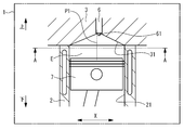
- FIG. 1 is a schematic configuration diagram of the internal combustion engine 1.
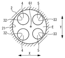
- FIG. 2 is a view of the internal combustion engine 1 taken along the line AA shown in FIG.
- the cylinder block 2 and the cylinder head 3 of the internal combustion engine 1 are shown in a cross section including a central axis P ⁇ b> 1 that is the central axis of the combustion chamber E.
- the vertical direction in the internal combustion engine 1 it is assumed that the direction along the central axis P ⁇ b> 1 is the vertical direction and the cylinder head 3 is positioned above the cylinder block 2 as shown in FIG. 1.
- a direction X shown in FIGS. 1 and 2 indicates the intake and exhaust directions of the internal combustion engine 1.
- a direction Y shown in FIG. 2 indicates the front and rear directions of the internal combustion engine 1.
- each configuration is shown in a simplified manner.
- the internal combustion engine 1 is a compression ignition type internal combustion engine, and is an internal combustion engine in which a swirl flow is generated in the combustion chamber E.
- the internal combustion engine 1 includes a cylinder block 2, a cylinder head 3, an intake valve 4, an exhaust valve 5, a fuel injection valve 6, and a piston 7.
- a cylinder 21 is formed in the cylinder block 2.
- the cylinder 21 has a central axis P1. In other words, the cylinder 21 determines the central axis P1.
- a piston 7 is accommodated in the cylinder 21.
- a cylinder head 3 is fixed to the upper part of the cylinder block 2.
- the cylinder head 3 forms a combustion chamber E together with the cylinder block 2 and the piston 7.
- the central part 31 which is a part which forms the combustion chamber E among the bottom wall parts of the cylinder head 3 has a pent roof shape.
- the pent roof shape has a top portion at a position offset in the direction X from the central axis P1 to the exhaust side.
- the central portion 31 may have a pent roof shape in which the top portion is provided in the direction X in accordance with the central axis P1 or at a position offset from the central axis P1 toward the intake side.
- the cylinder head 3 is formed with an intake port 32 and an exhaust port 33.
- An intake valve 4 and an exhaust valve 5 are provided. Both the intake port 32 and the exhaust port 33 are open to the combustion chamber E.
- the intake port 32 guides intake air to the combustion chamber E, and the exhaust port 33 exhausts the gas in the combustion chamber E.
- the intake valve 4 opens and closes the intake port 32, and the exhaust valve 5 opens and closes the exhaust port 33.
- the intake port 32 is provided with a plurality (two in this case) for the combustion chamber E together with the intake valve 4.
- a plurality (two in this case) of exhaust ports 33 are provided for the combustion chamber E together with the exhaust valve 5.
- Each intake port 32 may be an independent port that is independent from each other, or may be a part of a siamese port that is branched into the combustion chamber E and opened in the middle.
- the specific shape of each intake port 32 may be different from each other. The same applies to each exhaust port 33.
- the cylinder head 3 is further provided with a fuel injection valve 6.
- the fuel injection valve 6 injects fuel into the combustion chamber E.
- the fuel injection valve 6 includes a nozzle hole 61.
- the nozzle hole 61 is exposed at the center of the upper part of the combustion chamber E.
- the position along the direction X of the fuel injection valve 6 is set in accordance with the top of the pent roof shape that the central portion 31 has. Therefore, specifically, the fuel injection valve 6 is provided at a position offset in the direction X from the central axis P1 to the exhaust side.
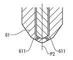
- FIG. 3 is a view showing the nozzle hole 61.
- the nozzle hole 61 is provided with a nozzle hole 611.
- the nozzle hole 61 is a part of the fuel injection valve 6 where the nozzle hole 611 is provided, and has a central axis P2.
- the nozzle hole 61 is specifically the tip of the nozzle body provided in the fuel injection valve 6.
- a plurality (eight here) of the nozzle holes 611 are provided along the circumferential direction of the nozzle hole portion 61. The number of the plurality of nozzle holes 611 can be an even number.
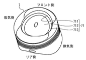
- FIG. 4 is an external view of the piston 7.
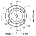
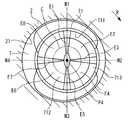
- FIG. 5 is a top view of the piston 7.
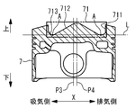
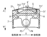
- FIG. 6 is a view of the piston 7 taken along the line BB shown in FIG.
- FIG. 7 is a view of the piston 7 taken along the line CC shown in FIG. 4 to 7 indicate the direction of the piston 7 in the internal combustion engine 1 by displaying the intake side, the exhaust side, the front side, and the rear side in addition to the vertical direction, the direction X, and the direction Y in the internal combustion engine 1 described above.
- the piston 7 will be described while also considering the state in the internal combustion engine 1. For this reason, also in the description shown below, the piston 7 will be described according to these indications as necessary.
- the piston 7 has a cavity 71.
- the cavity 71 is provided at the top of the piston 7. For this reason, the cavity 71 is exposed to the combustion chamber E in the internal combustion engine 1.
- the position along the direction X of the cavity 71 is set according to the fuel injection valve 6.
- the cavity 71 is provided at a position offset from the central axis P3, which is the central axis of the piston 7, to the exhaust side in the direction X.
- the piston 7 is provided in the internal combustion engine 1 so that the central axis P3 is disposed at the same position as the central axis P1.
- the same thing includes a case where they are different from each other within a range of manufacturing error.
- the same thing can include the case where it is different within the range which can show
- the cavity 71 includes a peripheral edge portion 711, a bottom wall surface 712, and an intermediate portion 713.
- the peripheral edge 711 has a cylindrical shape.
- the peripheral edge 711 is not necessarily limited to a cylindrical shape, and may have a cylindrical shape such as an ellipse, for example.
- the peripheral edge 711 has a central axis P4 that is the central axis of the cavity 71. In other words, the peripheral edge 711 determines the central axis P4.
- the central axis P4 extends along the central axis P3.
- the central axis P4 also corresponds to the rotational central axis of the swirl flow in the cavity 71.
- the central axis P4 is set at a position offset in the direction X to the exhaust side from the central axis P3.
- the central axis P4 is set to be disposed at the same position as the central axis P2 in the internal combustion engine 1.
- the bottom wall surface 712 has a raised shape. The shape is axisymmetric with respect to the central axis P3 and is symmetrical with respect to the central axis P4.
- the bottom wall surface 712 shares the peripheral edge 711 and the central axis P4.
- the bottom wall surface 712 does not necessarily have to share the peripheral edge 711 and the central axis P4.
- the intermediate portion 713 is provided between the peripheral edge portion 711 and the bottom wall surface 712 and connects the peripheral edge portion 711 and the bottom wall surface 712.
- the intermediate portion 713 includes an adjacent portion A adjacent to the bottom wall surface 712.
- the bottom wall surface 712 is adjacent to each other on each side of the piston 7 including the central axis P4 (for example, the cross section shown in FIG. 6 or 7) with the central axis P4 interposed therebetween. It is provided so as to protrude from the height at which the part A is provided.
- the heights of the adjacent portions A sandwiching the central axis P4 are specifically the same.
- each of the adjacent portions A sandwiching the central axis P4 is more specifically the portion having the lowest position on the surface of the cavity 71.
- the height of each of the adjacent portions A sandwiching the central axis P4 is higher in the cross section shown in FIG. 7 than in the cross section shown in FIG.
- the heights of the adjacent portions A with the central axis P4 interposed therebetween are not necessarily the same.
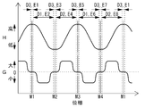
- FIG. 8 is a first diagram showing changes in various parameters.
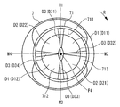
- FIG. 9 is an explanatory diagram of the bottom wall surface 712 corresponding to FIG.
- FIG. 10 is an explanatory diagram of the combustion chamber E according to FIGS.
- FIG. 8 shows the height H and the gradient G as various parameters.
- the height H is the height of the bottom wall surface 712. Specifically, the height is based on a virtual plane L (see FIGS. 6 and 7) orthogonal to the central axis P4 and positioned below the bottom wall surface 712. That's it.
- the gradient G is the gradient of the bottom wall surface 712, specifically, the gradient of the bottom wall surface 712 in the direction along the flow of the swirl flow.
- the horizontal axis shown in FIG. 8 indicates the phase (angular position) with the central axis P4 as the rotation center.
- FIG. 8 also shows a decrease portion D1, an increase portion D2, and an intermediate portion D3, which will be described later, and regions E1 to E8, which will be described later.
- the direction R shown in FIGS. 9 and 10 indicates the rotational direction of the swirl flow.
- the changes in various parameters shown in FIG. 8 are changes in the direction along the flow of the swirl flow.
- the phase M1 indicates the phase center on the front side in the phase with the central axis P4 as the rotation center.
- the phase M2 is the exhaust side of the phase
- the phase M3 is the rear side of the phase
- the phase M4 is the intake side of the phase center.
- the change in the direction along the flow of the swirl flow means the following change. That is, the locus of the swirl flow in the cavity 71 corresponds to the shape of the peripheral edge 711.
- the change in the direction along the flow of the swirl flow means a change in the direction along the outline of the peripheral edge 711.
- This change is specifically a change according to the phase centered on the central axis P4 and a change recognized along the swirl flow virtual locus C (see FIG. 10) according to the shape of the peripheral edge 711. It means that.
- the virtual locus C is a ring-shaped locus that shares the peripheral axis 711 and the central axis P4 and is similar to the outline of the peripheral edge 711 viewed along the central axis P4.
- the bottom wall surface 712 has a shape in which the height H changes in the direction along the flow of the swirl flow. Specifically, the bottom wall surface 712 is a bottom wall surface having a decreasing portion D1, an increasing portion D2, and an intermediate portion D3 described below.
- the decreasing portion D1 is provided in a section from the phase M1 to the phase M2 along the direction R and in a section from the phase M3 to the phase M4 along the direction R.
- the decrease part D11 indicates that the decrease part D1 is provided in the former section, and the decrease part D12 indicates that the decrease part D1 is provided in the latter section.
- the decreasing portion D1 is a portion where the height H decreases along the direction R.
- the increasing portion D2 is provided in the section from the phase M2 to the phase M3 along the direction R and in the section from the phase M4 to the phase M1 along the direction R.
- the increase part D21 indicates that it is an increase part D2 provided in the former section, and the increase part D22 indicates that it is an increase part D2 provided in the latter section.
- the increasing portion D2 is a portion where the height H increases along the direction R.
- the intermediate part D3 is provided corresponding to each of the phase M1, the phase M2, the phase M3, and the phase M4.
- the intermediate part D31 is an intermediate part D3 provided in correspondence with the phase M1.
- the intermediate part D32 corresponds to the phase M2
- the intermediate part D33 corresponds to the phase M3
- the intermediate part D34 corresponds to the intermediate part D3 provided corresponding to the phase M4.
- the intermediate portion D3 is adjacent to the decrease portion D1 and the increase portion D2 in the direction along the direction R, and connects the adjacent decrease portion D1 and increase portion D2.
- the intermediate portion D3 is a portion where the height H is constant in the direction along the flow of the swirl flow.
- the intermediate part D3 may be an inflection part that changes the change tendency of the height H between the adjacent decrease part D1 and increase part D2.
- the bottom wall surface 712 may have an edge portion formed by, for example, the decreasing portion D1 and the increasing portion D2 that are adjacent to each other instead of including the intermediate portion D3.
- the gradient G of the edge portion can be regarded as zero.
- the top of the bottom wall surface 712 is flat. Therefore, specifically, the bottom wall surface 712 has a shape in which the height H changes in a direction along the flow of the swirl flow in a portion other than the top portion.
- the surface of the intermediate portion 713 includes a decrease portion D1, an increase portion D2, and an intermediate portion D3.
- the bottom wall surface 712 can further be a portion including the surface of the intermediate portion 713.
- the combustion chamber E has a plurality of regions E1 to E8. Regions E ⁇ b> 1 to E ⁇ b> 8 exist on the cavity 71.
- the region E1 is a region adjacent to the intermediate part D31.
- the region E2 is in the decrease portion D11, the region E3 is in the intermediate portion D32, the region E4 is in the increase portion D21, the region E5 is in the intermediate portion D33, the region E6 is in the decrease portion D12, the region E7 is in the intermediate portion D34, and the region E8.
- regions adjacent to the increasing portion D22 are regions adjacent to the increasing portion D22.
- the region E2 and the region E6 are regions in which the angular velocity of the swirl flow that flows while being affected by the decreasing portion D1 has a downward component, and thus the angular velocity of the swirl flow is accelerated by fuel injection.
- the region E4 and the region E8 are regions in which the angular velocity of the swirl flow that flows while being influenced by the increasing portion D2 has an upward component, and as a result, the angular velocity of the swirl flow is decelerated by fuel injection.
- the region E1, the region E2, the region E4, the region E5, the region E5, the region E6, the region E8, and the region E1 have the angular velocity of the swirl flow along the direction R in the combustion chamber E during fuel injection.
- a slow region and a fast region are formed in order.
- the region E2, the region E3, the region E3, the region E4, the region E6, the region E7, the region E7, and the region E8 have the angular velocity of the swirl flow during the fuel injection in the combustion chamber E along the direction R.
- a fast region and a slow region are formed in order.
- Regions E2 where the angular velocity of the swirl flow at the time of injection is high are adjacent to the decreasing portion D11.
- the gradient G is larger in the intermediate portion D31 than in the decreasing portion D11.
- the intermediate portion D31 corresponds to a first portion
- the decrease portion D11 corresponds to a second portion.
- Regions E3 where the angular velocity of the swirl flow during injection is slow are adjacent to the intermediate portion D32.
- the gradient G is smaller in the decreasing portion D11 than in the intermediate portion D32.
- the reduced portion D11 corresponds to the second portion
- the intermediate portion D32 corresponds to the first portion.
- the regions E3 and E4 the regions E6 and E7, and the regions E7 and E8 are the regions E6 and E7, and the regions E7 and E8.
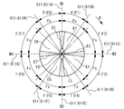
- FIG. 11 is a first explanatory view of the interval F.
- each of the plurality of nozzle holes 611 is indicated by its central axis.
- the plurality of nozzle holes 611 are provided corresponding to the region E1 to the region E8.
- a nozzle hole 611A indicates a nozzle hole 611 that injects fuel into the region E1.
- the injection hole 611B is in the region E2
- the injection hole 611C is in the region E3
- the injection hole 611D is in the region E4
- the injection hole 611E is in the region E5
- the injection hole 611F is in the region E6
- the injection hole 611G is in the region E7
- the injection hole Reference numeral 611H denotes a nozzle hole 611 for injecting fuel into the region E8.
- the interval F is a nozzle hole interval between two adjacent nozzle holes among the plurality of nozzle holes 611. Specifically, the interval F is a phase interval with the central axis P2 as the rotation center.
- the interval F1 indicates the interval F between the nozzle holes 611A and 611B.
- the distance F2 is between the nozzle holes 611B and 611C
- the distance F3 is between the nozzle holes 611C and 611D
- the distance F4 is between the nozzle holes 611D and 611E
- the distance F5 is between the nozzle holes 611E and 611F
- the distance F6 is the nozzle hole 611F.
- 611G a distance F7 between the nozzle holes 611G and 611H
- a distance F8 between the nozzle holes 611H and 611A.
- the reference interval Fs is a nozzle hole interval when a swirl flow is not generated in the combustion chamber E. Specifically, the nozzle hole interval follows each fuel spray injected from the plurality of nozzle holes 611 along the flow of the swirl flow. The nozzle hole intervals are set so as to be evenly arranged in the direction. For this reason, the reference intervals Fs are specifically equal to each other.
- the reference intervals Fs corresponding to any two intervals among the intervals F may be different from each other.
- the correspondence between the reference intervals Fs and the intervals F can be grasped as follows.
- the plurality of nozzle holes 611 are arranged so as to be symmetrical with respect to each plane including the central axis P2.
- the arrangement of the plurality of nozzle holes 611 arranged in this way is specifically one of the following first and second arrangements.
- the first arrangement is an arrangement in which the phase of any central axis of the plurality of nozzle holes 611 is set to any one of the phase M1, the phase M2, the phase M3, and the phase M4.
- the second arrangement is an arrangement in which the phase of the central axis of each of the plurality of nozzle holes 611 is set to a phase other than the phase M1, the phase M2, the phase M3, and the phase M4.
- each of the reference intervals Fs When each of the reference intervals Fs is not the same, the correspondence between each of the reference intervals Fs and each of the intervals F corresponds to one of the first and second arrangements (here, the first arrangement). This can be grasped by comparing each of the reference intervals Fs and each of the intervals F. In selecting one of the first and second arrangements, an arrangement closer to the arrangement of each of the plurality of nozzle holes 611 in which the intervals F are set can be selected. The same applies to a case where a plurality of first arrangements and second arrangements are conceivable.
- the injection holes 611A and 611B are two adjacent injection holes out of the plurality of injection holes 611, and are two injection holes that inject fuel into the region E1 and the region E2.
- the magnitude relationship between the angular velocities of the swirl flow between the region E1 and the region E2 is as described above.
- the interval F1 is set narrower than the reference interval Fs. The same applies to the interval F4, the interval F5, and the interval F8.
- the injection holes 611B and 611C are two adjacent injection holes out of the plurality of injection holes 611, and are two injection holes that inject fuel into the region E2 and the region E3.
- the magnitude relationship between the angular velocities of the swirl flow between the region E2 and the region E3 is as described above.
- the interval F2 is set wider than the reference interval Fs. The same applies to the interval F3, the interval F6, and the interval F7.
- Each of the intervals F set in this way is set based on the gradient G.
- the interval F1, the interval F4, the interval F5, and the interval F8 are set to be narrower than the reference interval Fs. For this reason, the internal combustion engine 1 can correct the position of the fuel spray transported by the swirl flow accelerated by the fuel injection to an appropriate position.
- the interval F2, the interval F3, the interval F6, and the interval F7 are set wider than the reference interval Fs. For this reason, the internal combustion engine 1 can correct the position of the fuel spray transported by the swirl flow decelerated by the fuel injection to an appropriate position.
- the internal combustion engine 1 can perform fuel injection in consideration of the angular velocity of the swirl flow during fuel injection by setting each of the intervals F in consideration of the angular velocity of the swirl flow during fuel injection. As a result, fuel can be appropriately injected into the combustion chamber E.
- the internal combustion engine 1 may include a piston 7 provided with a cavity 71 and the cavity 71 may include a bottom wall surface 712.
- the region where the angular velocity of the swirl flow during fuel injection is low is the bottom wall surface 712 between the two regions where the angular velocity of the swirl flow during fuel injection is compared among the regions E1 to E8.
- the region where the angular velocity of the swirl flow at the time of fuel injection is fast is adjacent to the second portion of the bottom wall surface 712, and the first portion has a gradient G more than the second portion.
- the internal combustion engine 1 may be configured as follows, for example.
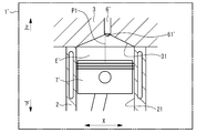
- FIG. 12 is a view showing an internal combustion engine 1 ′ which is a modification of the internal combustion engine 1.
- FIG. 13 is a view showing a piston 7 ′ which is a modification of the piston 7.
- FIG. 12 shows an internal combustion engine 1 ′ as in FIG.
- FIG. 13 shows the piston 7 ′ as in FIG.
- FIG. 13 further shows the central portion 31 and the fuel injection valve 6 ′.
- the internal combustion engine 1 ′ has a piston 7 ′ instead of the piston 7, a point having a combustion chamber E ′ instead of the combustion chamber E, and a fuel injection valve 6 ′ instead of the fuel injection valve 6, This is the same as the internal combustion engine 1.
- the piston 7 ′ is the same as the piston 7 except that a cavity 71 ′ is provided instead of the cavity 71.
- the cavity 71 ′ is the same as the cavity 71 except that the cavity 71 ′ includes a peripheral edge 711 ′, a bottom wall 712 ′, and an intermediate 713 ′ instead of the peripheral edge 711, the bottom wall surface 712, and the intermediate part 713.
- the combustion chamber E ′ is the same as the combustion chamber E except that it has a space shape corresponding to the shape of the cavity 71 ′ instead of the cavity 71.
- the peripheral edge 711 ′ is the same as the peripheral edge 711, except that the height of the lower end is constant in the direction along the flow of the swirl flow.
- the bottom wall surface 712 ′ has a raised shape like the bottom wall surface 712.
- the shape is axisymmetric with respect to the central axis P4. Specifically, the shape is a partial spherical shape.
- the bottom wall surface 712 ' has such a shape that the height H is constant in the direction along the flow of the swirl flow.
- the bottom wall surface 712 ′ has such a shape that changes the cross-sectional area S of the combustion chamber E ′ in the direction along the flow of the swirl flow.
- the cross-sectional area S is an area of a portion located on either side along the radial direction from the central axis P4 in the cross section of the combustion chamber E ′ including the central axis P4 in a state where the position of the piston 7 ′ is fixed. .
- the intermediate portion 713 ′ is the same as the intermediate portion 713 ′ except that the height is constant in the direction along the flow of the swirl flow.
- the bottom wall surface 712 ′ may be a portion further including the surface of the intermediate portion 713 ′.
- the fuel injection valve 6 ′ is the same as the fuel injection valve 6 except that the injection hole portion 61 ′ is provided instead of the injection hole portion 61.
- the nozzle hole 61 ′ is the same as the nozzle hole 61 except that each of the intervals F is set to be different from that of the internal combustion engine 1.
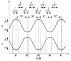
- FIG. 14 is a second diagram showing changes in various parameters.
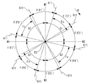
- FIG. 15 is a second explanatory diagram of the interval F.
- FIG. FIG. 14 shows the cross-sectional area S and the angular velocity V as various parameters.
- the angular velocity V is the angular velocity of the swirl flow in the internal combustion engine 1 ′.
- Changes in various parameters shown in FIG. 14 are changes in a direction along the flow of the swirl flow.
- the intervals F1 ′ to F8 ′ shown in FIG. 15 and the phase interval Q1 and the phase interval Q2 shown in FIG. 15 are shown together.
- the interval F1 ′ to the interval F8 ′ are set as the interval F in the internal combustion engine 1 ′.
- each interval F in the internal combustion engine 1 ′ is set based on the cross-sectional area S.
- the reference interval Fs is set in the internal combustion engine 1 ′ similarly to the internal combustion engine 1.
- each region in which the plurality of nozzle holes 611 injects fuel is a region in which the phase center is grasped by each phase that sets the central axis of the plurality of nozzle holes 611. For this reason, each phase which sets the space
- Each of the phases for setting the interval F2 ′ and each of the phases for setting the interval F6 ′ are set in the phase interval between the phase intervals Q2 in which the angular velocity V tends to decrease.
- Each of the phases for setting the interval F4 ′ and each of the phases for setting the interval F8 ′ are set in the phase interval between the phase intervals Q1 in which the angular velocity V tends to increase.
- the phase interval between the phase intervals Q2 means a phase interval composed of phases corresponding to the inflection points of the phase interval Q1 and the adjacent angular velocity V.
- the phase interval between the phase intervals Q1 means a phase interval constituted by the phase interval Q2 and a phase corresponding to each of the inflection points of the adjacent angular velocity V.
- the interval F2 ′ and the interval F6 ′ are the nozzle hole intervals between two adjacent nozzle holes among the plurality of nozzle holes 611, and the angular velocity V at the time of fuel injection in the combustion chamber E ′ is sequentially slow along the direction R. This is the nozzle hole interval between two nozzle holes that inject fuel into the region and the fast region.
- the interval F4 ′ and the interval F8 ′ are the nozzle hole intervals between two adjacent nozzle holes among the plurality of nozzle holes 611, and the angular velocity V at the time of fuel injection in the combustion chamber E ′ increases in order along the direction R. This is the nozzle hole interval between two nozzle holes that inject fuel into the region and the slow region.
- the phase where the angular velocity V during fuel injection is slow is a phase having a relatively large cross-sectional area S than the phase where the angular velocity V during fuel injection is fast.
- the bottom wall surface 712 ' may have a shape that is axially symmetric with respect to the central axis P4 and has a height H that changes in the direction along the flow of the swirl flow, instead of the partial spherical shape.
- each of the intervals F can be set based on the gradient G.
- each of the intervals F can be set based on at least one of the gradient G and the cross-sectional area S.
- the internal combustion engine may be a spark ignition internal combustion engine.
- the bottom wall surface is not necessarily limited to a raised shape, and may have, for example, a flat shape or a recessed shape.
- the cylinder head does not necessarily have to be manufactured with the intention of sharing or improving commonality between the spark ignition internal combustion engine and the compression ignition internal combustion engine. .
Landscapes
- Engineering & Computer Science (AREA)
- Chemical & Material Sciences (AREA)
- Combustion & Propulsion (AREA)
- Mechanical Engineering (AREA)
- General Engineering & Computer Science (AREA)
- Combustion Methods Of Internal-Combustion Engines (AREA)
Abstract
Priority Applications (5)
| Application Number | Priority Date | Filing Date | Title |
|---|---|---|---|
| EP13869903.8A EP2942506B1 (fr) | 2013-01-07 | 2013-01-07 | Moteur à combustion interne |
| JP2014555416A JP5983778B2 (ja) | 2013-01-07 | 2013-01-07 | 内燃機関 |
| US14/758,585 US20150337756A1 (en) | 2013-01-07 | 2013-01-07 | Internal combustion engine |
| CN201380069615.3A CN104903557B (zh) | 2013-01-07 | 2013-01-07 | 内燃机 |
| PCT/JP2013/050040 WO2014106904A1 (fr) | 2013-01-07 | 2013-01-07 | Moteur à combustion interne |
Applications Claiming Priority (1)
| Application Number | Priority Date | Filing Date | Title |
|---|---|---|---|
| PCT/JP2013/050040 WO2014106904A1 (fr) | 2013-01-07 | 2013-01-07 | Moteur à combustion interne |
Publications (1)
| Publication Number | Publication Date |
|---|---|
| WO2014106904A1 true WO2014106904A1 (fr) | 2014-07-10 |
Family
ID=51062227
Family Applications (1)
| Application Number | Title | Priority Date | Filing Date |
|---|---|---|---|
| PCT/JP2013/050040 Ceased WO2014106904A1 (fr) | 2013-01-07 | 2013-01-07 | Moteur à combustion interne |
Country Status (5)
| Country | Link |
|---|---|
| US (1) | US20150337756A1 (fr) |
| EP (1) | EP2942506B1 (fr) |
| JP (1) | JP5983778B2 (fr) |
| CN (1) | CN104903557B (fr) |
| WO (1) | WO2014106904A1 (fr) |
Families Citing this family (3)
| Publication number | Priority date | Publication date | Assignee | Title |
|---|---|---|---|---|
| GB2553838B (en) * | 2016-09-16 | 2020-01-29 | Perkins Engines Co Ltd | Fuel injector and piston bowl |
| JP7155918B2 (ja) * | 2018-11-16 | 2022-10-19 | マツダ株式会社 | エンジンの燃焼室構造 |
| CN112031920A (zh) * | 2020-09-11 | 2020-12-04 | 潍柴动力股份有限公司 | 柴油机燃烧系统及柴油发动机 |
Citations (4)
| Publication number | Priority date | Publication date | Assignee | Title |
|---|---|---|---|---|
| JPS62255520A (ja) * | 1986-04-30 | 1987-11-07 | Isuzu Motors Ltd | ペントル−フ形ピストン |
| JPS62255524A (ja) * | 1986-04-30 | 1987-11-07 | Isuzu Motors Ltd | ペントル−フ型直噴式内燃機関 |
| JPH11257089A (ja) | 1998-03-12 | 1999-09-21 | Toyota Motor Corp | 直噴式ディーゼル機関 |
| JP2008038650A (ja) * | 2006-08-02 | 2008-02-21 | Honda Motor Co Ltd | 燃料直噴ディーゼルエンジン |
Family Cites Families (10)
| Publication number | Priority date | Publication date | Assignee | Title |
|---|---|---|---|---|
| JP3357519B2 (ja) * | 1995-12-08 | 2002-12-16 | 株式会社クボタ | ディーゼルエンジンの直接噴射式燃焼室 |
| JP3585766B2 (ja) * | 1998-05-11 | 2004-11-04 | 本田技研工業株式会社 | ガソリン直噴エンジン |
| CN1141492C (zh) * | 2000-02-02 | 2004-03-10 | 天津大学 | 二次稀预混射流燃烧直喷式柴油机燃烧系统及其燃烧方法 |
| CN2568822Y (zh) * | 2002-09-16 | 2003-08-27 | 一拖(洛阳)柴油机有限公司 | 一种低排放的柴油机活塞燃烧室 |
| JP4757112B2 (ja) * | 2006-06-26 | 2011-08-24 | 本田技研工業株式会社 | 燃料直噴ディーゼルエンジン |
| JP4767775B2 (ja) * | 2006-07-04 | 2011-09-07 | 本田技研工業株式会社 | 燃料直噴ディーゼルエンジン |
| JP4929013B2 (ja) * | 2007-04-06 | 2012-05-09 | 本田技研工業株式会社 | 燃料直噴エンジン |
| JP4922213B2 (ja) * | 2008-03-11 | 2012-04-25 | 本田技研工業株式会社 | 燃料直噴エンジン |
| JP4732505B2 (ja) * | 2008-04-23 | 2011-07-27 | 本田技研工業株式会社 | 燃料直噴エンジン |
| WO2011059059A1 (fr) * | 2009-11-12 | 2011-05-19 | 株式会社豊田中央研究所 | Moteur diesel |
-
2013
- 2013-01-07 WO PCT/JP2013/050040 patent/WO2014106904A1/fr not_active Ceased
- 2013-01-07 US US14/758,585 patent/US20150337756A1/en not_active Abandoned
- 2013-01-07 EP EP13869903.8A patent/EP2942506B1/fr not_active Not-in-force
- 2013-01-07 CN CN201380069615.3A patent/CN104903557B/zh not_active Expired - Fee Related
- 2013-01-07 JP JP2014555416A patent/JP5983778B2/ja not_active Expired - Fee Related
Patent Citations (4)
| Publication number | Priority date | Publication date | Assignee | Title |
|---|---|---|---|---|
| JPS62255520A (ja) * | 1986-04-30 | 1987-11-07 | Isuzu Motors Ltd | ペントル−フ形ピストン |
| JPS62255524A (ja) * | 1986-04-30 | 1987-11-07 | Isuzu Motors Ltd | ペントル−フ型直噴式内燃機関 |
| JPH11257089A (ja) | 1998-03-12 | 1999-09-21 | Toyota Motor Corp | 直噴式ディーゼル機関 |
| JP2008038650A (ja) * | 2006-08-02 | 2008-02-21 | Honda Motor Co Ltd | 燃料直噴ディーゼルエンジン |
Non-Patent Citations (1)
| Title |
|---|
| See also references of EP2942506A4 |
Also Published As
| Publication number | Publication date |
|---|---|
| JPWO2014106904A1 (ja) | 2017-01-19 |
| JP5983778B2 (ja) | 2016-09-06 |
| CN104903557B (zh) | 2017-05-31 |
| US20150337756A1 (en) | 2015-11-26 |
| EP2942506B1 (fr) | 2017-08-23 |
| CN104903557A (zh) | 2015-09-09 |
| EP2942506A1 (fr) | 2015-11-11 |
| EP2942506A4 (fr) | 2015-12-30 |
Similar Documents
| Publication | Publication Date | Title |
|---|---|---|
| CN106939842A (zh) | 燃料喷射装置 | |
| CN108026880B (zh) | 发动机 | |
| JP2013113120A (ja) | 内燃機関 | |
| JP2015124659A (ja) | 火花点火式内燃機関の燃焼室構造 | |
| JP5983778B2 (ja) | 内燃機関 | |
| JP6340752B2 (ja) | 燃焼室内の流動制御装置 | |
| KR20100021487A (ko) | 통내 분사형 내연 기관 | |
| JP2014132166A (ja) | 内燃機関 | |
| JP5939318B2 (ja) | 内燃機関 | |
| WO2014106903A1 (fr) | Moteur à combustion interne | |
| US9441593B2 (en) | Fuel injection system of an internal combustion engine | |
| JP5920262B2 (ja) | 圧縮着火式内燃機関 | |
| US10711685B2 (en) | Internal combustion engine | |
| JP2014132167A (ja) | 内燃機関 | |
| JP2014134113A (ja) | 内燃機関 | |
| JPS59173554A (ja) | 燃料噴射弁 | |
| JP6028579B2 (ja) | 内燃機関 | |
| JP6564288B2 (ja) | ピストン | |
| JPS62255524A (ja) | ペントル−フ型直噴式内燃機関 | |
| CN108026881B (zh) | 发动机 | |
| JP6636836B2 (ja) | 直噴式エンジンの燃焼室構造 | |
| JP2014185526A (ja) | 圧縮着火式内燃機関 | |
| JP5862092B2 (ja) | 内燃機関 | |
| JP2019065776A (ja) | 内燃機関の燃料噴射ノズル及び内燃機関 | |
| JP2010024855A (ja) | 筒内噴射型内燃機関 |
Legal Events
| Date | Code | Title | Description |
|---|---|---|---|
| 121 | Ep: the epo has been informed by wipo that ep was designated in this application |
Ref document number: 13869903 Country of ref document: EP Kind code of ref document: A1 |
|
| ENP | Entry into the national phase |
Ref document number: 2014555416 Country of ref document: JP Kind code of ref document: A |
|
| REEP | Request for entry into the european phase |
Ref document number: 2013869903 Country of ref document: EP |
|
| WWE | Wipo information: entry into national phase |
Ref document number: 2013869903 Country of ref document: EP |
|
| WWE | Wipo information: entry into national phase |
Ref document number: 14758585 Country of ref document: US |
|
| NENP | Non-entry into the national phase |
Ref country code: DE |