WO2014109121A1 - Dispositif de mesure d'intensité de vibration et son procédé de commande - Google Patents
Dispositif de mesure d'intensité de vibration et son procédé de commande Download PDFInfo
- Publication number
- WO2014109121A1 WO2014109121A1 PCT/JP2013/080298 JP2013080298W WO2014109121A1 WO 2014109121 A1 WO2014109121 A1 WO 2014109121A1 JP 2013080298 W JP2013080298 W JP 2013080298W WO 2014109121 A1 WO2014109121 A1 WO 2014109121A1
- Authority
- WO
- WIPO (PCT)
- Prior art keywords
- value
- vibration intensity
- acceleration data
- speed value
- calculating
- Prior art date
- Legal status (The legal status is an assumption and is not a legal conclusion. Google has not performed a legal analysis and makes no representation as to the accuracy of the status listed.)
- Ceased
Links
Images









Classifications
-
- G—PHYSICS
- G01—MEASURING; TESTING
- G01V—GEOPHYSICS; GRAVITATIONAL MEASUREMENTS; DETECTING MASSES OR OBJECTS; TAGS
- G01V1/00—Seismology; Seismic or acoustic prospecting or detecting
- G01V1/01—Measuring or predicting earthquakes
-
- G—PHYSICS
- G01—MEASURING; TESTING
- G01V—GEOPHYSICS; GRAVITATIONAL MEASUREMENTS; DETECTING MASSES OR OBJECTS; TAGS
- G01V1/00—Seismology; Seismic or acoustic prospecting or detecting
- G01V1/16—Receiving elements for seismic signals; Arrangements or adaptations of receiving elements
- G01V1/18—Receiving elements, e.g. seismometer, geophone or torque detectors, for localised single point measurements
- G01V1/181—Geophones
Definitions
- the present invention relates to a vibration intensity measuring device for measuring vibration intensity and a control method thereof.
- control seismometers have been used as devices for controlling various systems according to the intensity of earthquakes and preventing the spread of damage and the occurrence of secondary disasters.
- This control seismometer measures the intensity of vibration using a measure of the intensity of seismic motion called spectrum intensity (hereinafter referred to as SI value), which has a high correlation with damage (damage) of structures.
- SI value a measure of the intensity of seismic motion
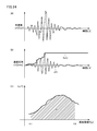
- the temporal change in acceleration y (t) is observed as shown in FIG. 24 (A), for example.
- the maximum speed value Sv (t) is the maximum value of the speed value v (t) generated up to that time.
- the spectrum distribution of the maximum velocity value Sv (t) with respect to the natural period T at such a time of vibration is as shown in FIG. 24C, and an average value of this distribution is obtained (that is, a hatched line in the figure).
- the natural period T is determined by the size of the structure and the like, and it is known that the main structure has a natural period T within the range of the integration interval (0.1 to 2.5). .
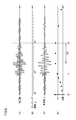
- the waveform shown in FIG. 25 is a waveform obtained by plotting time-series data of vibration acceleration y (t) detected by the acceleration detector.
- RR represents the measurement start time
- SS represents the earthquake occurrence time
- EE represents the earthquake convergence time.
- This time series data is sampled at a very short cycle (for example, 10 milliseconds) and stored in a memory (RAM).
- the time series data of the acceleration y (t) obtained so far is read from the memory.
- t [s] is the current time
- ⁇ is the integration period (time)
- T is the natural period of the structure
- h is the damping constant of the structure
- the conventional vibration intensity measurement method is constantly subjected to a calculation load (processing load) in order to always obtain a highly accurate calculation result from the occurrence of an earthquake to the convergence. For this reason, the amount of power consumed according to the calculation load also increases.
- information to be acquired as information on vibration characteristics such as earthquakes is required to detect the occurrence of an earthquake, detect whether the magnitude of the earthquake exceeds the danger level, and calculate the maximum SI value of the earthquake.
- information to be acquired as information on vibration characteristics such as earthquakes is required to detect the occurrence of an earthquake, detect whether the magnitude of the earthquake exceeds the danger level, and calculate the maximum SI value of the earthquake.
- high-precision arithmetic processing similar to that immediately after the occurrence of the earthquake is unnecessary.
- the present invention has been made to solve the above-described problems, and can perform high-precision arithmetic processing and reduce power consumption by executing more efficient arithmetic processing.
- An object of the present invention is to provide a vibration intensity measuring apparatus and a control method therefor.
- a control method of a vibration intensity measuring device includes a step of acquiring acceleration data by an acceleration detector, and a step of measuring vibration intensity based on the acquired acceleration data, and the step of acquiring and measuring At least one of the step of determining whether or not the vibration characteristics from the occurrence of vibration to the convergence thereof satisfy a predetermined condition, and the acquisition process in the step of acquiring when it is determined that the predetermined condition is satisfied; Adjusting at least one of the calculation processes in the measuring step.
- the acceleration detection unit generates acceleration data according to a variable sampling interval, and the step of adjusting adjusts the sampling interval to be longer when it is determined that a predetermined condition is satisfied.
- the acceleration detecting unit sequentially stores and acquires acceleration data in the memory, and the step of acquiring and adjusting collectively the acceleration data stored in the memory according to a variable communication interval is a predetermined condition. If it is determined that the condition is satisfied, the communication interval is set longer.
- the step of measuring the vibration intensity includes a step of calculating a speed value in each natural period based on the acquired acceleration data, and a step of calculating a maximum speed value based on the calculated speed value in each natural period;
- the step of adjusting includes reducing the number of speed values in each natural period when the maximum speed value is calculated when it is determined that the predetermined condition is satisfied.
- the step of measuring the vibration intensity includes a step of calculating a speed value based on the acquired acceleration data, a step of calculating a maximum speed value based on the calculated speed value, and a vibration based on the maximum speed value.
- the step of adjusting includes a step of calculating an index indicating the strength, and the step of adjusting sets the calculation interval of at least one of the speed value and the index indicating the vibration strength longer when it is determined that the predetermined condition is satisfied.
- the step of measuring the vibration intensity includes a step of calculating a speed value based on the acquired acceleration data, a step of calculating a maximum speed value based on the calculated speed value, and a vibration based on the maximum speed value.
- the step of adjusting includes a step of calculating an index indicating intensity, and changes a maximum speed measurement interval that is a timing for resetting the maximum speed value when it is determined that a predetermined condition is satisfied.
- the acceleration detection unit generates acceleration data for each of a plurality of axes
- the step of measuring the vibration intensity includes a step of calculating a speed value based on the acquired acceleration data, and a maximum based on the calculated speed value.
- the acceleration detection unit generates acceleration data for each of a plurality of axes
- the step of measuring the vibration intensity includes a step of calculating a speed value based on the acquired acceleration data, and a maximum based on the calculated speed value.
- a step of calculating a speed value and a step of calculating an index indicating a vibration intensity based on the maximum speed value, and the adjusting step includes a plurality of steps in the step of calculating the speed value when it is determined that a predetermined condition is satisfied. Synthesizes velocity values based on the acceleration data for each axis.
- a method for controlling a vibration intensity measuring device including an acceleration detector for a plurality of axes, the step of acquiring acceleration data of each axis by the acceleration detector, and the acquired acceleration data of each axis Measuring vibration intensity based on the step of measuring the vibration intensity, combining the acquired acceleration data of each axis, calculating a velocity value based on the combined acceleration data,
- the method includes a step of calculating a maximum speed value based on the calculated speed value, and a step of calculating an index indicating the vibration intensity based on the maximum speed value.
- a method for controlling a vibration intensity measuring device including an acceleration detection unit for a plurality of axes the step of acquiring acceleration data of each axis by the acceleration detection unit, and the acquired acceleration data of each axis Measuring the vibration intensity based on the step, the step of measuring the vibration intensity, calculating the velocity value of each axis based on the acquired acceleration data of each axis, and the calculated velocity of each axis Synthesizing values, calculating a maximum speed value based on the combined speed value, and calculating an index indicating vibration intensity based on the maximum speed value.
- a vibration intensity measurement device is a vibration intensity measurement device including an acceleration detection unit, and includes a controller connected to the acceleration detection unit.
- the controller acquires and acquires acceleration data from the acceleration detection unit. Vibration characteristics are measured based on the acceleration data, and at least one of an acquisition process for acquiring acceleration data and a calculation process for measuring the vibration intensity, It is determined whether or not a predetermined condition is satisfied, and when it is determined that the predetermined condition is satisfied, at least one of an acceleration data acquisition process and a calculation process for measuring vibration intensity is adjusted.
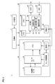
- FIG. 1 is a schematic configuration diagram of a vibration intensity measuring apparatus 1 according to the present embodiment.
- vibration intensity measuring apparatus 1 includes a sensor unit 10, an arithmetic processing unit 30, a power source unit 4, and a secondary battery 2.
- the sensor unit 10 includes an acceleration sensor 12, a sensor I / F 14, a memory 16, a sensor control unit 18, and a communication I / F 20.
- the acceleration sensor 12 is a semiconductor acceleration sensor capable of measuring three axes (X, Y, Z axes) and outputting a detection signal (acceleration detection signal) according to vibration.
- An acceleration sensor such as a capacitance type, a piezoresistive type, a piezoelectric type, or a gas temperature distribution type can be employed.
- an acceleration sensor capable of measuring three axes will be described.
- the present invention is not limited to three axes, and may be one axis, two axes, or a configuration capable of detecting multiple axes (three axes or more). Also good.
- the sensor I / F 14 is a sensor interface that samples the detection signal output from the acceleration sensor 12 at every ⁇ t and outputs acceleration data (A / D conversion), and stores acceleration data in the memory 16. To do.
- the sensor control unit 18 is a part that controls the entire sensor unit 10, and in this example, in accordance with an instruction from the arithmetic processing unit 30, a sampling interval of a detection signal that is an output of the acceleration sensor 12 (hereinafter also referred to as a sampling interval). ) Can be adjusted (variable).
- the communication I / F 20 is an interface for exchanging communication with the arithmetic processing unit 30.
- the sensor control unit 18 instructs the memory 16 to transmit the acceleration data stored in the memory 16 to the arithmetic processing unit 30 via the communication I / F 20. It is assumed that the communication interval for transmitting data from the sensor unit 10 to the arithmetic processing unit 30 can be adjusted according to an instruction from the arithmetic processing unit 30.
- the sensor control unit 18 receives input of control data from the arithmetic processing unit 30 via the communication I / F 20.
- various parameter adjustment processes in the sensor unit 10 are executed in accordance with parameter adjustment instructions from the arithmetic processing unit 30. Specifically, parameters relating to acquisition of acceleration detection signals in the sensor I / F 14 are adjusted according to control data from the arithmetic processing unit 30. Specifically, the sampling interval for sampling the acceleration detection signal is adjusted. Further, parameters related to the communication processing for the arithmetic processing unit 30 of the acceleration data via the communication I / F 20 are adjusted according to the control data from the arithmetic processing unit 30. Specifically, the communication interval of acceleration data is adjusted.
- the arithmetic processing unit 30 receives a real-time clock (RTC) 32, a memory 34, and various data as timekeeping means, and performs central processing for calculating various vibration characteristic values and outputting digital (binary) format discrimination signals.
- a control unit 40 such as a device (CPU), a digital output interface DOIF 36 that outputs a discrimination signal to the outside, a digital input interface DIIF 38 to which an external control signal is input, and a communication I / F 50 are included. Each unit is assumed to be connected to the control unit 40.
- the memory 34 stores programs for realizing various functions executed by the control unit 40, and functions such as arithmetic processing described later are realized by reading the programs.
- the memory 34 can also be used as a working area for storing the calculation result of the control unit 40 and the like.
- the control unit 40 in this example includes an SI value calculation unit 42 that calculates an SI value that is one measure of the intensity of seismic motion realized by executing a program, a speed calculation unit 46 that calculates a speed, and a maximum speed. And a maximum speed calculation unit 44 that calculates Further, although not shown in the figure, functions necessary for controlling other vibration intensity measuring devices 1 are realized.
- a vibration intensity measuring device for measuring earthquake vibration will be described.
- the present invention is not limited to earthquake vibration, and can be similarly applied to various vibration measurements.
- the communication I / F 50 is an interface for exchanging communication with the sensor unit 10.
- the control unit 40 can transmit and receive control data to and from the sensor unit 10 via the communication I / F 50.
- the control unit 40 can receive an input of acceleration data transmitted from the sensor unit 10 via the communication I / F 50 and execute a predetermined calculation process.
- the vibration intensity measuring device 1 includes a power supply unit 4 that receives supply of power from the secondary battery 2, and the power supply unit 4 supplies a voltage necessary for driving the sensor unit 10 and the arithmetic processing unit 30. .
- the power supply unit 4 operates by receiving power from the secondary battery 2
- the present invention is not limited to this case, and operates by receiving power from an external power source. It is good also as a structure.
- a configuration using a primary battery or the like is not limited to a secondary battery.
- the digital input interface (DIIF) 38 is connected to an external equipment device and receives an input from the equipment device.
- the digital output interface (DOIF) 36 is connected to an external equipment device and instructs the equipment device to operate.
- the vibration intensity measuring device 1 is provided in the gas supply system and the emergency shutoff valve is controlled according to the signal output from the vibration intensity measuring device 1 to stop the gas supply will be described. To do.
- the vibration intensity measuring device 1 is not particularly applied only to the gas supply system, but can be applied to various systems.
- attachment is easy and a use application is various.
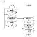
- FIG. 2 is a flowchart for explaining an example of the outline of the processing flow of vibration intensity measuring apparatus 1 according to the present embodiment.
- the sensor unit 10 is assumed to be in the standby mode (step S2). It is assumed that the sensor unit 10 is set in a low power consumption standby mode in the initial state. When it is determined that an earthquake has occurred, the operation mode is assumed to be entered. Specifically, in this example, the sensor I / F 14 samples the detection signal (acceleration detection signal) that is the output of the acceleration sensor 12 at a long sampling interval in the standby mode. And the process which stores acceleration data in the memory 16 is performed.
- the detection signal acceleration detection signal
- the sensor unit 10 determines whether or not the acceleration data stored in the memory 16 exceeds a threshold value (step S4).
- the threshold value is set to a value that is highly likely to be an earthquake when the threshold value is exceeded.
- the sensor control unit 18 compares the acceleration data stored in the memory 16 with data serving as a threshold, and determines whether the acceleration data exceeds the threshold.
- step S4 when the sensor unit 10 determines that the acceleration data exceeds the threshold value (YES in step S4), the process proceeds to step S6.
- step S4 determines in step S4 that the acceleration data does not exceed the threshold value (NO in step S4), the process returns to step S2.
- acceleration data that does not exceed the threshold value it is determined that it is the influence of noise or disturbance, and the standby mode is maintained.
- step S6 the sensor unit 10 outputs an activation signal.
- the sensor control unit 18 outputs (notifies) an activation signal to the arithmetic processing unit 30 via the communication I / F 20.
- the sensor unit 10 shifts to an operation mode (step S8). Specifically, the operation mode is shifted from the standby mode. In this operation mode, the detection signal that is the output of the acceleration sensor 12 is sampled at a short sampling interval. And the process which stores acceleration data in the memory 16 is performed.
- the sensor unit 10 determines whether or not the processing is completed (step S10). Specifically, the sensor control unit 18 determines whether or not the processing is completed according to the acceleration data stored in the memory 16, that is, whether or not the earthquake motion has converged. For example, the determination may be made according to whether or not the acceleration data is below a threshold value.
- step S10 if the sensor unit 10 determines that the process has not been completed (NO in step S10), the process returns to step S8 and maintains the operation mode of step S8.
- step S10 determines in step S10 that the process has been completed (YES in step S10), it returns to step S2 again, shifts to the standby mode, and returns to the initial initial state.
- the arithmetic processing unit 30 receives an activation signal output from the sensor unit 10 (step S12).
- the arithmetic processing unit 30 is activated according to the accepted activation signal, and first executes acquisition processing (step S14). Specifically, the acceleration data transmitted from the sensor unit 10 is acquired by communicating with the sensor unit 10. Details of the acquisition process will be described later.
- the arithmetic processing unit 30 executes arithmetic processing based on the acquired data (step S16). Details of the arithmetic processing will be described later.
- the arithmetic processing unit 30 determines whether or not the processing has been completed (step S18). Specifically, it is determined whether or not the SI value calculation processing for all acquired acceleration data has been completed.
- step S18 the arithmetic process part 30 memorize
- the calculation result stored in the memory at this time may be output to a management device or the like of a higher system.
- the process ends (end). That is, it is assumed that the activation is finished and the mode is shifted to the power saving mode. Power consumption can be reduced by this processing.
- step S18 if it is determined in step S18 that the processing unit 30 has not completed the processing (NO in step S18), the processing returns to step S14 and repeats the above acquisition processing and arithmetic processing.
- FIG. 3 is a diagram illustrating the flow of the acquisition process of arithmetic processing unit 30 according to the present embodiment.
- the processing is mainly processing in the control unit 40.
- Step S30 it is first determined whether or not the communication interval s has elapsed (step S30).
- Step S30 is maintained until the communication interval s has elapsed.
- the calculation of the period can be measured according to the clock from the RTC 32. The same applies to other periods. Note that it is not essential to use the clock of the RTC 32 for the calculation of the period, and the measurement may be performed using other means.
- step S30 when it is determined that the communication interval s has elapsed (YES in step S30), the sensor unit 10 communicates with and acquires acceleration data (step S32).
- the acquired acceleration data is stored in the memory 34.
- acceleration determination processing is executed for the acquired acceleration data (step S34). Specifically, it is determined whether or not a predetermined condition is satisfied for the acceleration data.
- the determination process will be described later. In this example, the case where the acceleration determination process is executed after acquiring the acceleration data is described. However, the determination process is not necessarily executed, and the process is terminated after the acceleration data is acquired. May be.
- FIG. 4 is a diagram illustrating a flow of arithmetic processing of arithmetic processing unit 30 according to the present embodiment. This process is a process mainly executed by the speed calculation unit 46, the maximum speed calculation unit 44, and the SI value calculation unit 42 of the control unit 40.
- a speed calculation process for calculating a speed value based on the acceleration data is executed (step S40).
- the calculation process is executed by the speed calculation unit 46 of the control unit 40.
- a speed calculation method for example, it can be obtained by an integration method based on Equation (1).
- a speed determination process for determining the calculated speed value is executed (step S41). Specifically, it is determined whether or not a predetermined condition is satisfied for the calculated speed value.
- the determination process will be described later. In this example, the case where the speed determination process is executed after the speed value is calculated is described. However, it is not always necessary to execute the determination process. After the speed value is calculated, the determination process is skipped. You may do it.
- a maximum speed calculation process for calculating a maximum speed value based on the calculated speed value is executed (step S42).
- the calculation process is executed by the maximum speed calculation unit 44 of the control unit 40.
- Equation (2) can be used as a method for calculating the maximum speed value.
- a maximum speed determination process for determining the calculated maximum speed value is executed (step S43). Specifically, it is determined whether or not a predetermined condition is satisfied for the calculated maximum speed value.
- the determination process will be described later. In this example, the case where the maximum speed determination process is executed after the maximum speed value is calculated is described. However, the determination process is not necessarily executed. After the maximum speed value is calculated, the determination process is performed. May be skipped.
- SI value calculation processing for calculating the SI value based on the maximum speed value is executed (step S44).
- the calculation process is executed by the SI value calculation unit 42 of the control unit 40.
- Equation (3) can be used as a method for calculating the SI value.
- SI value determination processing for determining the calculated SI value is executed (step S45). Specifically, it is determined whether or not the calculated SI value satisfies a predetermined condition.
- the determination process will be described later. In this example, the SI value determination process is executed after the SI value is calculated. However, the determination process is not necessarily executed. After the SI value is calculated, the determination process is skipped. Then, the processing may be terminated.
- FIG. 5 is a diagram for explaining a general flow of determination processing according to the present embodiment. Referring to FIG. 5, it is determined whether or not a predetermined condition is satisfied, for example, whether or not a trigger that is a predetermined condition is exceeded (step S ⁇ b> 46).
- step S46 If it is determined in step S46 that the trigger has been exceeded (YES in step S46), the parameter is adjusted (step S47).
- parameters used in an acquisition process for acquiring acceleration data or an arithmetic process such as an SI value are adjusted.
- the case of adjusting the parameters is described as an example, but the present invention is not limited to the parameters, and the calculation processing method, the correction method, and the like may be adjusted (changed).
- a discrimination signal is output (step S48). Specifically, a determination signal indicating that the trigger has been exceeded is output. Note that the output of the determination signal is not essential, and can be output as necessary.
- the process ends (return).
- the determination process it is determined whether or not predetermined conditions are satisfied for various values such as acceleration, speed value, maximum speed value, and SI value.
- This determination processing is described as an example in the flowcharts of FIGS. 3 and 4 described above, but as described above, this determination processing does not necessarily have to be passed.
- FIG. 4 a combination in which the determination process in step S41 is performed but the determination process in step S43 is not performed may be employed.
- the SI value determination process and the maximum speed determination process will be mainly described among the determination processes.
- FIG. 6 is a diagram for explaining predetermined conditions used in the determination process of the present embodiment.
- SI values calculated by the arithmetic processing unit 30 over time are shown.
- the vertical axis indicates the SI value, and the horizontal axis indicates time t.
- a threshold value Tr1 is provided as the SI value threshold value.
- the operation mode is switched between when the SI value is equal to or less than the threshold value Tr1 and when the SI value exceeds the threshold value Tr1.
- the threshold value Tr1 is used for discrimination when the gas supply system is stopped by controlling the emergency shutoff valve of the gas supply system, for example, when the vibration intensity measuring device 1 is arranged in the gas supply system. Shall be. That is, the threshold value Tr1 is used as a threshold value for detecting whether or not the magnitude of the earthquake exceeds the danger level.
- an urgent discrimination signal is output from the vibration intensity measuring device 1 to the emergency shutoff valve. Then, the emergency shutoff valve receives the signal and stops the gas supply.
- a threshold value Tr2 is provided as a threshold value for a period during which the SI value is not updated.
- the operation mode is switched between the case where the period during which the SI value is not updated is equal to or less than the threshold Tr2, and the case where the period during which the SI value is not updated exceeds Tr2.
- the threshold value Tr2 is used as, for example, a determination condition when the earthquake motion converges.
- the maximum speed value calculated by the arithmetic processing unit 30 is shown as time passes.
- the vertical axis represents the maximum speed value Sv, and the horizontal axis represents time t.
- a threshold value Tr3 is provided as a threshold value for a period during which the maximum speed value Sv is not updated.
- the operation mode is switched between the case where the maximum speed value Sv is not updated during the threshold Tr3 or less and the case where the maximum speed value Sv is not updated exceeds the threshold Tr3. .
- the threshold value Tr3 is used as a determination condition when the ground motion converges, for example, similarly to the threshold value Tr2.
- FIG. 7 is a diagram for explaining the flow of determination processing of the arithmetic processing unit 30 according to the present embodiment.
- the processing is mainly processing in the control unit 40.
- step S60 it is determined whether or not the threshold value Tr3 is exceeded as a threshold value for a period during which the maximum speed value Sv is not updated.
- step S60 If it is determined in step S60 that the maximum speed value Sv has exceeded the threshold value Tr3 of the period during which the maximum speed value Sv is not updated, the parameter is adjusted (step S62). The parameter adjustment will be described later.
- step S60 if it is determined in step S60 that the maximum speed value Sv does not exceed the threshold value Tr3 of the period in which the maximum speed value Sv is not updated, step S60 is skipped and the process is terminated (return).
- Step S50 it is determined whether or not the SI value exceeds the threshold value Tr1 (step S50).
- step S50 If it is determined in step S50 that the SI value has exceeded the threshold value Tr1, the parameter is adjusted (step S52). The parameter adjustment will be described later.
- a discrimination signal is output (step S53). Specifically, the emergency cutoff valve is controlled to output a determination signal for stopping the gas supply. For example, it is assumed that the determination signal is output from the control unit 40 via the DOIF 36. In this example, the case where the process of step S53 is executed has been described, but the determination signal may not be output depending on the system.
- step S50 determines whether the SI value does not exceed the threshold value Tr1 or not exceed the threshold value Tr1 or not exceed the threshold value Tr1 if it is determined in step S50 that the SI value does not exceed the threshold value Tr1, the above steps S52 and S53 are skipped and the process proceeds to step S54.
- step S54 it is determined whether or not the threshold value Tr2 has been exceeded as a threshold value for the period in which the SI value is not updated.
- step S54 If it is determined in step S54 that the threshold value Tr2 during which the SI value is not updated has been exceeded, the parameter is adjusted (step S56). The parameter adjustment will be described later.
- step S54 determines whether the threshold value Tr2 of the period during which the SI value is not updated is not exceeded. If it is determined in step S54 that the threshold value Tr2 of the period during which the SI value is not updated is not exceeded, step S56 is skipped and the process is terminated (return).
- the present invention is not particularly limited to this configuration, and any configuration that includes one of the predetermined conditions may be used. . Alternatively, it is also possible to provide a plurality of conditions.
- the flow of the SI value determination process and the maximum speed determination process has been described mainly in the above determination process, but it is also determined whether the predetermined condition is satisfied in the other determination process flows as well. If so, adjust the parameters.
- FIG. 8 is a diagram illustrating adjustment of parameters in the operation mode of the sensor unit 10 according to the present embodiment.
- the sampling interval g when shifting to the operation mode is assumed to be g0 (0.01 s). That is, sampling is performed at a short sampling interval. Then, the acceleration data is stored in the memory 16.
- the arithmetic processing unit 30 acquires acceleration data as described above, executes arithmetic processing, and repeats the processing.
- the SI value is calculated by arithmetic processing.
- the arithmetic processing unit 30 instructs the sensor unit 10 to adjust parameters so as to adjust the sampling interval. Specifically, the sampling interval is instructed to be set to g1 (0.02 s).
- the acceleration detection signal is sampled according to the sampling interval g 1 and acceleration data is stored in the memory 16.
- the determination signal is output to the emergency shutoff valve as described above. Thereby, supply of gas is stopped. Therefore, when the vibration intensity measuring device is used in the gas supply system, it is not necessary to further output urgent information after the determination signal is output (after the gas supply is stopped). Conceivable. In other words, since highly accurate measurement is not often required, low power consumption can be achieved by adjusting the sampling interval to reduce the calculation load.
- the arithmetic processing unit 30 instructs the sensor unit 10 to adjust parameters so as to adjust the sampling interval. Specifically, the sampling interval is instructed to be set to g2 (0.04 s).
- the acceleration detection signal is sampled according to the sampling interval g2 and the acceleration data is stored in the memory 16 in the period after time t2.
- FIG. 9 is a diagram illustrating adjustment of parameters of communication processing between the sensor unit 10 and the arithmetic processing unit 30 according to the present embodiment.
- the arithmetic processing unit 30 acquires acceleration data as described above, executes arithmetic processing, and repeats the processing.
- the SI value is calculated by arithmetic processing.
- the arithmetic processing unit 30 instructs the sensor unit 10 to adjust parameters so as to adjust the communication interval. Specifically, the communication interval s is instructed to be set to s1 (> s0).
- Acceleration data communication processing is executed with the arithmetic processing unit 30 according to the communication interval s1 in a period after the time t1 according to the instruction.
- the determination signal is output to the emergency shutoff valve as described above. Therefore, it is considered that it is not necessary to further output urgent information after the determination signal is output (after the gas supply is stopped). That is, since it is a situation where highly accurate measurement is not required, low power consumption can be achieved by adjusting the communication interval to reduce the communication load.
- the arithmetic processing unit 30 instructs the sensor unit 10 to adjust parameters so as to adjust the communication interval. Specifically, the communication interval s is instructed to be set to s2 (> s1).
- Acceleration data communication processing is executed with the arithmetic processing unit 30 according to the communication interval s2 in a period after time t2 in accordance with the instruction.
- the SI value exceeds the threshold value Tr2 during which the SI value is not updated, it is considered that the earthquake motion converges as described above. Therefore, since highly accurate measurement is not required, it is possible to further reduce power consumption by adjusting the communication interval to suppress the communication load.
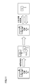
- FIG. 10 is a diagram illustrating adjustment of the number of natural periodic velocities in the arithmetic processing of arithmetic processing unit 30 according to the present embodiment.
- speed values v (T1) to v (Tn) according to the natural period T are calculated based on the acceleration data a, respectively, and the maximum values are calculated based on the calculated speed values v (T1) to v (Tn).
- velocity values Sv (T1) to Sv (Tn) are calculated, and SI values are calculated based on the maximum velocity values Sv (T1) to Sv (Tn).
- FIG. 10 (B) here, the acceleration data and the adjustment of the arithmetic processing according to the passage of time are schematically shown.
- the arithmetic processing unit 30 adjusts parameters for arithmetic processing. Specifically, in the period after time t1, the maximum speed value Sv is calculated by setting the number n of natural period speeds to be calculated to n1 (9).
- the determination signal is output to the emergency shutoff valve as described above. Therefore, it is considered that it is not necessary to further output urgent information after the determination signal is output (after the gas supply is stopped). That is, since it is a situation where highly accurate measurement is not required, it is possible to reduce power consumption by adjusting the number of data to be used and suppressing the calculation load.
- the SI value calculated by the arithmetic processing unit 30 exceeds the threshold value Tr2 of the period during which the SI value is not updated at time t2. That is, in the determination process described above, it is determined that the threshold value Tr2 of the period during which the SI value is not updated is exceeded. This adjusts the parameters.
- the arithmetic processing unit 30 adjusts parameters for arithmetic processing. Specifically, in the period after time t2, the maximum speed value is calculated by setting the number n of natural period velocities to be calculated to n2 (eight).
- the SI value exceeds the threshold value Tr2 during which the SI value is not updated, it is considered that the earthquake motion converges as described above. Therefore, since highly accurate measurement is not often required, it is possible to further reduce power consumption by adjusting the number of data to be used and suppressing the calculation load.
- FIG. 11 is a diagram illustrating a method for storing the maximum speed value according to the present embodiment.
- the first calculated speed value v is set as the maximum speed value Sv and stored. Thereafter, each time the speed value v is calculated, the absolute value is compared with the maximum speed value Sv, and if the speed value v updates the maximum speed value Sv based on the comparison result, the speed value v is updated. Then, the process is repeated.
- the maximum speed value Sv is stored as the maximum speed in the earthquake, that is, the maximum earthquake speed value SSv. To do. Then, the maximum speed value is set to the initial value 0.
- the calculated speed value v is set to the maximum speed value Sv, and thereafter, every time the speed value v is calculated, the absolute value and the maximum speed value Sv are compared, and the speed value v is determined based on the comparison result. If the maximum speed value Sv is updated, it is updated. Then, after the indefinite time has elapsed, the process is repeated.
- the maximum velocity value Sv can be saved as the earthquake maximum velocity value SSv. Therefore, the earthquake maximum velocity value SSv can be stored and important information can be held. In addition, it is not necessary to store all speed values, and the maximum value is stored, so that the amount of memory can be reduced. Further, power consumption can be reduced as the amount of memory is reduced.
- the earthquake maximum velocity value SSv can be updated.
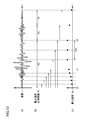
- FIG. 12 is a diagram illustrating adjustment of the maximum speed value measurement interval in the arithmetic processing of the arithmetic processing unit 30 according to the present embodiment.
- the maximum speed measurement interval: R is a timing for resetting the maximum speed, and the maximum speed value Sv is reset to the initial value 0 for each maximum speed measurement interval R.
- R0 is set to the time until the period exceeds the threshold value Tr3.
- the speed value v is obtained from the acceleration data, the calculated speed value v is compared with the maximum speed value Sv, and if the speed value v has updated the maximum speed value Sv based on the comparison result, an update process is performed. Execute.
- the arithmetic processing unit 30 adjusts parameters for arithmetic processing. Specifically, in the period after time t3, the interval for measuring the maximum speed value, that is, the section R is set to the section R1 (for example, 10 seconds). Further, since the period exceeds the threshold value Tr3, that is, since R0 has elapsed, the maximum speed value Sv is reset to the initial value 0.
- the speed value v is obtained again from the acceleration data, the calculated speed value v is compared with the maximum speed value Sv, and updated if the speed value v updates the maximum speed value Sv based on the comparison result. Execute the process. Then, when R1 (for example, 10 seconds) elapses, the maximum speed value Sv is reset to the initial value 0. Then, the process is repeated.
- interval R for measuring the maximum velocity value may be a fixed value set in advance, or may be set in association with other calculation intervals such as acceleration, velocity, SI value, and the like.
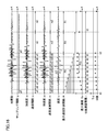
- FIG. 13 is a diagram illustrating adjustment of the calculation interval in the calculation processing of the calculation processing unit 30 according to the present embodiment.
- the arithmetic processing unit 30 adjusts parameters for arithmetic processing. Specifically, in a period after time t1, a speed calculation interval m that is an interval for calculating a speed value is set to m1 (> m0). In the period after time t1, the SI value calculation interval I, which is an interval for calculating the SI value, is set to I1 (> I0).
- the calculation processing unit 30 executes speed value calculation processing according to the speed calculation interval m1. In accordance with the instruction, in the period after time t1, the calculation processing unit 30 executes speed value calculation processing in accordance with the SI value calculation interval I1.
- the determination signal is output to the emergency shutoff valve as described above. Therefore, it is considered that it is not necessary to further output urgent information after the determination signal is output (after the gas supply is stopped). That is, since it is a situation where highly accurate measurement is not required, low power consumption can be achieved by adjusting the interval for calculating the speed value to suppress the calculation load.
- the arithmetic processing unit 30 adjusts parameters for arithmetic processing. Specifically, in a period after time t3, a speed calculation interval m, which is an interval for calculating a speed value, is set to m2 (> m1). In the period after time t3, the SI value calculation interval I, which is an interval for calculating the SI value, is set to I2 (> I1).
- the calculation processing unit 30 executes speed value calculation processing according to the speed calculation interval m2. Further, in the period after time t3 in accordance with the instruction, the calculation processing unit 30 executes speed value calculation processing in accordance with the SI value calculation interval I2.
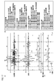
- FIG. 14 is a diagram illustrating a specific example of the adjustment processing table of the vibration intensity measurement device according to the present embodiment.
- FIG. 14A shows a condition table in which predetermined conditions (trigger conditions) are defined.
- FIG. 14B shows an adjustment parameter table for adjustment processing.
- the sampling interval g0 (0.01 s), the communication interval s0 (1 s), the number of natural frequency velocities n0 (7), the maximum speed measurement interval R0 (until the condition of Tr3 is satisfied), and the speed calculation interval m0 (1s), the adjustment parameter of the SI value calculation interval 10 (1s) is shown.
- the sampling interval g1 (0.02 s), the communication interval s1 (5 s), the number n1 (6) of each natural cycle speed, and the maximum speed measurement interval R0 (Tr3 conditions are set)
- Adjustment parameters to be adjusted to a speed calculation interval m1 (1 s) and an SI value calculation interval l1 (until the condition of Tr3 is satisfied) are shown.
- the sampling interval g2 (0.04 s), the communication interval s2 (10 s), the number n2 (5) of each natural period speed, and the maximum speed measurement Adjustment parameters to be adjusted to an interval R1 (10 s), a speed calculation interval m2 (10 s), and an SI value calculation interval l2 (until convergence) are shown.
- FIG. 15 is an example of adjusting the parameters of the sensor unit 10 and the arithmetic processing unit 30 according to the table of FIG.
- the sampling interval g1 (0.02 s), the communication interval s1 (5 s), and the number n1 (6) of each natural cycle speed according to the table of FIG. 14B.
- the maximum speed measurement interval R0 (until the condition of Tr3 is satisfied), the speed calculation interval m1 (5 s), and the SI value calculation interval l1 (until the condition of Tr3 is satisfied) are adjusted.
- the sampling interval g2 (0.04 s), the communication interval s2 (10 s), each The number of natural period velocities is adjusted to n2 (5), maximum speed measurement interval R1 (10 s), speed calculation interval m2 (10 s), and SI value calculation interval l2 (until convergence).
- FIG. 16 is another diagram for adjusting the parameters of the sensor unit 10 and the arithmetic processing unit 30 in accordance with the table of FIG.
- the sampling interval g2 (0.02 s), the communication interval s2 (10 s), each The number of natural period velocities is adjusted to n2 (5), maximum speed measurement interval R1 (10 s), speed calculation interval m2 (10 s), and SI value calculation interval l2 (until convergence).
- various parameters can be adjusted according to the state of earthquake motion.
- the accuracy until the predetermined condition is satisfied after the seismic motion occurs is detected.
- a high measurement or the like is performed and a predetermined condition is satisfied, it is possible to realize an operation with low power consumption by suppressing a calculation load and a communication load.
- FIG. 17 is a diagram illustrating a predetermined condition (trigger condition).
- a predetermined condition Trigger condition.
- acceleration values (1) a certain acceleration value, (2) an increase rate of acceleration, (3) time until exceeding a certain acceleration, (4) certain acceleration Duration when acceleration is exceeded, (5) Number of times a certain acceleration is exceeded, (6) Duration when certain acceleration is not exceeded, (7) Duration of acceleration from earthquake occurrence to convergence Can be used.
- a certain speed value (9) the rate of increase in speed, (10) the time until it exceeds a certain speed, (11) continuation when it exceeds a certain speed It is possible to use the time, (12) the number of times that a certain speed has been exceeded, (13) the duration when the speed does not exceed a certain speed, and (14) the speed duration from the occurrence of the earthquake to convergence. is there.
- the maximum speed value (15) a certain maximum speed value, (16) an increase rate of the maximum speed, (17) a time until the certain maximum speed is exceeded, and (18) a certain maximum speed. Duration when exceeded, (19) number of times a certain maximum speed has been exceeded, (20) duration when not exceeding a certain maximum speed, (21) time when maximum speed is not updated, (22) It is possible to use the number of times the maximum speed is not updated.
- SI value (3) a certain SI value, (24) the rate of increase of the SI location, (25) time until exceeding a certain SI value, (26) exceeding a certain SI value Time duration, (27) number of times a certain SI value has been exceeded, (28) duration time when the certain SI value has not been exceeded, (29) time the SI value is not updated, (30) SI value It is possible to use the number of times that is not updated.
- predetermined condition is not limited to the increase rate, and for example, the change rate can be included in the predetermined condition. Further, the above is an example, and it is naturally possible to provide other conditions.
- determining whether one condition is satisfied as a predetermined condition it may be determined whether a plurality of conditions are satisfied. For example, you may make it determine whether both conditions are satisfy
- condition A After satisfying a certain condition A, it may be determined that the condition is satisfied when another condition B is satisfied, or when the condition A or B is satisfied, it is determined that the condition is satisfied You may do it.
- condition B if the condition B is satisfied within a certain time after the condition A is satisfied, it may be determined that the condition is satisfied, or it may be determined that the condition is satisfied when the condition is not satisfied within a certain time. It is possible to execute highly accurate determination processing by appropriately combining the above conditions according to the characteristics of earthquake motion.
- acceleration data is stored in the memory 34 in units of 2 bytes. It is possible to store acceleration values from ⁇ 32768 to 328767 (gal).
- the acceleration value is a small value. Since it is considered that there is, the acceleration data is switched to be stored in the memory 34 in units of 1 byte. It is also possible to further reduce power consumption by changing the amount of data stored in the memory 34 according to the state of earthquake motion by this method. Further, when storing in the memory, it may be stored in the memory in a state where the resolution is increased by multiplying the acceleration value by a constant. For example, in the case of 10.5 (gal), 105 (gal), which is a value multiplied by 10 as a constant, may be stored in the memory. It is possible to reduce the load at the time of arithmetic processing while maintaining accuracy by the processing, thereby suppressing power consumption.
- the speed may be calculated based on the corrected acceleration data.
- interpolation processing may be performed on the acceleration data before calculating the speed.
- interpolation process it is possible to take an average value of two adjacent data.
- the speed before calculating the speed, it may be calculated after setting the acceleration to an integer. Alternatively, the calculation may be performed with a constant increased in resolution. It is also possible to calculate the speed after making it an integer. It is possible to reduce the calculation load by calculating to an integer.
- the calculation load may be reduced by using a time integration method or a simple equal acceleration equation.
- the priority order of the natural period speed to be selected may be determined prior to calculating the maximum speed value. Further, it may be determined which natural period is selected based on the curve of the maximum speed value Sv and the natural period T at a certain time.
- FIG. 19 is a diagram illustrating a method for calculating the SI value based on the curve of the maximum speed value Sv and the natural period T.
- the calculation load can be reduced by calculating the SI value according to the trapezoidal rule.
- the calculation load can be reduced by calculating the SI value according to the rectangular approximation.
- the inclination may be measured to correct the offset deviation.
- the timing of correcting the offset may be performed at the end of the convergence after the occurrence of the earthquake, or may be executed before the arithmetic processing unit enters the sleep state.
- the vibration intensity measuring device falls, the presence or absence of the fall or the number of drops may be stored in the memory.
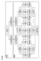
- FIG. 20 is a diagram for explaining a concept of a calculation process for calculating an SI value based on acceleration data of a plurality of axes as a comparative example.
- an acceleration sensor detects an acceleration ax of an X-axis component and an acceleration ay of a Y-axis component when an earthquake motion occurs is shown.
- acceleration data in a predetermined direction is calculated by vector decomposition based on the acceleration ax of the X-axis component and the acceleration ay of the Y-axis component.
- acceleration data in eight directions is calculated as a predetermined direction.
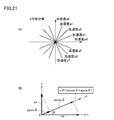
- FIG. 21 is a diagram for explaining an example of vector decomposition. Referring to FIG. 21A, here, eight directions of accelerations a0 to a7 are shown as an example.
- the angles ⁇ of the respective accelerations a0 to a7 are 90 °, 67.5 °, 45 °, 22.5 °, 0 °, 157.5 °, 135 °, and 112.5 °.
- FIG. 21B shows a case where vector decomposition is performed to an angle ⁇ in an arbitrary direction based on the acceleration ax of the X-axis component and the acceleration ay of the Y-axis component.
- the acceleration a ⁇ is represented by axcos ⁇ + aysin ⁇ .
- velocity values v (T1) to v (Tn) according to the natural period T are calculated based on the respective acceleration data for the eight directions of the vector-decomposed accelerations a0 to a7.
- Maximum speed values Sv (T1) to Sv (Tn) are calculated based on the calculated speed values v (T1) to v (Tn), and SI is calculated based on the maximum speed values Sv (T1) to Sv (Tn). The case where the value is calculated is shown.
- the maximum SI value is calculated from the SI values in the respective directions (eight directions).
- the case of calculating SI values in eight directions is described as an example, but the accuracy can be further improved by calculating SI values in a plurality of directions.
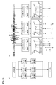
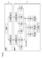
- FIG. 22 is a diagram for explaining the concept of calculation processing for calculating SI values based on multi-axis acceleration data according to the sixth modification.
- the acceleration sensor detects the acceleration ax of the X-axis component and the acceleration ay of the Y-axis component when an earthquake motion occurs.
- acceleration data are acquired in a control part, and the calculation of SI value is performed.
- velocity values v (T1) to v (Tn) according to the natural period T are calculated based on the acceleration ax of the X-axis component and the acceleration ay of the Y-axis component, respectively.
- the calculated X-axis component velocity value and Y-axis component velocity value are vector-synthesized.
- the maximum speed values Sv (T1) to Sv (Tn) are calculated based on the vector-combined speed values v (T1) to v (Tn), and the maximum speed values Sv (T1) to Sv (Tn) are calculated. The case where the SI value is calculated based on this is shown.
- FIG. 23 is a diagram for explaining the concept of calculation processing for calculating SI values based on acceleration data of a plurality of axes according to another example of the sixth modification.
- an acceleration sensor detects an acceleration ax of an X-axis component and an acceleration ay of a Y-axis component when an earthquake motion occurs is shown.
- the said acceleration data are acquired in a control part, and the calculation of SI value is performed. Specifically, the acceleration ax of the X-axis component and the acceleration ay of the Y-axis component are acquired.
- the acquired X-axis component acceleration ax and Y-axis component acceleration ay are vector-synthesized.
- the velocity values v (T1) to v (Tn) according to the natural period T are calculated based on the vector-combined acceleration data.
- maximum speed values Sv (T1) to Sv (Tn) are calculated based on the calculated speed values v (T1) to v (Tn), respectively, and based on the maximum speed values Sv (T1) to Sv (Tn). In this case, the SI value is calculated.
- the speed value described in FIG. 22 may be switched to a method of calculating the SI value by vector synthesis, or the acceleration described in FIG. It is possible to switch to a method for calculating a value.
- vibration intensity measuring device 1 vibration intensity measuring device, 2 secondary battery, 4 power supply unit, 10 sensor unit, 12 acceleration sensor, 14 sensor I / F, 16, 34 memory, 18 sensor control unit, 20, 50 communication I / F, 30 arithmetic processing Part, 40 control part, 42 SI value calculation part, 44 maximum speed calculation part, 46 speed calculation part.
Landscapes
- Physics & Mathematics (AREA)
- Life Sciences & Earth Sciences (AREA)
- Engineering & Computer Science (AREA)
- Remote Sensing (AREA)
- Acoustics & Sound (AREA)
- Environmental & Geological Engineering (AREA)
- Geology (AREA)
- General Life Sciences & Earth Sciences (AREA)
- General Physics & Mathematics (AREA)
- Geophysics (AREA)
- Geophysics And Detection Of Objects (AREA)
- Measurement Of Mechanical Vibrations Or Ultrasonic Waves (AREA)
Abstract
Selon la présente invention, un procédé de commande pour dispositif de mesure d'intensité de vibration comprend une étape d'acquisition de données d'accélération avec une unité de détection d'accélération, et une étape de mesure d'intensité de vibration sur la base des données d'accélération acquises. Au moins l'une de l'étape d'acquisition ou de l'étape de mesure comprend une étape de détermination du point de savoir si des caractéristiques de vibration durant la période depuis la génération de la vibration jusqu'à une convergence remplissent des conditions prescrites, et une étape de réglage, lorsque les conditions prescrites sont déterminées comme ayant été remplies, d'au moins l'un d'un processus d'acquisition dans l'étape d'acquisition et du processus de calcul dans l'étape de mesure.
Priority Applications (1)
| Application Number | Priority Date | Filing Date | Title |
|---|---|---|---|
| EP13871034.8A EP2944979B1 (fr) | 2013-01-11 | 2013-11-08 | Dispositif de mesure d'intensité de vibration et son procédé de commande |
Applications Claiming Priority (2)
| Application Number | Priority Date | Filing Date | Title |
|---|---|---|---|
| JP2013-003618 | 2013-01-11 | ||
| JP2013003618A JP6182867B2 (ja) | 2013-01-11 | 2013-01-11 | 振動強度測定装置およびその制御方法 |
Publications (1)
| Publication Number | Publication Date |
|---|---|
| WO2014109121A1 true WO2014109121A1 (fr) | 2014-07-17 |
Family
ID=51166786
Family Applications (1)
| Application Number | Title | Priority Date | Filing Date |
|---|---|---|---|
| PCT/JP2013/080298 Ceased WO2014109121A1 (fr) | 2013-01-11 | 2013-11-08 | Dispositif de mesure d'intensité de vibration et son procédé de commande |
Country Status (3)
| Country | Link |
|---|---|
| EP (1) | EP2944979B1 (fr) |
| JP (1) | JP6182867B2 (fr) |
| WO (1) | WO2014109121A1 (fr) |
Cited By (2)
| Publication number | Priority date | Publication date | Assignee | Title |
|---|---|---|---|---|
| CN113795735A (zh) * | 2019-05-31 | 2021-12-14 | Abb瑞士股份有限公司 | 用于监测旋转装置的方法以及状态监测设备 |
| CN116558623A (zh) * | 2023-07-05 | 2023-08-08 | 天津宜科自动化股份有限公司 | 一种基于电容测量震动程度的系统 |
Families Citing this family (15)
| Publication number | Priority date | Publication date | Assignee | Title |
|---|---|---|---|---|
| JP6565159B2 (ja) * | 2014-10-15 | 2019-08-28 | オムロン株式会社 | モニタリング装置、モニタリングシステム、およびモニタリング方法 |
| JP2017166832A (ja) * | 2016-03-14 | 2017-09-21 | オムロン株式会社 | 感震センサ及び地震検知方法 |
| JP2016205920A (ja) * | 2015-04-20 | 2016-12-08 | 株式会社ミツトヨ | 地震強度値算出システム及び地震強度値算出方法 |
| JP6528567B2 (ja) | 2015-07-02 | 2019-06-12 | オムロン株式会社 | 感震センサ及び閾値調整方法 |
| JP6666023B2 (ja) * | 2015-07-02 | 2020-03-13 | 東京瓦斯株式会社 | 感震センサ及び地震判定方法 |
| JP6560609B2 (ja) * | 2015-12-18 | 2019-08-14 | アズビル株式会社 | 地震動強度測定装置および方法 |
| DE102016109432B4 (de) * | 2016-05-23 | 2023-08-31 | Minebea Intec GmbH | Verfahren zur Kompensation von Langzeitdriften und Kriecherscheinungen an Bolzensensoren in erdbebengefährdeten Gebieten |
| JP6851150B2 (ja) * | 2016-07-11 | 2021-03-31 | リンナイ株式会社 | ガスコンロ |
| JP6737211B2 (ja) * | 2017-03-14 | 2020-08-05 | オムロン株式会社 | 感震センサ及び地震判定方法 |
| JP6857814B2 (ja) * | 2018-03-26 | 2021-04-14 | パナソニックIpマネジメント株式会社 | マイコン式ガスメーター |
| JP7347749B2 (ja) * | 2018-10-12 | 2023-09-20 | 国際先端技術総合研究所株式会社 | 状態監視装置、および状態監視システム |
| JP7469703B2 (ja) * | 2020-07-20 | 2024-04-17 | 日本電信電話株式会社 | 予測方法、学習方法、予測装置、学習装置、予測プログラム及び学習プログラム |
| JP2022183508A (ja) * | 2021-05-31 | 2022-12-13 | 株式会社フジタ | 制振装置 |
| JP2025162240A (ja) * | 2024-04-15 | 2025-10-27 | オムロン株式会社 | 感震センサおよび地震検知方法、地震検知プログラム |
| JP2025162831A (ja) * | 2024-04-16 | 2025-10-28 | オムロン株式会社 | 感震センサおよび地震検知方法、地震検知プログラム |
Citations (6)
| Publication number | Priority date | Publication date | Assignee | Title |
|---|---|---|---|---|
| JPH09318763A (ja) * | 1996-05-31 | 1997-12-12 | Matsushita Electric Ind Co Ltd | 感震装置 |
| JP2001042049A (ja) | 1999-07-30 | 2001-02-16 | Yamatake Corp | 振動強度の測定方法 |
| JP2003255052A (ja) * | 2002-03-05 | 2003-09-10 | Tokyo Gas Co Ltd | 計測震度推定装置 |
| JP2006105759A (ja) * | 2004-10-05 | 2006-04-20 | Matsushita Electric Ind Co Ltd | 感震ユニット |
| JP2009156743A (ja) * | 2007-12-27 | 2009-07-16 | Osaka Gas Co Ltd | 感震器、緊急遮断システム及び緊急遮断システムの使用方法 |
| JP2010164325A (ja) * | 2009-01-13 | 2010-07-29 | Taisei Corp | 地震動の予測システム |
Family Cites Families (4)
| Publication number | Priority date | Publication date | Assignee | Title |
|---|---|---|---|---|
| US4663628A (en) * | 1985-05-06 | 1987-05-05 | Halliburton Company | Method of sampling environmental conditions with a self-contained downhole gauge system |
| US20050226098A1 (en) * | 2004-04-07 | 2005-10-13 | Baker Hughes Incorporated | Dynamic acoustic logging using a feedback loop |
| NZ553955A (en) * | 2007-03-19 | 2008-05-30 | Commtest Instr Ltd | Method and system for vibration sensing power management |
| JP5375435B2 (ja) * | 2009-08-25 | 2013-12-25 | 株式会社ホームサイスモメータ | 震度測定装置 |
-
2013
- 2013-01-11 JP JP2013003618A patent/JP6182867B2/ja active Active
- 2013-11-08 WO PCT/JP2013/080298 patent/WO2014109121A1/fr not_active Ceased
- 2013-11-08 EP EP13871034.8A patent/EP2944979B1/fr active Active
Patent Citations (6)
| Publication number | Priority date | Publication date | Assignee | Title |
|---|---|---|---|---|
| JPH09318763A (ja) * | 1996-05-31 | 1997-12-12 | Matsushita Electric Ind Co Ltd | 感震装置 |
| JP2001042049A (ja) | 1999-07-30 | 2001-02-16 | Yamatake Corp | 振動強度の測定方法 |
| JP2003255052A (ja) * | 2002-03-05 | 2003-09-10 | Tokyo Gas Co Ltd | 計測震度推定装置 |
| JP2006105759A (ja) * | 2004-10-05 | 2006-04-20 | Matsushita Electric Ind Co Ltd | 感震ユニット |
| JP2009156743A (ja) * | 2007-12-27 | 2009-07-16 | Osaka Gas Co Ltd | 感震器、緊急遮断システム及び緊急遮断システムの使用方法 |
| JP2010164325A (ja) * | 2009-01-13 | 2010-07-29 | Taisei Corp | 地震動の予測システム |
Non-Patent Citations (1)
| Title |
|---|
| See also references of EP2944979A4 |
Cited By (3)
| Publication number | Priority date | Publication date | Assignee | Title |
|---|---|---|---|---|
| CN113795735A (zh) * | 2019-05-31 | 2021-12-14 | Abb瑞士股份有限公司 | 用于监测旋转装置的方法以及状态监测设备 |
| CN116558623A (zh) * | 2023-07-05 | 2023-08-08 | 天津宜科自动化股份有限公司 | 一种基于电容测量震动程度的系统 |
| CN116558623B (zh) * | 2023-07-05 | 2024-04-26 | 天津宜科自动化股份有限公司 | 一种基于电容测量震动程度的系统 |
Also Published As
| Publication number | Publication date |
|---|---|
| EP2944979B1 (fr) | 2019-04-10 |
| JP6182867B2 (ja) | 2017-08-23 |
| EP2944979A1 (fr) | 2015-11-18 |
| EP2944979A4 (fr) | 2016-08-17 |
| JP2014134501A (ja) | 2014-07-24 |
Similar Documents
| Publication | Publication Date | Title |
|---|---|---|
| JP6182867B2 (ja) | 振動強度測定装置およびその制御方法 | |
| KR101838053B1 (ko) | 운동 구조물의 운동 및 진동을 결정하기 위한 시스템 및 방법 | |
| JP6648515B2 (ja) | 電子機器及びその角速度取得方法、角速度取得プログラム | |
| CN110926464B (zh) | 一种基于双模式的惯性导航方法及系统 | |
| US20160101319A1 (en) | Electronic device, control program, control method, and system | |
| CN105045270A (zh) | 一种基于振动补偿与状态反馈的刚柔系统姿态控制方法 | |
| US20180111021A1 (en) | Exercise analysis device, exercise analysis system, and exercise analysis method | |
| US20160370188A1 (en) | Inertial device, control method and program | |
| JP6963275B2 (ja) | 建物被災推定システムおよび方法 | |
| US8981904B2 (en) | Compression of IMU data for transmission of AP | |
| JP2015001494A (ja) | 地震センサ装置および地震波形記録方法 | |
| US8575919B2 (en) | Inclination detection method and inclination detection apparatus | |
| KR102048861B1 (ko) | 관성센서 제어장치 및 그 방법 | |
| WO2014034403A1 (fr) | Appareil électronique et programme | |
| KR101513352B1 (ko) | 관성센서의 구동장치 및 그 제어방법 | |
| EP2645110B1 (fr) | Compression de données d'une unité de mesure inertielle pour transmission à un processeur d'application | |
| JP6432308B2 (ja) | 計測装置及び計測レンジ切換方法 | |
| CN109303565A (zh) | 一种睡眠状态的预测方法及装置 | |
| JP2015143661A (ja) | 構造物監視装置、構造物監視システム及び構造物監視方法 | |
| JP7002859B2 (ja) | 地震が起きやすい地域におけるボルトセンサの長期ドリフトおよびクリープ現象を補正する方法 | |
| JP2015143662A (ja) | 構造物監視装置、構造物監視システム及び構造物監視方法 | |
| WO2015198599A1 (fr) | Dispositif de mesure, système de mesure, procédé de mesure, et support d'enregistrement lisible par ordinateur | |
| JP6560609B2 (ja) | 地震動強度測定装置および方法 | |
| CA2465233A1 (fr) | Systeme de navigation destine a determiner la trajectoire d'un vehicule | |
| KR20130063705A (ko) | 자기장 정보를 이용하여 자기장 지도를 생성하는 방법 및 장치 |
Legal Events
| Date | Code | Title | Description |
|---|---|---|---|
| 121 | Ep: the epo has been informed by wipo that ep was designated in this application |
Ref document number: 13871034 Country of ref document: EP Kind code of ref document: A1 |
|
| WWE | Wipo information: entry into national phase |
Ref document number: 2013871034 Country of ref document: EP |
|
| NENP | Non-entry into the national phase |
Ref country code: DE |