WO2014109332A1 - サイドスタンドの位置検出装置 - Google Patents
サイドスタンドの位置検出装置 Download PDFInfo
- Publication number
- WO2014109332A1 WO2014109332A1 PCT/JP2014/050149 JP2014050149W WO2014109332A1 WO 2014109332 A1 WO2014109332 A1 WO 2014109332A1 JP 2014050149 W JP2014050149 W JP 2014050149W WO 2014109332 A1 WO2014109332 A1 WO 2014109332A1
- Authority
- WO
- WIPO (PCT)
- Prior art keywords
- contact body
- fixed contact
- sliding portion
- side stand
- rotation
- Prior art date
- Legal status (The legal status is an assumption and is not a legal conclusion. Google has not performed a legal analysis and makes no representation as to the accuracy of the status listed.)
- Ceased
Links
Images









Classifications
-
- B—PERFORMING OPERATIONS; TRANSPORTING
- B62—LAND VEHICLES FOR TRAVELLING OTHERWISE THAN ON RAILS
- B62H—CYCLE STANDS; SUPPORTS OR HOLDERS FOR PARKING OR STORING CYCLES; APPLIANCES PREVENTING OR INDICATING UNAUTHORIZED USE OR THEFT OF CYCLES; LOCKS INTEGRAL WITH CYCLES; DEVICES FOR LEARNING TO RIDE CYCLES
- B62H1/00—Supports or stands forming part of or attached to cycles
- B62H1/02—Articulated stands, e.g. in the shape of hinged arms
-
- H—ELECTRICITY
- H01—ELECTRIC ELEMENTS
- H01H—ELECTRIC SWITCHES; RELAYS; SELECTORS; EMERGENCY PROTECTIVE DEVICES
- H01H3/00—Mechanisms for operating contacts
- H01H3/02—Operating parts, i.e. for operating driving mechanism by a mechanical force external to the switch
- H01H3/14—Operating parts, i.e. for operating driving mechanism by a mechanical force external to the switch adapted for operation by a part of the human body other than the hand, e.g. by foot
-
- H—ELECTRICITY
- H01—ELECTRIC ELEMENTS
- H01H—ELECTRIC SWITCHES; RELAYS; SELECTORS; EMERGENCY PROTECTIVE DEVICES
- H01H3/00—Mechanisms for operating contacts
- H01H3/02—Operating parts, i.e. for operating driving mechanism by a mechanical force external to the switch
- H01H3/16—Operating parts, i.e. for operating driving mechanism by a mechanical force external to the switch adapted for actuation at a limit or other predetermined position in the path of a body, the relative movement of switch and body being primarily for a purpose other than the actuation of the switch, e.g. for a door switch, a limit switch, a floor-levelling switch of a lift
Definitions
- the present invention relates to a position detection device, and more particularly to a position detection device for a side stand that detects the position of a side stand that supports a motorcycle such as a motorcycle.
- motorcycles such as motorcycles are provided with side stands that support the vehicle body in an upright state when parking.
- a side stand supports the two-wheeled vehicle in a standing state at the standing position, and is stored in a posture that does not contact the ground at the storing position.
- Patent Document 1 As a conventional side stand position detection device, a side stand position detection device described in Patent Document 1 below is known. Hereinafter, the position detection device of the side stand described in Patent Document 1 will be described with reference to FIGS. 13 and 14.
- the side stand position detection device 900 described in Patent Document 1 is fixed to the rotor 902 that is fixed to the side stand and rotatably supported by the housing 901 in addition to the housing 901. And a contact structure provided in the housing 901 having a movable contact 903 and a fixed contact 904 fixed to the housing 901.
- the fixed contact 904 is divided into at least two strip-shaped terminals 904 a and 904 b in the extending direction by a gap 905, and the movable contact 903 fixed to the rotor 902 is the rotation angle of the rotor 902. That is, the rotation angle can be detected by determining whether or not these two strip-like terminals 904a and 904b are made conductive (short-circuited) according to the rotation angle of the side stand.
- the side stand When attaching the side stand to a two-wheeled vehicle, it may be attached to the left side or the right side with respect to the traveling direction of the vehicle body, and the position detection device of the side stand needs to be attached in accordance with the direction in which the side stand is attached.
- This invention solves the subject mentioned above, and aims at providing the position detection apparatus of the side stand which can be attached to either side of a vehicle body by simple structure.
- a position detection device for a side stand of the present invention has a rotating member that can rotate with rotation of a member to be detected, a first sliding portion at one end, and a second sliding at the other end.
- a movable contact body having a moving portion and rotating with the rotation of the rotating member, and the first sliding portion and the second sliding portion of the movable contact body are slid, and the first gap and the second
- the movable contact body is disposed such that the first sliding portion corresponds to the first gap and the second sliding portion is in contact with the second fixed contact body.
- the movable contact body When in the attached state, the movable contact body is at a position where the first sliding portion is in contact with the second fixed contact body, The second sliding portion is disposed at a position corresponding to the second gap, and the first sliding portion and the first sliding portion are located at a rotation completion position in one rotational direction from the first attachment state.
- the two sliding portions are in contact with the second fixed contact body, and the first sliding portion is in contact with the first fixed contact body at the rotation completion position in another rotational direction, and the second sliding portion.
- the movable contact body is The first sliding portion is disposed at a position corresponding to the first gap, and the second sliding portion is disposed at a position in contact with the second fixed contact body.
- the first sliding portion and the second sliding portion are in contact with the second fixed contact body at the standing position of the side stand that is the rotation completion position in the one rotation direction from the mounting position.
- the second fixed contact are non-conductive.
- the movable contact body is a position where the first sliding portion comes into contact with the second fixed contact body, and the second sliding portion corresponds to the second gap. It arrange
- the gap between the first fixed contact and the second fixed contact is between Non-conducting.
- the first it is possible to switch between conduction and non-conduction between the first fixed contact body and the second fixed contact body. Accordingly, it is possible to provide a side stand position detection device that can be attached to either side of the vehicle body with a simple configuration.
- the side stand position detection device of the present invention further includes a housing that houses the movable contact body, the first fixed contact body, and the second fixed contact body.
- the member is provided with a first instruction portion indicating the first attachment state and a second instruction portion indicating the second attachment state.
- the housing is provided with the first instruction portion indicating the first attachment state and the second instruction portion indicating the second attachment state with respect to the rotating member. For this reason, the position of the movable contact body can be easily adjusted by setting the rotating member to a position corresponding to the first indicating unit or the second indicating unit according to the mounting state of the position detection device of the side stand. .
- the central angle ⁇ of the first fixed contact of the first fixed contact body is greater than the rotation angle ⁇ of the detected member.
- the central angle ⁇ between the first sliding portion and the second sliding portion of the movable contact body is set to be large, and the central angle ⁇ 1 of the first gap with respect to the rotation angle ⁇ of the detected member.
- the central angle ⁇ of the second fixed contact body is set to be larger than the larger one of the central angles ⁇ 2 of the second gap, and the central angle ⁇ of the second fixed contact body is the center of the movable contact body
- the central angle ⁇ of the first fixed contact of the first fixed contact body and the second fixed contact of the second fixed contact body are set to be larger than the angle ⁇ and the rotation angle ⁇ of the detected member.
- the total angle of the central angle ⁇ , the central angle ⁇ 1 of the first gap, and the central angle ⁇ 2 of the second gap is 36.
- each angle of the movable contact body, the first fixed contact body, and the second fixed contact body is set with respect to the rotation angle ⁇ of the detected member. Thereby, it is set to be able to switch between conduction and non-conduction between the first fixed contact body and the second fixed contact body as the movable contact body rotates, regardless of which side of the vehicle body is attached. be able to.
- the position detection device for the side stand corresponds to the movable contact body in the first attachment state, and the first sliding portion corresponds to the first gap when viewed from one direction along the rotation axis of the rotation member.
- the second sliding part is arranged at a position so as to be in contact with the second fixed contact body, and the movable contact body is in a position where the first sliding part is in contact with the second fixed contact body in the second attachment state.
- the second sliding portion is configured to be disposed at a position corresponding to the second gap.
- the first sliding portion and the second sliding portion are in contact with the second fixed contact body at the rotation completion position in one rotation direction from the first attachment state, and the rotation in the other rotation direction is completed.
- the first sliding portion In the position, the first sliding portion is in contact with the first fixed contact body, and the second sliding portion is in contact with the second fixed contact body, so that the rotation in one rotation direction is completed from the second mounting state.
- the first sliding portion In the position, the first sliding portion is in contact with the first fixed contact body, and the second sliding portion is in contact with the second fixed contact body, and the first sliding portion is in the rotation completion position in the other rotation direction.
- the 2nd sliding part was comprised so that the 2nd fixed contact body might be contact
- a position detection device for a side stand that can be attached to either side of the vehicle body can be provided.
- FIG. 1 is an assembly view of a position detection device 100 for a side stand according to an embodiment of the present invention. It is a figure which shows the relationship between a movable contact body and a 1st and 2nd fixed contact body. It is a figure explaining operation
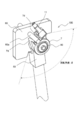
- FIG. 1 is a view showing an example of attachment of a side stand position detection device 100 and side stands 50 and 51 as members to be detected according to an embodiment of the present invention.
- FIG. 2 is a view showing an example of a structure for attaching the side stand position detecting device 100 and the side stand according to the embodiment of the present invention.
- FIG. 3 is a view for explaining a side stand position detecting device and a side stand mounting structure according to the embodiment of the present invention.
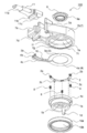
- FIG. 4 is an exploded perspective view of the position detection device 100 for the side stand according to the embodiment of the present invention as seen from the housing side.
- FIG. 1 is a view showing an example of attachment of a side stand position detection device 100 and side stands 50 and 51 as members to be detected according to an embodiment of the present invention.
- FIG. 2 is a view showing an example of a structure for attaching the side stand position detecting device 100 and the side stand according to the embodiment of the present invention.
- FIG. 3 is a view for explaining a side stand position detecting device
- FIG. 5 is an exploded perspective view of the position detection device 100 for the side stand according to the embodiment of the present invention as viewed from the rotating member side.
- FIG. 6 is a component diagram for explaining the formation state of the housing and the first and second fixed contact bodies.
- FIG. 7 is a diagram illustrating an assembled state of the rotating member and the movable contact body.
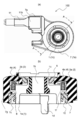
- FIG. 8 is an assembly view of the position detection device 100 for the side stand according to the embodiment of the present invention
- FIG. 8 (a) is a plan view of the appearance
- FIG. 8 (b) is an A- view shown in FIG. 8 (a). It is sectional drawing which shows A cross section.
- FIG. 9 is a diagram illustrating the relationship between the central angles of the movable contact body and the first and second fixed contact bodies.
- FIG. 9 is a diagram illustrating the relationship between the central angles of the movable contact body and the first and second fixed contact bodies.
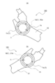
- FIG. 10 is a diagram for explaining the operation of the position detection device 100 for the side stand according to the embodiment of the present invention, and shows the positional relationship between the movable contact body and the first and second fixed contact bodies when attached to the left side of the vehicle.
- FIG. FIG. 11 is a diagram for explaining the operation of the position detection device 100 for the side stand according to the embodiment of the present invention, and shows the positional relationship between the movable contact body and the first and second fixed contact bodies when attached to the right side of the vehicle.
- FIG. FIG. 12 is a diagram for explaining the attachment position of the side stand with respect to the position detection device 100 for the side stand according to the embodiment of the present invention.
- the position detection device 100 for a side stand according to the present embodiment is attached together with the side stand 50 or 51 below the side of the vehicle body of the two-wheeled vehicle as shown in FIG. Fig.1 (a) has shown the example attached to the left side with respect to the advancing direction of the vehicle which is a 1st attachment state.
- FIG.1 (b) has shown the example attached to the right side of the vehicle which is a 2nd attachment state.
- FIG. 2 shows an example of an attachment structure for attaching to the left side of the vehicle shown in FIG.
- the side stand position detection device 100 is attached to a plate-like bracket 60 together with a side stand 50 that is a member to be detected.
- the side stand 50 is attached to the bracket 60 so as to be rotatable between a rotation angle ⁇ from a standing position to a storage position with a fixing bolt 70 as a support shaft.
- FIG. 3 is a diagram for explaining an example of the mounting structure shown in FIG.
- the position detection device 100 for the side stand rotates the rotating member 1 so that the engaging portion 1d of the rotating member 1 comes to a position corresponding to the first instruction portion 7h.
- the engaging portion 1 d engages with the engaging hole 50 a provided in the side stand 50, and is attached to the female screw hole 70 b provided in the head 70 a of the fixing bolt 70 with the attaching bolt 80.
- the casing 7 of the position detection device 100 for the side stand is fixed relative to the vehicle body regardless of the rotation of the side stand 50.
- the housing 7 is attached to the bracket 60 by inserting the shaft 60 a protruding from the bracket 60 into and engaging with the flange portion 7 d provided on the housing 7. Rotation is restricted.
- the rotating member 1 rotates around the mounting bolt 80 (fixed bolt 70) as the rotation axis, along with the rotation of the side stand 50 that is a non-detecting member.
- the side stand position detection device 100 includes a rotating member 1, a movable contact body 2, a first fixed contact body 3, a second fixed contact body 4, a housing 7, Consists of.
- an elastic member 8, a first protection member 9, a second protection member 10, and a connection member 11 are provided.
- the housing 7 is made of an insulating synthetic resin, and as shown in FIGS. 4 and 5, a housing portion 7c composed of a bottom portion 7a and a substantially cylindrical side wall portion 7b, and outside the housing portion 7c. It has the provided flange part 7d and the connection holding part 7e.
- the bottom 7a of the housing 7 is provided with a housing opening 7f into which the first protective member 9 and the mounting bolt 80 are inserted.
- first indicator 7h indicating the reference position of the rotating member 1 and the right side of the vehicle when attached to the left side of the vehicle.
- second indicating portion 7 i that indicates the reference position of the rotating member 1 when attached to the rotating member 1 is provided.
- the first fixed contact body 3 is formed using a conductive member such as a metal, and as shown in FIGS. 4 and 5, the plate-shaped and arc-shaped first fixed contact 3a, the first terminal portion 3b, It has the 1st connection part 3c connected.
- the second fixed contact body 4 is formed using a conductive member such as a metal, and as shown in FIGS. 4 and 5, has an arc shape having a plate shape and substantially the same diameter as the first fixed contact 3 a of the first fixed contact body 3.
- the movable contact body 2 is formed by using a conductive member such as a metal, and as shown in FIGS. 4 and 5, the movable contact body 2 has an arc shape substantially the same diameter as the first fixed contact 3a and the second fixed contact 4a. It has 1 sliding part 2a and 2nd sliding part 2b in the other end part. Further, a protrusion 2c is provided between the first and second sliding portions (2a, 2b) on a surface facing the surface on which the sliding portion is provided.
- the elastic member 8 is made of a material such as metal or synthetic resin, and uses a helical spring formed in a spiral shape as shown in FIGS.
- the rotating member 1 includes a base 1a having a cylindrical shape, a shaft 1c that protrudes in a cylindrical shape from the base 1a and has an opening 1b, and a direction opposite to the shaft 1c from the base 1a. 1d and the outer peripheral part 1e formed along the outer periphery of the base part 1a.
- the base portion 1a, the shaft portion 1c and the engaging portion 1d of the rotating member 1 are integrally formed of a metal member, and the outer peripheral portion 1e is formed of a synthetic resin material and integrally formed along the outer periphery of the base portion 1a.
- the outer peripheral portion 1 e has a projecting portion 2 c provided on the movable contact body 2 and a holding portion 1 f that holds the elastic member 8.
- the first protective member 9 is formed of a synthetic resin, and as shown in FIGS. 4 and 5, a first outer periphery formed in a cylindrical shape so as to be housed in a housing opening 7 f provided in the housing 7.
- the first insertion portion 9b through which the portion 9a and the shaft portion 1c of the rotating member 1 can be inserted is provided.
- the second protective member 10 is made of synthetic resin, and as shown in FIGS. 4 and 5, a second outer peripheral portion 10 a that is cylindrical and can be accommodated inside a side wall portion 7 b provided on the housing 7.
- the base portion 1a of the rotating member 1 has a second insertion portion 10b that can be inserted.
- connection member 11 includes a wiring member 11 a, a held portion 11 b for engaging the wiring member 11 a with the connection holding portion 7 e of the housing 7, and the first fixed contact body 3.
- the first terminal part 3b and the second terminal part 4b of the second fixed contact body 4 are connected.
- the first terminal portion 3 b of the first fixed contact body 3 and the second terminal portion 4 b of the second fixed contact body 4 are inside the connection holding portion 7 e of the housing 7.
- the connecting member 11 is disposed so as to be connectable to the connecting portion 11c.
- the housing 7 is formed with the first fixed contact body 3 and the second fixed contact body 4 integrally, and is fixed to the inner surface of the bottom portion 7a on the same circumference.
- the contact 3a and the second fixed contact 4a are exposed.
- a first gap 5 and a second gap 6 are provided between the first fixed contact 3a and the second fixed contact 4a.
- the movable contact body 2 is biased toward the first fixed contact body 3 and the second fixed contact body 4 when assembled on the holding portion 1f of the rotating member 1 (see FIG. 8B).
- the elastic member 8 for holding) is held.
- the holding portion 1 f holds the protrusion 2 c of the movable contact body 2, and the movable contact body 2 is configured to rotate as the rotating member 1 rotates.
- connection member 11 The to-be-held part 11b of the connection member 11 is engaged with the connection holding part 7e of the housing
- the connection portion 11c is connected to the first terminal portion 3b of the first fixed contact body 3 and the second terminal portion 4b of the second fixed contact body 4, and is connected to a control device or alarm device (not shown) via the wiring member 11a. Is done.
- the movable contact body 2 holds the first fixed contact body 3 and the second fixed contact in the storage portion 7 c of the housing 7 while holding the movable contact body 2 and the elastic member 8.
- the rotating member 1 is accommodated in a direction facing the contact body 4, and the caulking portion 7g is deformed and held rotatably.
- the first protective member 9 has a first outer peripheral portion 9a inserted into a housing opening 7f provided in the housing 7 so that foreign matter or the like does not enter the housing 7 from the bottom 7a side.
- the shaft portion 1c is held in a state of being inserted through the first insertion portion 9b and is fixed to the housing opening 7f of the housing 7.
- the second protective member 10 has a second outer peripheral portion 10a inserted into the side wall portion 7b of the housing 7 so that foreign matter or the like does not enter from the housing portion 7c side of the housing 7, and the base portion 1a of the rotating member 1 is It is held in a state of being inserted through the second insertion portion 10 b and is fixed to the side wall portion 7 b of the housing 7.
- the central angle ⁇ (°) of the first fixed contact 3a of the first fixed contact body 3 shown in FIG. Is set to be larger than the rotation angle ⁇ (°) of the side stand 50 or 51.
- the central angle ⁇ (°) between the first sliding portion 2 a and the second sliding portion 2 b of the movable contact body 2 is the first gap with respect to the rotation angle ⁇ (°) of the side stand 50 or 51.
- the central angle ⁇ 1 (°) of 5 or the central angle ⁇ 2 (°) of the second gap 6 is set to be larger than the larger one.
- the center angle ⁇ (°) of the second fixed contact 4 a of the second fixed contact body 4 is larger than the angle obtained by adding the center angle ⁇ (°) of the movable contact body 2 and the rotation angle ⁇ (°) of the side stand 50. Is set to
- the sum of the central angle ⁇ 1 (°) and the central angle ⁇ 2 (°) of the second gap 6 is 360 (°).
- FIG. 10 is a diagram illustrating an operation when the side stand 50 and the side stand position detection device 100, which are detected members, are attached to the left side of the vehicle
- FIG. 11 illustrates the side stand 51 and the side stand position detection device 100 to the right side of the vehicle. It is a figure which shows the operation
- movement at the time of attaching to. 10 and 11 are perspective views of the position detection device 100 for the side stand as seen from the bottom side of the housing 7 along the rotation axis of the rotating member 1, and the first stationary contact 3 a of the first stationary contact body 3.
- FIG. 10A shows that the side stand 50 is in the middle of the standing position and the stowed position, and is located at the reference position of the rotating member 1 when the side stand 50 as the detected member is attached to the left side of the vehicle. Indicates the state.
- FIG. 10B shows a state of the side stand position detection device 100 in a state where the side stand 50 is in the standing position
- FIG. 10C shows a state in which the side stand 50 is in the storage position.
- the side stand 50 and the side stand position detecting device 100 are attached to the left side of the vehicle, as shown in FIG. 10A, the side stand 50 is moved to the left side of the vehicle at a position halfway between the standing position and the storage position. At the time of attachment, attachment is performed in accordance with the position to be the reference position of the rotating member 1.
- the first sliding portion 2a of the movable contact body 2 is in a position corresponding to the first gap 5, and the second sliding portion 2b is second. It arrange
- the rotating member 1 When the side stand 50 rotates clockwise from the reference position where the side stand 50 is attached to the left side of the vehicle shown in FIG. 10A and reaches the standing position, the rotating member 1 also rotates clockwise as the side stand 50 rotates. . As the rotating member 1 rotates, the movable contact body 2 also rotates, and the first sliding portion 2a and the second sliding portion 2b are both fixed to the second fixed contact body 4 as shown in FIG. It will be in the state which has contacted the contact 4a. Therefore, the first fixed contact body 3 and the second fixed contact body 4 are in a non-conductive state.
- the rotating member 1 also rotates counterclockwise as the side stand 50 rotates.
- the movable contact body 2 also rotates.
- the first sliding portion 2a contacts the first fixed contact 3a of the first fixed contact body 3, and the second The sliding portion 2b is in contact with the second fixed contact 4a of the second fixed contact body 4. For this reason, between the 1st fixed contact body 3 and the 2nd fixed contact body 4 will be in a conduction state.
- the position between the first fixed contact body 3 and the second fixed contact body 4 is determined between the standing position and the storage position of the side stand 50.
- a non-conduction state and a conduction state can be switched.
- the position detecting operation of the side stand 50 which is a member to be detected can be performed.
- FIG. 11 (a) shows that the side stand 51 is in the middle of the standing position and the storage position, and when the side stand 51, which is a detected member, is attached to the right side of the vehicle, the side stand 51 is at a position that becomes the reference position of the rotating member 1. It shows a certain state.
- FIG. 11B shows the state of the side stand position detection device 100 in a state where the side stand 51 is in the standing position
- FIG. 11C shows a state in which the side stand 51 is in the storage position.
- the side stand 51 and the side stand position detecting device 100 are attached to the right side of the vehicle, as shown in FIG. 11A, the side stand 51 is moved to the left side of the vehicle at a position halfway between the standing position and the storage position. At the time of attachment, attachment is performed in accordance with the position to be the reference position of the rotating member 1.
- the engaging portion 1d of the rotating member 1 comes to a position corresponding to the second instruction portion 7i.
- the rotating member 1 is rotated, and the engaging portion 1d of the rotating member 1 and the side stand 51 are provided at the position of the second indicating portion 7i indicating the position where the engaging portion 1d of the rotating member 1 is located. It is attached so that the holes 51a are engaged.
- the rotating member 1 When the side stand 51 rotates clockwise from the reference position where the side stand 51 is attached to the right side of the vehicle shown in FIG. 11A and reaches the storage state, the rotating member 1 also rotates clockwise as the side stand 51 rotates. . As the rotating member 1 rotates, the movable contact body 2 also rotates. As shown in FIG. 11C, the first sliding portion 2a contacts the first fixed contact 3a of the first fixed contact body 3, and the second The sliding portion 2b is in contact with the second fixed contact 4a of the second fixed contact body 4. For this reason, the first fixed contact body 3 and the second fixed contact body 4 are in a conductive state.
- the rotating member 1 when the side stand 51 rotates counterclockwise and reaches the standing position, the rotating member 1 also rotates counterclockwise as the side stand 51 rotates.
- the movable contact body 2 As the rotating member 1 rotates, the movable contact body 2 also rotates, and the first sliding portion 2a and the second sliding portion 2b are both fixed to the second fixed contact body 4 as shown in FIG. It will be in the state which has contacted the contact 4a. Therefore, the first fixed contact body 3 and the second fixed contact body 4 are in a non-conductive state.
- the first fixed contact body 3 and the second fixed contact body 4 can be It is possible to switch between a non-conductive state and a conductive state. For this reason, the position detecting operation of the side stand 51 which is a member to be detected can be performed.
- the first fixed contact body 3 and the second fixed contact body 4 are non-conductive in the standing position, and the storage position Thus, the first fixed contact body 3 and the second fixed contact body 4 are in a conductive state. Therefore, attachment to either the left or right side can be handled without changing the processing of the alarm device or the control device using the position detection device 100 of the side stand.
- the movable contact body 2 is moved to the first sliding position when viewed from one direction along the rotation axis of the rotating member 1 in the first (left side of the vehicle) attachment state.
- the second sliding portion 2b is arranged at a position corresponding to the first gap 5 and the second sliding portion 2b is in contact with the second fixed contact body 4, and the movable contact is in the second (right side of the vehicle) attachment state.
- the body 2 is configured such that the first sliding portion 2 a is disposed at a position where the first sliding portion 2 a is in contact with the second fixed contact body 4, and the second sliding portion 2 b is disposed at a position corresponding to the second gap 6.
- first sliding portion 2a and the second sliding portion 2b are second fixed at a rotation completion position (stand-up position) in one rotation direction (clockwise) from the first (left side of the vehicle) attachment state.
- the first sliding portion 2a is in contact with the first fixed contact body 3 and the second sliding portion at a rotation completion position (storage position) in another rotation direction (counterclockwise) in contact with the contact body 4.
- Reference numeral 2b is in contact with the second fixed contact body 4, and the first sliding portion 2a is in the rotation completion position (storage position) in the one rotation direction (clockwise) from the second (right side of the vehicle) attachment state.
- first sliding portion 2a and the second sliding portion 2b are configured to be in contact with the second fixed contact body 4.
- the movable contact body 2 rotates with the rotation of the side stand that is the member to be detected, so that the space between the first fixed contact body 3 and the second fixed contact body 4 Since conduction and non-conduction can be switched, the position of the side stand can be detected.
- the casing 7 is configured to be provided with a first instruction portion 7h indicating a first attachment state and a second instruction portion 7i indicating a second attachment state with respect to the rotating member 1. .
- the movable contact body is obtained by setting the engaging portion 1d of the rotating member 1 to the position corresponding to the first indicating portion 7h or the second indicating portion 7i in accordance with the mounting state of the position detection device 100 of the side stand.
- the position of 2 can be easily adjusted.
- the side stand position detection device 100 of the present embodiment it is possible to provide a side stand position detection device that can be attached to either side of the vehicle body with a simple configuration.
- the side stand position detection device according to the embodiment of the present invention has been specifically described.
- the present invention is not limited to the above-described embodiment, and various modifications can be made without departing from the scope of the invention. It is possible to implement.
- the present invention can be modified as follows, and these embodiments also belong to the technical scope of the present invention.
- the first fixed contact 3a of the first fixed contact body 3 and the second fixed contact 4a of the second fixed contact body 4 have been described as having an annular structure, but are arranged in a cylindrical shape. May be configured.
- the first fixed contact body 3 and the second fixed contact body 4 are in a non-conductive state at the standing position, and between the first fixed contact body 3 and the second fixed contact body 4 at the storage position.
- the description has been made with reference to an example in which is in a conductive state, it may be configured to be in a conductive state at an upright position and a non-conductive state at a storage position.
- the widths of the first gap 5 and the second gap 6 are not particularly described, but the widths of the first gap 5 and the second gap 6 It is also possible to provide an insensitive area by setting the gap larger than the width in the sliding direction of the first sliding part 2a and the second sliding part 2b. In addition, by setting the width of the first gap 5 and the second gap 6 to be smaller than the width of the first sliding portion 2a and the second sliding portion 2b of the movable contact body 2, the insensitive area is eliminated. It is also possible to configure.
Landscapes
- Engineering & Computer Science (AREA)
- Mechanical Engineering (AREA)
- Rotary Switch, Piano Key Switch, And Lever Switch (AREA)
- A Measuring Device Byusing Mechanical Method (AREA)
Abstract
【課題】簡易な構成で車体のどちら側へも取り付けることができるサイドスタンドの位置検出装置を提供する。 【解決手段】被検知部材であるサイドスタンドの回転とともに回転可能な回転部材1と、一端部に第1摺動部2aを有し、他端部に第2摺動部2bを有し、回転部材1の回転とともに回転動作する可動接点体2と、可動接点体2の第1摺動部2a及び第2摺動部2bが摺動され、第1の隙間と第2の隙間を設けて同一円周上に配置された第1固定接点体3と第2固定接点体4と、を備え、回転部材1の回転軸に沿った一の方向から見て、第1の取り付け状態のとき可動接点体2は、第1摺動部2aが第1の隙間5に対応する位置で、第2摺動部2bは第2固定接点体4に接する位置となるよう配置され、第2の取り付け状態のとき可動接点体2は、第1摺動部2aが前記第2固定接点体に接する位置で、第2摺動部2bは第2の隙間6に対応する位置となるよう配置される。
Description
本発明は、位置検出装置に関し、特に、自動二輪車等の二輪車を支持するサイドスタンドの位置を検出するサイドスタンドの位置検出装置に関する。
一般に、自動二輪車等の二輪車には、駐車する際に車体を起立状態に支持するサイドスタンドが設けられている。このようなサイドスタンドは、起立位置では二輪車を起立状態で支持するとともに、格納位置では地面と接触しない姿勢で格納されるようになっている。
サイドスタンドが起立位置の状態で二輪車が走行してしまうと、サイドスタンドが走行の妨げとなるので、サイドスタンドが起立位置にある状態のまま走行するのを回避するため、サイドスタンドが起立位置にあることを警告することや、エンジンが始動しないように制御すること等が行なわれている。そのような制御を行なうため、従来から、サイドスタンドの位置を検出する位置検出装置が提案されている。
従来のサイドスタンドの位置検出装置としては、下記の特許文献1に記載のサイドスタンドの位置検出装置が知られている。以下、特許文献1に記載のサイドスタンドの位置検出装置について図13及び図14を用いて説明する。
特許文献1に記載のサイドスタンドの位置検出装置900は、図13に示すように、ハウジング901の他、サイドスタンドに固定されるとともにハウジング901に回動可能に支持されるロータ902と、ロータ902に固定される可動接点903とハウジング901に固定される固定接点904とを有してハウジング901内に設けられる接点構造と、を備えている。
図14に示すように、固定接点904は、間隙905によって延設方向に少なくとも二つの帯状端子904a,904bに分割されており、ロータ902に固定される可動接点903が、ロータ902の回動角度、すなわちサイドスタンドの回動角度に応じてこれら二つの帯状端子904a,904bを導通(短絡)させるか否かによって、当該回動角度を検出できるようになっている。
サイドスタンドを二輪車両へ取り付ける場合に、車体の進行方向に対して左側へ取り付ける場合と右側へ取り付ける場合とがあり、サイドスタンドの位置検出装置もサイドスタンドが取り付けられる向きに合わせて取り付ける必要がある。
しかしながら、上述した従来技術のサイドスタンドの位置検出装置ではこのことが考慮されていないため、進行方向に対して左側へ取り付ける場合と右側へ取り付ける場合の、それぞれに対応した位置検出装置を用意する必要があるという課題があった。
本発明は、上述した課題を解決するもので、簡易な構成で車体のどちら側へも取り付けることができるサイドスタンドの位置検出装置を提供することを目的とする。
この課題を解決するために、本発明のサイドスタンドの位置検出装置は、被検知部材の回転とともに回転可能な回転部材と、一端部に第1摺動部を有し、他端部に第2摺動部を有し、前記回転部材の回転とともに回転動作する可動接点体と、前記可動接点体の前記第1摺動部及び前記第2摺動部が摺動され、第1の隙間と第2の隙間を設けて同一円周上に配置された第1固定接点体と第2固定接点体と、を備え、前記回転部材の回転軸に沿った方向から見て、第1の取り付け状態のとき、前記可動接点体は、前記第1摺動部が前記第1の隙間に対応する位置で、前記第2摺動部は前記第2固定接点体に接する位置となるよう配置され、第2の取り付け状態のとき、前記可動接点体は、前記第1摺動部が前記第2固定接点体に接する位置で、前記第2摺動部は前記第2の隙間に対応する位置となるよう配置され、前記第1の取り付け状態から、一の回転方向への回転完了位置において、前記第1摺動部及び前記第2摺動部は前記第2固定接点体に接しており、他の回転方向への回転完了位置において、前記第1摺動部は前記第1固定接点体に接するとともに、前記第2摺動部は前記第2固定接点体に接しており、前記第2の取り付け状態から、一の回転方向への回転完了位置において、前記第1摺動部は前記第1固定接点体に接するとともに、前記第2摺動部は前記第2固定接点体に接しており、他の回転方向への回転完了位置において、前記第1摺動部及び前記第2摺動部は前記第2固定接点体に接していることを特徴とする。
これによれば、本発明のサイドスタンドの位置検出装置は、回転部材の回転軸に沿った一の方向から見て、第1の取り付け状態である車両の左側に取り付けた場合、可動接点体を、第1摺動部が第1の隙間に対応する位置で、第2摺動部は第2固定接点体に接する位置となるよう配置される。この取り付け位置から一の回転方向への回転完了位置となるサイドスタンドの起立位置において、第1摺動部及び第2摺動部は第2固定接点体に接しており、いるため、第1固定接点と第2固定接点の間は非導通となる。他の回転方向への回転完了位置となる収納位置において、第1摺動部は第1固定接点体に接するとともに、第2摺動部は前記第2固定接点体に接しているため、第1固定接点と第2固定接点の間が導通するようになる。また、第2の取り付け状態である車両の右側に取り付けた場合、可動接点体は、第1摺動部が第2固定接点体に接する位置で、第2摺動部は第2の隙間に対応する位置となるよう配置される。この取り付け位置から一の回転方向への回転完了位置となる収納位置において、第1摺動部は第1固定接点体に接するとともに、第2摺動部は第2固定接点体に接しているため、第1固定接点と第2固定接点の間が導通するようになる。他の回転方向への回転完了位置となる起立位置において、第1摺動部及び第2摺動部は第2固定接点体に接しているため、第1固定接点と第2固定接点の間は非導通となる。このため、第1の取り付け状態である車両の左側に取り付けた場合、または第2の取り付け状態である車両の右側に取り付けた場合、のどちらの場合でも、可動接点体の回転にともなって、第1固定接点体と第2固定接点体との間の導通と非導通とを切換えることができる。従って、簡易な構成で車体のどちら側へも取り付けることができるサイドスタンドの位置検出装置を提供することができる。
また、本発明のサイドスタンドの位置検出装置は、前記可動接点体と、前記第1固定接点体と、前記第2固定接点体が収納される筐体を有し、前記筐体には、前記回転部材に対して、前記第1の取り付け状態を示す第1の指示部と、前記第2の取り付け状態を示す第2の指示部とが設けられていることを特徴とする。
これによれば、筐体には、回転部材に対して、第1の取り付け状態を示す第1の指示部と、第2の取り付け状態を示す第2の指示部とが設けられている。このため、回転部材をサイドスタンドの位置検出装置の取り付け状態に合わせて、第1の指示部または第2の指示部に合わせた位置とすることで、可動接点体の位置を容易に合わせることができる。
また、本発明のサイドスタントの位置検出装置は、被検知部材の回転角度をθとしたとき、前記第1固定接点体の第1固定接点の中心角αは、被検知部材の回転角度θより大きくなるように設定され、前記可動接点体の第1摺動部と第2摺動部との中心角γは、被検知部材の回転角度θに対して、前記第1の隙間の中心角δ1または前記第2の隙間の中心角δ2の何れか大きい方を加えた角度より大きくなるように設定され、前記第2固定接点体の第2固定接点の中心角βは、前記可動接点体の中心角γと被検知部材の回転角度θを加えた角度より大きくなるように設定され、前記第1固定接点体の第1固定接点の中心角αと、前記第2固定接点体の第2固定接点の中心角βと、第1の隙間の中心角δ1と、第2の隙間の中心角δ2との合計角度は360(°)となっていることを特徴とする。
これによれば、被検知部材の回転角度θに対して、可動接点体、第1固定接点体及び第2固定接点体のそれぞれの角度を設定している。これにより、車体のどちら側に取り付けても、可動接点体の回転にともなって、第1固定接点体と第2固定接点体との間の導通と非導通とを切換えることが可能な設定とすることができる。
また、本発明のサイドスタントの位置検出装置は、被検知部材の回転角度をθとしたとき、前記第1固定接点体の第1固定接点の中心角αは、被検知部材の回転角度θより大きくなるように設定され、前記可動接点体の第1摺動部と第2摺動部との中心角γは、被検知部材の回転角度θに対して、前記第1の隙間の中心角δ1または前記第2の隙間の中心角δ2の何れか大きい方を加えた角度より大きくなるように設定され、前記第2固定接点体の第2固定接点の中心角βは、前記可動接点体の中心角γと被検知部材の回転角度θを加えた角度より大きくなるように設定され、前記第1固定接点体の第1固定接点の中心角αと、前記第2固定接点体の第2固定接点の中心角βと、第1の隙間の中心角δ1と、第2の隙間の中心角δ2との合計角度は360(°)となっていることを特徴とする。
これによれば、被検知部材の回転角度θに対して、可動接点体、第1固定接点体及び第2固定接点体のそれぞれの角度を設定している。これにより、車体のどちら側に取り付けても、可動接点体の回転にともなって、第1固定接点体と第2固定接点体との間の導通と非導通とを切換えることが可能な設定とすることができる。
本発明のサイドスタンドの位置検出装置は、回転部材の回転軸に沿った一の方向から見て、第1の取り付け状態のとき可動接点体を、第1摺動部が第1の隙間に対応する位置で、第2摺動部は第2固定接点体に接する位置となるよう配置され、第2の取り付け状態のとき可動接点体は、第1摺動部が第2固定接点体に接する位置で、第2摺動部は第2の隙間に対応する位置となるよう配置されるように構成した。また、第1の取り付け状態から、一の回転方向への回転完了位置において、第1摺動部及び第2摺動部は第2固定接点体に接しており、他の回転方向への回転完了位置において、第1摺動部は第1固定接点体に接するとともに、第2摺動部は前記第2固定接点体に接しており、第2の取り付け状態から、一の回転方向への回転完了位置において、第1摺動部は第1固定接点体に接するとともに、第2摺動部は第2固定接点体に接しており、他の回転方向への回転完了位置において、第1摺動部及び第2摺動部は第2固定接点体に接しているように構成した。このため、車両のどちら側に取り付けても、可動接点体の回転にともなって、第1固定接点と第2固定接点との間の導通と非導通とを切換えることができるので、簡易な構成で車体のどちら側へも取り付けることができるサイドスタンドの位置検出装置を提供することができる。
[実施形態]
以下に本発明の実施形態におけるサイドスタンドの位置検出装置100について図1から図12を用いて説明する。図1は、本発明の実施形態に係るサイドスタンドの位置検出装置100と被検知部材であるサイドスタンド50、51の取り付け例を示す図である。図2は、本発明の実施形態に係るサイドスタンドの位置検出装置100とサイドスタンドの取り付け構造例を示す図である。図3は、本発明の実施形態に係るサイドスタンドの位置検出装置とサイドスタンドの取り付け構造を説明する図である。図4は、本発明の実施形態に係るサイドスタンドの位置検出装置100を筐体側から見た分解斜視図である。図5は、本発明の実施形態に係るサイドスタンドの位置検出装置100を回転部材側から見た分解斜視図である。図6は、筐体と第1及び第2固定接点体の形成状態を説明する部品図である。図7は、回転部材と可動接点体の組立て状態を示す図である。図8は本発明の実施形態に係るサイドスタンドの位置検出装置100の組立て図で、図8(a)は外観の平面図であり、図8(b)は、図8(a)に示すA‐A断面を示す断面図である。図9は、可動接点体と第1及び第2固定接点体の中心角の関係を示す図である。図10は、本発明の実施形態に係るサイドスタンドの位置検出装置100の動作を説明する図で、車両の左側に取り付けられた場合の可動接点体と第1及び第2固定接点体の位置関係を示す図である。図11は、本発明の実施形態に係るサイドスタンドの位置検出装置100の動作を説明する図で、車両の右側に取り付けられた場合の可動接点体と第1及び第2固定接点体の位置関係を示す図である。図12は、本発明の実施形態に係るサイドスタンドの位置検出装置100に対するサイドスタンドの取り付け位置を説明する図である。
以下に本発明の実施形態におけるサイドスタンドの位置検出装置100について図1から図12を用いて説明する。図1は、本発明の実施形態に係るサイドスタンドの位置検出装置100と被検知部材であるサイドスタンド50、51の取り付け例を示す図である。図2は、本発明の実施形態に係るサイドスタンドの位置検出装置100とサイドスタンドの取り付け構造例を示す図である。図3は、本発明の実施形態に係るサイドスタンドの位置検出装置とサイドスタンドの取り付け構造を説明する図である。図4は、本発明の実施形態に係るサイドスタンドの位置検出装置100を筐体側から見た分解斜視図である。図5は、本発明の実施形態に係るサイドスタンドの位置検出装置100を回転部材側から見た分解斜視図である。図6は、筐体と第1及び第2固定接点体の形成状態を説明する部品図である。図7は、回転部材と可動接点体の組立て状態を示す図である。図8は本発明の実施形態に係るサイドスタンドの位置検出装置100の組立て図で、図8(a)は外観の平面図であり、図8(b)は、図8(a)に示すA‐A断面を示す断面図である。図9は、可動接点体と第1及び第2固定接点体の中心角の関係を示す図である。図10は、本発明の実施形態に係るサイドスタンドの位置検出装置100の動作を説明する図で、車両の左側に取り付けられた場合の可動接点体と第1及び第2固定接点体の位置関係を示す図である。図11は、本発明の実施形態に係るサイドスタンドの位置検出装置100の動作を説明する図で、車両の右側に取り付けられた場合の可動接点体と第1及び第2固定接点体の位置関係を示す図である。図12は、本発明の実施形態に係るサイドスタンドの位置検出装置100に対するサイドスタンドの取り付け位置を説明する図である。
本実施形態に係るサイドスタンドの位置検出装置100は、図1に示すように、二輪車量の車体側部の下方にサイドスタンド50または51とともに取り付けられる。図1(a)は、第1の取り付け状態である車両の進行方向に対して左側に取り付けられた例を示している。図1(b)は、第2の取り付け状態である車両の右側に取り付けられた例を示している。
図2は、図1(a)に示す、車両の左側に取り付ける場合の取り付け構造例を示している。本実施形態に係るサイドスタンドの位置検出装置100は、被検知部材であるサイドスタンド50とともに板状のブラケット60に取り付けられる。図2に示すように、サイドスタンド50はブラケット60に対して、固定ボルト70を支軸として、起立位置から収納位置までの回転角度θの間を回転可能となるように取り付けられる。
図3は、図2に示す取り付け構造例を説明する図である。図3に示すように、サイドスタンドの位置検出装置100は、第1の指示部7hに対応する位置に、回転部材1の係合部1dがくるように、回転部材1を回転させ、回転部材1の係合部1dがサイドスタンド50に設けられた係合用穴50aと係合するとともに、固定ボルト70の頭部70aに設けられた雌ネジ孔70bに取り付け用ボルト80で取り付けられる。
また、サイドスタンドの位置検出装置100の筐体7は、サイドスタンド50の回転に拘わらず車体に対して相対的に固定される。図2及び図3に示すように、筐体7に設けられたフランジ部7dに、ブラケット60から突設されるシャフト60aを挿通して係合することで、筐体7がブラケット60に対して回転することが規制される。このように取り付けることで、回転部材1は、非検知部材であるサイドスタンド50の回転とともに、取り付け用ボルト80(固定ボルト70)を回転軸として回転する。
次に、サイドスタンドの位置検出装置100の構成について、図4から図6を用いて説明する。
サイドスタンドの位置検出装置100は、図4及び図5に示すように、回転部材1と、可動接点体2と、第1固定接点体3と、第2固定接点体4と、筐体7と、で構成される。その他に、弾性部材8と第1防護部材9と、第2防護部材10と、接続部材11と、を備えている。
筐体7は、絶縁性の合成樹脂で形成され、図4及び図5に示すように、底部7aと略円筒形状の側壁部7bとで構成される収納部7cと、収納部7cの外側に設けられたフランジ部7dと、接続保持部7eと、を有している。また筐体7の底部7aには、第1防護部材9と取り付け用ボルト80が挿入される筐体開口部7fが設けられている。
図6(a)に示すように、筐体7の底部7aの外側には、車両の左側への取り付けの際に、回転部材1の基準位置を示す第1の指示部7h及び、車両の右側への取り付けの際に回転部材1の基準位置を示す第2の指示部7iが設けられている。
第1固定接点体3は金属等の導電性部材を用いて形成され、図4及び図5に示すように、板状かつ弧状の第1固定接点3aと、第1端子部3bと、それらを接続している第1接続部3cとを有している。
第2固定接点体4は金属等の導電性部材を用いて形成され、図4及び図5に示すように、板状かつ第1固定接点体3の第1固定接点3aと略同径の弧状の第2固定接点4aと、第2端子部4bと、それらを接続している第2接続部4cとを有している。
可動接点体2は金属等の導電性部材を用いて形成され、図4及び図5に示すように、第1固定接点3a及び第2固定接点4aと略同径の弧状で、一端部に第1摺動部2aと、他端部に第2摺動部2bと、を有している。また、第1及び第2の摺動部(2a、2b)の間には、摺動部が設けられている面と対向する面に、突起部2cが設けられている。
弾性部材8は、金属や合成樹脂などの材料で、図4及び図5に示すように、螺旋状に形成されたコイルバネが用いられる。
回転部材1は、図4及び図5に示すように、円筒形状を有する基部1aと基部1aから円筒形状に突出し開口部1bを有する軸部1cと、基部1aから軸部1cとは反対の方向に突出する係合部1dと、基部1aの外周に沿って形成される外周部1eを有している。回転部材1の基部1aと軸部1cと係合部1dは、金属製の部材で一体的に形成されており、外周部1eは合成樹脂材料で、基部1aの外周に沿って一体的に形成されている。また、外周部1eには、可動接点体2に設けられた突起部2c及び弾性部材8を保持する保持部1fを有している。
第1防護部材9は、合成樹脂で形成されており、図4及び図5に示すように、円筒形状で筐体7に設けられた筐体開口部7fに収納可能に形成された第1外周部9aと、回転部材1の軸部1cが挿通可能な第1挿通部9bを有している。
第2防護部材10は、合成樹脂で形成されており、図4及び図5に示すように、円筒形状で筐体7に設けられた側壁部7bの内側に収納可能な第2外周部10aと、回転部材1の基部1aが挿通可能な第2挿通部10bを有している。
接続部材11は、図4及び図5に示すように、配線部材11aと、配線部材11aを筐体7の接続保持部7eに係合するための被保持部11bと、第1固定接点体3の第1端子部3b及び第2固定接点体4の第2端子部4bと接続する接続部11cを有している。
次にサイドスタンドの位置検出装置100の構造について図6から図9を用いて説明する。
図6(a)に示すように、筐体7の接続保持部7eの内側には、第1固定接点体3の第1端子部3b及び、第2固定接点体4の第2端子部4bが、接続部材11の接続部11cと接続可能に配置されている。
図6(b)に示すように、筐体7には、第1固定接点体3と第2固定接点体4が一体的に成形され、底部7aの内面に同一円周上に、第1固定接点3a及び第2固定接点4aが露出している。また、第1固定接点3aと第2固定接点4aとの間には、第1の隙間5と第2の隙間6が設けられている。
回転部材1の保持部1fには図7に示すように、組み立てた際に、可動接点体2を第1固定接点体3及び第2の固定接点体4の側に付勢(図8(b)参照)するための弾性部材8が保持されている。また、保持部1fには可動接点体2の突起部2cが保持され、回転部材1の回転とともに可動接点体2も回転動作するよう構成されている。
接続部材11の被保持部11bは、図8(a)に示すように、筐体7の接続保持部7eに係合される。接続部11cは第1固定接点体3の第1端子部3b及び第2固定接点体4の第2端子部4bと接続され、配線部材11aを介して、図示しない制御装置あるいは警報装置などに接続される。
筐体7の収納部7cには、図8(b)に示すように、可動接点体2と弾性部材8とを保持した状態で、可動接点体2が第1固定接点体3及び第2固定接点体4と対向する向きに、回転部材1が収納され、カシメ部7gを変形させて回転可能に保持される。
第1防護部材9は、筐体7の内部に底部7a側から異物などが侵入しないように、筐体7に設けられた筐体開口部7fに第1外周部9aが挿入され、回転部材1の軸部1cが第1挿通部9bに挿通された状態で保持され、筐体7の筐体開口部7fに固定される。
第2防護部材10は、筐体7の収納部7c側から内部に異物等が侵入しないように、筐体7の側壁部7bに第2外周部10aが挿入され、回転部材1の基部1aが第2挿通部10bに挿通された状態で保持され、筐体7の側壁部7bに固定される。
次に、第1固定接点体3の第1固定接点3aと、第2固定接点体4の第2固定接点4aと、可動接点体2に設けられた第1摺動部2aと、他端部に第2摺動部2bとの関係について図9を用いて説明する。
被披検知部材であるサイドスタンド50または51の回転角度を図2に示すθ(°)としたときに、図9に示す第1固定接点体3の第1固定接点3aの中心角α(°)は、サイドスタンド50または51の回転角度θ(°)より大きくなるように設定されている。また、可動接点体2の第1摺動部2aと第2摺動部2bと、の中心角γ(°)は、サイドスタンド50または51の回転角度θ(°)に対して、第1の隙間5の中心角δ1(°)または第2の隙間6の中心角δ2(°)の何れか大きい方を加えた角度より大きくなるように設定されている。第2固定接点体4の第2固定接点4aの中心角β(°)は、可動接点体2の中心角γ(°)とサイドスタンド50の回転角度θ(°)を加えた角度より大きくなるように設定されている。
なお、第1固定接点体3の第1固定接点3aの中心角α(°)と、第2固定接点体4の第2固定接点4aの中心角β(°)と、第1の隙間5の中心角δ1(°)と、第2の隙間6の中心角δ2(°)の合計は360(°)である。
次に、サイドスタンドの位置検出装置100の動作について、図10から図12を用いて説明する。
図10は、被検知部材であるサイドスタンド50及びサイドスタンドの位置検出装置100を車両に左側に取り付けた際の動作を示す図であり、図11はサイドスタンド51及びサイドスタンドの位置検出装置100を車両に右側に取り付けた際の動作を示す図である。図10及び図11は、サイドスタンドの位置検出装置100を、回転部材1の回転軸に沿って筐体7の底部側から見た透視図で、第1固定接点体3の第1固定接点3aと、第2固定接点体4の第2固定接点4aと、可動接点体2の一端部に設けられた第1摺動部2aと、他端部に設けられた第2摺動部2bとの関係を示している。
まず、図10(a)はサイドスタンド50が起立位置と収納位置との途中で、被検知部材であるサイドスタンド50を車両の左側への取り付けの際に、回転部材1の基準位置となる位置にある状態を示している。また、図10(b)はサイドスタンド50が起立位置にある状態、図10(c)は収納位置にある状態、のサイドスタンドの位置検出装置100の状態を示している。
車両の左側にサイドスタンド50及びサイドスタンドの位置検出装置100を取り付ける場合、図10(a)に示すように、サイドスタンド50が起立位置と収納位置との途中の位置で、サイドスタンド50を車両の左側への取り付けの際に、回転部材1の基準位置となる位置に合わせて取り付けを行なう。
具体的には、図12(a)に示すように、回転部材1が左側取り付けの基準位置にあるとき、回転部材1の係合部1dが位置する場所を示す第1の指示部7hの位置で回転部材1の係合部1dとサイドスタンド50が係合するように取り付ける。
このように取り付けた場合、図10(a)に示すように、可動接点体2の第1摺動部2aは第1の隙間5に対応する位置にあり、第2摺動部2bは第2固定接点4aに接する位置となるよう配置される。
図10(a)に示す車両の左側にサイドスタンド50を取り付ける基準位置から、サイドスタンド50が時計回りに回転し起立位置に到達した場合、回転部材1もサイドスタンド50の回転にともなって時計方向へ回転する。回転部材1の回転とともに可動接点体2も回転動作し、図10(b)に示すように、第1摺動部2aと第2摺動部2bはともに第2固定接点体4の第2固定接点4aに接している状態となる。このため、第1固定接点体3と第2固定接点体4の間は非導通状態となる。
また反対に、サイドスタンド50が反時計周りに回転し収納位置に到達した場合、回転部材1もサイドスタンド50の回転にともなって反時計方向へ回転する。回転部材1の回転とともに可動接点体2も回転動作し、図10(c)に示すように、第1摺動部2aは第1固定接点体3の第1固定接点3aに接するとともに、第2摺動部2bは第2固定接点体4の第2固定接点4aに接している状態となる。このため、第1固定接点体3と第2固定接点体4の間は導通状態となる。
以上のように、車両の左側にサイドスタンド50及びサイドスタンドの位置検出装置100を取り付けた場合、サイドスタンド50の起立位置と収納位置とで、第1固定接点体3と第2固定接点体4の間の非導通状態と導通状態とを切り替えることができる。このため被検知部材であるサイドスタンド50の位置検出動作を行なうことができる。
次に、図11(a)はサイドスタンド51が起立位置と収納位置との途中で、被検知部材であるサイドスタンド51を車両の右側への取り付けの際に、回転部材1の基準位置となる位置にある状態を示している。また、図11(b)はサイドスタンド51が起立位置にある状態、図11(c)は収納位置にある状態、のサイドスタンドの位置検出装置100の状態を示している。
車両の右側にサイドスタンド51及びサイドスタンドの位置検出装置100を取り付ける場合、図11(a)に示すように、サイドスタンド51が起立位置と収納位置との途中の位置で、サイドスタンド51を車両の左側への取り付けの際に、回転部材1の基準位置となる位置に合わせて取り付けを行なう。
具体的には、図12(b)に示すように、回転部材1が右側取り付けの基準位置にあるとき、第2の指示部7iに対応する位置に、回転部材1の係合部1dがくるように、回転部材1を回転させ、回転部材1の係合部1dが位置する場所を示す第2の指示部7iの位置で回転部材1の係合部1dとサイドスタンド51に設けられた係合用穴51aが係合するように取り付ける。
このように取り付けた場合、図11(a)に示すように、可動接点体2の第1摺動部2aが第2固定接点体4の第2固定接点4aに接する位置で、第2摺動部2bは第2の隙間6に対応する位置となるよう配置される。
図11(a)に示す車両の右側にサイドスタンド51を取り付ける基準位置から、サイドスタンド51が時計回りに回転し収納状態に到達した場合、回転部材1もサイドスタンド51の回転にともなって時計方向へ回転する。回転部材1の回転とともに可動接点体2も回転動作し、図11(c)に示すように、第1摺動部2aは第1固定接点体3の第1固定接点3aに接するとともに、第2摺動部2bは第2固定接点体4の第2固定接点4aに接している状態となる。そのため第1固定接点体3と第2固定接点体4の間は導通状態となる。
また反対に、サイドスタンド51が反時計周りに回転し起立位置に到達した場合、回転部材1もサイドスタンド51の回転にともなって反時計周りに回転する。回転部材1の回転とともに可動接点体2も回転動作し、図11(b)に示すように、第1摺動部2aと第2摺動部2bはともに第2固定接点体4の第2固定接点4aに接している状態となる。そのため、第1固定接点体3と第2固定接点体4の間は非導通状態となる。
以上のように、車両の右側にサイドスタンド51及びサイドスタンドの位置検出装置100を取り付けた場合においても、サイドスタンド51の起立位置と収納位置とで、第1固定接点体3と第2固定接点体4の間の非導通状態と導通状態とを切り替えることができる。このため被検知部材であるサイドスタンド51の位置検出動作を行いことができる。
また、車両の左側に取り付けた場合と右側に取り付けた場合のどちらの場合であっても、起立位置で第1固定接点体3と第2固定接点体4の間は非導通であり、収納位置で第1固定接点体3と第2固定接点体4の間は導通状態となる。そのため、サイドスタンドの位置検出装置100を用いた警報装置や制御装置の処理に変更を行なうことなく左右どちら側への取り付けにも対応することができる。
以下、本実施形態としたことによる効果について説明する。
本実施形態のサイドスタンドの位置検出装置100では、回転部材1の回転軸に沿った一の方向から見て、第1(車両の左側)の取り付け状態のとき可動接点体2を、第1摺動部2aが第1の隙間5に対応する位置で、第2摺動部2bは第2固定接点体4に接する位置となるよう配置され、第2(車両の右側)の取り付け状態のとき可動接点体2は、第1摺動部2aが第2固定接点体4に接する位置で、第2摺動部2bは第2の隙間6に対応する位置となるよう配置されるように構成した。
また、第1(車両の左側)の取り付け状態から、一の回転方向(時計周り)への回転完了位置(起立位置)において、第1摺動部2a及び第2摺動部2bは第2固定接点体4に接しており、他の回転方向(反時計周り)への回転完了位置(収納位置)において、第1摺動部2aは第1固定接点体3に接するとともに、第2摺動部2bは第2固定接点体4に接しており、第2(車両の右側)の取り付け状態から、一の回転方向(時計周り)への回転完了位置(収納位置)において、第1摺動部2aは第1固定接点体3に接するとともに、第2摺動部2bは第2固定接点体4に接しており、他の回転方向(反時計周り)への回転完了位置(起立位置)において、第1摺動部2a及び第2摺動部2bは第2固定接点体4に接しているように構成した。
このため、車両の左右どちら側に取り付けても、被検知部材であるサイドスタンドの回転とともに可動接点体2が回転動作することによって、第1固定接点体3と第2固定接点体4との間の導通と非導通とを切換えることができるので、サイドスタンドの位置を検出することができる。
また、筐体7には、回転部材1に対して、第1の取り付け状態を示す第1の指示部7hと、第2の取り付け状態を示す第2の指示部7iとを設けるように構成した。
このため、回転部材1の係合部1dをサイドスタンドの位置検出装置100の取り付け状態に合わせて、第1の指示部7hまたは第2の指示部7iに合わせた位置とすることで、可動接点体2の位置を容易に合わせることができる。
以上の説明したように、本実施形態のサイドスタンドの位置検出装置100によれば簡易な構成で車体のどちら側へも取り付けることができるサイドスタンドの位置検出装置を提供することができる。
以上のように、本発明の実施形態に係るサイドスタンドの位置検出装置を具体的に説明したが、本発明は上記の実施形態に限定されるものではなく、要旨を逸脱しない範囲で種々変更して実施することが可能である。例えば次のように変形して実施することができ、これらの実施形態も本発明の技術的範囲に属する。
<変形例>
(1)本実施形態において、第1固定接点体3の第1固定接点3aと第2固定接点体4の第2固定接点4aが円環状の構造を示して説明したが、円筒状に配置して構成しても良い。
(1)本実施形態において、第1固定接点体3の第1固定接点3aと第2固定接点体4の第2固定接点4aが円環状の構造を示して説明したが、円筒状に配置して構成しても良い。
(2)本実施形態において、起立位置で第1固定接点体3と第2固定接点体4の間が非導通状態で、収納位置で第1固定接点体3と第2固定接点体4の間が導通状態となる例を示して説明を行なったが、起立位置で導通状態、収納位置で非導通状態となるように構成しても良い。
(3)本実施形態において、第1の隙間5及び第2の隙間6の幅について特に説明を行なっていないが、第1の隙間5及び第2の隙間6の幅を、可動接点体2の第1摺動部2a及び第2摺動部2bの摺動方向の幅より大きな隙間とすることで、不感領域を設けることも可能である。また、第1の隙間5及び第2の隙間6の幅を、可動接点体2の第1摺動部2a及び第2摺動部2bの幅より小さな隙間とすることで不感領域がなくなるように構成することも可能である。
1 回転部材
1a 基部
1b 開口部
1c 軸部
1d 係合部
1e 外周部
1f 保持部
2 可動接点体
2a 第1摺動部
2b 第2摺動部
2c 突起部
3 第1固定接点体
3a 第1固定接点
3b 第1端子部
3c 第1接続部
4 第2固定接点体
4a 第2固定接点
4b 端子部
4c 接続部
5 第1の隙間
6 第2の隙間
7 筐体
7a 底部
7b 側壁部
7c 収納部
7d フランジ部
7e 接続保持部
7f 筐体開口部
7g カシメ部
7h 第1の指示部
7i 第2の指示部
8 弾性部材
9 第1防護部材
9a 外周部
9b 第1挿通部
10 第2防護部材
10a 外周部
10b 第2挿通部
11 接続部材
11a 配線部材
11b 被保持部
11c 接続部
50 サイドスタンド
50a 係合用穴
51 サイドスタンド
51a 係合用穴
60 ブラケット
60a シャフト
70 固定ボルト
70a 頭部
70b 雌ネジ孔
80 取り付け用ボルト
100 サイドスタンドの位置検出装置
1a 基部
1b 開口部
1c 軸部
1d 係合部
1e 外周部
1f 保持部
2 可動接点体
2a 第1摺動部
2b 第2摺動部
2c 突起部
3 第1固定接点体
3a 第1固定接点
3b 第1端子部
3c 第1接続部
4 第2固定接点体
4a 第2固定接点
4b 端子部
4c 接続部
5 第1の隙間
6 第2の隙間
7 筐体
7a 底部
7b 側壁部
7c 収納部
7d フランジ部
7e 接続保持部
7f 筐体開口部
7g カシメ部
7h 第1の指示部
7i 第2の指示部
8 弾性部材
9 第1防護部材
9a 外周部
9b 第1挿通部
10 第2防護部材
10a 外周部
10b 第2挿通部
11 接続部材
11a 配線部材
11b 被保持部
11c 接続部
50 サイドスタンド
50a 係合用穴
51 サイドスタンド
51a 係合用穴
60 ブラケット
60a シャフト
70 固定ボルト
70a 頭部
70b 雌ネジ孔
80 取り付け用ボルト
100 サイドスタンドの位置検出装置
Claims (3)
- 被検知部材の回転とともに回転可能な回転部材と、一端部に第1摺動部を有し、他端部に第2摺動部を有し、前記回転部材の回転とともに回転動作する可動接点体と、
前記可動接点体の前記第1摺動部及び前記第2摺動部が摺動され、第1の隙間と第2の隙間を設けて同一円周上に配置された第1固定接点体と第2固定接点体と、を備え、
前記回転部材の回転軸に沿った一の方向から見て、
第1の取り付け状態のとき前記可動接点体は、前記第1摺動部が前記第1の隙間に対応する位置で、前記第2摺動部は前記第2固定接点体に接する位置となるよう配置され、
第2の取り付け状態のとき前記可動接点体は、前記第1摺動部が前記第2固定接点体に接する位置で、前記第2摺動部は前記第2の隙間に対応する位置となるよう配置され、
前記第1の取り付け状態から、一の回転方向への回転完了位置において、前記第1摺動部及び前記第2摺動部は前記第2固定接点体に接しており、他の回転方向への回転完了位置において、前記第1摺動部は前記第1固定接点体に接するとともに、前記第2摺動部は前記第2固定接点体に接しており、
前記第2の取り付け状態から、一の回転方向への回転完了位置において、前記第1摺動部は前記第1固定接点体に接するとともに、前記第2摺動部は前記第2固定接点体に接しており、他の回転方向への回転完了位置において、前記第1摺動部及び前記第2摺動部は前記第2固定接点体に接していることを特徴とするサイドスタンドの位置検出装置。 - 前記可動接点体と、前記第1固定接点体と、前記第2固定接点体が収納される筐体を有し、
前記筐体には、前記回転部材に対して、前記第1の取り付け状態を示す第1の指示部と、前記第2の取り付け状態を示す第2の指示部とが設けられていることを特徴とする、請求項1に記載のサイドスタンドの位置検出装置。 - 被検知部材の回転角度をθとしたとき、前記第1固定接点体の第1固定接点の中心角αは、被検知部材の回転角度θより大きくなるように設定され、前記可動接点体の第1摺動部と第2摺動部との中心角γは、被検知部材の回転角度θに対して、前記第1の隙間の中心角δ1または前記第2の隙間の中心角δ2の何れか大きい方を加えた角度より大きくなるように設定され、前記第2固定接点体の第2固定接点の中心角βは、前記可動接点体の中心角γと被検知部材の回転角度θを加えた角度より大きくなるように設定され、前記第1固定接点体の第1固定接点の中心角αと、前記第2固定接点体の第2固定接点の中心角βと、第1の隙間の中心角δ1と、第2の隙間の中心角δ2との合計角度は360(°)となっていることを特徴とする請求項1または請求項2に記載のサイドスタントの位置検出装置。
Priority Applications (2)
| Application Number | Priority Date | Filing Date | Title |
|---|---|---|---|
| JP2014556424A JP5952429B2 (ja) | 2013-01-10 | 2014-01-08 | サイドスタンドの位置検出装置 |
| CN201480003477.3A CN104870299B (zh) | 2013-01-10 | 2014-01-08 | 侧支架的位置检测装置 |
Applications Claiming Priority (2)
| Application Number | Priority Date | Filing Date | Title |
|---|---|---|---|
| JP2013-002424 | 2013-01-10 | ||
| JP2013002424 | 2013-01-10 |
Publications (1)
| Publication Number | Publication Date |
|---|---|
| WO2014109332A1 true WO2014109332A1 (ja) | 2014-07-17 |
Family
ID=51166979
Family Applications (1)
| Application Number | Title | Priority Date | Filing Date |
|---|---|---|---|
| PCT/JP2014/050149 Ceased WO2014109332A1 (ja) | 2013-01-10 | 2014-01-08 | サイドスタンドの位置検出装置 |
Country Status (3)
| Country | Link |
|---|---|
| JP (1) | JP5952429B2 (ja) |
| CN (1) | CN104870299B (ja) |
| WO (1) | WO2014109332A1 (ja) |
Cited By (2)
| Publication number | Priority date | Publication date | Assignee | Title |
|---|---|---|---|---|
| JP2016107920A (ja) * | 2014-12-09 | 2016-06-20 | 朝日電装株式会社 | サイドスタンドの位置検出装置 |
| JP2019059318A (ja) * | 2017-09-26 | 2019-04-18 | アルプスアルパイン株式会社 | スタンドの位置検出装置 |
Families Citing this family (1)
| Publication number | Priority date | Publication date | Assignee | Title |
|---|---|---|---|---|
| EP3960596B1 (en) * | 2019-04-26 | 2024-05-15 | Honda Motor Co., Ltd. | Side stand structure |
Citations (2)
| Publication number | Priority date | Publication date | Assignee | Title |
|---|---|---|---|---|
| JP2007196823A (ja) * | 2006-01-25 | 2007-08-09 | Matsushita Electric Works Ltd | サイドスタンドの位置検出装置 |
| JP2012136209A (ja) * | 2010-12-27 | 2012-07-19 | Furuta Internationalite Inc | 自動二輪車用スタンド |
Family Cites Families (3)
| Publication number | Priority date | Publication date | Assignee | Title |
|---|---|---|---|---|
| JP3976239B2 (ja) * | 2002-02-26 | 2007-09-12 | 朝日電装株式会社 | サイドスタンドの位置検出装置 |
| JP4196011B2 (ja) * | 2006-01-25 | 2008-12-17 | パナソニック電工株式会社 | サイドスタンドの位置検出装置 |
| JP2008084615A (ja) * | 2006-09-26 | 2008-04-10 | Matsushita Electric Works Ltd | ロータリスイッチ |
-
2014
- 2014-01-08 CN CN201480003477.3A patent/CN104870299B/zh active Active
- 2014-01-08 JP JP2014556424A patent/JP5952429B2/ja active Active
- 2014-01-08 WO PCT/JP2014/050149 patent/WO2014109332A1/ja not_active Ceased
Patent Citations (2)
| Publication number | Priority date | Publication date | Assignee | Title |
|---|---|---|---|---|
| JP2007196823A (ja) * | 2006-01-25 | 2007-08-09 | Matsushita Electric Works Ltd | サイドスタンドの位置検出装置 |
| JP2012136209A (ja) * | 2010-12-27 | 2012-07-19 | Furuta Internationalite Inc | 自動二輪車用スタンド |
Cited By (2)
| Publication number | Priority date | Publication date | Assignee | Title |
|---|---|---|---|---|
| JP2016107920A (ja) * | 2014-12-09 | 2016-06-20 | 朝日電装株式会社 | サイドスタンドの位置検出装置 |
| JP2019059318A (ja) * | 2017-09-26 | 2019-04-18 | アルプスアルパイン株式会社 | スタンドの位置検出装置 |
Also Published As
| Publication number | Publication date |
|---|---|
| JP5952429B2 (ja) | 2016-07-13 |
| CN104870299A (zh) | 2015-08-26 |
| CN104870299B (zh) | 2017-06-16 |
| JPWO2014109332A1 (ja) | 2017-01-19 |
Similar Documents
| Publication | Publication Date | Title |
|---|---|---|
| US10259499B2 (en) | Rotating connector | |
| US7758363B2 (en) | Rotary connector device equipped with built-in steering angle sensor | |
| JPH0321544A (ja) | 配線装置 | |
| JP5896238B2 (ja) | 液面検出装置 | |
| CN103222128B (zh) | 旋转连接器装置 | |
| CN111819739B (zh) | 旋转连接器装置以及旋转连接器装置的组装结构 | |
| JP5952429B2 (ja) | サイドスタンドの位置検出装置 | |
| JPH0631038B2 (ja) | 自動二輪車のサイドスタンド | |
| JP3976239B2 (ja) | サイドスタンドの位置検出装置 | |
| JP2000021273A (ja) | コラムスイッチ | |
| JP5686788B2 (ja) | 位置検出スイッチ及び回転スイッチ | |
| WO2010110363A1 (ja) | ロータリセンサ | |
| JPH11191346A (ja) | 回転コネクタ付きコラムスイッチ | |
| JP6605337B2 (ja) | 回転コネクタ | |
| JP6621018B2 (ja) | ロータリスイッチ | |
| WO2012081364A1 (ja) | ロータリセンサ | |
| JP6709858B2 (ja) | スタンドの位置検出装置 | |
| JP2014135156A (ja) | スイッチ装置 | |
| JP2001165607A (ja) | ステアリングロールコネクタ及び舵中立位置検出装置 | |
| JP3934942B2 (ja) | 二輪車の変速位置検出装置 | |
| JP2024130898A (ja) | 角度検出装置 | |
| JP4148265B2 (ja) | サイドスタンドの位置検出装置 | |
| JP2017142913A (ja) | ロータリスイッチ | |
| JP2014241223A (ja) | ロータリースイッチ装置 | |
| JP2595083Y2 (ja) | 車両用ステアリングホイールの給電構成 |
Legal Events
| Date | Code | Title | Description |
|---|---|---|---|
| 121 | Ep: the epo has been informed by wipo that ep was designated in this application |
Ref document number: 14738175 Country of ref document: EP Kind code of ref document: A1 |
|
| ENP | Entry into the national phase |
Ref document number: 2014556424 Country of ref document: JP Kind code of ref document: A |
|
| NENP | Non-entry into the national phase |
Ref country code: DE |
|
| 122 | Ep: pct application non-entry in european phase |
Ref document number: 14738175 Country of ref document: EP Kind code of ref document: A1 |