WO2014109376A1 - 中栓とその中栓を備えた液体収容容器、及びノズルの先端構造とその構造を備えた液体収容容器 - Google Patents
中栓とその中栓を備えた液体収容容器、及びノズルの先端構造とその構造を備えた液体収容容器 Download PDFInfo
- Publication number
- WO2014109376A1 WO2014109376A1 PCT/JP2014/050274 JP2014050274W WO2014109376A1 WO 2014109376 A1 WO2014109376 A1 WO 2014109376A1 JP 2014050274 W JP2014050274 W JP 2014050274W WO 2014109376 A1 WO2014109376 A1 WO 2014109376A1
- Authority
- WO
- WIPO (PCT)
- Prior art keywords
- tip
- nozzle
- liquid
- outer diameter
- maximum outer
- Prior art date
- Legal status (The legal status is an assumption and is not a legal conclusion. Google has not performed a legal analysis and makes no representation as to the accuracy of the status listed.)
- Ceased
Links
Images




Classifications
-
- B—PERFORMING OPERATIONS; TRANSPORTING
- B65—CONVEYING; PACKING; STORING; HANDLING THIN OR FILAMENTARY MATERIAL
- B65D—CONTAINERS FOR STORAGE OR TRANSPORT OF ARTICLES OR MATERIALS, e.g. BAGS, BARRELS, BOTTLES, BOXES, CANS, CARTONS, CRATES, DRUMS, JARS, TANKS, HOPPERS, FORWARDING CONTAINERS; ACCESSORIES, CLOSURES, OR FITTINGS THEREFOR; PACKAGING ELEMENTS; PACKAGES
- B65D25/00—Details of other kinds or types of rigid or semi-rigid containers
- B65D25/38—Devices for discharging contents
- B65D25/40—Nozzles or spouts
- B65D25/42—Integral or attached nozzles or spouts
-
- B—PERFORMING OPERATIONS; TRANSPORTING
- B65—CONVEYING; PACKING; STORING; HANDLING THIN OR FILAMENTARY MATERIAL
- B65D—CONTAINERS FOR STORAGE OR TRANSPORT OF ARTICLES OR MATERIALS, e.g. BAGS, BARRELS, BOTTLES, BOXES, CANS, CARTONS, CRATES, DRUMS, JARS, TANKS, HOPPERS, FORWARDING CONTAINERS; ACCESSORIES, CLOSURES, OR FITTINGS THEREFOR; PACKAGING ELEMENTS; PACKAGES
- B65D47/00—Closures with filling and discharging, or with discharging, devices
- B65D47/04—Closures with discharging devices other than pumps
- B65D47/06—Closures with discharging devices other than pumps with pouring spouts or tubes; with discharge nozzles or passages
- B65D47/12—Closures with discharging devices other than pumps with pouring spouts or tubes; with discharge nozzles or passages having removable closures
- B65D47/122—Threaded caps
- B65D47/123—Threaded caps with internal parts
-
- B—PERFORMING OPERATIONS; TRANSPORTING
- B65—CONVEYING; PACKING; STORING; HANDLING THIN OR FILAMENTARY MATERIAL
- B65D—CONTAINERS FOR STORAGE OR TRANSPORT OF ARTICLES OR MATERIALS, e.g. BAGS, BARRELS, BOTTLES, BOXES, CANS, CARTONS, CRATES, DRUMS, JARS, TANKS, HOPPERS, FORWARDING CONTAINERS; ACCESSORIES, CLOSURES, OR FITTINGS THEREFOR; PACKAGING ELEMENTS; PACKAGES
- B65D47/00—Closures with filling and discharging, or with discharging, devices
- B65D47/04—Closures with discharging devices other than pumps
- B65D47/06—Closures with discharging devices other than pumps with pouring spouts or tubes; with discharge nozzles or passages
- B65D47/18—Closures with discharging devices other than pumps with pouring spouts or tubes; with discharge nozzles or passages for discharging drops; Droppers
-
- B—PERFORMING OPERATIONS; TRANSPORTING
- B65—CONVEYING; PACKING; STORING; HANDLING THIN OR FILAMENTARY MATERIAL
- B65D—CONTAINERS FOR STORAGE OR TRANSPORT OF ARTICLES OR MATERIALS, e.g. BAGS, BARRELS, BOTTLES, BOXES, CANS, CARTONS, CRATES, DRUMS, JARS, TANKS, HOPPERS, FORWARDING CONTAINERS; ACCESSORIES, CLOSURES, OR FITTINGS THEREFOR; PACKAGING ELEMENTS; PACKAGES
- B65D47/00—Closures with filling and discharging, or with discharging, devices
- B65D47/40—Closures with filling and discharging, or with discharging, devices with drip catchers or drip-preventing means
Definitions
- the present invention relates to an inner plug provided with a cylindrical nozzle portion for injecting liquid, a liquid storage container including the inner plug, and a distal end portion of the container main body that stores the liquid.
- the present invention relates to a tip structure of a cylindrical nozzle for injecting liquid and a liquid container having the structure.
- a conventional inner plug for example, it is used for an eye drop container, and a hemispherical portion formed in a hemispherical shape radially outward with respect to the axial center of the nozzle portion at the tip of a cylindrical nozzle portion;
- a ring-shaped protrusion formed on the outer periphery of the maximum outer diameter portion of the hemispherical portion and a constricted portion constricted inward from the ring-shaped protrusion are provided (for example, Patent Document 1).
- This inner plug is intended to block the liquid coming out from the nozzle part from the nozzle part through the surface of the hemispherical part to the side of the container body when the container body is poured by a ring-shaped protrusion. is there.
- the hemispherical portion since the hemispherical portion is provided, the difference between the inner diameter and the outer diameter in the axial direction increases, and the surface area forming the tip portion of the nozzle portion increases. Further, since it is intended to prevent the liquid from flowing around by the ring-shaped protrusion, the outer diameter of the tip end portion is increased by the amount of the ring-shaped protrusion. As a result, the area of the front end portion of the inner plug is further increased, and the liquid after injection is likely to remain on the surface based on the wettability of the surface.
- the tip shape is a ring-shaped protrusion provided around the hemispherical portion
- the boundary position between the hemispherical portion and the ring-shaped protrusion is concave.
- the liquid at the time of pouring easily remains in the concave portion.
- the inner peripheral surface of the nozzle portion is formed in a straight line to the tip of the plug in a side sectional view. Therefore, the corner between the inner peripheral surface and the hemispherical portion is a sharp corner. This corner becomes an obstacle when the liquid tries to return to the inside of the inner plug after the injection. As a result, the liquid after injection tends to remain on the surface of the hemispherical part.
- the present invention has been made in view of the above-described background, and has an inner plug that can be effectively drained and can effectively suppress liquid remaining, a liquid storage container including the inner plug, and a tip structure of the nozzle and the structure thereof.
- the object is to provide a liquid container provided.
- the characteristic configuration of the inner plug according to the present invention is an inner plug that is attached to a container body that contains a liquid and includes a cylindrical nozzle portion that injects the liquid, At the tip of the nozzle part, an outer diameter is provided with a diameter-expanded part that spreads radially outward with respect to the axis of the nozzle part, The enlarged diameter portion is a position that protrudes most along the liquid injection direction among the tips of the nozzle portion in a side sectional view of the nozzle portion, and a position that is closest to the axis is the most advanced position.
- the maximum outer diameter dimension of the enlarged diameter portion is set within a range of 2.5 mm to 4 mm,
- the width dimension in the direction perpendicular to the axis and the height dimension parallel to the axis are set to 0.3 mm or more and 0.3 times or less the maximum outer diameter dimension. There is in point.
- the liquid that has come out of the nozzle part spreads along the surface of the enlarged diameter part and becomes spherical due to surface tension.
- this spherical shape expands and the weight of the liquid cannot be maintained due to the wettability of the surface of the enlarged diameter portion, the droplet is released from the tip portion and falls.
- the liquid that has been pushed out to the surface of the enlarged diameter part either falls as a droplet or remains in the enlarged diameter part and then enters the inside of the inside plug.
- the shape of the enlarged diameter part must be set so that it is always discriminated to return.
- the maximum outer diameter dimension of the enlarged diameter portion was limited to a range of 2.5 mm to 4 mm.
- the reason why the lower limit of the dimension of the enlarged diameter portion is set to 2.5 mm is that when the dimension is too small, a liquid injection hole for securing a desired drop amount cannot be secured.
- the upper limit of the enlarged diameter portion is set to 4 mm, the size of the enlarged diameter portion can be secured in order to obtain a required strength as well as a liquid injection hole for securing a desired drop amount. This is because a certain thickness can be secured.
- the outer diameter of the enlarged diameter portion is limited as described above.
- a constricted region is formed from the maximum outer diameter position to the proximal end side, and the distal outer region is parallel to the width dimension in the direction perpendicular to the axis and the axis.
- the height dimension is set to 0.3 times or less with respect to the maximum outer diameter dimension.
- the tip of the nozzle portion has a sharp shape, and sufficient strength cannot be obtained. Therefore, the tip end portion is easily damaged when the lid member is detached. Also, if the tip is sharp, the user may be afraid when instilling. Therefore, these inconveniences are eliminated by setting the width dimension and the height dimension of the tip outer region to 0.3 mm or more. Further, since the thickness of the tip portion of the nozzle portion is ensured to be equal to or larger than a certain dimension, for example, resin molding is facilitated, and the range of shape selection is expanded.
- the outline of the tip outer region is formed in a curved line in a side sectional view of the nozzle portion.
- the droplets By forming the contour of the outer region of the tip with a curved line as in this configuration, the droplets ideally fall with a smooth inclination. That is, the liquid pushed out to the enlarged diameter portion grows smoothly, and even when dropped, the liquid is smoothly detached, and a liquid residue hardly occurs at the tip of the nozzle portion.
- the inner peripheral surface at the tip of the nozzle portion has a larger inner diameter toward the tip.
- the liquid once pushed out to the tip of the nozzle portion can easily return to the inside of the nozzle portion.
- corners are formed in the boundary area.
- the corner portion prevents the surface tension from the liquid existing on the inner peripheral surface side from reaching the liquid existing on the tip surface side beyond the corner portion. Therefore, by eliminating such a corner portion, the return characteristic of the liquid once pushed out to the enlarged diameter portion is improved and the liquid residue is eliminated.
- the contour of the outer region of the distal end is configured such that the curvature becomes larger as it approaches the maximum outer diameter position in a side sectional view of the nozzle portion.
- the liquid pushed out of the nozzle portion tends to go outside the tip outside region.
- the curvature of the tip outer region increases as it approaches the maximum outer diameter position, so the surface normal direction deviates from the liquid injection direction as the position is farther from the liquid injection port.
- the liquid pushed out to the enlarged diameter part tries to maintain a spherical shape by its surface tension. For this reason, the liquid located in the periphery among the liquids is drawn to the sphere side.
- the curvature of the surface of the enlarged diameter portion in contact with the peripheral portion of the liquid is increased, the tendency to spread on the surface of the enlarged diameter portion due to wettability is easily suppressed by the surface tension of the liquid. For this reason, the spread of the liquid is suppressed, and an inner stopper with good liquid breakage can be obtained.
- the constricted region is formed over the range of the height dimension from the position of the maximum outer diameter to the base end side.
- the nozzle part For example, at the tip of the nozzle part, if the part that protrudes radially outward from the maximum outer diameter position is formed close to the maximum outer diameter position, apply an angle and temporarily exceed the maximum outer diameter position. If dripping occurs, the dripped liquid may adhere to the protruding portion and expand the dripping. However, in this configuration, since the constricted region is formed larger on the proximal end side than the maximum outer diameter position at the tip of the nozzle portion, even if the liquid pushed out to the outer end region exceeds the maximum outer diameter position. It can prevent getting wet to the base end side of the nozzle.
- the characteristic configuration of the liquid container according to the present invention is that it includes the above-described inner plug.
- the characteristic configuration of the tip structure of the nozzle according to the present invention is a tip structure of a nozzle formed in a tip portion of a container main body that contains a liquid, and a cylindrical nozzle portion that injects the liquid, At the tip of the nozzle part, an outer diameter is provided with a diameter-expanded part that spreads radially outward with respect to the axis of the nozzle part, The enlarged diameter portion is a side sectional view of the nozzle portion.
- the maximum outer diameter position of the enlarged diameter portion from the most advanced position when the most prominent position along the liquid injection direction among the tips of the nozzle portion and the position closest to the axis is the most advanced position And a constricted region connected to the base end side of the nozzle portion from the maximum outer diameter position,
- the maximum outer diameter dimension of the enlarged diameter portion is set within a range of 2.5 mm to 4 mm,
- the width dimension in the direction perpendicular to the axis and the height dimension parallel to the axis are set to 0.3 mm or more and 0.3 times or less the maximum outer diameter dimension. There is in point.
- a contour of the tip outer region is formed by a curve in a side sectional view of the nozzle part.
- the tip end structure of the nozzle is configured such that the inner peripheral surface at the tip of the nozzle part has a larger inner diameter toward the tip side.
- the curvature of the curve increases as it approaches the maximum outer diameter position.
- the constricted region is formed over a range of the height dimension or more from the maximum outer diameter position to the base end side.
- the characteristic configuration of the liquid container according to the present invention is that the nozzle portion having the nozzle tip structure is formed integrally with the tip portion of the container main body that contains the liquid. For this reason, it is not necessary to mold the inner plug as a separate member, and the manufacturing cost can be reduced.
- FIG. 6 is an enlarged cross-sectional view of a distal end portion of an eye drop container in another embodiment 1. It is sectional drawing of the inner stopper in another Embodiment 2.
- an embodiment of the inner plug 1 according to the present invention will be described with reference to the drawings.
- an eye drop container 2 will be described as an example of a container to which the inner plug 1 is attached.
- the present invention is not limited to the following embodiments, and various modifications can be made without departing from the scope of the invention.
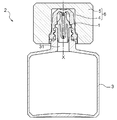
- FIG. 1 the whole sectional view of the eye drop container 2 of this embodiment is shown.
- the ophthalmic container 2 is fitted into a container body 3 having a quadrangular prism shape for containing a liquid, an inner plug 1 attached to the container body 3, a cup-shaped inner lid 4 and an inner lid 4, and the outer shape is a rectangular column shape. And a cap 6 formed by the outer lid 5.
- the container body 3 is manufactured using a resin such as PET (polyethylene terephthalate), and the outer lid 5 is manufactured using an ethylene-based resin or the like. Further, the inner plug 1 and the inner lid 4 are manufactured using a resin such as polypropylene or polyethylene that is not easily deteriorated by electron beam sterilization.
- the resin material is not limited to this, and can be appropriately selected.
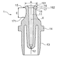
- FIGS. 2 and 4 are a sectional view and an enlarged view of the inner plug 1 in a side sectional view of the nozzle portion 11, and
- FIG. 3 is a perspective view of the inner plug 1.
- the inner plug 1 includes a cylindrical nozzle portion 11, a throttle portion 12 that restricts the flow rate of the liquid at the proximal end of the nozzle portion 11, and an axis X of the nozzle portion 11. It has a cylindrical outer peripheral wall portion 13 formed on the outer side of the base end side from the vicinity of the middle, and a flange portion 14 projecting radially outward at the upper end of the outer peripheral wall portion 13.
- the inner plug 1 is manufactured separately from the container main body 3, and when the upper end surface of the liquid injection port 31 of the container main body 3 is inserted until it comes into contact with the flange portion 14, the outer peripheral surface of the outer peripheral wall portion 13 and the liquid injection port 31.
- the inner peripheral surface is fitted and fixed to the container body 3.
- the container main body 3 and the outer peripheral wall part 13 may be integrally formed, and the nozzle part 11 may be internally fitted.
- the nozzle portion 11 has a diameter-enlarged portion 15 having an outer diameter that extends in the radially outward direction with respect to the axis X of the nozzle portion 11 at the tip of the nozzle portion 11.
- the tip of the nozzle part 11 is approximately 1/3 to 1/5 in the direction parallel to the axis X of the nozzle part 11 assuming that the nozzle part 11 is divided into the range of the tip, middle, and base. Points to the range.
- the enlarged diameter portion 15 is a position that protrudes most along the liquid injection direction in the tip of the nozzle portion 11, and a position closest to the axis X is the most advanced position 161.
- the inner peripheral surface has a linearly widened portion 18 that expands the inner diameter toward the tip end side and is connected to the tip end outer region 16.
- the constricted region 17 refers to a range confined inward from the maximum outer diameter position 162, that is, a range having an outer diameter smaller than the outer diameter of the maximum outer diameter position 162.
- the maximum outer diameter dimension A of the enlarged diameter portion 15 is 3.6 mm
- the width dimension B in the direction perpendicular to the axis X of the tip outer region 16 is 0.7 mm
- the tip outer side is the tip outer side.
- the height dimension C parallel to the axis X of the region 16 is 0.6 mm
- the constriction angle is the angle formed by the tangential direction of the constricted region 17 at the maximum outer diameter position 162 and the direction parallel to the axis X of the nozzle portion 11. ⁇ is set to 30 degrees.
- a constriction width D which is an outer diameter difference in a direction perpendicular to the axis X between the minimum outer diameter position 165 and the maximum outer diameter position 162 where the outer diameter dimension of the constricted region 17 is minimum, is set to 0.3 mm. It is.
- the constricted region 17 is formed from the maximum outer diameter position 162 to the proximal end side of the nozzle portion 11 over the range of the height dimension C or more of the distal end outer region 16.
- the constriction height E which is a distance parallel to, is about 4 mm, and is set to be as large as about 7 times the height dimension C of the tip outer region 16.
- the contour of the tip outer region 16 is configured such that the curvature increases as it approaches the maximum outer diameter position 162.
- the curved radius R1 of the first rounded portion 163 formed on the widened portion 18 side is 0.7 mm
- the curved radius R2 of the second rounded portion 164 formed on the maximum outer diameter position 162 side is 0.5 mm. It is set to. That is, the outline of the distal end outer region 16 is formed by a curve having a center of curvature on the axis X side.
- the droplet volume of the eye dropper container 2 is determined according to the maximum outer diameter dimension A of the enlarged diameter portion 15, and the smaller the maximum outer diameter dimension A is, the smaller the droplet volume is. The larger the diameter dimension A, the larger the droplet amount. Further, if the maximum outer diameter dimension A of the enlarged diameter portion 15 is the same, the droplet amount is determined according to the surface tension and viscosity of the liquid. The smaller the surface tension, the smaller the droplet amount and the larger the surface tension. Droplet volume increases. Thus, when the surface tension of the liquid (about 36 to about 72.8 mN / m) and the required droplet amount (about 20 to about 45 mg) are taken into consideration, the maximum outer diameter A of the enlarged diameter portion 15 is 2.
- the droplet amount is about 25 mg with respect to the liquid surface tension of 36.0 mN / m.
- the maximum outer diameter dimension A is set to 3.6 mm.
- the liquid coming out of the nozzle portion 11 comes into contact with the surface of the enlarged diameter portion 15 due to wettability and becomes granular due to the surface tension of the liquid, and the weight of the liquid is maintained by wettability. When it becomes impossible, it drops as a droplet. At this time, if the member area in which the liquid discharged from the nozzle part 11 can spread in the radial direction is limited, the remaining liquid at the tip of the nozzle part 11 after the liquid is dropped in a spherical shape can be reduced. .
- the width B of the tip outer region 16 is 1.0 mm or less and the height C to 1.0 mm or less, while the maximum outer diameter A is 3.6 mm.
- the member area in which the liquid discharged from the nozzle portion 11 can spread in the radial direction can be limited. That is, by setting the width dimension B and the height dimension C as small as 0.3 times or less with respect to the maximum outer diameter dimension A, the liquid contact surface area when the liquid droplet falls is reduced, so that the expanded diameter portion 15 It is hard for liquid to remain on the surface.
- the liquid residue at the tip of the nozzle part 11 can be reduced by setting the width dimension B and the height dimension C of the tip outer region 16 to be equal to or less than the predetermined values as described above, the nozzle part like the eye drop container 2 or the like.
- the tip 11 is used close to the eye, if the tip outer region 16 is made too small, the tip of the nozzle portion 11 becomes sharp and gives a feeling of pressure.
- the thickness of the tip of the nozzle portion 11 is ensured to be equal to or greater than a certain dimension, and for example, resin molding is facilitated and the range of shape selection is widened.
- the curved radius R1 of the first rounded portion 163 is set to 0.7 mm
- the curved radius R2 of the second rounded portion 164 is set to 0.5 mm
- the curvature of the tip outer region 16 is configured to increase as it approaches the maximum outer diameter position 162. is there. That is, as the position is farther from the opening at the tip of the nozzle part 11, the surface normal direction deviates from the liquid injection direction. Therefore, even if the liquid tries to go around the tip of the nozzle part 11, the liquid is less likely to follow the surface of the enlarged diameter part 15 as the distance from the opening increases, and the liquid droplets are easily maintained in a spherical shape.
- the liquid at the tip of the nozzle part 11 is brought into the nozzle part 11 when the force pushing the container body 3 is loosened. It is important to make it easy to return. As described above, by restricting the width dimension B and the height dimension C of the distal end outer region 16 to be small, it is possible to improve the return characteristics of the liquid, and it is possible to obtain the inner plug 1 with good liquid drainage. In addition, by forming the spreading portion 18 on the inner peripheral surface of the tip of the nozzle portion 11, the angle of the corner portion that should be overcome for the liquid that has exited the tip of the nozzle portion 11 to return to the inside of the nozzle portion 11 is reduced. For this reason, the return characteristic of the liquid can be further improved.
- the constriction angle ⁇ of the constricted region 17 is set to be greater than 0 degree and equal to or less than 90 degrees so that the contour of the tip outer region 16 and the contour of the constricted region 17 are discontinuous. Just do it. More preferably, it is larger than 0 degree and 45 degrees or less, and in this case, processing such as die cutting using a mold becomes easy.
- the constriction width D of the constricted region 17 is preferably set to 0.1 mm or more and 1 mm or less. More preferably, it is 0.2 mm or more and 0.5 mm or less. Further, the constriction height E of the constriction region 17 is equal to or greater than the height dimension C of the distal end outer region 16 as described above. As described above, since the constricted region 17 is formed larger on the proximal end side than the maximum outer diameter position 162 at the distal end of the nozzle portion 11, the liquid pushed out to the distal outer region 16 exceeds the maximum outer diameter position 162. Can be prevented from getting wet to the base end side of the nozzle.
- the width dimension B and the height dimension B of the distal end outer region 16 corresponding to the maximum outer diameter dimension A of the enlarged diameter portion 15 can be effectively reduced in accordance with the wettability of the liquid.
- the dimension C is determined. That is, the width B is 0.75 mm or less to 1.2 mm or less so that the width B and the height C are 0.3 times or less with respect to the maximum outer diameter A ranging from 2.5 mm to 4 mm.
- the height dimension C is set in the range of 0.75 mm or less to 1.2 mm or less. *
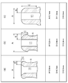
- FIG. 5 is a cross-sectional view comparing the dimensions of the inner plug 1 according to the present invention and other inner plugs in a side sectional view of the nozzle portion 11.
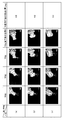
- FIG. 6 is a comparison between the eye drop container 2 according to the present invention and other eye drop containers equipped with the inner stoppers (b) and (c) shown in FIG. It is a photograph which shows.
- FIG. 5 is a schematic diagram comparing the maximum outer diameter A, the width B of the tip outer region, and the height C of the inner plug (a), other inner plugs (b), and (c) in this embodiment.
- Figures and dimensional values are shown.
- the maximum outer diameter dimension A is in the range of 2.5 mm to 4 mm
- the width dimension B and the height dimension C are 0.3 times or less than the maximum outer diameter dimension A.
- the inner plug (b) has a maximum outer diameter A of 6.2 mm, a width B of 2.0 mm, and a height C of 2.3 mm.
- the inner plug (c) has a maximum outer diameter.
- the dimension A is 6.1 mm
- the width dimension B is 1.8 mm
- the height dimension C is 6.5 mm.
- the degree of remaining liquid at the time of dropping is compared and verified.
- the eye drop container is fixed to the angle adjusting device in three patterns of 30 degrees, 50 degrees, and 70 degrees among the angles inclined from 30 degrees to 70 degrees with respect to the injection direction considered as a normal eye drop angle.
- the container weight after the body part of the container body was pressed with a finger and dropped 10 times and the container weight after wiping off the liquid residue at the tip of the nozzle part were measured, and the average value of the difference between the two was measured. The remaining amount.
- the inner plugs (b) and (c) get wet because the liquid spreads outward from the tip of the nozzle portion as the dropping angle is inclined to 30 degrees, 50 degrees, and 70 degrees.
- the liquidity is increased and a lot of liquid residue is generated.
- the inner plug (a) is tilted at a drop angle of 30 °, 50 °, and 70 °, the liquid is held in the tip outer region 16 having a small surface area, so that the wettability is small and the liquid remaining is almost zero. Close to.
- the nozzle By setting the maximum outer diameter dimension A within the range of 2.5 mm to 4 mm and the width dimension B and height dimension C to 0.3 times or less with respect to the maximum outer diameter dimension A, the nozzle It turns out that the liquid residue of the front-end
- the nozzle portion 11 can be used even if it is tilted at a dropping angle of 30 degrees, 50 degrees, and 70 degrees if the dimensional shape is optimal.
- the amount of liquid remaining at the tip is small.
- the dropping angle is set to 50.
- the angle is increased from 70 degrees to 70 degrees, the liquid remaining amount at the tip of the nozzle portion 11 hardly increases.
- the inner plug 1 is mounted on the container main body 3, but the nozzle portion 11 may be integrally formed on the distal end portion of the container main body 3 as shown in FIG. 7.
- the configuration of the tip of the nozzle portion 11 is the same as that of the above-described embodiment, and thus the description thereof is omitted.
- the same reference numerals as those in the above-described embodiment are given, but there is no particular limitation.
- FIG. 7 is an enlarged view of the distal end portion of the eye drop container 2.
- the eye drop container 2 includes a container main body 3 that stores a liquid, and a nozzle portion 11 that is integrally formed at the tip of the container main body 3.
- a method for integrally forming the nozzle portion 11 at the distal end portion of the container body 3 is disclosed in Japanese Patent Application Laid-Open No. 2001-120039.
- the ophthalmic container 2 integrated with the nozzle unit 11 in the present embodiment has good liquid drainage and can effectively suppress liquid residue.
- the inner plug 1 may be formed by fitting an outer cylinder 19 and an inner cylinder 20 as shown in FIG.
- the configuration of the tip of the nozzle portion 11 is the same as in the above-described embodiment.
- the first rounded portion 163 and the second rounded portion 164 are provided so that the curvature increases as the contour of the tip outer region 16 approaches the maximum outer diameter position 162. good. In this case, compared to providing different curvatures, the processing of the inner plug 1 is facilitated, and the processing accuracy is increased.
- the curvature change point of the front end outer region 16 is not limited to one place, and a plurality of places may be provided.
- the linear spreading portion 18 is provided on the inner peripheral surface of the nozzle portion 11, but it may be a curved spreading portion 18, and the tip of the nozzle portion 11 may be angular without providing the spreading portion 18. It is good also as a shape.
- the present invention can be used for an inner stopper to be attached to a liquid injection port of a container, a liquid container having the inner stopper, and a liquid container having a nozzle tip structure.
Landscapes
- Engineering & Computer Science (AREA)
- Mechanical Engineering (AREA)
- Closures For Containers (AREA)
- Details Of Rigid Or Semi-Rigid Containers (AREA)
- Containers And Packaging Bodies Having A Special Means To Remove Contents (AREA)
Abstract
液切れが良く、液残りを効果的に抑制できる中栓、ノズルの先端構造及び液体収容容器を提供する。ノズル部の先端に、外径がノズル部の軸芯に対して径外方向に広がった拡径部を備え、拡径部は、ノズル部の側断面視において、最先端位置から最大外径位置までの先端外側領域と、最大外径位置からノズル部の基端側に連接されたくびれ領域とを有し、拡径部の最大外径寸法が、2.5mmから4mmの範囲内に設定されると共に、先端外側領域について、軸芯に垂直な方向の幅寸法と軸芯に平行な高さ寸法とが、0.3mm以上且つ最大外径寸法に対して0.3倍以下に設定されている。
Description
本発明は、液体を収容する容器本体に装着され、液体を注液する筒状のノズル部を備えた中栓とその中栓を備えた液体収容容器、及び液体を収容する容器本体の先端部に形成された、液体を注液する筒状のノズルの先端構造とその構造を有する液体収容容器に関する。
従来の中栓としては、例えば、点眼容器に用いられるものであって、筒状のノズル部の先端に、ノズル部の軸芯に対して径外方向に半球状に形成される半球状部と、半球状部の最大外径部分の外周に形成したリング状突起と、リング状突起から内側にくびれたくびれ部とを設けたものがある(例えば、特許文献1)。
この中栓は、容器本体を傾けて注液するとき、ノズル部から出た液体が半球状部の表面を介して容器本体の側に回り込むのを、リング状突起によって堰き止めようとするものである。
しかしながら、上記従来の中栓では、半球状部を設けるために軸芯方向の内径と外径との差が大きくなり、ノズル部の先端部を形成する表面積が大きくなる。また、リング状突起によって液体の回り込みを防止しようとするから、このリング状突起の分だけ先端部の外径が大きくなる。この結果、中栓の先端部の面積がさらに大きくなり、表面の濡れ性に基づいて注液後の液体が表面に残留し易くなる。
また、先端形状が、半球状部の周囲にリング状突起が設けられたものであるため、半球状部とリング状突起との境界位置が凹状となる。この凹状部には注液時の液体が残留し易くなる。
さらに、上記従来の中栓では、ノズル部の内周面が、側断面視において中栓の先端部まで直線状に形成されている。よって、当該内周面と半球状部との境界が尖った角部となる。この角部は、注液後に液体が中栓の内部に戻ろうとするときの障害となる。その結果、注液後の液体が半球状部の表面に残留しやすくなる。
また、先端形状が、半球状部の周囲にリング状突起が設けられたものであるため、半球状部とリング状突起との境界位置が凹状となる。この凹状部には注液時の液体が残留し易くなる。
さらに、上記従来の中栓では、ノズル部の内周面が、側断面視において中栓の先端部まで直線状に形成されている。よって、当該内周面と半球状部との境界が尖った角部となる。この角部は、注液後に液体が中栓の内部に戻ろうとするときの障害となる。その結果、注液後の液体が半球状部の表面に残留しやすくなる。
本発明は上述した背景に鑑みてなされたものであり、液切れが良く、液残りを効果的に抑制できる中栓とその中栓を備えた液体収容容器、及びノズルの先端構造とその構造を備えた液体収容容器を提供することにある。
本発明に係る中栓の特徴構成は、液体を収容する容器本体に装着され、前記液体を注液する筒状のノズル部を備えた中栓であって、
前記ノズル部の先端に、外径が前記ノズル部の軸芯に対して径外方向に広がった拡径部を備え、
当該拡径部は、前記ノズル部の側断面視において、前記ノズル部の先端のうち注液方向に沿って最も突出した位置であって、最も前記軸芯に近い位置を最先端位置としたとき、当該最先端位置から前記拡径部の最大外径位置までの先端外側領域と、前記最大外径位置から前記ノズル部の基端側に連接されたくびれ領域とを有し、
前記拡径部の最大外径寸法が、2.5mmから4mmの範囲内に設定されると共に、
前記先端外側領域について、前記軸芯に垂直な方向の幅寸法と前記軸芯に平行な高さ寸法とが、0.3mm以上且つ前記最大外径寸法に対して0.3倍以下に設定される点にある。
前記ノズル部の先端に、外径が前記ノズル部の軸芯に対して径外方向に広がった拡径部を備え、
当該拡径部は、前記ノズル部の側断面視において、前記ノズル部の先端のうち注液方向に沿って最も突出した位置であって、最も前記軸芯に近い位置を最先端位置としたとき、当該最先端位置から前記拡径部の最大外径位置までの先端外側領域と、前記最大外径位置から前記ノズル部の基端側に連接されたくびれ領域とを有し、
前記拡径部の最大外径寸法が、2.5mmから4mmの範囲内に設定されると共に、
前記先端外側領域について、前記軸芯に垂直な方向の幅寸法と前記軸芯に平行な高さ寸法とが、0.3mm以上且つ前記最大外径寸法に対して0.3倍以下に設定される点にある。
容器本体を傾けて注液する場合、ノズル部から出た液体は、拡径部の表面に沿って広がり、表面張力によって球状となる。この球状が拡大し、液体の重量が拡径部表面の濡れ性によっても保持できなくなると液滴は先端部から放れて落下する。ノズル部の先端に液体が残留しないようにするには、一旦、拡径部の表面に押し出された液体が、その後、液滴として落下するか、拡径部に残存したのち中栓の内部に戻るかの何れかに必ず区別されるように拡径部の形状を設定しなければならない。
本発明においては、そのために必要な幾つかの要件を特定した。
まず、拡径部の表面に沿って液体が広がる面積を制限するために、拡径部の最大外径寸法を2.5mmから4mmの範囲に限定した。拡径部の寸法の下限を2.5mmに設定したのは、当該寸法が小さ過ぎる場合、所望の一滴量を確保するための注液孔が確保できなくなるからである。
一方、拡径部の上限を4mmに設定したのは、このサイズであれば、所望の一滴量を確保するための注液孔を確保できるうえ、必要な強度を得るために拡径部の領域をある程度の厚さに確保できるからである。また、液体の濡れ性を考慮した場合、拡径部の面積が過大であれば、注液時に拡径部の表面に広がった液体の一部が、液滴の側にも、戻り液体の側にも属さないものとなり、拡径部の表面に残存する液量が増大してしまう。
所望の一滴量を確保しつつ、拡径部に残留する液量を最小限にするために、拡径部の外径寸法は上記のごとく限定される。
まず、拡径部の表面に沿って液体が広がる面積を制限するために、拡径部の最大外径寸法を2.5mmから4mmの範囲に限定した。拡径部の寸法の下限を2.5mmに設定したのは、当該寸法が小さ過ぎる場合、所望の一滴量を確保するための注液孔が確保できなくなるからである。
一方、拡径部の上限を4mmに設定したのは、このサイズであれば、所望の一滴量を確保するための注液孔を確保できるうえ、必要な強度を得るために拡径部の領域をある程度の厚さに確保できるからである。また、液体の濡れ性を考慮した場合、拡径部の面積が過大であれば、注液時に拡径部の表面に広がった液体の一部が、液滴の側にも、戻り液体の側にも属さないものとなり、拡径部の表面に残存する液量が増大してしまう。
所望の一滴量を確保しつつ、拡径部に残留する液量を最小限にするために、拡径部の外径寸法は上記のごとく限定される。
次に、本発明の中栓にあっては、最大外径位置から基端側にくびれ領域を形成するとともに、先端外側領域については、軸芯に垂直な方向の幅寸法と軸芯に平行な高さ寸法とを最大外径寸法に対して0.3倍以下に設定してある。
このようにくびれ領域を設けることで、容器本体を傾けて注液する場合に液体が基端側に回り込むのを有効に阻止することができる。その上で、本構成では、幅寸法と高さ寸法とを規定する。その結果、拡径部の表面積が一定値以下に制限され、注液時に拡径部の表面に押し出された液体は、滴下するか中栓の内部に戻るかの何れかに分類され易くなる。
このようにくびれ領域を設けることで、容器本体を傾けて注液する場合に液体が基端側に回り込むのを有効に阻止することができる。その上で、本構成では、幅寸法と高さ寸法とを規定する。その結果、拡径部の表面積が一定値以下に制限され、注液時に拡径部の表面に押し出された液体は、滴下するか中栓の内部に戻るかの何れかに分類され易くなる。
一方、幅寸法と高さ寸法とが過小であると、ノズル部の先端が尖った形状となって十分な強度が得られなくなる。そのため、蓋部材の脱着に際して先端部が破損し易いものとなる。また、先端部が尖っていると使用者が点眼時に恐怖心を抱くおそれがある。
そこで、先端外側領域の幅寸法及び高さ寸法を0.3mm以上に設定することで、これらの不都合が解消される。また、ノズル部の先端部の厚みが一定寸法以上に確保されることで、例えば樹脂成形なども容易となり、形状選択の幅が広がる。
そこで、先端外側領域の幅寸法及び高さ寸法を0.3mm以上に設定することで、これらの不都合が解消される。また、ノズル部の先端部の厚みが一定寸法以上に確保されることで、例えば樹脂成形なども容易となり、形状選択の幅が広がる。
本発明の中栓にあっては、前記ノズル部の側断面視において、前記先端外側領域の輪郭が曲線で形成されると好適である。
本構成のように先端外側領域の輪郭を曲線で形成することで、円滑な傾斜によって理想的に液滴が落下することになる。つまり、拡径部に押し出された液体は滑らかに成長し、落下時においてもスムーズに離脱し、ノズル部の先端に液残りが発生し難い。
本発明の中栓にあっては、前記ノズル部の先端における内周面が、先端側ほど内径を広げて構成してあると好適である。
本構成のごとく、ノズル部の先端に広がり部を設けることで、ノズル部の先端に一旦押し出された液体が、ノズル部の内部に戻り易くなる。仮に、ノズル部の側断面視において、内周面と先端表面との境界領域において双方の面方向が大きく異なる場合、当該境界領域には角部が形成されることとなる。この角部は、内周面の側に存在する液体からの表面張力が当該角部を越えて先端表面の側に存在する液体に及ぶのを阻害する。よって、このような角部を無くすことにより、一旦、拡径部に押し出された液体の戻り特性が向上して液残りが解消される。
本発明の中栓にあっては、前記ノズル部の側断面視において、前記先端外側領域の輪郭が、前記最大外径位置に近付くほど曲率が大きくなるように構成してあると好適である。
注液時、ノズル部の外部に押し出された液体は、先端外側領域の外側に回り込もうとする。しかし、本構成では、先端外側領域の曲率が最大外径位置に近付くほど大きくなるから、注液口から離れた位置ほど、表面の法線方向が注液方向から乖離する。拡径部に押し出された液体は自身の表面張力によって球状を維持しようとする。このため、液体のうち周辺に位置する液体は球体の側に引かれる。
本構成では、液体の周辺部と当接する拡径部表面の曲率を大きくしているため、濡れ性によって拡径部表面上に広がろうとする傾向を、液体の表面張力によって抑制し易い。このため、液体の広がりが抑えられ、液切れのよい中栓を得ることができる。
本構成では、液体の周辺部と当接する拡径部表面の曲率を大きくしているため、濡れ性によって拡径部表面上に広がろうとする傾向を、液体の表面張力によって抑制し易い。このため、液体の広がりが抑えられ、液切れのよい中栓を得ることができる。
本発明の中栓にあっては、前記くびれ領域は、前記最大外径位置より前記基端側へ前記高さ寸法以上の範囲に亘って形成されると好適である。
例えば、ノズル部の先端において、最大外径位置より径外方向に突出した部位が最大外径位置に近接して形成されている場合、角度を付けて点眼して、仮に最大外径位置を越えて液垂れが発生すると、液垂れした液体が突出部位に付着して液垂れを拡大するおそれがある。
しかし、本構成は、ノズル部の先端において、最大外径位置より基端側にくびれ領域が大きく形成されているので、先端外側領域に押し出された液体が、最大外径位置を越えたとしてもノズルの基端側まで濡れだすことを防止できる。
しかし、本構成は、ノズル部の先端において、最大外径位置より基端側にくびれ領域が大きく形成されているので、先端外側領域に押し出された液体が、最大外径位置を越えたとしてもノズルの基端側まで濡れだすことを防止できる。
本発明に係る液体収容容器の特徴構成は、上記中栓を備えた点にある。
本発明に係るノズルの先端構造の特徴構成は、液体を収容する容器本体の先端部に形成され、前記液体を注液する筒状のノズル部が有するノズルの先端構造であって、
前記ノズル部の先端に、外径が前記ノズル部の軸芯に対して径外方向に広がった拡径部を備え、
当該拡径部は、前記ノズル部の側断面視において、
前記ノズル部の先端のうち注液方向に沿って最も突出した位置であって、最も前記軸芯に近い位置を最先端位置としたとき、当該最先端位置から前記拡径部の最大外径位置までの先端外側領域と、前記最大外径位置から前記ノズル部の基端側に連接されたくびれ領域とを有し、
前記拡径部の最大外径寸法が、2.5mmから4mmの範囲内に設定されると共に、
前記先端外側領域について、前記軸芯に垂直な方向の幅寸法と前記軸芯に平行な高さ寸法とが、0.3mm以上且つ前記最大外径寸法に対して0.3倍以下に設定される点にある。
このノズルの先端構造は、前記ノズル部の側断面視において、前記先端外側領域の輪郭が曲線で形成されると好適である。
また、このノズルの先端構造は、前記ノズル部の先端における内周面が、先端側ほど内径を広げて構成してあると好適である。
また、前記曲線が、前記最大外径位置に近付くほど曲率が大きくなるように構成してあると好適である。
さらに、前記くびれ領域は、前記最大外径位置より前記基端側へ前記高さ寸法以上の範囲に亘って形成されていると好適である。
前記ノズル部の先端に、外径が前記ノズル部の軸芯に対して径外方向に広がった拡径部を備え、
当該拡径部は、前記ノズル部の側断面視において、
前記ノズル部の先端のうち注液方向に沿って最も突出した位置であって、最も前記軸芯に近い位置を最先端位置としたとき、当該最先端位置から前記拡径部の最大外径位置までの先端外側領域と、前記最大外径位置から前記ノズル部の基端側に連接されたくびれ領域とを有し、
前記拡径部の最大外径寸法が、2.5mmから4mmの範囲内に設定されると共に、
前記先端外側領域について、前記軸芯に垂直な方向の幅寸法と前記軸芯に平行な高さ寸法とが、0.3mm以上且つ前記最大外径寸法に対して0.3倍以下に設定される点にある。
このノズルの先端構造は、前記ノズル部の側断面視において、前記先端外側領域の輪郭が曲線で形成されると好適である。
また、このノズルの先端構造は、前記ノズル部の先端における内周面が、先端側ほど内径を広げて構成してあると好適である。
また、前記曲線が、前記最大外径位置に近付くほど曲率が大きくなるように構成してあると好適である。
さらに、前記くびれ領域は、前記最大外径位置より前記基端側へ前記高さ寸法以上の範囲に亘って形成されていると好適である。
本構成によれば、液切れが良く、液残りを効果的に抑制できるノズルの先端構造を提供することができる。
本発明に係る液体収容容器の特徴構成は、上記ノズルの先端構造を有するノズル部が、液体を収容する容器本体の先端部に一体成形される点にある。このため、中栓を別部材として成形する必要がなく、製造コストを低減することが可能である。
以下に、本発明に係る中栓1の実施形態について、図面に基づいて説明する。本実施形態では、中栓1が装着される容器の一例として、点眼容器2として説明する。ただし、以下の実施形態に限定されることなく、その要旨を逸脱しない範囲内で種々の変形が可能である。
図1に、本実施形態の点眼容器2の全体断面図を示す。
点眼容器2は、液体を収容する外形が四角柱状の容器本体3と、容器本体3に装着される中栓1と、カップ状の内蓋4及び内蓋4に嵌合され外形が四角柱状の外蓋5で形成されるキャップ6とを有する。
点眼容器2は、液体を収容する外形が四角柱状の容器本体3と、容器本体3に装着される中栓1と、カップ状の内蓋4及び内蓋4に嵌合され外形が四角柱状の外蓋5で形成されるキャップ6とを有する。
容器本体3は、PET(ポリエチレン・テレフタレート)などの樹脂を用い、外蓋5は、エチレン系樹脂などを用いて製造される。また、中栓1や内蓋4は、ポリプロピレンや電子線滅菌処理で劣化しにくいポリエチレンなどの樹脂を用いて製造される。
なお、樹脂材料はこれに限られるものではなく、適宜選択が可能である。
なお、樹脂材料はこれに限られるものではなく、適宜選択が可能である。
図2~図4を用いて、中栓1の形状を説明する。図2及び図4はノズル部11の側断面視における中栓1の断面図及びその拡大図であり、図3は中栓1の斜視図である。
図2及び図3に示すように、中栓1は、筒状のノズル部11と、ノズル部11の基端に液体の流量を絞る絞り部12と、ノズル部11の軸芯Xに沿った中間付近より基端側の外側に形成された筒状の外周壁部13と、外周壁部13の上端に径方向外側に突出したフランジ部14とを有する。中栓1は、容器本体3とは別に製造され、容器本体3の注液口31の上端面がフランジ部14と当接するまで差込むと、外周壁部13の外周面と注液口31の内周面とが嵌合して容器本体3に固定される。
なお、容器本体3と外周壁部13とを一体で形成し、ノズル部11を内嵌させる構成にしても良い。
なお、容器本体3と外周壁部13とを一体で形成し、ノズル部11を内嵌させる構成にしても良い。
ノズル部11は、ノズル部11の先端に、外径がノズル部11の軸芯Xに対して径外方向に広がった拡径部15を有する。ここで、ノズル部11の先端とは、ノズル部11が先端、中間、基端の範囲に区分されるとして、ノズル部11の軸芯Xに平行な方向における概ね1/3~1/5程度の範囲を指している。
拡径部15は、図4に示すように、ノズル部11の先端のうち注液方向に沿って最も突出した位置であって、最も軸芯Xに近い位置を最先端位置161としたとき、最先端位置161から拡径部15の最大外径位置162までの先端外側領域16と、最大外径位置162からノズル部11の基端側に連接されたくびれ領域17と、ノズル部11先端の内周面が先端側ほど内径を広げて先端外側領域16と連接する直線状の広がり部18と、を有する。ここで、くびれ領域17とは、最大外径位置162より内側に括れている範囲、つまり最大外径位置162の外径寸法より小さい外径寸法を有する範囲を指している。
拡径部15は、図4に示すように、ノズル部11の先端のうち注液方向に沿って最も突出した位置であって、最も軸芯Xに近い位置を最先端位置161としたとき、最先端位置161から拡径部15の最大外径位置162までの先端外側領域16と、最大外径位置162からノズル部11の基端側に連接されたくびれ領域17と、ノズル部11先端の内周面が先端側ほど内径を広げて先端外側領域16と連接する直線状の広がり部18と、を有する。ここで、くびれ領域17とは、最大外径位置162より内側に括れている範囲、つまり最大外径位置162の外径寸法より小さい外径寸法を有する範囲を指している。
本実施形態では、図4に示すように、拡径部15の最大外径寸法Aは3.6mm、先端外側領域16の軸芯Xに垂直な方向の幅寸法Bは0.7mm、先端外側領域16の軸芯Xに平行な高さ寸法Cは0.6mm、最大外径位置162におけるくびれ領域17の接線方向とノズル部11の軸芯Xに平行な方向とのなす角であるくびれ角θは30度に設定してある。また、くびれ領域17の外径寸法が最小となる最小外径位置165と最大外径位置162との軸芯Xに垂直な方向の外径差であるくびれ幅Dは、0.3mmに設定してある。
さらに、図4に示すようにくびれ領域17は、最大外径位置162からノズル部11の基端側に先端外側領域16の高さ寸法C以上の範囲に亘って形成されている。具体的には、図2に示すように、くびれ領域17からノズル部11の基端側において最大外径位置162より径外方向に突出する突出部位171と最大外径位置162との軸芯Xに平行な距離であるくびれ高さEは、約4mmであり先端外側領域16の高さ寸法Cの約7倍と大きく設定している。すなわち、くびれ領域17から基端側へ軸芯Xに沿って延出し、ノズル部11の先端から逸脱した範囲から徐々に拡径し始め、突出部位171より基端側が最大外径位置162より径外方向に突出する。
先端外側領域16の輪郭は、最大外径位置162に近付くほど曲率が大きくなるように構成してある。具体的には、広がり部18側に形成された第1アール部163の曲線半径R1を0.7mm、最大外径位置162側に形成された第2アール部164の曲線半径R2を0.5mmに設定してある。つまり、先端外側領域16の輪郭は、軸芯X側に曲率中心を有する曲線で形成されている。
一般的に、点眼容器2の液滴量は、拡径部15の最大外径寸法Aに応じて決定され、最大外径寸法Aを小さく設定するほど液滴量が少なくなり、逆に最大外径寸法Aを大きく設定するほど液滴量が多くなる。また、拡径部15の最大外径寸法Aが同じであれば、液体の表面張力や粘性に応じて液滴量が決定され、表面張力が小さいほど液滴量が少なく、表面張力が大きいほど液滴量が多くなる。
このように、液体の表面張力(約36~約72.8mN/m)や必要となる液滴量(約20~約45mg)を考慮すると、拡径部15の最大外径寸法Aは2.5mmから4mmの範囲に設定することが好ましい。なお、本実施形態では、点眼容器2を真下に向けた状態(滴下角度0度)で滴下した時、液体の表面張力36.0mN/mに対して、液滴量が約25mgとなるように、最大外径寸法Aを3.6mmに設定している。
このように、液体の表面張力(約36~約72.8mN/m)や必要となる液滴量(約20~約45mg)を考慮すると、拡径部15の最大外径寸法Aは2.5mmから4mmの範囲に設定することが好ましい。なお、本実施形態では、点眼容器2を真下に向けた状態(滴下角度0度)で滴下した時、液体の表面張力36.0mN/mに対して、液滴量が約25mgとなるように、最大外径寸法Aを3.6mmに設定している。
容器本体3を傾けて注液する場合、ノズル部11から出た液体は、濡れ性によって拡径部15の表面に接触しつつ、液体の表面張力によって粒状となり、液体の重量が濡れ性によって保持できなくなると液滴となって落下する。この時、ノズル部11から排出された液体が径方向に広がりうる部材面積を制限すれば、液体が球形状となって滴下された後におけるノズル部11の先端の液残りを低減することができる。
具体的には、最大外径寸法Aが3.6mmに対して、先端外側領域16の幅寸法Bを1.0mm以下、且つ、高さ寸法Cを1.0mm以下と小さく設定することで、ノズル部11から排出された液体が径方向に広がりうる部材面積を制限することができる。すなわち、最大外径寸法Aに対して幅寸法B及び高さ寸法Cを0.3倍以下と小さく設定することで、液滴が落ちる際の接液表面積を少なくすることで、拡径部15の表面に液体が残り難い。
先端外側領域16の幅寸法B及び高さ寸法Cを上述のような所定値以下に設定することでノズル部11先端の液残りを低減することができるものの、点眼容器2などのようにノズル部11先端を眼に近付けて使用する場合、先端外側領域16をあまり小さくしすぎるとノズル部11先端が尖った形状となってしまい、圧迫感を与えてしまう。このため、ノズル部11先端を曲線形状に加工しやすい幅寸法B及び高さ寸法Cを0.3mm以上に設定するのが好ましく、圧迫感を軽減できる。
また、この寸法であれば、ノズル部11先端の厚みが一定寸法以上に確保され、例えば樹脂成形なども容易となって形状選択の幅が広がる。
また、この寸法であれば、ノズル部11先端の厚みが一定寸法以上に確保され、例えば樹脂成形なども容易となって形状選択の幅が広がる。
第1アール部163の曲線半径R1を0.7mm、第2アール部164の曲線半径R2を0.5mmに設定し、先端外側領域16の曲率が最大外径位置162に近付くほど大きく構成してある。すなわち、ノズル部11先端の開口から遠い位置ほど、表面の法線方向が注液方向から乖離する。よって、液体がノズル部11先端の周囲に回り込もうとしても、開口から離れるほど液体は拡径部15の表面に追随し難くなり、液滴を球状に維持し易くなる。
このように、先端外側領域16の曲率が最大外径位置162に近付くほど大きく構成することで、ノズル部11先端の径外方向に液体が広がるのを抑制して、液残りとともに液垂れもより一層低減することができる。
このように、先端外側領域16の曲率が最大外径位置162に近付くほど大きく構成することで、ノズル部11先端の径外方向に液体が広がるのを抑制して、液残りとともに液垂れもより一層低減することができる。
一方、液体を注液した後、ノズル部11先端に液体が残らないようにするには、容器本体3を押す力を緩めた際に、ノズル部11先端にある液体がノズル部11の内部に戻り易くすることが重要である。上述のように先端外側領域16の幅寸法B及び高さ寸法Cを小さく制限することで、液体の戻り特性を向上させることができ、液切れの良い中栓1を得ることができる。
また、ノズル部11先端の内周面に広がり部18を形成することで、ノズル部11先端を出た液体がノズル部11内部に戻るための乗越えるべき角部の角度が小さくなる。このため、液体の戻り特性をより一層向上させることができる。
また、ノズル部11先端の内周面に広がり部18を形成することで、ノズル部11先端を出た液体がノズル部11内部に戻るための乗越えるべき角部の角度が小さくなる。このため、液体の戻り特性をより一層向上させることができる。
さらに、拡径部15にくびれ領域17を形成することで、ノズル部11から排出された液体が最大外径位置162から基端側に流れ難くなるので、液垂れを防止できる。なお、液垂れを防止するには、くびれ領域17のくびれ角θを0度より大きく90度以下に設定して、先端外側領域16の輪郭とくびれ領域17の輪郭とが不連続になるようにすれば良い。より好ましくは、0度より大きく45度以下であり、この場合、金型を用いた型抜き等の加工が容易となる。
くびれ領域17のくびれ幅Dは、0.1mm以上1mm以下に設定するのが好ましい。より好ましくは、0.2mm以上0.5mm以下である。また、くびれ領域17のくびれ高さEは、上述したように先端外側領域16の高さ寸法C以上となっている。このようにノズル部11の先端において、最大外径位置162より基端側にくびれ領域17が大きく形成されているので、先端外側領域16に押し出された液体が、最大外径位置162を越えてもノズルの基端側まで濡れだすことが防止できる。
本実施形態では、液体の濡れ性に応じてノズル部11先端の液残りを効果的に低減できるよう、拡径部15の最大外径寸法Aに応じた先端外側領域16の幅寸法B及び高さ寸法Cを決定している。すなわち、最大外径寸法Aの2.5mmから4mmの範囲に対して、幅寸法B及び高さ寸法Cが0.3倍以下となるよう、幅寸法Bを0.75mm以下から1.2mm以下、高さ寸法Cを0.75mm以下から1.2mm以下の範囲で設定する。
続いて、図5及び図6を用いて、容器本体3を傾けた状態で注液した時、最大外径寸法Aに対する幅寸法B及び高さ寸法Cの割合に応じたノズル部11先端の液残り度合いについて比較検証を行う。
図5は、ノズル部11の側断面視における本発明における中栓1と他の中栓との寸法を比較した断面図である。図6は、本発明における点眼容器2と図5に示す中栓(b)、(c)を装着した他の点眼容器とを比較した、容器を傾けた状態で注液した時における液残り度合いを示す写真である。
図5は、ノズル部11の側断面視における本発明における中栓1と他の中栓との寸法を比較した断面図である。図6は、本発明における点眼容器2と図5に示す中栓(b)、(c)を装着した他の点眼容器とを比較した、容器を傾けた状態で注液した時における液残り度合いを示す写真である。
図5には、本実施形態での中栓(a)、他の中栓(b)、(c)における最大外径寸法A、先端外側領域の幅寸法B及び高さ寸法Cを比較した模式図及び寸法値を示している。
中栓(a)では、最大外径寸法Aが2.5mmから4mmの範囲内で、且つ、幅寸法B及び高さ寸法Cが最大外径寸法Aに対して0.3倍以下となっている。
一方、中栓(b)は、最大外径寸法Aが6.2mm、幅寸法Bが2.0mm、高さ寸法Cが2.3mmとなっており、中栓(c)は、最大外径寸法Aが6.1mm、幅寸法Bが1.8mm、高さ寸法Cが6.5mmとなっている。
中栓(a)では、最大外径寸法Aが2.5mmから4mmの範囲内で、且つ、幅寸法B及び高さ寸法Cが最大外径寸法Aに対して0.3倍以下となっている。
一方、中栓(b)は、最大外径寸法Aが6.2mm、幅寸法Bが2.0mm、高さ寸法Cが2.3mmとなっており、中栓(c)は、最大外径寸法Aが6.1mm、幅寸法Bが1.8mm、高さ寸法Cが6.5mmとなっている。
次に、図6を用いて、滴下時の液残り度合いを比較検証する。
まず、滴下試験の方法について説明する。
通常の点眼角度として考えられる注液方向に対して30度から70度傾けた角度のうち、30度、50度、70度の3パターンで、点眼容器を角度調整器具に固定する。次いで、容器本体の胴部を指で押圧して10回滴下した後の容器重量と、ノズル部の先端の液残りを拭き取った後の容器重量とを測定し、双方の差の平均値を液残り量とした。なお、容器に収容される液体は、表面張力が36.0mN/mのものを用いた。
まず、滴下試験の方法について説明する。
通常の点眼角度として考えられる注液方向に対して30度から70度傾けた角度のうち、30度、50度、70度の3パターンで、点眼容器を角度調整器具に固定する。次いで、容器本体の胴部を指で押圧して10回滴下した後の容器重量と、ノズル部の先端の液残りを拭き取った後の容器重量とを測定し、双方の差の平均値を液残り量とした。なお、容器に収容される液体は、表面張力が36.0mN/mのものを用いた。
図6に示すように、滴下角度30度、50度、70度と傾けていくに従って、中栓(b)、(c)は、液体がノズル部の先端の径外方向に広がっていくので濡れ性が高まり、液残りが多く発生している。一方、中栓(a)は、滴下角度30度、50度、70度と傾けても、小さい表面積を持った先端外側領域16で液体が保持されるので濡れ性が小さく、液残りがほぼゼロに近い。
このように、最大外径寸法Aを2.5mmから4mmの範囲内、且つ、幅寸法B及び高さ寸法Cを最大外径寸法Aに対して0.3倍以下に設定することで、ノズル部11先端の液残りを効果的に低減できることが分かる。
また、くびれを設けていない中栓(c)は、滴下角度30度、50度、70度と傾けていくに従ってノズル部の基端側に液垂れが発生しているが、中栓(a)は、くびれ領域17に液垂れが発生していないことが分かる。
このように、最大外径寸法Aを2.5mmから4mmの範囲内、且つ、幅寸法B及び高さ寸法Cを最大外径寸法Aに対して0.3倍以下に設定することで、ノズル部11先端の液残りを効果的に低減できることが分かる。
また、くびれを設けていない中栓(c)は、滴下角度30度、50度、70度と傾けていくに従ってノズル部の基端側に液垂れが発生しているが、中栓(a)は、くびれ領域17に液垂れが発生していないことが分かる。
続いて、表1を用いて、最大外径寸法A、幅寸法B及び高さ寸法Cを変化させた場合の液残り量について説明する。滴下試験の方法及び液残り量の測定方法は上述の方法と同様である。中栓(a1)~(a3)のノズル部11の先端の基本形状は図5に示す中栓(a)と同様であり、最大外径寸法A、幅寸法B及び高さ寸法Cを変化させた。また、比較例(X)として中栓(a)~(a3)の最適寸法範囲を超える最大外径寸法Aを4.5mmに設定し、液体が広がる部材面積を大きくした場合の液残り量について検証する。さらに、中栓(b)、(c)における測定結果を、比較例(b)、比較例(c)とする。

表1の中栓(a)~(a3)における液残り量の測定結果から分かるように、最適な寸法形状であれば、滴下角度30度、50度、70度と傾けても、ノズル部11先端の液残り量が少ない。また、中栓(a2)、(a3)のように最大外径寸法Aに対して先端外側領域16の幅寸法B及び高さ寸法Cを上限値付近に設定した場合においても、滴下角度を50度から70度に大きくした際、ノズル部11先端の液残り量はほとんど増大しない。
一方、比較例(X)のように、最大外径寸法Aが4.0mmを超えた場合、滴下角度を50度から70度に大きくした際、液残り量が大きく増大する結果となった。
さらに、比較例(b)~(c)においては、最大外径寸法Aが4.0mmを超え、且つ、幅寸法B及び/又は高さ寸法Cが0.3倍以上であるため、滴下角度を50度から70度に大きくした際、液残り量が著しく増大する結果となった。
このように、最大外径寸法Aが2.5mmから4mmの範囲内に対して、幅寸法B及び高さ寸法Cを0.3倍以下に設定することで、ノズル部11先端の液残りを確実に低減できることが検証された。
一方、比較例(X)のように、最大外径寸法Aが4.0mmを超えた場合、滴下角度を50度から70度に大きくした際、液残り量が大きく増大する結果となった。
さらに、比較例(b)~(c)においては、最大外径寸法Aが4.0mmを超え、且つ、幅寸法B及び/又は高さ寸法Cが0.3倍以上であるため、滴下角度を50度から70度に大きくした際、液残り量が著しく増大する結果となった。
このように、最大外径寸法Aが2.5mmから4mmの範囲内に対して、幅寸法B及び高さ寸法Cを0.3倍以下に設定することで、ノズル部11先端の液残りを確実に低減できることが検証された。
[別実施形態1]
上述の実施形態では、中栓1を容器本体3に装着する構成にしたが、図7に示すように、ノズル部11を容器本体3の先端部に一体成形しても良い。以下、ノズル部11の先端の構成は上述の実施形態と同様であるため、説明を省略する。なお、図面の理解を助けるため、上述の実施形態と同様の符号を付して説明するが、特に限定されるものではない。
上述の実施形態では、中栓1を容器本体3に装着する構成にしたが、図7に示すように、ノズル部11を容器本体3の先端部に一体成形しても良い。以下、ノズル部11の先端の構成は上述の実施形態と同様であるため、説明を省略する。なお、図面の理解を助けるため、上述の実施形態と同様の符号を付して説明するが、特に限定されるものではない。
図7は、点眼容器2の先端部を拡大した図である。点眼容器2は、液体を収容する容器本体3と、容器本体3の先端部に一体形成されるノズル部11とを有する。
例えば、ノズル部11を容器本体3の先端部に一体成形する方法は、特開2001-120639号公報に示されている。
例えば、ノズル部11を容器本体3の先端部に一体成形する方法は、特開2001-120639号公報に示されている。
本実施形態におけるノズル部11一体型の点眼容器2は、ノズル部11の先端構造が上述の実施形態と同様の構成であるので、液切れが良く、液残りを効果的に抑制できる。
[別実施形態2]
上述の実施形態における中栓1に代えて、図8に示すように、外筒19と内筒20とを嵌合することで中栓1を形成してもよい。ノズル部11先端の構成は、上述の実施形態と同様である。
上述の実施形態における中栓1に代えて、図8に示すように、外筒19と内筒20とを嵌合することで中栓1を形成してもよい。ノズル部11先端の構成は、上述の実施形態と同様である。
[その他の実施形態]
(1)本実施形態では、先端外側領域16の輪郭が最大外径位置162に近付くほど曲率が大きくなるよう第1アール部163と第2アール部164とを設けたが、曲率を一定としても良い。この場合、異なる曲率を設けるのに比べ、中栓1の加工が容易となり、加工精度が高まる。なお、先端外側領域16の曲率変化点は1箇所に限らず、複数箇所設けても良い。
(2)本実施形態では、ノズル部11の内周面に直線状の広がり部18を設けたが、曲線状の広がり部18としても良いし、広がり部18を設けずノズル部11先端を角形状としても良い。
(1)本実施形態では、先端外側領域16の輪郭が最大外径位置162に近付くほど曲率が大きくなるよう第1アール部163と第2アール部164とを設けたが、曲率を一定としても良い。この場合、異なる曲率を設けるのに比べ、中栓1の加工が容易となり、加工精度が高まる。なお、先端外側領域16の曲率変化点は1箇所に限らず、複数箇所設けても良い。
(2)本実施形態では、ノズル部11の内周面に直線状の広がり部18を設けたが、曲線状の広がり部18としても良いし、広がり部18を設けずノズル部11先端を角形状としても良い。
本発明は、容器の注液口に装着される中栓とその中栓を備えた液体収容容器及びノズルの先端構造を備えた液体収容容器に利用可能である。
1 中栓
11 ノズル部
15 拡径部
16 先端外側領域
161 最先端位置
162 最大外径位置
17 くびれ領域
18 広がり部
A 最大外径寸法
B 幅寸法
C 高さ寸法
D くびれ幅
E くびれ高さ
θ くびれ角
X 軸芯
2 点眼容器
3 容器本体
11 ノズル部
15 拡径部
16 先端外側領域
161 最先端位置
162 最大外径位置
17 くびれ領域
18 広がり部
A 最大外径寸法
B 幅寸法
C 高さ寸法
D くびれ幅
E くびれ高さ
θ くびれ角
X 軸芯
2 点眼容器
3 容器本体
Claims (12)
- 液体を収容する容器本体に装着され、前記液体を注液する筒状のノズル部を備えた中栓であって、
前記ノズル部の先端に、外径が前記ノズル部の軸芯に対して径外方向に広がった拡径部を備え、
当該拡径部は、前記ノズル部の側断面視において、
前記ノズル部の先端のうち注液方向に沿って最も突出した位置であって、最も前記軸芯に近い位置を最先端位置としたとき、当該最先端位置から前記拡径部の最大外径位置までの先端外側領域と、前記最大外径位置から前記ノズル部の基端側に連接されたくびれ領域とを有し、
前記拡径部の最大外径寸法が、2.5mmから4mmの範囲内に設定されると共に、
前記先端外側領域について、前記軸芯に垂直な方向の幅寸法と前記軸芯に平行な高さ寸法とが、0.3mm以上且つ前記最大外径寸法に対して0.3倍以下に設定される中栓。 - 前記ノズル部の側断面視において、前記先端外側領域の輪郭が曲線で形成される請求項1に記載の中栓。
- 前記ノズル部の先端における内周面が、先端側ほど内径を広げて構成してある請求項1又は2に記載の中栓。
- 前記ノズル部の側断面視において、前記先端外側領域の輪郭が、前記最大外径位置に近付くほど曲率が大きくなるように構成してある請求項1から3のいずれか一項に記載の中栓。
- 前記くびれ領域は、前記最大外径位置より前記基端側へ前記高さ寸法以上の範囲に亘って形成される請求項1から4のいずれか一項に記載の中栓。
- 請求項1から5のいずれか一項に記載の中栓を備えた液体収容容器。
- 液体を収容する容器本体の先端部に形成され、前記液体を注液する筒状のノズル部が有するノズルの先端構造であって、
前記ノズル部の先端に、外径が前記ノズル部の軸芯に対して径外方向に広がった拡径部を備え、
当該拡径部は、前記ノズル部の側断面視において、
前記ノズル部の先端のうち注液方向に沿って最も突出した位置であって、最も前記軸芯に近い位置を最先端位置としたとき、当該最先端位置から前記拡径部の最大外径位置までの先端外側領域と、前記最大外径位置から前記ノズル部の基端側に連接されたくびれ領域とを有し、
前記拡径部の最大外径寸法が、2.5mmから4mmの範囲内に設定されると共に、
前記先端外側領域について、前記軸芯に垂直な方向の幅寸法と前記軸芯に平行な高さ寸法とが、0.3mm以上且つ前記最大外径寸法に対して0.3倍以下に設定されるノズルの先端構造。 - 前記ノズル部の側断面視において、前記先端外側領域の輪郭が曲線で形成される請求項7に記載のノズルの先端構造。
- 前記ノズル部の先端における内周面が、先端側ほど内径を広げて構成してある請求項7又は8に記載のノズルの先端構造。
- 前記ノズル部の側断面視において、前記先端外側領域の輪郭が、前記最大外径位置に近付くほど曲率が大きくなるように構成してある請求項7から9のいずれか一項に記載のノズルの先端構造。
- 前記くびれ領域は、前記最大外径位置より前記基端側へ前記高さ寸法以上の範囲に亘って形成される請求項7から10のいずれか一項に記載のノズルの先端構造。
- 請求項7から11のいずれか一項に記載のノズルの先端構造を有するノズル部が、液体を収容する容器本体の先端部に一体成形される液体収容容器。
Priority Applications (1)
| Application Number | Priority Date | Filing Date | Title |
|---|---|---|---|
| CN201480004556.6A CN104884364B (zh) | 2013-01-11 | 2014-01-10 | 内塞和具备该内塞的液体收容容器、以及喷嘴的前端构造和具备该构造的液体收容容器 |
Applications Claiming Priority (2)
| Application Number | Priority Date | Filing Date | Title |
|---|---|---|---|
| JP2013-003767 | 2013-01-11 | ||
| JP2013003767 | 2013-01-11 |
Publications (1)
| Publication Number | Publication Date |
|---|---|
| WO2014109376A1 true WO2014109376A1 (ja) | 2014-07-17 |
Family
ID=51167023
Family Applications (1)
| Application Number | Title | Priority Date | Filing Date |
|---|---|---|---|
| PCT/JP2014/050274 Ceased WO2014109376A1 (ja) | 2013-01-11 | 2014-01-10 | 中栓とその中栓を備えた液体収容容器、及びノズルの先端構造とその構造を備えた液体収容容器 |
Country Status (4)
| Country | Link |
|---|---|
| JP (1) | JP6420544B2 (ja) |
| CN (1) | CN104884364B (ja) |
| TW (1) | TWI608970B (ja) |
| WO (1) | WO2014109376A1 (ja) |
Families Citing this family (4)
| Publication number | Priority date | Publication date | Assignee | Title |
|---|---|---|---|---|
| JP6577476B2 (ja) * | 2014-09-02 | 2019-09-18 | 阪神化成工業株式会社 | 滴下用ノズル及び滴下具 |
| JP6733134B2 (ja) * | 2015-03-19 | 2020-07-29 | 東洋製罐グループホールディングス株式会社 | ノズル |
| CN208264912U (zh) * | 2018-03-28 | 2018-12-21 | 深圳市通产丽星股份有限公司 | 一种点滴软管 |
| JP7405104B2 (ja) * | 2021-01-29 | 2023-12-26 | Jfeスチール株式会社 | 液体注出用ノズルおよび液体注出用ノズル付き液体容器 |
Citations (4)
| Publication number | Priority date | Publication date | Assignee | Title |
|---|---|---|---|---|
| JP2004123220A (ja) * | 2002-08-06 | 2004-04-22 | Takeuchi Press Ind Co Ltd | 容器の口部 |
| JP3145715U (ja) * | 2008-08-06 | 2008-10-16 | 常盤薬品工業株式会社 | 液垂れおよび臭気漏れを防止する容器用口構造 |
| JP2009249036A (ja) * | 2008-04-01 | 2009-10-29 | Kitano Seisaku Kk | 滴下中栓 |
| WO2011037174A1 (ja) * | 2009-09-24 | 2011-03-31 | 千寿製薬株式会社 | 薬液容器用ノズル |
Family Cites Families (4)
| Publication number | Priority date | Publication date | Assignee | Title |
|---|---|---|---|---|
| US5763454A (en) * | 1995-06-06 | 1998-06-09 | Pfizer, Inc. | Crystal form of anhydrous 7-( 1α,5α,6α!-6-amino-3-azabicyclo 3.1.0!hex-3-yl)-6-fluoro-1-(2,4-difluorophenyl)-1,4-dihydro-4-oxo-1,8 naphthyridine-3-carboxylic acid, methanessulfonic acid salt |
| JP3922910B2 (ja) * | 2001-10-31 | 2007-05-30 | 参天製薬株式会社 | 段差部を備えた点眼容器 |
| JP3971329B2 (ja) * | 2002-10-23 | 2007-09-05 | ロート製薬株式会社 | 液体用容器のノズル構造 |
| JP2008174268A (ja) * | 2007-01-18 | 2008-07-31 | Shinko Chemical Co Ltd | 薬液容器の中栓 |
-
2014
- 2014-01-10 WO PCT/JP2014/050274 patent/WO2014109376A1/ja not_active Ceased
- 2014-01-10 CN CN201480004556.6A patent/CN104884364B/zh active Active
- 2014-01-10 JP JP2014002838A patent/JP6420544B2/ja active Active
- 2014-01-10 TW TW103100960A patent/TWI608970B/zh active
Patent Citations (4)
| Publication number | Priority date | Publication date | Assignee | Title |
|---|---|---|---|---|
| JP2004123220A (ja) * | 2002-08-06 | 2004-04-22 | Takeuchi Press Ind Co Ltd | 容器の口部 |
| JP2009249036A (ja) * | 2008-04-01 | 2009-10-29 | Kitano Seisaku Kk | 滴下中栓 |
| JP3145715U (ja) * | 2008-08-06 | 2008-10-16 | 常盤薬品工業株式会社 | 液垂れおよび臭気漏れを防止する容器用口構造 |
| WO2011037174A1 (ja) * | 2009-09-24 | 2011-03-31 | 千寿製薬株式会社 | 薬液容器用ノズル |
Also Published As
| Publication number | Publication date |
|---|---|
| CN104884364B (zh) | 2017-10-03 |
| JP6420544B2 (ja) | 2018-11-07 |
| TWI608970B (zh) | 2017-12-21 |
| TW201507937A (zh) | 2015-03-01 |
| JP2014148355A (ja) | 2014-08-21 |
| CN104884364A (zh) | 2015-09-02 |
Similar Documents
| Publication | Publication Date | Title |
|---|---|---|
| EP2287083A1 (en) | Liquid container | |
| JP6420544B2 (ja) | 中栓とその中栓を備えた液体収容容器、及びノズルの先端構造とその構造を備えた液体収容容器 | |
| JP3648487B2 (ja) | 分注装置用ノズルチップ | |
| US5464048A (en) | Liquid dispenser bottles with reservoirs for droppers | |
| AU2008255764B2 (en) | Synthetic resin bottle | |
| EP2266887B1 (en) | Liquid container | |
| JP3628242B2 (ja) | 窪み部形成点眼容器 | |
| JP4796307B2 (ja) | 滴下用のノズル孔構造、このノズル孔構造を有する滴下ノズル | |
| WO2011037174A1 (ja) | 薬液容器用ノズル | |
| JP2013230301A (ja) | 薬液容器用ノズル | |
| JP6452252B2 (ja) | 容器 | |
| JP4397600B2 (ja) | 薬液容器の中栓 | |
| JP6460379B2 (ja) | 滴下ノズル | |
| JPWO2007094243A1 (ja) | 容器 | |
| CN110475725B (zh) | 收缩包装用容器 | |
| EP3117853B1 (en) | Applicator that allows easy mounting and removal of cartridge | |
| US20140048569A1 (en) | Drop dispenser | |
| WO2015064596A1 (ja) | 点眼用容器 | |
| JP5162422B2 (ja) | 計量キャップ | |
| ES2858430T3 (es) | Botella con pico vertedor y vaso dosificador | |
| JP2004256149A (ja) | 包装用容器および中栓 | |
| JP4457013B2 (ja) | 薬液容器、及び薬液容器用の抽出ノズル | |
| WO2015030249A1 (ja) | 液体容器及び該液体容器に用いられる液体吐出部材 | |
| JP2013154923A (ja) | 滴下容器 | |
| US20200165034A1 (en) | Handle-equipped container |
Legal Events
| Date | Code | Title | Description |
|---|---|---|---|
| 121 | Ep: the epo has been informed by wipo that ep was designated in this application |
Ref document number: 14737748 Country of ref document: EP Kind code of ref document: A1 |
|
| NENP | Non-entry into the national phase |
Ref country code: DE |
|
| 122 | Ep: pct application non-entry in european phase |
Ref document number: 14737748 Country of ref document: EP Kind code of ref document: A1 |