WO2014109391A1 - Dispositif de production de remplacement de tissu vivant - Google Patents
Dispositif de production de remplacement de tissu vivant Download PDFInfo
- Publication number
- WO2014109391A1 WO2014109391A1 PCT/JP2014/050340 JP2014050340W WO2014109391A1 WO 2014109391 A1 WO2014109391 A1 WO 2014109391A1 JP 2014050340 W JP2014050340 W JP 2014050340W WO 2014109391 A1 WO2014109391 A1 WO 2014109391A1
- Authority
- WO
- WIPO (PCT)
- Prior art keywords
- substitute
- needle member
- molding
- living body
- ray
- Prior art date
- Legal status (The legal status is an assumption and is not a legal conclusion. Google has not performed a legal analysis and makes no representation as to the accuracy of the status listed.)
- Ceased
Links
Images







Classifications
-
- A—HUMAN NECESSITIES
- A61—MEDICAL OR VETERINARY SCIENCE; HYGIENE
- A61B—DIAGNOSIS; SURGERY; IDENTIFICATION
- A61B17/00—Surgical instruments, devices or methods
- A61B17/04—Surgical instruments, devices or methods for suturing wounds; Holders or packages for needles or suture materials
- A61B17/0401—Suture anchors, buttons or pledgets, i.e. means for attaching sutures to bone, cartilage or soft tissue; Instruments for applying or removing suture anchors
-
- A—HUMAN NECESSITIES
- A61—MEDICAL OR VETERINARY SCIENCE; HYGIENE
- A61B—DIAGNOSIS; SURGERY; IDENTIFICATION
- A61B17/00—Surgical instruments, devices or methods
- A61B17/00491—Surgical glue applicators
-
- A—HUMAN NECESSITIES
- A61—MEDICAL OR VETERINARY SCIENCE; HYGIENE
- A61B—DIAGNOSIS; SURGERY; IDENTIFICATION
- A61B17/00—Surgical instruments, devices or methods
- A61B17/12—Surgical instruments, devices or methods for ligaturing or otherwise compressing tubular parts of the body, e.g. blood vessels or umbilical cord
- A61B17/12022—Occluding by internal devices, e.g. balloons or releasable wires
- A61B17/12099—Occluding by internal devices, e.g. balloons or releasable wires characterised by the location of the occluder
- A61B17/12109—Occluding by internal devices, e.g. balloons or releasable wires characterised by the location of the occluder in a blood vessel
- A61B17/12113—Occluding by internal devices, e.g. balloons or releasable wires characterised by the location of the occluder in a blood vessel within an aneurysm
-
- A—HUMAN NECESSITIES
- A61—MEDICAL OR VETERINARY SCIENCE; HYGIENE
- A61B—DIAGNOSIS; SURGERY; IDENTIFICATION
- A61B17/00—Surgical instruments, devices or methods
- A61B17/12—Surgical instruments, devices or methods for ligaturing or otherwise compressing tubular parts of the body, e.g. blood vessels or umbilical cord
- A61B17/12022—Occluding by internal devices, e.g. balloons or releasable wires
- A61B17/12131—Occluding by internal devices, e.g. balloons or releasable wires characterised by the type of occluding device
- A61B17/12181—Occluding by internal devices, e.g. balloons or releasable wires characterised by the type of occluding device formed by fluidized, gelatinous or cellular remodelable materials, e.g. embolic liquids, foams or extracellular matrices
- A61B17/12195—Occluding by internal devices, e.g. balloons or releasable wires characterised by the type of occluding device formed by fluidized, gelatinous or cellular remodelable materials, e.g. embolic liquids, foams or extracellular matrices comprising a curable material
-
- A—HUMAN NECESSITIES
- A61—MEDICAL OR VETERINARY SCIENCE; HYGIENE
- A61B—DIAGNOSIS; SURGERY; IDENTIFICATION
- A61B17/00—Surgical instruments, devices or methods
- A61B17/56—Surgical instruments or methods for treatment of bones or joints; Devices specially adapted therefor
- A61B17/58—Surgical instruments or methods for treatment of bones or joints; Devices specially adapted therefor for osteosynthesis, e.g. bone plates, screws or setting implements
- A61B17/68—Internal fixation devices, including fasteners and spinal fixators, even if a part thereof projects from the skin
- A61B17/80—Cortical plates, i.e. bone plates; Instruments for holding or positioning cortical plates, or for compressing bones attached to cortical plates
-
- A—HUMAN NECESSITIES
- A61—MEDICAL OR VETERINARY SCIENCE; HYGIENE
- A61B—DIAGNOSIS; SURGERY; IDENTIFICATION
- A61B18/00—Surgical instruments, devices or methods for transferring non-mechanical forms of energy to or from the body
- A61B18/04—Surgical instruments, devices or methods for transferring non-mechanical forms of energy to or from the body by heating
- A61B18/12—Surgical instruments, devices or methods for transferring non-mechanical forms of energy to or from the body by heating by passing a current through the tissue to be heated, e.g. high-frequency current
- A61B18/14—Probes or electrodes therefor
-
- A—HUMAN NECESSITIES
- A61—MEDICAL OR VETERINARY SCIENCE; HYGIENE
- A61B—DIAGNOSIS; SURGERY; IDENTIFICATION
- A61B17/00—Surgical instruments, devices or methods
- A61B2017/00367—Details of actuation of instruments, e.g. relations between pushing buttons, or the like, and activation of the tool, working tip, or the like
- A61B2017/00398—Details of actuation of instruments, e.g. relations between pushing buttons, or the like, and activation of the tool, working tip, or the like using powered actuators, e.g. stepper motors, solenoids
- A61B2017/00402—Piezo electric actuators
-
- A—HUMAN NECESSITIES
- A61—MEDICAL OR VETERINARY SCIENCE; HYGIENE
- A61B—DIAGNOSIS; SURGERY; IDENTIFICATION
- A61B17/00—Surgical instruments, devices or methods
- A61B17/00491—Surgical glue applicators
- A61B2017/005—Surgical glue applicators hardenable using external energy source, e.g. laser, ultrasound
-
- A—HUMAN NECESSITIES
- A61—MEDICAL OR VETERINARY SCIENCE; HYGIENE
- A61B—DIAGNOSIS; SURGERY; IDENTIFICATION
- A61B17/00—Surgical instruments, devices or methods
- A61B2017/00831—Material properties
- A61B2017/00876—Material properties magnetic
-
- A—HUMAN NECESSITIES
- A61—MEDICAL OR VETERINARY SCIENCE; HYGIENE
- A61B—DIAGNOSIS; SURGERY; IDENTIFICATION
- A61B17/00—Surgical instruments, devices or methods
- A61B17/04—Surgical instruments, devices or methods for suturing wounds; Holders or packages for needles or suture materials
- A61B17/0401—Suture anchors, buttons or pledgets, i.e. means for attaching sutures to bone, cartilage or soft tissue; Instruments for applying or removing suture anchors
- A61B2017/0409—Instruments for applying suture anchors
-
- A—HUMAN NECESSITIES
- A61—MEDICAL OR VETERINARY SCIENCE; HYGIENE
- A61B—DIAGNOSIS; SURGERY; IDENTIFICATION
- A61B17/00—Surgical instruments, devices or methods
- A61B17/04—Surgical instruments, devices or methods for suturing wounds; Holders or packages for needles or suture materials
- A61B17/0401—Suture anchors, buttons or pledgets, i.e. means for attaching sutures to bone, cartilage or soft tissue; Instruments for applying or removing suture anchors
- A61B2017/0417—T-fasteners
-
- A—HUMAN NECESSITIES
- A61—MEDICAL OR VETERINARY SCIENCE; HYGIENE
- A61B—DIAGNOSIS; SURGERY; IDENTIFICATION
- A61B17/00—Surgical instruments, devices or methods
- A61B17/12—Surgical instruments, devices or methods for ligaturing or otherwise compressing tubular parts of the body, e.g. blood vessels or umbilical cord
- A61B17/12022—Occluding by internal devices, e.g. balloons or releasable wires
- A61B2017/1205—Introduction devices
-
- A—HUMAN NECESSITIES
- A61—MEDICAL OR VETERINARY SCIENCE; HYGIENE
- A61B—DIAGNOSIS; SURGERY; IDENTIFICATION
- A61B17/00—Surgical instruments, devices or methods
- A61B17/28—Surgical forceps
- A61B17/29—Forceps for use in minimally invasive surgery
- A61B2017/2926—Details of heads or jaws
- A61B2017/2927—Details of heads or jaws the angular position of the head being adjustable with respect to the shaft
-
- A—HUMAN NECESSITIES
- A61—MEDICAL OR VETERINARY SCIENCE; HYGIENE
- A61B—DIAGNOSIS; SURGERY; IDENTIFICATION
- A61B34/00—Computer-aided surgery; Manipulators or robots specially adapted for use in surgery
- A61B34/10—Computer-aided planning, simulation or modelling of surgical operations
- A61B2034/108—Computer aided selection or customisation of medical implants or cutting guides
-
- A—HUMAN NECESSITIES
- A61—MEDICAL OR VETERINARY SCIENCE; HYGIENE
- A61B—DIAGNOSIS; SURGERY; IDENTIFICATION
- A61B6/00—Apparatus or devices for radiation diagnosis; Apparatus or devices for radiation diagnosis combined with radiation therapy equipment
- A61B6/02—Arrangements for diagnosis sequentially in different planes; Stereoscopic radiation diagnosis
- A61B6/03—Computed tomography [CT]
-
- A—HUMAN NECESSITIES
- A61—MEDICAL OR VETERINARY SCIENCE; HYGIENE
- A61B—DIAGNOSIS; SURGERY; IDENTIFICATION
- A61B90/00—Instruments, implements or accessories specially adapted for surgery or diagnosis and not covered by any of the groups A61B1/00 - A61B50/00, e.g. for luxation treatment or for protecting wound edges
- A61B90/36—Image-producing devices or illumination devices not otherwise provided for
- A61B90/361—Image-producing devices, e.g. surgical cameras
-
- A—HUMAN NECESSITIES
- A61—MEDICAL OR VETERINARY SCIENCE; HYGIENE
- A61F—FILTERS IMPLANTABLE INTO BLOOD VESSELS; PROSTHESES; DEVICES PROVIDING PATENCY TO, OR PREVENTING COLLAPSING OF, TUBULAR STRUCTURES OF THE BODY, e.g. STENTS; ORTHOPAEDIC, NURSING OR CONTRACEPTIVE DEVICES; FOMENTATION; TREATMENT OR PROTECTION OF EYES OR EARS; BANDAGES, DRESSINGS OR ABSORBENT PADS; FIRST-AID KITS
- A61F2/00—Filters implantable into blood vessels; Prostheses, i.e. artificial substitutes or replacements for parts of the body; Appliances for connecting them with the body; Devices providing patency to, or preventing collapsing of, tubular structures of the body, e.g. stents
- A61F2/02—Prostheses implantable into the body
- A61F2/20—Larynxes; Tracheae combined with larynxes or for use therewith
-
- A—HUMAN NECESSITIES
- A61—MEDICAL OR VETERINARY SCIENCE; HYGIENE
- A61F—FILTERS IMPLANTABLE INTO BLOOD VESSELS; PROSTHESES; DEVICES PROVIDING PATENCY TO, OR PREVENTING COLLAPSING OF, TUBULAR STRUCTURES OF THE BODY, e.g. STENTS; ORTHOPAEDIC, NURSING OR CONTRACEPTIVE DEVICES; FOMENTATION; TREATMENT OR PROTECTION OF EYES OR EARS; BANDAGES, DRESSINGS OR ABSORBENT PADS; FIRST-AID KITS
- A61F2/00—Filters implantable into blood vessels; Prostheses, i.e. artificial substitutes or replacements for parts of the body; Appliances for connecting them with the body; Devices providing patency to, or preventing collapsing of, tubular structures of the body, e.g. stents
- A61F2/02—Prostheses implantable into the body
- A61F2/24—Heart valves ; Vascular valves, e.g. venous valves; Heart implants, e.g. passive devices for improving the function of the native valve or the heart muscle; Transmyocardial revascularisation [TMR] devices; Valves implantable in the body
-
- A—HUMAN NECESSITIES
- A61—MEDICAL OR VETERINARY SCIENCE; HYGIENE
- A61F—FILTERS IMPLANTABLE INTO BLOOD VESSELS; PROSTHESES; DEVICES PROVIDING PATENCY TO, OR PREVENTING COLLAPSING OF, TUBULAR STRUCTURES OF THE BODY, e.g. STENTS; ORTHOPAEDIC, NURSING OR CONTRACEPTIVE DEVICES; FOMENTATION; TREATMENT OR PROTECTION OF EYES OR EARS; BANDAGES, DRESSINGS OR ABSORBENT PADS; FIRST-AID KITS
- A61F2210/00—Particular material properties of prostheses classified in groups A61F2/00 - A61F2/26 or A61F2/82 or A61F9/00 or A61F11/00 or subgroups thereof
- A61F2210/0085—Particular material properties of prostheses classified in groups A61F2/00 - A61F2/26 or A61F2/82 or A61F9/00 or A61F11/00 or subgroups thereof hardenable in situ, e.g. epoxy resins
-
- A—HUMAN NECESSITIES
- A61—MEDICAL OR VETERINARY SCIENCE; HYGIENE
- A61F—FILTERS IMPLANTABLE INTO BLOOD VESSELS; PROSTHESES; DEVICES PROVIDING PATENCY TO, OR PREVENTING COLLAPSING OF, TUBULAR STRUCTURES OF THE BODY, e.g. STENTS; ORTHOPAEDIC, NURSING OR CONTRACEPTIVE DEVICES; FOMENTATION; TREATMENT OR PROTECTION OF EYES OR EARS; BANDAGES, DRESSINGS OR ABSORBENT PADS; FIRST-AID KITS
- A61F2240/00—Manufacturing or designing of prostheses classified in groups A61F2/00 - A61F2/26 or A61F2/82 or A61F9/00 or A61F11/00 or subgroups thereof
- A61F2240/001—Designing or manufacturing processes
- A61F2240/002—Designing or making customized prostheses
Definitions
- the present invention relates to an apparatus for manufacturing a substitute for living tissue.
- the living body refers to not only a human but also the whole animal, and the living body refers to a part of the living body that is isolated from the outside air by the skin or mucous membrane, a part that is deeper than the pharynx communicating with the outside air And the inside of an organ communicating with outside air.
- the artificial heart valve installed by the method of Patent Document 1 needs to be designed in a shape that can be attached to the distal end of the catheter when folded. For this reason, the artificial heart valve installed by the method of patent document 1 has a low design freedom compared with the artificial heart valve installed by large-scale laparotomy. Therefore, in the method of Patent Document 1, there is a possibility that an artificial heart valve having a function sufficient for a patient to return to society cannot be installed. In one aspect of the present invention, it is desirable to provide an apparatus that can mold an alternative having a shape close to a desired shape in vivo.
- the apparatus for manufacturing a substitute for living tissue includes a feeding part that is inserted into a living body and feeds a curable substance having fluidity into the living body, and the curable substance fed by the feeding part. And a substitute molding part that molds a substitute for a living tissue by reducing the fluidity of the body in the living body.
- the feeding unit is inserted into the living body and feeds a curable substance having fluidity into the living body.
- the substitute molding unit molds the substitute for the living tissue by reducing the fluidity of the curable substance fed by the feeding unit in the living body. For this reason, the substitute can be molded in vivo.
- the substitute is also shape
- the biological tissue substitute manufacturing apparatus is the biological tissue substitute manufacturing apparatus according to the first aspect, wherein the feeding section includes a nozzle for discharging a curable substance in the living body,
- the object molding unit reduces the fluidity of the curable substance by irradiating the curable substance discharged from the nozzle with electromagnetic waves, radiation, or ultrasonic waves, and further stores the three-dimensional shape of the substitute. And at least one of the position where the nozzle performs the discharge, the discharge direction or the discharge timing, or the position where the substitute molding unit performs the irradiation, the irradiation direction or the irradiation timing, in the storage unit And a control unit that performs control based on the stored three-dimensional shape.
- molding part reduces the fluidity
- at this time at least one of the position where the nozzle performs the discharge, the discharge direction or the discharge timing, or the position where the substitute molding unit performs the irradiation, the irradiation direction, or the irradiation timing is stored in the storage unit. Based on the three-dimensional shape, it is controlled by the control unit. For this reason, the substitute can be easily formed into the desired three-dimensional shape.
- the biological tissue substitute manufacturing apparatus is the biological tissue substitute manufacturing apparatus according to the first aspect, wherein the feeding section has reduced fluidity in the living body after being fed into the living body.
- the curable substance to be fed is fed into the living body, and the substitute molding unit molds the substitute for the living tissue by adjusting the position where the fluidity of the curable substance fed by the feeding part is reduced. .
- the feeding section feeds a curable substance whose fluidity is reduced in the living body after being inserted into the living body and sent into the living body into the living body.
- the substitute molding unit molds the substitute for the living tissue by adjusting the position where the fluidity of the curable substance fed by the feeding unit is reduced.
- the substitute can be molded in vivo.
- the substitute is also shape
- FIG. 1 is a schematic diagram showing an alternative manufacturing apparatus 1 as a first embodiment for installing an artificial heart valve 99 (see FIG. 6) as an example of an alternative to a heart valve annulus 95 (see FIG. 5B) of a patient.
- the substitute manufacturing apparatus 1 is mainly configured by a controller 3 having a control unit 3A including a computer.
- the controller 3 includes a well-known X-ray for imaging an affected part of a patient.
- An imaging device 5 is connected.
- two manipulators 7 and 9 are attached to the controller 3
- a needle member 10 is attached to one manipulator 7, and a molding head 20 is attached to the other manipulator 9.
- FIG. 2B is a schematic diagram illustrating the configuration of the needle member 10 in detail.
- the needle member 10 includes a housing 10B configured in a hollow cylindrical shape with a distal end portion 10A sealed.
- the distal end portion 10A of the housing 10B is configured to be pointed so as to be able to penetrate skin, muscle, heart wall, and the like.
- a plurality of anchors 30 are inserted side by side in the cylindrical axial direction.
- the anchor 30 in the present embodiment is a fixing member for fixing the tissue suture thread 35 in the living body (human body).
- this anchor 30 has a configuration similar to the anchor described in, for example, Japanese Patent Application Laid-Open No. 2012-165880, unlike an anchor that is driven into a bone or screwed into a bone. That is, as shown in a perspective view in FIG. 2C, the through hole 30B into which the thread 35 is inserted is provided at the center of the substantially cylindrical main body 30A. As will be described later, the thread 35 can be fixed in the living body by locking the main body 30A in a hole formed in the living tissue.
- the anchor 30 in the present embodiment is designed so that the inner diameter of the through hole 30B is slightly smaller than the outer periphery of the thread 35, unlike the one described in the above publication. For this reason, in order to change the position of the thread
- the inner diameter of the through hole 30B is designed so that the frictional force F is greater than the pressing force received by the anchor 30 in the threading direction of the thread 35 from the living tissue to be attached.
- a side hole 11 through which the anchors 30 can be discharged one by one is formed on the side surface of the housing 10B in which a plurality of such anchors 30 are inserted.
- An anchor pressing portion 13 is inserted into the hollow portion of the housing 10B. The anchor pressing portion 13 can press the plurality of anchors 30 arranged as described above from the proximal end side of the needle member 10 (that is, the side opposite to the distal end portion 10A).
- a leaf spring 15 is disposed in the hollow portion of the housing 10B.
- the leaf spring 15 is opposed to the plurality of anchors 30 arranged as described above from the distal end portion 10 ⁇ / b> A side and is convexly curved toward the side facing the side hole 11. That is, the leaf spring 15 is curved in a direction in which the anchor 30 pressed against itself is urged toward the side hole 11. For this reason, when the arranged anchors 30 are pressed from the proximal end side of the needle member 10 by the anchor pressing portion 13, the anchors 30 are discharged one by one from the side holes 11 by the urging force of the leaf spring 15.
- a needle member camera 17 is provided on the side surface of the housing 10B.
- This needle member camera 17 photographs the situation in the distal direction of the needle member 10.
- the disposition position of the needle member camera 17 is sufficiently separated from the side hole 11 in the proximal direction (that is, the direction opposite to the distal end portion 10A) so as not to hinder the installation work of the anchor 30 as described later, and
- the position in the distal direction of the needle member 10 is set at a position where it can be sufficiently imaged.
- the arrangement position of the needle member camera 17 with respect to the housing 10B may be different from the position shown in FIG. 2B.
- FIG. 2C because the external appearance of the needle member 10 is shown in a perspective view.
- the one surface 31 of the anchor 30 is desirably a flat surface, and the other surface 32 is preferably provided with irregularities. Since the one surface 31 is a flat surface, the plurality of anchors 30 housed in the hollow portion of the housing 10B can be stably held side by side in the axial direction. By providing irregularities on the other surface 32, the anchor 30 can be placed in a stable state with the other surface 32 aligned with the in-vivo wall surface that is not flat.
- the material which comprises the anchor 30 is not necessarily limited, it is desirable that it is composed of a substance that can coexist with living organisms. For example, it may be a metal including titanium, a plastic, or a ceramic. Good.
- the anchors 30 are connected to each other by a tissue stitching thread 35 inserted into a through hole 30B that penetrates the centers of the one side 31 and the other side 32.
- the anchor 30 arranged at the most distal end is fixed to the thread 35 with one side 31 facing the distal end side.
- the other anchors 30 are arranged so that the adjacent anchors 30 and the one side 31 or the other side 32 face each other.
- Each anchor 30 is mounted so that its position relative to the thread 35 can be adjusted by moving it against the frictional force F described above.
- the anchors 30 that are disposed with the other surface 32 facing the front end 10 ⁇ / b> A side of the housing 10 ⁇ / b> B are provided with a net 37 on the side surface (cylindrical outer peripheral surface). It has been.
- the net 37 spreads in a disk shape centered on the thread 35 (see FIG. 5B).
- the net 37 is housed in a folded state along the side surface of the anchor 30 in the hollow portion of the housing 10B.
- the net 37 is made of the same material as the tissue stitching thread 35.
- the frictional force F acting between the other anchor 30 and the thread 35 is set to such an extent that the anchor 30 can counter the pressing force that the anchor 30 receives from the tissue such as the heart wall in the penetration direction of the thread 35.
- the doctor adjusts the interval of the anchor 30 in advance as necessary. That is, a thread 35 (hereinafter, this part of the thread 35 may be referred to as a thread 35A) disposed between a pair of anchors 30 with the other surfaces 32 facing each other is a heart wall or the like on which treatment is performed.
- the thickness is adjusted in advance so as to be a length slightly shorter than the thickness.
- the thread 35 (hereinafter, this part of the thread 35 may be referred to as a thread 35B) disposed between the pair of anchors 30 whose one surfaces 31 are opposed to each other is sufficiently larger than the spacing of the nets 37.
- the length is adjusted in advance so as to be long.
- the position adjustment of the anchor 30 may be performed after the friction force F is reduced by heating the anchor 30 to expand the anchor 30 or the like.
- the net 37 can be installed in the living body as follows.
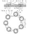
- the needle member 10 is inserted into the heart wall 93 shown in FIG. 5A from above (not shown in FIG. 5A and not in the direction of gravity: the same applies below), and the anchor pressing portion 13 provides one state-of-the-art anchor 30.
- the anchor 30 is discharged below the heart wall 93.
- the needle member 10 is pulled out above the heart wall 93, the hole through which the needle member 10 passes is naturally closed by the elasticity of the heart wall 93, and the most advanced anchor 30 is located below the heart wall 93. Left behind.
- the second anchor 30 is connected to the most advanced anchor 30 by a thread 35A having a length corresponding to the thickness of the heart wall 93. For this reason, the second anchor 30 is pulled out from the side hole 11 by the tension of the thread 35 ⁇ / b> A when the needle member 10 is removed, and is arranged on the upper surface of the heart wall 93. Then, as shown in FIG. 5B, the net 37 spreads in a disc shape on the upper surface of the heart wall 93. Since the thread 35B between the second anchor 30 and the third anchor 30 is sufficiently long, the needle member 10 can be operated in the same manner at the next arrangement position of the net 37. 5A and 5B will be described later in detail.
- the anchor pressing portion 13 extends to the joint portion with the manipulator 7 and can be moved in the distal direction via the manipulator 7.
- the controller 3 is provided with a needle member moving portion 3 ⁇ / b> B that moves the entire needle member 10 or the anchor pressing portion 13 via the manipulator 7. That is, the manipulator 7 has a known configuration that has a plurality of joints and can move the needle member 10 in various directions, front, rear, left, right, up and down.
- the manipulator 7 also includes a mechanism (for example, a well-known link mechanism) that moves the anchor pressing portion 13 in the distal direction.
- the needle member moving unit 3B can control the manipulator 7 to arbitrarily move the entire needle member 10 in various directions, and the anchor pressing unit 13 can be appropriately moved in the distal direction as necessary. Can be moved.
- data corresponding to the image photographed by the needle member camera 17 is sent to the controller 3 via a signal line (not shown) passing through the hollow portion of the housing 10B and the hollow portion or surface of the manipulator 7.
- a signal line (not shown) passing through the hollow portion of the housing 10B and the hollow portion or surface of the manipulator 7.
- the design accuracy of the manipulator 7 and the control accuracy of the needle member moving unit 3B are sufficient, it is easy to discharge the anchors 30 one by one as described above.
- a mechanical configuration as described in, for example, Japanese Patent Application Laid-Open No. 2012-165880 is added as necessary, and the anchor 30 is set to 1 The accuracy required for discharging one by one may be reduced.
- FIG. 2A is a schematic diagram showing the configuration of the forming head 20 in detail.
- the molding head 20 includes a molding camera 21, a nozzle 23, an X-ray irradiation unit 25, and a hook 27.
- the molding camera 21 captures the situation in front of the molding camera 21.
- the nozzle 23 discharges an X-ray curable component (an example of a curable substance).
- the X-ray irradiation unit 25 emits X-rays.
- the hook 27 locks the net 37 and the like.
- the molding camera 21 has a wide-angle lens at the tip, and can photograph a wide range in front of the nozzle 23.
- a wide-angle lens is also provided at the tip of the X-ray irradiation unit 25, and X-rays can be irradiated to a wide range in front of the nozzle 23.
- the X-ray curing component for example, well-known components described in JP-A-2001-46488 can be used.
- the molding camera 21 it is desirable to use a camera capable of photographing even in the near infrared region. Since the near-infrared ray is not easily absorbed by hemoglobin in blood, when the molding camera 21 can photograph the near-infrared region, the living tissue can be photographed better. Further, the molding camera 21 may be replaced with an imaging device using ultrasonic waves.
- the molding camera 21, the nozzle 23, the X-ray irradiation unit 25, and the hook 27 are connected to the main body 29 of the molding head 20 via joints 41, 43, 45, and 47, respectively.
- the joints 41, 43, 45, and 47 are configured using, for example, an elastic bellows or the like, and can direct the forming camera 21, the nozzle 23, the X-ray irradiation unit 25, and the hook 27 in any direction.
- the directions of the molding camera 21, the nozzle 23, the X-ray irradiation unit 25, and the hook 27 are configured to be adjustable from the manipulator 9 side.
- a wire with a bent tip is passed from the main body 29 through the hollow portions of the joints 41, 43, 45, 47 to the molding camera 21, the nozzle 23, the X-ray irradiation unit 25, and the hook 27.
- a threaded configuration can be employed.
- the inclination direction of each part can be adjusted by the rotation angle around the axis of the wire, and the inclination angle of each part can be adjusted by the insertion amount of the wire.
- various other mechanisms such as a mechanism employed for a guide wire of a catheter can be employed. If possible, a mechanism may be employed in which small electric actuators are inserted into the joints 41, 43, 45, and 47 and a drive signal is sent to them.
- the controller 3 is provided with a molding head moving part 3C.
- the molding head moving unit 3 ⁇ / b> C moves the entire molding head 20, the molding camera 21, the nozzle 23, the X-ray irradiation unit 25, or the hook 27 via the manipulator 9. That is, similarly to the manipulator 7, the manipulator 9 also has a known configuration that has a plurality of joints and can move the forming head 20 in various directions, front, rear, left, right, up and down.
- the manipulator 9 is also provided with a mechanism as described above that can bend the joints 41 to 47 freely.
- the forming head moving unit 3C controls the manipulator 9 to move the entire forming head 20, the forming camera 21, the nozzle 23, the X-ray irradiation unit 25, or the hook 27.
- the nozzle 23 is provided with an actuator using a piezoelectric element as used in a nozzle of an ink jet printer, for example.
- the controller 3 controls the discharge state of the X-ray curing component from the nozzle 23 by a drive signal sent to the nozzle 23 via a signal line (not shown) passing through the cavity portion of the main body 29 and the cavity portion or surface of the manipulator 9.
- the controller 3 controls the X-ray irradiation state from the X-ray irradiation unit 25 by the controller 3 by a drive signal sent via a signal line (not shown) passing through the cavity portion of the main body 29 and the cavity portion or surface of the manipulator 9.
- the Data corresponding to the image captured by the forming camera 21 is sent to the controller 3 via a signal line (not shown) passing through the hollow portion of the main body 29 and the hollow portion or surface of the manipulator 9.
- the X-ray curing component discharged from the nozzle 23 may be stored in the molding head 20 in advance, and is sent to the molding head 20 from the controller 3 or other in vitro equipment via an unillustrated ultrafine pipe. May be.
- the in-vivo insertion path forming tool 50 is configured in a cylindrical shape including a lower flange 51 and an upper flange 53.
- the lower flange 51 is inserted into the incision 91 of the skin 90 and engages with the inside of the skin 90.
- the upper flange 53 engages the outside of the skin 90.
- a sheet-like insertable portion 55 is attached to the upper surface (outer surface) of the in-vivo insertion path forming tool 50.
- the sheet-like insertable portion 55 is configured in a mesh shape through which the needle member 10 and the forming head 20 can be inserted and leakage of gas supplied into the body cavity can be suppressed.
- the in vivo insertion path forming tool 50 is made of an elastic material and can be inserted into the incision 91 in a crushed state.
- the configuration of the in-vivo insertion path forming tool 50 is disclosed in, for example, Japanese Patent Application Laid-Open No. 2012-196337, and will not be described in detail here. Further, when it is necessary to provide an incision in the heart wall 93 as in the operation for installing the artificial heart valve 99 described below, a similar in-vivo insertion path forming tool 50 is attached to the incision. Also good.
- FIG. 3 is a block diagram showing the configuration of the control system of the substitute manufacturing apparatus 1.
- the control unit 3A of the controller 3 is connected to the needle member moving unit 3B and the forming head moving unit 3C, and is connected to the needle member 10 and the forming head 20 via the manipulators 7 and 9 as described above. Control the behavior. Further, data corresponding to the captured image is input to the control unit 3A from the X-ray imaging apparatus 5, the needle member camera 17, and the molding camera 21. Further, the control unit 3 ⁇ / b> A drives the nozzle 23 and the X-ray irradiation unit 25 of the molding head 20.
- a database 3D that stores data such as the shape of the affected part of the patient.
- the database 3D may be built in the controller 3 or a hospital computer that stores a patient's medical record and the like.
- FIG. 4 is a flowchart showing the process of the control unit 3A when the artificial heart valve 99 is manufactured in vivo using the substitute manufacturing apparatus 1. This process is a process executed by a CPU (not shown) built in the control unit 3A based on a program stored in the ROM 3M built in the control unit 3A.
- the needle member 10 is controlled in S1 to S7 (S represents a step: the same applies hereinafter). Specifically, first, at S 1, the needle member 10 is displaced via the manipulator 7 based on the image taken by the X-ray imaging apparatus 5 or the needle member camera 17, and the needle member 10 is moved to the heart wall 93. Control to insert into the part is executed. In subsequent S ⁇ b> 3, one anchor 30 is discharged by moving the anchor pressing portion 13 via the manipulator 7, and then the needle member 10 is removed from the heart wall 93 via the manipulator 7.
- the process proceeds to S1 described above. As a result, the processes of S1 and S3 are repeated until the ejection of the anchor 30 is completed for all the required parts.
- the needle member 10 is inserted along the periphery of the heart valve annulus 95 of the patient (S1), and the anchor 30 is discharged (S3). ).
- the anchor 30 is discharged to the back side of the paper surface in FIG.
- the next anchor 30 is pulled out by the thread 35A as shown in FIG. 5A.
- the net 37 provided on the anchor 30 drawn out by the thread 35A spreads in a disk shape.
- the interval between the nets 37 is set in advance so that the X-ray curing component can be installed between the adjacent nets 37 according to the viscosity of the X-ray curing component. Is done.
- the required site is preset along the periphery of the heart valve annulus 95.
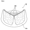
- the prosthetic heart valve 99 illustrated in FIG. 6 is used as the X-ray by using the net 37 installed as described above around the heart valve annulus 95 as a scaffold (ie, foundation or foundation).
- a process of forming with the curing component is performed. Specifically, first, in S11, based on the image captured by the X-ray imaging apparatus 5 or the molding camera 21, the molding head 20 is displaced via the manipulator 9, and the required portion where the X-ray curing component is to be discharged. The control for inserting the molding head 20 into is performed.
- the position of the net 37 installed as described above is confirmed based on the image taken by the molding camera 21.
- an X-ray curing component that has already been ejected may be used as a scaffold. In that case, the position of the X-ray hardening component is confirmed in S13.
- subsequent S15 based on the movement of the X-ray curing component or the net 37 photographed by the molding camera 21, the timing of the displacement is acquired. In so-called on-pump surgery where the heart is stopped and a heart-lung machine is used, the need for this step is relatively low. On the other hand, in the so-called off-pump operation in which the operation is performed without stopping the heart, there is a high need to acquire the timing at which the X-ray hardening component or the net 37 is displaced according to the pulsation.
- CAD data indicating the three-dimensional shape of the prosthetic heart valve 99 is read from the database 3D.
- the CAD data is created in advance by a doctor or the like according to the size of the patient's heart or the like.
- the positions of the nozzle 23 and the X-ray irradiation unit 25 are finely adjusted via the joints 43 and 45 in accordance with the timing of the displacement and the CAD data.
- the X-ray curing component is ejected from the nozzle 23 at a timing corresponding to the displacement timing, and the X-ray curing component is cured by the X-ray irradiation from the X-ray irradiation unit 25.
- known processes used in 3D printers can be applied.
- the hook 27 may be engaged with the heart wall 93 or the net 37 as necessary, and the positional relationship between them and the molding head 20 may be maintained.
- the term “curing” here does not necessarily mean that the X-ray curing component is cured as a rigid body, but it is desirable that the fluidity of the X-ray curing component is reduced so as to have appropriate elasticity.
- the intensity (irradiation reduction degree) of each part of the artificial heart valve 99 is changed by changing the irradiation intensity and irradiation time of the X-rays emitted from the X-ray irradiation unit 25 depending on the part of the artificial heart valve 99. May be different.
- subsequent S20 it is determined whether or not the molding of the prosthetic heart valve 99 is completed. If not completed (S20: N), the process proceeds to S11 described above. In this way, the processing of S11 to S20 is repeatedly executed. Then, the X-ray curable component is discharged and cured using the net 37 or the X-ray curable component that has already been discharged and cured as a scaffold (S19), whereby the artificial heart valve 99 is gradually formed. Then, when the molding of the artificial heart valve 99 is completed (S20: Y), the process is temporarily ended.
- the molding head 20 may be automatically removed.
- the removal of the forming head 20 may be performed by a doctor's hand in parallel with other treatment such as removal of the in-vivo insertion path forming tool 50.
- a highly functional prosthetic heart valve 99 as illustrated in FIG. 6 that is, the valve membrane 99B is stretched on the valve annulus 99A having a shape close to a biological valve
- the needle member 10 and the molding head 20 may be smaller than the artificial heart valve 99. For this reason, if the substitute manufacturing apparatus 1 of the present embodiment is used, the artificial heart valve 99 having the desired shape as described above can be molded by the low invasive surgery as described above.
- the substitute manufacturing apparatus 1 of the present embodiment when used, holes necessary for feeding and molding a curable substance (X-ray curable component) having fluidity into the living body are formed on the surface of the living body. Therefore, the invasiveness of the operation can be reduced.
- the substitute having such a size that cannot be put through the hole due to the curable material fed through the relatively small hole as described above. It can be molded in vivo and the replacement can be placed in the body.
- the process of FIG. 4 is not limited to the formation of an artificial heart valve, but can also be applied to the case of forming a tissue or an entire organ constituting a part of another organ.
- the process of FIG. 4 can also be applied to surgery for forming a ventricular septal replacement for a patient with ventricular septal defect.
- the needle member 10 and the molding head 20 may be attached to the distal end of the stomach camera.
- an artificial gastric wall as an example of an alternative can be formed at a location where a hole is formed in the stomach wall to close the hole.
- a substance that cures by reacting with stomach acid that is, hydrochloric acid
- examples of such substances include furan resins and phenol resins.
- the molding head 20 and the manipulator 9 that drives the molding head 20 can be applied to a surgery for molding a bone defect or a joint substitute in a patient's living body.
- the needle member 10 is not used.
- a head for driving the net 37 or the like into a patient's bone with a medical screw or staple may be attached to the manipulator 7 instead of the needle member 10.
- the molding camera 21, the nozzle 23, and the X-ray irradiation unit 25 are not necessarily provided in one molding head 20.
- the forming camera 21, the nozzle 23, and the X-ray irradiation unit 25 may be provided at the distal ends of different catheters, inserted from different blood vessels into the living body, and merged at the affected part. In that case, a less invasive surgery may be performed.
- control unit 3A may control the position of the nozzle 23 and the like by operating a catheter operation lever via an appropriate actuator.
- the position of the catheter is operated by a doctor, and the control unit 3A controls the positions of the forming camera 21, the nozzle 23, and the X-ray irradiation unit 25 via joints 41 to 47 provided at the distal end of the catheter. May be.
- the control unit 3A remotely controls the movement of the distal end with a strong magnetic force from the outside of the body to form the molding camera 21, the nozzle 23, and the X-ray irradiation unit 25. May be controlled.
- the curable substance is not limited to resin, elastomer, oligomer, prepolymer and the like, and various materials such as protein that coagulates under specific conditions are applicable.
- the X-ray curing component instead of the X-ray curing component, if a substance that cures at the patient's body temperature or a substance that cures by reacting with the patient's blood is used, the X-ray irradiation unit 25 can be omitted. Even when an X-ray curable component is used as the curable substance, the X-ray irradiation unit 25 can also be used by using the configuration of the X-ray imaging apparatus as in the alternative manufacturing apparatus of the second embodiment. Can be omitted.
- FIG. 7 is an explanatory diagram showing the arrangement of the X-ray irradiation unit / imaging unit in the substitute manufacturing apparatus of the second embodiment.
- an X-ray imaging apparatus including a set of a first X-ray irradiation unit 61 and a first X-ray imaging unit 62 around the patient 60, a second X-ray irradiation unit 63, and An X-ray imaging apparatus having a set with the second X-ray imaging unit 64 and an X-ray imaging apparatus having a set with the third X-ray irradiation unit 65 and the third X-ray imaging unit 66 are arranged at different angles.
- FIG. 7 is an explanatory diagram showing the arrangement of the X-ray irradiation unit / imaging unit in the substitute manufacturing apparatus of the second embodiment.
- an X-ray imaging apparatus including a set of a first X-ray irradiation unit 61 and a first X-ray imaging unit 62 around the patient 60, a
- the arrangement of each set is different about the vertical axis, but may be three-dimensionally different.
- the controller 3 is arranged near the patient 60, and the needle member 10 similar to that in the first embodiment and the molding head 20 in which the X-ray irradiation unit 25 in the first embodiment is omitted, It has been inserted into the body of the patient 60 as described above.
- FIG. 8 is a block diagram showing the configuration of the control system according to the substitute manufacturing apparatus of the second embodiment.
- the X-ray irradiation unit 25 and the X-ray imaging apparatus 5 are omitted. Instead, the first X-ray irradiation unit 61, the first X-ray imaging unit 62, and the second X-ray irradiation unit 63 are used.
- the second X-ray imaging unit 64, the third X-ray irradiation unit 65, and the third X-ray imaging unit 66 are different from the first embodiment in that they are connected to the control unit 3A.
- FIG. 9 is a flowchart showing processing executed in the control system. This process is a process executed by a CPU (not shown) built in the control unit 3A based on a program stored in the ROM 3M built in the control unit 3A. In FIG. 9, the same processing as that in the first embodiment shown in FIG. 4 is partially omitted, and different points will be described below.
- the irradiation mode is sequentially set in the first X-ray irradiation unit 61, the second X-ray irradiation unit 63, and the third X-ray irradiation unit 65 in S0.
- This sequential irradiation mode is sequentially applied to the first X-ray irradiation unit 61, the second X-ray irradiation unit 63, and the third X-ray irradiation unit 65 at an early cycle that does not cause a problem with respect to the treatment by the doctor and the image processing in the control unit 3A. In this mode, X-ray irradiation is performed.
- the doctor can recognize the surgical field and the control unit 3A can perform image processing, but the patient 60 is irradiated.
- the X-ray dose to be applied is an amount corresponding to any one of the X-ray irradiation units 61, 63, 65.
- the above-described processing after S1 is executed.
- the image data captured by the respective X-ray imaging units 62, 64, and 66 in accordance with the X-rays irradiated in the sequential irradiation mode are the X-rays in the first embodiment. It is used in place of data from the photographing device 5.
- S19A and S19B instead of S19, the following processing is performed.
- the position of the nozzle 23 is finely adjusted via the joint 43 in accordance with the displacement timing acquired in S15 (see FIG. 4) and the CAD data read out in S17, and according to the displacement timing.
- the X-ray curing component is discharged from the nozzle 23 (S19A).
- the above-described sequential irradiation mode is set again (S19B), and the process proceeds to the above-described S20.
- the X-ray curing component is not cured by X-rays irradiated from any one of the X-ray irradiation units 61, 63, 65, and the X-ray irradiation units 61,
- the sensitivity to X-rays is adjusted so that all of 63 and 65 are cured when X-rays are irradiated all at once.
- such adjustment is, for example, a mixture of an X-ray curing component, an X-ray fluorescence component that emits fluorescence upon receiving X-rays, and a photocuring component that is cured by light emitted from the X-ray fluorescence component.
- X-ray fluorescent component for example, a tungstate salt such as CaWO 4 can be used, and as the photocuring component, for example, polyvinyl cinnamate or the like can be used.
- the photocuring component for example, polyvinyl cinnamate or the like can be used.
- the first X-ray irradiation unit 61, the second X-ray irradiation unit 63, and the third X-ray irradiation unit 65 used for imaging of the affected part are cured as described above. Can also be used for. For this reason, in this embodiment, the effect similar to 1st Embodiment can be acquired, simplifying the structure of the shaping
- FIG. 1st Embodiment the effect similar to 1st Embodiment can be acquired, simplifying the structure of the shaping
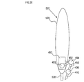
- the artificial heart valve 99 or the like may be molded using a molding bag 199 as illustrated in FIG.
- the molding bag 199 includes an annulus portion 199A having a hollow portion corresponding to the annulus 99A of the artificial heart valve 99 and a valve membrane portion 199B having a hollow portion corresponding to the valve membrane 99B.
- the shape is made of hard polyethylene or the like.
- the valve ring portion 199A and the valve membrane portion 199B of the molding bag 199 can be injected with an X-ray curable component from the cylindrical injection port 199C into the hollow portions.
- a perforation 199E formed thinly so as to be easily broken is formed on the outer periphery of the valve ring portion 199A.
- a nichrome wire as shown in a seventh embodiment to be described later may be provided so that the annulus portion 199A can be broken.
- the molding bag 199 is inserted into the patient's heart by a less invasive method using a catheter or the like in a small and contracted state. Thereafter, when an X-ray curable component is injected from the injection port 199C and X-rays are irradiated from outside the patient's body, the X-ray curable component is cured inside the annulus portion 199A and the valve membrane portion 199B. Can be molded inside the heart.
- the artificial heart valve 99 after molding can be taken out from the molding bag 199 by breaking the molding bag 199 with a perforation 199E.
- a constricted portion 199F having at least a small inner diameter is formed between the injection port 199C of the molding bag 199 and the valve ring portion 199A connected thereto.
- the molded artificial heart valve 99 is cut off at the constricted portion 199F and installed on the heart valve annulus 95.
- the operation of installing the molded artificial heart valve 99 on the heart valve annulus 95 of the patient may be performed using the needle member 10 or may be performed by a less invasive suture by a doctor.
- the substitute manufacturing apparatus of the third embodiment is an apparatus for irradiating X-rays from outside the patient's body to the molding bag 199 shown in FIG. 10 and the X-ray curable components injected into the molding bag 199 (
- it may be the apparatus shown in FIG.
- FIG. 11 is a schematic diagram showing the configuration of the forming head 200 of the substitute manufacturing apparatus of the fourth embodiment.
- the forming head 200 includes a cylindrical body 201 configured in a cylindrical shape.
- a plurality of nozzles 203 are formed on the front end surface 202 of the cylindrical body 201.
- a hollow support shaft 204 is held along the central axis of the cylinder 201.
- a laser beam irradiation unit 205 is connected to the tip of the support shaft 204 via a joint 215.
- the joint 215 is configured in the same manner as the joints 41, 43, 45, and 47 in the first embodiment. Therefore, for example, when the forming head 200 is attached to the manipulator 9 in the first embodiment, the laser beam irradiation unit 205 can be directed in a free direction via the forming head moving unit 3C. Further, the laser beam irradiation unit 205 can freely adjust the intensity of the laser beam irradiated from the laser beam irradiation unit 205.
- the nozzle 203 discharges a laser beam curing component and is configured to be able to adjust the discharge amount.
- a laser beam curing component for example, a general photo-curing resin that is a substance that can coexist with a living organism and has a molecular weight with appropriate fluidity and viscosity can be applied.
- this laser beam curing component may be accommodated in the molding head 200 in advance or sent from the outside, like the X-ray curing component in the first embodiment.
- the nozzle 203 various configurations such as a configuration using a piezoelectric element as in the nozzle 23 in the first embodiment can be applied.
- FIG. 12 is a block diagram showing a configuration of a control system when the molding head 200 is used by being attached to the manipulator 9.
- the X-ray imaging apparatus 5, the database 3D, and the forming head moving unit 3C are connected to the control unit 3A as in the first embodiment.
- the needle member moving unit 3B and the needle member camera 17 which are mechanisms related to the needle member 10 are not used.
- the control unit 3A controls the discharge amount of the laser beam curing component from the nozzle 203, and controls the irradiation intensity and irradiation direction of the laser beam from the laser beam irradiation unit 205.
- the manipulator 9 moves the molding head 200 in the direction of the tip surface 202 (hereinafter referred to as the insertion direction) or in the opposite direction (hereinafter referred to as the extraction direction), the manipulator 9
- the applied force (torque) is also input to the control unit 3A via the forming head moving unit 3C.
- FIG. 13 is a flowchart showing processing executed in the control system. As shown in FIG. 14A, this processing is performed on the outer surface 291 ⁇ / b> A of the blood vessel wall 291 of the living blood vessel 290 where the artificial blood vessel 299 is to be installed (on the opposite surface of the inner surface 291 ⁇ / b> B on the blood flow side). This is started after the work of bringing 202 into contact is performed. Further, the molding head 200 may be inserted into the living body via the in-vivo insertion path forming tool 50 described above, or in a state where the skin is incised so that the living blood vessel 290 is exposed.
- the operation of bringing the distal end surface 202 into contact with the outer surface 291A of the blood vessel wall 291 may be performed by a doctor operating the manipulator 9, and imaging of the X-ray imaging apparatus 5 with respect to the biological blood vessel 290 into which a contrast medium has been introduced. This may be done by automatically controlling the manipulator 9 based on the image. 13 is a process executed by a CPU (not shown) built in the control unit 3A based on a program stored in a ROM 3M that is also built in the control unit 3A.
- the processing is started, first, at S51, the forming head 200 is irradiated with laser light toward the blood vessel wall 291 with a relatively strong intensity to open a hole 292 (see FIG. 14B) in the blood vessel wall 291. Is inserted into the biological blood vessel 290. That is, the relatively strong strength is a strength that can at least partially destroy the tissue of the blood vessel wall 291.
- the relatively strong strength is a strength that can at least partially destroy the tissue of the blood vessel wall 291.
- S ⁇ b> 52 it is determined whether the forming head 200 has penetrated the blood vessel wall 291 based on a change in force in the insertion direction applied to the manipulator 9. If not penetrating (S52: N), the process proceeds to S51 and the above-described insertion process is repeatedly executed. When the forming head 200 penetrates the blood vessel wall 291 (S52: Y), the process proceeds to S53. .
- a predetermined amount of the laser light curing component set in advance is discharged from the nozzle 203 while the position of the molding head 200 with respect to the blood vessel wall 291 is fixed. Further, in S 53, a relatively weak laser beam is emitted from the laser beam irradiation unit 205 toward the periphery of the tip surface 202.
- the relatively weak strength means a strength that is suitable for curing the ejected laser beam curing component and that causes little damage to the blood vessel wall 291 (at least the hole does not penetrate the blood vessel wall 291). Then, the discharged laser beam curing component is cured.
- the engaging portion 295 that engages with the inner surface 291B of the blood vessel wall 291 is formed by the cured laser light curing component.
- a process of removing the forming head 200 from the blood vessel wall 291 while discharging the laser light curing component from the nozzle 203 is executed.
- the laser beam of relatively weak intensity is irradiated from the laser beam irradiation unit 205 toward the periphery of the tip surface 202.
- the discharged laser beam curing component is cured.
- the artificial blood vessel 299 is formed inside the hole 292 by the cured laser light curing component.
- subsequent S ⁇ b> 56 it is determined whether or not the forming head 200 has been removed from the blood vessel wall 291 based on a change in force in the extraction direction applied to the manipulator 9.
- a predetermined amount of a laser beam curing component set in advance is discharged from the nozzle 203 while the position of the forming head 200 with respect to the blood vessel wall 291 is fixed, and the laser beam from the laser beam irradiation unit 205 is used.
- the laser light curing component is cured.
- the engaging portion 295 that engages with the outer surface 291A of the blood vessel wall 291 is formed by the cured laser light curing component.
- the same processing as in S55 is performed. That is, while the laser beam curing component is ejected from the nozzle 203, the molding head 200 is moved in the direction of removal from the blood vessel wall 291, and at the same time, the ejected laser beam curing component is irradiated with the laser beam from the laser beam irradiation unit 205. Then, a process of curing the laser beam curing component is executed. Then, as shown in FIG. 14E, the artificial blood vessel 299 is formed outside the living blood vessel 290 by the hardened laser light curing component. In subsequent S59, it is determined whether or not the forming head 200 has been retracted to a preset stop position (may be outside the living body). If the stop has not reached the stop position (S59: N), the process of S58 is performed. Is repeatedly executed. When the artificial blood vessel 299 is formed up to the stop position by repeating this process (S59: Y), the process is temporarily terminated.
- a preset stop position may be outside the living body
- the substitute manufacturing apparatus of the present embodiment can easily form the bypass artificial blood vessel 299 for the biological blood vessel 290.
- the molded artificial blood vessel 299 is satisfactorily attached to the biological blood vessel 290 by the engaging portions 295 formed on the inner surface 291B and the outer surface 291A of the blood vessel wall 291, respectively.
- the nozzle 203 is also formed inside the cylinder 201, and the angle of the laser beam irradiation unit 205 and the laser beam irradiation timing with respect to the laser beam curing component discharged from the nozzle 203 are set. It may be controlled by applying the technique of stereolithography. In that case, a valve etc. can also be shape
- a pressure sensitive element is provided on the outer periphery of the distal end portion of the cylindrical body 201, it is determined whether or not the blood vessel wall 291 in S52 and S56 is penetrated based on the detection signal of the pressure sensitive element. Good.
- FIGS. 15A to 15C are schematic views showing the configuration of the needle member 310 used in the substitute manufacturing apparatus of the fifth embodiment.
- the needle member 310 in the present embodiment is configured in many parts in the same manner as the needle member 10 in the first embodiment. Therefore, the portions of the needle member 310 that are configured in the same manner as the needle member 10 are denoted by the same reference numerals used in FIG. 2B in FIGS. 15A to 15C, and detailed description of the configuration is omitted.
- the difference between the needle member 310 and the needle member 10 will be mainly described.
- FIG. 15A schematically shows a cross section along the axial direction (insertion / extraction direction) of the needle member 310.
- the anchor pressing portion 13 is configured to have a slightly smaller diameter than the needle member 10.
- a thread supply part 319 and a nozzle 323 are provided on the inner peripheral surface of the casing 310B surrounding the anchor pressing part 13 in a cylindrical shape on the inner peripheral surface on the side where the side holes 11 are formed. It has been.
- FIG. 15B schematically shows a cross section taken along line XVB-XVB of FIG. 15A.
- the nozzle 323 and the yarn supply unit 319 are provided adjacent to each other.
- the yarn supply unit 319 forcibly feeds the yarn 35.
- the yarn 35 fed out from the yarn supply unit 319 is connected to the anchor 30 on the most proximal side.
- the thread 35 between the anchor 30 at the most proximal end, that is, the anchor 30 finally discharged from the side hole 11, and the thread supply unit 319 may be referred to as a thread 35C.
- a mechanism such as an actuator for feeding the yarn 35C from the yarn supply unit 319 may be provided in the yarn supply unit 319 or outside the living body into which the needle member 310 is inserted. .
- the nozzle 323 heats and imparts the fluidity of a thermoplastic resin 395 (see FIG. 18) that can coexist with organisms to the yarn 35C that is fed from the yarn supply unit 319, and adheres the yarn to the yarn 35C.
- FIG. 15C is a schematic view partially showing a state in which the needle member 310 is viewed from the side hole 11 side.
- a V-shaped cut 11 ⁇ / b> A is formed in the center of the end edge of the side hole 11 on the tip 310 ⁇ / b> A side.
- This cut 11A extends to the vicinity of the front end 310A of the housing 310B.
- a heater 325 is provided at the tip of the cut 11A.
- the thread 35C fed from the thread supply unit 319 is guided by the notch 11A and hits the heater 325 when at least the needle member 310 is moved in the proximal direction (that is, the direction opposite to the distal end part 310A). Touch.
- the resin 395 discharged from the nozzle 323 and attached to the yarn 35C is heated by the heater 325. Then, the heated resin 395 is easily integrated with the resin 395 already discharged into the living body, and the resin 395 is cured by the temperature of the resin 395 decreasing in the living body.
- the needle member camera 17 is provided on the side surface of the casing 310B on the side where the side holes 11 are provided. Therefore, the needle member camera 17 can satisfactorily photograph the behavior of the thread 35C guided by the notch 11A and the behavior of the resin 395 heated by the heater 325.
- FIG. 16 is a block diagram showing the configuration of a control system of an alternative manufacturing apparatus as a fifth embodiment in which this needle member 310 is used by being attached to the manipulator 7 instead of the needle member 10.
- the X-ray imaging apparatus 5, the database 3D, and the needle member moving unit 3B are connected to the control unit 3A as in the first embodiment.
- the control unit 3A controls the amount of resin 395 discharged from the nozzle 323, controls the amount of yarn 35C supplied from the yarn supply unit 319, controls on / off of the heater 325, and controls the needle member Data corresponding to the image captured by the camera 17 is input.
- the block diagram of FIG. 16 and the flowchart of FIG. 17 are illustrated on the assumption that the molding head moving unit 3C, which is a mechanism related to the molding head 20, is not used.
- a mechanism related to the manipulator 9 may be used in combination.
- FIG. 17 is a flowchart showing processing executed in the control system.
- This process is a process executed by a CPU (not shown) built in the control unit 3A based on a program stored in the ROM 3M built in the control unit 3A.
- This process includes the same process as the process in the first embodiment shown in FIG. Therefore, the same processes as those in the first embodiment are denoted by the same reference numerals used in FIG. 4 and the detailed description of the configuration is omitted.
- the difference between the process in FIG. 17 and the process in FIG. 4 will be mainly described.
- the process of S7 is omitted.
- the substitute formed by the processing in the present embodiment may be the artificial heart valve 99 similar to that formed in the first embodiment, the stent 397 shown in FIG. May be an alternative.
- the needle member 310 is moved to a required site based on the images taken by the X-ray imaging apparatus 5 and the needle member camera 17.
- the position of the thread 35 (thread 35 ⁇ / b> B or thread 35 ⁇ / b> C) extending from the anchor 30 or the resin 395 that has already been discharged is confirmed based on the captured image of the needle member camera 17.
- S15C instead of S15, based on the movement of the resin 395 or the thread 35 photographed by the needle member camera 17, the timing of their displacement is acquired.
- the CAD data is read out as in the first embodiment.
- the yarn 35 ⁇ / b> C is discharged together with the resin 395 through the yarn supply unit 319 according to the displacement timing and CAD data.
- the needle member 310 may be moved so that the thread 35C is discharged more smoothly.
- the resin 395 is attached from the nozzle 323 over the entire length of the yarn 35C fed from the yarn supply unit 319, and the heater 325 is always operated while the yarn 35C is fed. Assume that it is turned on.
- a step of switching discharge / non-discharge of resin from the nozzle 323 and a step of switching on / off of the heater 325 may be added as necessary.
- FIG. 17 can be applied to molding various alternatives such as the artificial heart valve 99.
- the process of FIG. 17 will be described focusing on an example in which a stent 397 as an example of an alternative to the cerebral artery 390 is formed at a place where the aneurysm 392 of the cerebral artery 390 is formed.
- the anchor 30 only needs to prepare a pair of anchors 30 with the other surface 32 facing each other, and the net 37 can be omitted.
- the length of the thread 35 ⁇ / b> A disposed between the other surfaces 32 of the pair of anchors 30 is set slightly shorter than the thickness of the blood vessel wall 391 at the portion of the aneurysm 392.
- the needle member 310 is inserted into the required site Y along the arrow Z passing through the cerebral artery 390, as illustrated in FIG.
- Such an operation on the needle member 310 may be performed by attaching the needle member 310 to the distal end of a catheter (not shown) and operating the operation lever of the taper by the manipulator 7 or other actuator.
- the needle member 310 is inserted through the inside of the cerebral artery 390 to the vicinity of the aneurysm 392 (for example, a position where a part of the distal end portion 310A opposes a part of the aneurysm 392) among the operations on the catheter.
- the operation may be performed by a doctor, and the subsequent operation may be performed via the manipulator 7 or other actuator.
- the control unit 3A may remotely control the movement of the needle member 310 from outside the body with a strong magnetic force.
- a remote control mechanism using magnetic force is detailed in, for example, US Pat. Nos. 6,630,879 and 6,157,853, and will not be described in detail here.
- the needle member 310 may be inserted up to the vicinity of the aneurysm 392 by a doctor's catheter operation.
- the anchor 30 is discharged to the outside of the aneurysm 392, and the needle member 310 is extracted to the inside of the aneurysm 392.
- the pair of anchors 30 is fixed to the aneurysm 392 with the blood vessel wall 391 interposed therebetween as shown in FIG.
- the thread 35 ⁇ / b> C extending from the anchor 30 inside the aneurysm 392 is connected to the needle member 310.
- an affirmative determination is made in S5 from the time when the process first moves to this step.
- the thread 35C is discharged so that the inside of the aneurysm 392 is filled with the resin 395. At this time, there may be a slight gap 396 in which neither the resin 395 nor the thread 35C exists inside the aneurysm 392. That is, it is only necessary that the shape of the aneurysm 392 can be maintained by the resin 395 filled in the aneurysm 392.
- the thread 35C is formed along the inner peripheral surface of the cerebral artery 390 adjacent to the aneurysm 392 from upstream and downstream in the blood flow direction.
- the needle member 310 may be automatically removed. It may be done by a doctor. Further, the yarn 35 ⁇ / b> C after completion of molding may be burned out by the heater 325.
- the resin 395 that fills the aneurysm 392 and maintains the shape of the aneurysm 392 and the stent 397 (both are substitutes for the cerebral artery 390). Can be easily formed.
- a resin layer 399 may also be formed outside the aneurysm 392.
- the molding head 20 of the substitute manufacturing apparatus 1 of the first embodiment is inserted to the outside of the aneurysm 392 through such a less invasive surgery, and the molding head 20 is driven. It may be formed by.
- thermoplastic resin is used as the resin 395, but another curable substance may be used as the resin 395.
- a thermosetting resin that cures at a relatively low temperature of about 50 ° may be used.
- the heater 325 heats the thermosetting resin, so that the thermosetting resin is cured.
- the X-ray curing component used in the first embodiment or the like may be used instead of the resin 395.
- the heater 325 is replaced with the X-ray irradiation unit, so that the laser beam curing component facing the laser beam irradiation unit can be cured.
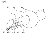
- FIG. 19 is a perspective view schematically showing the configuration of the needle member 410 used in the substitute manufacturing apparatus of the sixth embodiment.
- the needle member 410 has an outer diameter similar to that of the needle members 10 and 310, but does not include the anchor 30, and includes a nozzle 411, a photographing hole 412 and an irradiation hole 413 at the tip.
- the nozzle 411 is connected to an X-ray curable component supply unit 416 built in the needle member 410.
- the nozzle 411 discharges the X-ray curable component supplied from the X-ray curable component supply unit 416 in an amount corresponding to the control signal.
- the X-ray curing component is the same as that used in the first embodiment.
- the imaging hole 412 is connected to a needle member camera 417 built in the needle member 410.
- the needle member camera 417 photographs the situation in front of the photographing hole 412.
- the irradiation hole 413 is connected to an X-ray irradiation unit 418 built in the needle member 410. From the irradiation hole 413, the X-rays irradiated from the X-ray irradiation unit 418 are irradiated toward the outside of the needle member 410.
- the X-ray curing component discharged from the nozzle 411 can be cured by the X-ray irradiated from the irradiation hole 413.
- the camera 417 for needle members can image
- the needle member 410 configured as described above is supported by a columnar support member 450 via a joint 430 configured similarly to the joints 41, 43, 45, and 47 in the first embodiment.
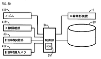
- FIG. 20 is a block diagram showing a configuration of a control system of an alternative manufacturing apparatus as a sixth embodiment in which the needle member 410 is used by being attached to the manipulator 7.
- the X-ray imaging apparatus 5, the database 3D, and the needle member moving unit 3B are connected to the control unit 3A, as in the first embodiment.
- the forming head moving unit 3 ⁇ / b> C that is a mechanism related to the forming head 20 may not be used.
- the needle member moving unit 3B is configured to be able to control the joint 430 in the same manner as the forming head moving unit 3C in the first embodiment.
- control unit 3A controls the discharge amount of the X-ray curing component from the nozzle 411, controls the X-ray irradiation state from the X-ray irradiation unit 418, and corresponds to the image captured by the needle member camera 417. Input data.
- FIG. 21 is a flowchart showing processing executed in the control system. This process is a process executed by a CPU (not shown) built in the control unit 3A based on a program stored in the ROM 3M built in the control unit 3A. Moreover, the substitute manufacturing apparatus of this embodiment is suitable for the case where the substitute is formed at a site where the flow of body fluid such as blood is less than that in the blood vessel.
- the needle member 410 is inserted into a required site in the vicinity of the affected area, as in S1 in each of the above embodiments.
- photographing with the needle member camera 417 is performed.
- the CAD data of the alternative is read out in the same manner as in S17 in each of the above embodiments, and in S54, the X-ray curing component is discharged and cured. That is, in S54, based on the data of the image photographed in S52 and the CAD data read out in S53, the nozzle 411 is connected via the joint 430 so that a desired substitute is formed at a required portion. The position (that is, the position of the needle member 410) is finely adjusted.
- an X-ray curing component in an amount corresponding to the data is discharged from the nozzle 411 after position adjustment, and the X-ray curing component is cured by the X-rays irradiated from the irradiation hole 413.
- S55 it is determined whether or not the molding of the substitute has been completed. If it has not been completed (S55: N), the process proceeds to S57.
- S57 the needle member 410 is moved to mold the remaining portion of the substitute, and the process proceeds to S52 described above.
- the control unit 3A drives the manipulator 7 and the joint 430 via the needle member moving unit 3B, so that the needle member 410 is moved. In this way, the processing of S52 to S57 is repeatedly executed, and when the molding of the substitute is completed (S55: Y), the processing is once ended.
- FIG. 22 is an explanatory diagram showing an example in which a plate 470 as an example of an alternative to bone B is formed at a location where a crack C is formed on bone B.
- a plate 470 is molded, a cut is made so that the tip of the needle member 410 passes through the surface of the skin, and the needle member 410 is inserted from the cut to the surface of the bone B (S51). Then, by repeatedly executing the processing of S52 to S57 using the shape data of the plate 470 as the CAD data, the plate 470 formed by hardening the X-ray hardening component is formed on the surface of the bone B.
- grains for example, porous sintered compact
- porous sintered compact such as a calcium phosphate and a calcium titanate
- these materials are familiar with bone B and promote the integration of plate 470 with bone B.
- a porous sintered body made of calcium phosphate such as hydroxyapatite is included as a filler in the X-ray curable component, bone regeneration begins in the porous sintered body, and the plate 470 and the bone B are further integrated. Promoted well.
- the plate 470 may be formed after an adhesive layer is formed on the surface of the bone B.
- a lump may be formed by an X-ray hardening component containing metal particles such as titanium as a filler at a site in contact with nerves in muscle by the same method. In that case, the same effect as that when the wrinkle is continuously applied to the part may be obtained.
- FIG. 23 shows an example of molding a member (that is, a substitute for the epiglottis) that assists the person H suffering from dysphagia to discharge sputum or the like.
- a tracheal cannula 480 is attached between the throat I of the person H and the trachea K.
- an opening 481 on one end side communicates with the outside air from the front surface of the person H, and the other end bends downward and communicates with the trachea K.
- the capillary 484 can be formed between the opening 481 of the tracheal cannula 480 and the inner wall surface of the trachea K.
- the needle member 410 is inserted from the opening 481 to the trachea K (S51).
- the needle member 410 is rotated slightly in a spiral manner to form the capillary 484 (S52 to S54). That is, the capillary tube 484 is formed by repeatedly executing the processing of S52 to S57 using the shape data of the capillary tube 484 as the CAD data.
- the capillary tube 484 may be formed by forming jagged edges (that is, serrated irregularities) on the outer periphery of the opening of the nozzle 411. In that case, a groove that causes capillary action is formed on the surface of the X-ray curable component discharged from the nozzle 411 due to the unevenness of the jaggedness. For this reason, the X-ray hardening component discharged from the nozzle 411 becomes the capillary 484 only by being hardened as it is. Therefore, in this case, the processing becomes easier.
- jagged edges that is, serrated irregularities
- the needle member 410 can be passed through the outer peripheral surface 482. If the outer peripheral surface 482 is made of an elastic material or the like, after the needle member 410 is removed, the hole through which the needle member 410 has passed is closed by an elastic restoring force.
- an elastic material for example, the sheet-like insertable portion 55 used in the surgery according to the first embodiment may be used.
- a filter 485 that suppresses saliva and the like from dropping into the trachea K can be formed above the tracheal cannula 480 as shown in FIG.
- the needle member 410 is inserted through the outer peripheral surface 482 to the upper side of the tracheal cannula 480 in the process of S51, and the filter 485 is formed in the processes of S52 to S57. That is, the filter 485 is formed by executing the processing of S52 to S57 using the shape data of the filter 485 as the CAD data.
- a capillary for sending saliva or the like adhering to the filter 485 to the esophagus S may also be formed.
- the cut-in portion is a vocal cord. Instead of this, it may be configured to generate air vibration. As such a configuration, a known configuration used for a toy that makes a sound such as a whistle can be applied.
- a controller 490 as illustrated in FIG. 24 may be used instead of the above-described controller 3 installed on the floor or the like of the operating room.
- FIG. 24 is a schematic diagram showing a configuration of an alternative manufacturing apparatus as a modification of the sixth embodiment.
- the controller 490 includes the control unit 3A and the needle member moving unit 3B described above (not shown in FIG. 24).
- a frame 486 is provided outside the body of the tracheal cannula 480 as is well known, and the controller 490 is supported by a pedestal 491 connected to the frame 486.
- One end of an arm 492 is connected to the controller 490 via a joint 493, and the other end of the arm 492 is connected to the support member 450 via a joint 494.
- the joints 493, 494 are configured in the same manner as the joints 41, 43, 45, 47 in the first embodiment.
- the movable range of the joints 480, 493, 494 and the length of the arm 492 are designed so that the capillary 484 and the filter 485 can be formed by the needle member 410.
- the control unit 3A built in the controller 490 executes the processing of FIG. 21, whereby the capillary 484 and the filter 485 as shown in FIG. 23 can be formed.
- the person H can form the capillary tube 484 and the filter 485 while walking outdoors.
- a string-like portion for pulling out the filter 485 to the outside of the body may be formed on the filter 485 by the needle member 410.
- the person H can pick up the filter 485 whose performance has been lowered and pull it out from the opening portion 481 to cause the needle member 410 to reshape the filter 485.
- X-rays for curing the X-ray curing component discharged from the nozzle 411 are irradiated from outside the body. Also good.
- the configuration from the controller 490 to the needle member 410 shown in FIG. 24 can be further miniaturized.
- the X-ray curing component may be supplied from a tank or the like provided in the controller 490.
- the laser beam curing component used in the fourth embodiment may be used instead of the X-ray curing component.
- the X-ray irradiation unit 418 is replaced with a laser beam irradiation unit, and the laser beam irradiated from the laser beam irradiation unit is irradiated from the irradiation hole 413.
- the configuration from the controller 490 to the needle member 410 is formed in a hollow portion away from the scalp on the inner surface of the cap 499 such as a top hat as in the alternative manufacturing apparatus as another modified example illustrated in FIG. It may be provided.
- the person H while the person H is wearing the hat 499, the person H can be shaped with hair. That is, the hair is formed by executing the process of FIG. 21 using the hair shape data as the CAD data.
- the needle member 410 may form a pedestal that simulates the hair root into a pore in the head of the person H.
- IPS cells artificial pluripotent stem cells
- the configuration from the controller 490 to the needle member 410 is the same as that of another alternative manufacturing apparatus illustrated in FIG. May be provided at the end of the grip portion 520 on the provided side.
- an alternative for example, stomach wall in the case of stomach surgery
- an alternative that closes a hole or the like opened in the affected part
- the substitute can be formed.
- the process of FIG. 21 using the shape data of the substitute such as the stomach wall as the CAD data is executed.
- a stomach wall is shape
- control unit 3A is an example of the control unit
- database 3D is an example of the storage unit
- the nozzles 23, 203, 323, 411, or the molding bag 199 is an example of the feeding unit
- the X-ray irradiation is an example of the heating unit
- the parts 25, 61, 63, 65, 418 or the laser beam irradiation part 205 or the heater 325 correspond to an example of an alternative molding part, respectively.
- the substitute molding unit of the present invention is the heater 325.
- the molding may be performed by adjusting the position where the fluidity of the curable substance is reduced.
- the substitute molding part may be constituted by a hook whose position can be controlled.
- the substitute manufacturing apparatus 1 according to the first embodiment will be described.
- the substance that cures at the patient's body temperature and the substance that cures by reacting with the patient's blood described in the modification of the substitute production apparatus 1 Any substance that cures by reacting with gastric acid (that is, hydrochloric acid) corresponds to a curable substance whose fluidity is reduced in the living body after being sent into the living body.
- gastric acid that is, hydrochloric acid
- the nozzle 23 corresponds to an example of the feeding portion
- the nozzle 23, the joint 43, and the manipulator 9 adjust the position where the fluidity of the curable substance fed by the feeding portion is reduced to adjust the living tissue.
- the present invention is not limited to the above embodiments, and can be implemented in various forms without departing from the gist of the present invention.
- part or all of the processing in each of the embodiments may be performed by a doctor's operation.
- the curable substance is not limited to the X-ray curable component and the laser beam curable component described above, but other than X-rays such as a material curable by other electromagnetic waves such as infrared rays, visible rays, ultraviolet rays, and microwaves, and neutron rays.
- Substances that are cured by radiation, substances that are cured by ultrasonic waves, and proteins that coagulate under specific conditions can also be used.
- the data of the three-dimensional shape of the substitute is not necessarily required, and at least a part of the feeding portion (molding bag 199, cylindrical body 201) as in the third and fourth embodiments described above. May constitute a mold for molding the substitute.
- the above-described needle members 10, 310, 410, forming heads 20, 200, etc. are made using a shape memory alloy having a shape as illustrated by the body temperature, the size can be further reduced when inserted into the living body. There is a case. In that case, the needle members 10, 310, 410, the molding heads 20, 200, etc. described above may be more easily inserted into the living body.
- the present invention can also be applied to surgery for transplanting an organ produced from iPS cells or other organs into a living body.
- a bag that spreads in the living body and becomes a culture device such as a petri dish like the molding bag 199 is inserted into the living body using a catheter or the like, and immature iPS cells and culture solution are inserted into the culture device. May be injected using a catheter or the like.
- a culture apparatus 600 as an alternative manufacturing apparatus of the seventh embodiment illustrated in FIG. 27 includes a hollow spherical culture chamber 620 at the tip of a tube 610 into which iPS cells can be inserted.
- the tube 610 and the culture chamber 620 are integrally formed of a thermoplastic resin, and a nichrome wire 630 for cutting them (particularly the culture chamber 620) is provided in the longitudinal direction of the tube 610 and the outer periphery of the culture chamber 620. It has been.
- the culture device 600 When such a culture device 600 is inserted into a living body using a catheter or the like and the opening 611 of the tube 610 is exposed to the outside of the body, the culture device 600 is cultured with immature IPS cells via the opening 611. A liquid or the like can be injected. Thereafter, if necessary, microwaves are irradiated from outside the body, or activins having appropriate concentrations are sequentially injected to differentiate iPS cells, whereby the iPS cells can be made into a mature organ.
- Such an organ can be removed from the culture chamber 620 by cutting the culture chamber 620 by energizing the nichrome wire 630 and connected to other living organs by minimally invasive surgery.
- a catheter, a tube 610 and the like for injecting IPS cells correspond to the feeding part
- a culture chamber 620 inserted into the living body and a microwave irradiation part correspond to the substitute molding part.
- the culture chamber 620 may be made of a material through which body fluid can permeate.
- the above-mentioned needle member 10 or 310 or 410, the molding head 20 or 200, the molding bag 199, etc. also uses a catheter in the blood vessel from the base of the foot, etc., as in the above-described IPS cells. It may be inserted. In that case, substitutes such as the artificial heart valve 99 and the artificial blood vessel 299 can be formed in the living body by a less invasive operation.
Landscapes
- Health & Medical Sciences (AREA)
- Surgery (AREA)
- Life Sciences & Earth Sciences (AREA)
- Molecular Biology (AREA)
- General Health & Medical Sciences (AREA)
- Veterinary Medicine (AREA)
- Engineering & Computer Science (AREA)
- Biomedical Technology (AREA)
- Heart & Thoracic Surgery (AREA)
- Medical Informatics (AREA)
- Public Health (AREA)
- Animal Behavior & Ethology (AREA)
- Nuclear Medicine, Radiotherapy & Molecular Imaging (AREA)
- Orthopedic Medicine & Surgery (AREA)
- Reproductive Health (AREA)
- Vascular Medicine (AREA)
- Neurology (AREA)
- Neurosurgery (AREA)
- Rheumatology (AREA)
- Prostheses (AREA)
Abstract
L'invention concerne un dispositif de production d'un remplacement de tissu vivant, qui comprend : une unité de distribution qui est introduite dans un corps vivant et distribue une matière durcissable apte à s'écouler dans le corps vivant ; et une unité de façonnage de remplacement qui amène l'aptitude à l'écoulement de la matière durcissable, qui a été distribuée par l'unité de distribution, à être réduite à l'intérieur du corps vivant de façon à façonner un remplacement de tissu vivant.
Priority Applications (1)
| Application Number | Priority Date | Filing Date | Title |
|---|---|---|---|
| JP2014556452A JPWO2014109391A1 (ja) | 2013-01-11 | 2014-01-10 | 生体組織の代替物製造装置 |
Applications Claiming Priority (2)
| Application Number | Priority Date | Filing Date | Title |
|---|---|---|---|
| JP2013-003752 | 2013-01-11 | ||
| JP2013003752 | 2013-01-11 |
Publications (1)
| Publication Number | Publication Date |
|---|---|
| WO2014109391A1 true WO2014109391A1 (fr) | 2014-07-17 |
Family
ID=51167037
Family Applications (1)
| Application Number | Title | Priority Date | Filing Date |
|---|---|---|---|
| PCT/JP2014/050340 Ceased WO2014109391A1 (fr) | 2013-01-11 | 2014-01-10 | Dispositif de production de remplacement de tissu vivant |
Country Status (2)
| Country | Link |
|---|---|
| JP (1) | JPWO2014109391A1 (fr) |
| WO (1) | WO2014109391A1 (fr) |
Cited By (4)
| Publication number | Priority date | Publication date | Assignee | Title |
|---|---|---|---|---|
| EP3219262A1 (fr) * | 2016-03-18 | 2017-09-20 | Invamed Saglik Ilac Sanayi Ve Ticaret A.S. | Système et dispositif d'embolisation robotique |
| CN112423712A (zh) * | 2018-04-10 | 2021-02-26 | 卡内基梅隆大学 | 通过自由可逆嵌入对医疗设备进行3d生物打印 |
| JP2022506800A (ja) * | 2018-11-06 | 2022-01-17 | キャプスラケアー エルエルシー | 身体器官または腫瘤を包むためのカプセル器具およびその使用 |
| US12409602B2 (en) | 2019-10-18 | 2025-09-09 | Carnegie Mellon University | Modification of rheology and machine pathing for improved 3D printing of soft materials |
Citations (5)
| Publication number | Priority date | Publication date | Assignee | Title |
|---|---|---|---|---|
| JPH10507097A (ja) * | 1994-07-18 | 1998-07-14 | ピーター シー. ブロック, | 経管腔移植可能な膨張性補綴心臓血管弁 |
| JP2007536003A (ja) * | 2004-05-05 | 2007-12-13 | ダイレクト フロウ メディカル、 インク. | 現場形成支持構造を備えたステントレス心臓弁 |
| JP2008126459A (ja) * | 2006-11-20 | 2008-06-05 | Kanagawa Acad Of Sci & Technol | ゲルの製造方法及びそのための装置 |
| US20080281335A1 (en) * | 2005-11-09 | 2008-11-13 | Fell Barry M | System and Method For Shaping an Anatomical Component |
| WO2011119220A1 (fr) * | 2010-03-23 | 2011-09-29 | Boston Scientific Scimed, Inc. | Dispositif d'annuloplastie |
-
2014
- 2014-01-10 WO PCT/JP2014/050340 patent/WO2014109391A1/fr not_active Ceased
- 2014-01-10 JP JP2014556452A patent/JPWO2014109391A1/ja active Pending
Patent Citations (5)
| Publication number | Priority date | Publication date | Assignee | Title |
|---|---|---|---|---|
| JPH10507097A (ja) * | 1994-07-18 | 1998-07-14 | ピーター シー. ブロック, | 経管腔移植可能な膨張性補綴心臓血管弁 |
| JP2007536003A (ja) * | 2004-05-05 | 2007-12-13 | ダイレクト フロウ メディカル、 インク. | 現場形成支持構造を備えたステントレス心臓弁 |
| US20080281335A1 (en) * | 2005-11-09 | 2008-11-13 | Fell Barry M | System and Method For Shaping an Anatomical Component |
| JP2008126459A (ja) * | 2006-11-20 | 2008-06-05 | Kanagawa Acad Of Sci & Technol | ゲルの製造方法及びそのための装置 |
| WO2011119220A1 (fr) * | 2010-03-23 | 2011-09-29 | Boston Scientific Scimed, Inc. | Dispositif d'annuloplastie |
Non-Patent Citations (1)
| Title |
|---|
| CHAO JIN: "Injectable 3-D Fabrication of Medica Electronics at the Target Biological Tissues", SCIENTIFIC REPORTS, 6 December 2013 (2013-12-06) * |
Cited By (7)
| Publication number | Priority date | Publication date | Assignee | Title |
|---|---|---|---|---|
| EP3219262A1 (fr) * | 2016-03-18 | 2017-09-20 | Invamed Saglik Ilac Sanayi Ve Ticaret A.S. | Système et dispositif d'embolisation robotique |
| CN112423712A (zh) * | 2018-04-10 | 2021-02-26 | 卡内基梅隆大学 | 通过自由可逆嵌入对医疗设备进行3d生物打印 |
| JP2021512742A (ja) * | 2018-04-10 | 2021-05-20 | カーネギー−メロン ユニバーシティCarnegie−Mellon University | 自由形状可逆的埋め込みを通した3dバイオプリンティング医療装置 |
| JP7076848B2 (ja) | 2018-04-10 | 2022-05-30 | カーネギー-メロン ユニバーシティ | 自由形状可逆的埋め込みを通した3dバイオプリンティング医療装置 |
| JP2022506800A (ja) * | 2018-11-06 | 2022-01-17 | キャプスラケアー エルエルシー | 身体器官または腫瘤を包むためのカプセル器具およびその使用 |
| JP7470331B2 (ja) | 2018-11-06 | 2024-04-18 | キャプスラケアー エルエルシー | 身体器官または腫瘤を包むためのカプセル器具およびその使用 |
| US12409602B2 (en) | 2019-10-18 | 2025-09-09 | Carnegie Mellon University | Modification of rheology and machine pathing for improved 3D printing of soft materials |
Also Published As
| Publication number | Publication date |
|---|---|
| JPWO2014109391A1 (ja) | 2017-01-19 |
Similar Documents
| Publication | Publication Date | Title |
|---|---|---|
| US20240156492A1 (en) | Three dimensional robotic bioprinter | |
| US20230404550A1 (en) | Apparatus and method to seal a tissue tract | |
| EP1337183B1 (fr) | Sonde a ultrasons dotee d'un systeme de positionnement destine a des dispositifs d'exploration et d'intervention | |
| JP5595905B2 (ja) | 耳内のターゲット組織の同時両側治療システム及び方法 | |
| US20100010520A1 (en) | Tissue fastener | |
| US20130041265A1 (en) | Methods and apparatus for introducing cells at a tissue site | |
| TWI639417B (zh) | 用於治療聲門閉合不全之方法及裝置 | |
| JPWO2014109391A1 (ja) | 生体組織の代替物製造装置 | |
| US12004707B2 (en) | Airway visualization system | |
| WO2019157319A1 (fr) | Dispositifs et procédés pour administrer une matière dans un tissu biologique ou une cellule | |
| KR20180122653A (ko) | 곡침을 통해 치료제를 망막하 투여하기 위한 장치 | |
| CN1787785A (zh) | 用于可植入性医疗装置的可固化介质 | |
| KR20180027540A (ko) | 척추 수술을 위한 향상된 경막외 접근을 위한 경피적 시스템 및 방법 | |
| JP2012515603A (ja) | インプラント送達の方法とシステム | |
| CN112423712A (zh) | 通过自由可逆嵌入对医疗设备进行3d生物打印 | |
| TWI731716B (zh) | 定位導引裝置 | |
| DE112019005588T5 (de) | Außenskelett zur Unterstützung chirurgischer Positionierung, Verfahren zur Herstellung des Außenskeletts und ein chirurgisches Verfahren zur Anwendung eines solchen Außenskeletts | |
| CN111529966A (zh) | 一种可移除式人体放射治疗定位金标植入装置 | |
| TWI747316B (zh) | 液狀藥劑滲透裝置之輔助裝置、液狀藥劑滲透系統及其運作方法、以及內視鏡 | |
| US20220409934A1 (en) | Intra-kidney stone disruptor | |
| DE10134911A1 (de) | Ultraschallsonde mit Positioniereinrichtung für Untersuchungs- und Operationsvorrichtungen | |
| Jian et al. | In situ bioprinting: bioprinting methods, bioinks, cell sources & advanced bioprinting strategies | |
| Agwu | Design and Validation of a Port Delivery Cannula System for Neurosurgical Procedures | |
| Razzak | Bioinspired 4D Transdermal Microneedles for the advanced drug delivery: Current status and future prospects | |
| DE10058370A1 (de) | Ultraschallsonde mit Positioniereinrichtung für Untersuchungs- und Operationsvorrichtungen |
Legal Events
| Date | Code | Title | Description |
|---|---|---|---|
| 121 | Ep: the epo has been informed by wipo that ep was designated in this application |
Ref document number: 14738063 Country of ref document: EP Kind code of ref document: A1 |
|
| ENP | Entry into the national phase |
Ref document number: 2014556452 Country of ref document: JP Kind code of ref document: A |
|
| NENP | Non-entry into the national phase |
Ref country code: DE |
|
| 122 | Ep: pct application non-entry in european phase |
Ref document number: 14738063 Country of ref document: EP Kind code of ref document: A1 |