WO2014115654A1 - 内燃機関の制御装置 - Google Patents
内燃機関の制御装置 Download PDFInfo
- Publication number
- WO2014115654A1 WO2014115654A1 PCT/JP2014/050806 JP2014050806W WO2014115654A1 WO 2014115654 A1 WO2014115654 A1 WO 2014115654A1 JP 2014050806 W JP2014050806 W JP 2014050806W WO 2014115654 A1 WO2014115654 A1 WO 2014115654A1
- Authority
- WO
- WIPO (PCT)
- Prior art keywords
- crank angle
- cylinder pressure
- absolute pressure
- combustion
- pressure correction
- Prior art date
- Legal status (The legal status is an assumption and is not a legal conclusion. Google has not performed a legal analysis and makes no representation as to the accuracy of the status listed.)
- Ceased
Links
Images


Classifications
-
- F—MECHANICAL ENGINEERING; LIGHTING; HEATING; WEAPONS; BLASTING
- F02—COMBUSTION ENGINES; HOT-GAS OR COMBUSTION-PRODUCT ENGINE PLANTS
- F02D—CONTROLLING COMBUSTION ENGINES
- F02D35/00—Controlling engines, dependent on conditions exterior or interior to engines, not otherwise provided for
- F02D35/02—Controlling engines, dependent on conditions exterior or interior to engines, not otherwise provided for on interior conditions
- F02D35/023—Controlling engines, dependent on conditions exterior or interior to engines, not otherwise provided for on interior conditions by determining the cylinder pressure
- F02D35/024—Controlling engines, dependent on conditions exterior or interior to engines, not otherwise provided for on interior conditions by determining the cylinder pressure using an estimation
-
- G—PHYSICS
- G01—MEASURING; TESTING
- G01M—TESTING STATIC OR DYNAMIC BALANCE OF MACHINES OR STRUCTURES; TESTING OF STRUCTURES OR APPARATUS, NOT OTHERWISE PROVIDED FOR
- G01M15/00—Testing of engines
- G01M15/04—Testing internal-combustion engines
- G01M15/08—Testing internal-combustion engines by monitoring pressure in cylinders
-
- F—MECHANICAL ENGINEERING; LIGHTING; HEATING; WEAPONS; BLASTING
- F02—COMBUSTION ENGINES; HOT-GAS OR COMBUSTION-PRODUCT ENGINE PLANTS
- F02D—CONTROLLING COMBUSTION ENGINES
- F02D2200/00—Input parameters for engine control
- F02D2200/02—Input parameters for engine control the parameters being related to the engine
- F02D2200/04—Engine intake system parameters
- F02D2200/0406—Intake manifold pressure
- F02D2200/0408—Estimation of intake manifold pressure
-
- F—MECHANICAL ENGINEERING; LIGHTING; HEATING; WEAPONS; BLASTING
- F02—COMBUSTION ENGINES; HOT-GAS OR COMBUSTION-PRODUCT ENGINE PLANTS
- F02D—CONTROLLING COMBUSTION ENGINES
- F02D35/00—Controlling engines, dependent on conditions exterior or interior to engines, not otherwise provided for
- F02D35/02—Controlling engines, dependent on conditions exterior or interior to engines, not otherwise provided for on interior conditions
- F02D35/028—Controlling engines, dependent on conditions exterior or interior to engines, not otherwise provided for on interior conditions by determining the combustion timing or phasing
-
- F—MECHANICAL ENGINEERING; LIGHTING; HEATING; WEAPONS; BLASTING
- F02—COMBUSTION ENGINES; HOT-GAS OR COMBUSTION-PRODUCT ENGINE PLANTS
- F02D—CONTROLLING COMBUSTION ENGINES
- F02D41/00—Electrical control of supply of combustible mixture or its constituents
- F02D41/009—Electrical control of supply of combustible mixture or its constituents using means for generating position or synchronisation signals
Definitions
- the present invention relates to a control device for an internal combustion engine, and more particularly to a control device for an internal combustion engine suitable as a device for executing various engine controls using detection values of a cylinder pressure sensor.
- Patent Document 1 discloses a control device for an internal combustion engine including an in-cylinder pressure sensor.
- the detected value of the in-cylinder pressure sensor is a relative pressure with respect to the atmospheric pressure, it is necessary to perform absolute pressure correction.
- the conventional control device uses the Poisson's relational expression to calculate the specific heat between the cylinder pressure and the cylinder volume at two crank angles in the adiabatic compression stroke from the closing of the intake valve to the ignition timing.
- the absolute pressure correction value is calculated together with the ratio (that is, using the parameter PV ⁇ ).
- Noise may be superimposed on the in-cylinder pressure sensor, the ECU, and the wire harness connecting the in-cylinder pressure sensor and the ECU.
- an error occurs when the absolute pressure correction value is calculated by the above method.
- the effect of this error increases as the distance from the compression top dead center increases.
- the two crank angles at the timing often used for calculating the absolute pressure correction value are at positions far away from the compression top dead center. For this reason, there has been a problem that a large error occurs when the absolute pressure correction is performed using such two crank angles.
- the present invention has been made to solve the above-described problems, and causes an increase in cost, an increase in the number of adaptable man-hours, and an increase in processing load with respect to the in-cylinder pressure detected by the in-cylinder pressure sensor.
- An object of the present invention is to provide a control device for an internal combustion engine that can perform absolute pressure correction that can effectively suppress the influence of noise.
- a first invention is a control device for an internal combustion engine, An in-cylinder pressure sensor for detecting the in-cylinder pressure; An obtaining means for obtaining a cylinder pressure maximum crank angle at which the cylinder pressure detected by the cylinder pressure sensor is maximized during a combustion period; Based on the maximum in-cylinder pressure crank angle, a first crank angle and a second crank angle that is retarded from the first crank angle are set in an adiabatic compression stroke from when the intake valve is closed to when combustion starts.
- Absolute pressure correction means for performing an absolute pressure correction of the in-cylinder pressure detected by the in-cylinder pressure sensor using the in-cylinder pressure and the in-cylinder volume at the first crank angle and the second crank angle, respectively.
- the absolute pressure correction means sets the crank angle advanced with respect to the in-cylinder pressure maximum crank angle as the second crank angle so as to be a timing in the adiabatic compression stroke retarded from the ignition timing as the second crank angle. It is used for pressure correction.
- the second invention is the first invention, wherein
- the absolute pressure correction means sets, as the second crank angle, a crank angle advanced by a first crank angle interval with respect to the in-cylinder pressure maximum crank angle, and a second crank angle interval with respect to the second crank angle.
- a crank angle that is advanced only by a predetermined angle is set as the first crank angle.
- the third invention is the first invention, wherein
- the absolute pressure correction means sets, as the first crank angle, a crank angle advanced by a third crank angle interval with respect to the in-cylinder pressure maximum crank angle, and a second crank angle interval with respect to the first crank angle.
- a crank angle that is retarded by a certain amount is set as the second crank angle.
- 4th invention is 2nd invention.
- the absolute pressure correction means sets the first crank angle interval based on a difference between the in-cylinder pressure maximum crank angle and ignition timing.
- a fifth invention is any one of the first to fourth inventions,
- the absolute pressure correction means sets a crank angle near the combustion start point as the second crank angle.
- a sixth invention is any one of the first to fifth inventions,
- the absolute pressure correcting means sets the first crank angle to a crank angle at an in-cylinder pressure higher than a predetermined value.
- combustion mass ratio calculation means for calculating the combustion mass ratio using the cylinder pressure corrected by the absolute pressure correction means and using the second crank angle as a combustion start point.
- the first and second crank angles used for absolute pressure correction are determined during the adiabatic compression stroke based on the maximum cylinder pressure crank angle. Set as timing.
- a crank angle that is advanced with respect to the in-cylinder pressure maximum crank angle so as to be a timing in the adiabatic compression stroke that is retarded from the ignition timing is used as the second crank angle.
- the second crank angle thus set is less likely to be affected by noise because it is close to the compression top dead center. For this reason, the error of the absolute pressure correction value due to the influence of noise can be reduced by using the second crank angle.
- the first and second crank angles are set with reference to the maximum in-cylinder pressure crank angle that can be easily obtained from the in-cylinder pressure waveform detected by the in-cylinder pressure sensor, the number of matching man-hours can be increased and the calculation process The first and second crank angles can be acquired while suppressing an increase in load. Furthermore, according to such a method, it is possible to avoid cost-up factors such as noise countermeasures in hardware or higher performance of the control device for shortening the acquisition interval of the in-cylinder pressure. As described above, according to the present invention, the in-cylinder pressure detected by the in-cylinder pressure sensor is effectively affected by noise without increasing costs, increasing the number of conforming man-hours, and increasing the processing load. Absolute pressure correction that can be suppressed can be performed.
- the first crank angle interval is set based on the difference between the cylinder pressure maximum crank angle and the ignition timing.
- the parameters used in this case are the in-cylinder pressure maximum crank angle and the ignition timing that are easy to obtain. For this reason, an appropriate first crank angle interval can be set without causing an increase in the number of man-hours and an increase in calculation processing load.
- the second crank angle can be set at a timing that is not easily affected by noise.
- the sixth aspect of the present invention it is possible to prevent the accuracy of the absolute pressure correction from being lowered due to the in-cylinder pressure at the first crank angle being too low during low load operation.
- the seventh aspect of the invention in addition to reducing the influence of noise by using the in-cylinder pressure corrected by the absolute pressure correcting means, the heat generation at the combustion start point by using the second crank angle as the combustion start point.
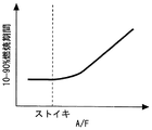
- FIG. 6 is a diagram showing a relationship between a 10 to 90% combustion period (main combustion period) and an air-fuel ratio (A / F).
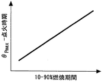
- FIG. 5 is a diagram showing a relationship between a parameter ( ⁇ Pmax -ignition timing) and a 10 to 90% combustion period.
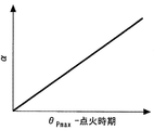
- FIG. 6 is a diagram showing a relationship between a parameter ⁇ and a parameter ( ⁇ Pmax -ignition timing) (that is, a tendency of the equation (3)). It is a flowchart of the routine performed in Embodiment 2 of this invention.
- FIG. 1 is a diagram for explaining a system configuration of an internal combustion engine 10 according to Embodiment 1 of the present invention.
- the system shown in FIG. 1 includes an internal combustion engine (for example, a spark ignition internal combustion engine) 10.
- a piston 12 is provided in the cylinder of the internal combustion engine 10.
- a combustion chamber 14 is formed on the top side of the piston 12 in the cylinder.
- An intake passage 16 and an exhaust passage 18 communicate with the combustion chamber 14.
- the intake port of the intake passage 16 is provided with an intake valve 20 that opens and closes the intake port, and the exhaust port of the exhaust passage 18 is provided with an exhaust valve 22 that opens and closes the exhaust port.
- the intake passage 16 is provided with an electronically controlled throttle valve 24.
- Each cylinder of the internal combustion engine 10 is provided with a fuel injection valve 26 for directly injecting fuel into the combustion chamber 14 (inside the cylinder) and an ignition plug 28 for igniting the air-fuel mixture. Further, an in-cylinder pressure sensor 30 for detecting the in-cylinder pressure P is incorporated in each cylinder.
- the system of the present embodiment includes an ECU (Electronic Control Unit) 40.
- ECU Electronic Control Unit
- various sensors for detecting the operating state of the internal combustion engine 10 such as a crank angle sensor 42 for detecting the engine speed are connected to the input portion of the ECU 40.
- Various actuators such as the throttle valve 24, the fuel injection valve 26, and the spark plug 28 described above are connected to the output portion of the ECU 40.
- the ECU 40 performs predetermined engine control such as fuel injection control and ignition control by driving the various actuators based on the sensor output and a predetermined program.
- the ECU 40 has a function of acquiring an output signal of the in-cylinder pressure sensor 30 by performing AD conversion in synchronization with the crank angle ⁇ .
- the in-cylinder pressure P at an arbitrary timing can be detected within a range allowed by the resolution of AD conversion.
- the ECU 40 has a function of calculating the value of the cylinder volume V determined by the position of the crank angle ⁇ according to the crank angle ⁇ .
- the absolute pressure correction value ⁇ P is calculated using the in-cylinder pressure P and the in-cylinder volume V at the two points in the adiabatic compression stroke together with the specific heat ratio ⁇ .
- ⁇ P (PV ⁇ ( ⁇ 2 ) ⁇ PV ⁇ ( ⁇ 2 ⁇ )) / (V ⁇ ( ⁇ 2 ) ⁇ V ⁇ ( ⁇ 2 ⁇ )) (1)
- ⁇ 2 is a predetermined second crank angle during the adiabatic compression stroke (details will be described later)
- ⁇ is a predetermined two-point crank angle used for performing absolute pressure correction.
- the crank angle interval (for example, 30 ° CA). Accordingly, a first crank angle ⁇ 1 described later is calculated as ( ⁇ 2 ⁇ ).
- the absolute pressure correction of the detection value of the in-cylinder pressure sensor 30 using the above equation (1) is performed for each cycle in each cylinder including the in-cylinder pressure sensor 30 (all cylinders in the internal combustion engine 10 of the present embodiment). To be executed. More specifically, in each cycle, the output signal of the in-cylinder pressure sensor 30 is acquired by performing AD conversion in synchronization with the crank angle ⁇ , so that the in-cylinder pressure waveform in a predetermined period (for example, the compression stroke and the expansion stroke) is obtained. Acquired and stored in the buffer of the ECU 40.
- the absolute pressure correction is executed using two points in the adiabatic compression process in the acquired in-cylinder pressure waveform, and the in-cylinder pressure waveform after the absolute pressure correction is stored again in the buffer.
- various combustion analysis values a calorific value Q (or a parameter PV ⁇ correlated with the calorific value Q)
- a combustion mass ratio MFB a combustion mass ratio MFB
- a combustion gravity center position CA50 combustion gravity center position CA50
- the calculation accuracy of the combustion analysis value and the absolute pressure accuracy for each cycle are used in supercharged lean burn combustion, mass EGR combustion, HCCI (premixed compression ignition) combustion, and ignition start control, which are being researched and developed in recent years. It is especially demanded.
- noise base noise
- noise may be superimposed on the in-cylinder pressure sensor 30, the ECU 40, and the wire harness that connects the in-cylinder pressure sensor 30 and the ECU 40.
- an error occurs when the absolute pressure correction value is calculated by the above method.
- the noise causes a large error in the combustion analysis value (for example, the combustion gravity center position CA50 or the indicated torque) during low load combustion. If such an error occurs, it may not be possible to improve the fuel efficiency and drivability as intended.
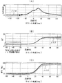
- FIG. 2 is a diagram showing a result of simulating the influence of noise superimposition on the detection value of the in-cylinder pressure sensor 30. More specifically, FIG. 2A is a diagram in which white noise equivalent to the base noise is superimposed on an in-cylinder pressure waveform on which noise is not superimposed.
- 2 (B) and 2 (C) are respectively the in-cylinder pressures corrected by the absolute pressure correction using the two points indicated by black circles in FIG. 2 (A) and the above equation (1).
- the waveforms of the parameter PV ⁇ and the combustion mass ratio MFB calculated using P are respectively shown.
- the parameter PV ⁇ is a parameter highly correlated with the in-cylinder calorific value Q.
- the calorific value Q is calculated using the following equation (2) instead of the parameter PV ⁇ , the calorific value Q
- the waveform is the same as that shown in FIG. In each figure of FIG. 2, the waveform shown by the solid line shows a waveform without noise, and the area shown around the waveform shown by the solid line shows that the value varies due to the influence of noise. Yes.
- the two points set by the above-described conventional method are the crank angle at a timing far away from the compression top dead center, and are greatly affected by the base noise. As a result, a large error occurs in the absolute pressure correction value ⁇ P calculated using these two points.
- 2B and 2C also show the parameter PV ⁇ (or the calorific value Q) and the combustion mass ratio MFB calculated using such an absolute pressure correction value ⁇ P having a large error. As shown, a large error occurs.
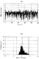
- FIG. 3 is a diagram showing the influence of the error of the absolute pressure correction due to the influence of the base noise on the calculation of the combustion analysis value (for example, the combustion gravity center position CA50). More specifically, FIG. 3A shows the in-cylinder pressure P after correction by absolute pressure correction using the two points indicated by black circles in FIG. 2A and the above equation (1). A waveform of the combustion center-of-gravity position CA50 calculated over a predetermined cycle (here, 500 cycles) is shown. FIG. 3B is a diagram showing the variation of the combustion center of gravity position CA50 shown in FIG. 3A using a histogram. As shown in FIGS. 3A and 3B, the calculated value in each cycle of the combustion center-of-gravity position CA50 may vary greatly due to an error in absolute pressure correction due to the influence of base noise. I understand.
- the cause of the increase in the absolute pressure correction error in the conventional method is that there are two areas in the adiabatic compression process used for the calculation of the absolute pressure correction value ⁇ P. 2 points in the region where the S / N ratio is low) are used as fixed values. Therefore, although not actually used in the present embodiment, the following measures can be considered.
- the absolute pressure correction value ⁇ P varies when a plurality of absolute pressure correction values ⁇ P are calculated using two different crank angles in the same cycle. Since the base noise is noise equivalent to white noise (normal distribution), a countermeasure may be considered in which a value obtained by averaging the N absolute pressure correction values ⁇ P calculated in the same cycle is used. Thereby, the influence of noise on the absolute pressure correction value ⁇ P can be reduced to 1 / N.
- operating conditions such as conditions under which intake valve slow closing control is performed, there is a problem that it is not possible to secure an N number sufficient to perform sufficient average processing.
- a measure to use an average value of the absolute pressure correction value ⁇ P calculated in each cycle over a plurality of cycles may be considered. As a result, it is possible to secure a sufficient number N for reducing the base noise. However, this measure cannot be used during transient operation that changes to operating conditions different from the previous cycle. Further, since it becomes impossible to determine the absolute pressure correction value ⁇ P for each cycle, it becomes impossible to acquire a desired combustion analysis value for each cycle and reflect the acquired result on the combustion control of the next cycle.
- a shield wire is used, or a structure in which the output circuit of the sensor is separated into a low pressure part and a high pressure part is used. It is also possible to take measures against noise. However, there is a concern that this measure may cause a significant cost increase, and its effect is limited.
- the crank angle (hereinafter referred to as “the in-cylinder pressure sensor 30 output value) is maximized during the combustion period.
- the crank angle advanced by the parameter ⁇ with respect to the in-cylinder pressure maximum crank angle ⁇ Pmax so as to be the timing in the adiabatic compression stroke that is retarded from the ignition timing is set as the second crank angle ⁇ 2.
- a crank angle advanced by a predetermined crank angle interval ⁇ with respect to the second crank angle ⁇ 2 is set as the first crank angle ⁇ 1 . That is, according to the method of the present embodiment, the first and second crank angles ⁇ 1 and ⁇ 2 are varied according to the in-cylinder pressure maximum crank angle ⁇ Pmax .
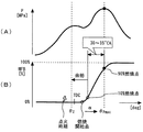
- FIG. 4 is a diagram for explaining a parameter ⁇ setting method used for setting the second crank angle ⁇ 2 in the first embodiment of the present invention.
- the second timing is set so that the timing is retarded from the ignition timing and reaches the combustion start point (the point at which the combustion mass ratio MFB starts to increase from 0%). It is as setting the crank angle theta 2. More specifically, in this embodiment, the second crank angle theta 2 are set in the vicinity of the combustion start point.
- the in-cylinder pressure maximum crank angle ⁇ Pmax generally corresponds to the crank angle when the combustion mass ratio MFB is 90%.
- the combustion period in which the combustion mass ratio MFB is 10 to 90% (that is, the so-called “main combustion period”) is approximately 30 to 35 ° CA even when the change in the engine speed is taken into consideration. Therefore, in the present embodiment, in order to set the second crank angle ⁇ 2 at the above timing, the parameter ⁇ is predetermined within a combustion period (main combustion period) of 10 to 90% with respect to the in-cylinder pressure maximum crank angle ⁇ Pmax . Is set as a value advanced by a period including a margin period (a period shorter than the main combustion period of about 5 ° CA). In this embodiment, it is assumed that the parameter ⁇ is set as a fixed value regardless of the operating conditions.
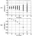
- FIG. 5 shows the influence (A) of the base noise on the numerator of the absolute pressure correction value ⁇ P and the change in the denominator size (B) of the absolute pressure correction value ⁇ P in relation to the crank angle interval ⁇ .
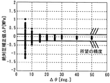
- FIG. 6 is a diagram showing the relationship between the degree of variation in the absolute pressure correction value ⁇ P due to the influence of base noise and the crank angle interval ⁇ .
- the molecular component of the absolute pressure correction value ⁇ P is (PV ⁇ ( ⁇ 2 ) ⁇ PV ⁇ ( ⁇ 2 ⁇ )) from the above equation (1).
- the first crank angle ⁇ 1 is further away from the compression top dead center. Therefore, as shown in FIG. 5A, the larger the crank angle interval ⁇ , the more the influence of the base noise on the molecular component of the absolute pressure correction value ⁇ P is amplified, and the error of the molecular component increases.
- the denominator component of the absolute pressure correction value ⁇ P is (V ⁇ ( ⁇ 2 ) ⁇ V ⁇ ( ⁇ 2 ⁇ )) from the above equation (1). Therefore, as shown in FIG. 5B, as the crank angle interval ⁇ increases, the denominator component of the absolute pressure correction value ⁇ P increases on the minus side.
- the influence of the change in the crank angle interval ⁇ on the absolute pressure correction value ⁇ P is an error due to the influence of the base noise of the molecular component of the absolute pressure correction value ⁇ P.
- the increase of the denominator component (as an absolute value) is larger than the amount of amplification of. Therefore, as shown in FIG. 6, it can be said that the error (variation) of the absolute pressure correction value ⁇ P decreases as the crank angle interval ⁇ increases. Therefore, in the present embodiment, the crank angle interval ⁇ is set so that the calculation accuracy of the absolute pressure correction value ⁇ P falls within the desired accuracy.
- An example of such a crank angle interval ⁇ is 30 ° CA.
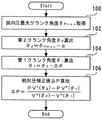
- FIG. 7 is a flowchart showing a routine executed by the ECU 40 in order to realize the absolute pressure correction in the first embodiment of the present invention. Note that this routine is repeatedly executed for each cylinder in each cycle of the internal combustion engine 10.
- the ECU 40 first uses the waveform of the output value (AD conversion value) of the in-cylinder pressure sensor 30, and the in-cylinder pressure maximum crank angle ⁇ Pmax, which is the crank angle when the output value becomes maximum. Is acquired (step 100).
- the ECU 40 calculates a value obtained by subtracting the parameter ⁇ from the acquired in-cylinder pressure maximum crank angle ⁇ Pmax as the second crank angle ⁇ 2 (step 102).
- the parameter ⁇ is a fixed value preliminarily adapted according to the method described above with reference to FIG. According to the process of step 102, so that the crank angle has advanced by parameter ⁇ with respect to the cylinder pressure up to the crank angle theta Pmax is calculated as the second crank angle theta 2.
- ECU 40 calculates a value obtained by subtracting the crank angle interval ⁇ from the second crank angle theta 2 calculated as the first crank angle theta 1 (step 104).
- the crank angle interval ⁇ is a value set in advance as a size (for example, 30 ° CA) that can ensure the accuracy of the absolute pressure correction value ⁇ P.
- step 104 so that the crank angle has advanced by a crank angle interval ⁇ with respect to the second crank angle theta 2 is calculated as a first crank angle theta 1.
- the ECU 40 uses the second crank angle ⁇ 2 and the first crank angle ⁇ 1 calculated as described above to calculate an absolute pressure correction value ⁇ P according to the above equation (1) (step 106).
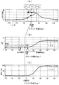
- FIG. 8 is a diagram showing a result of simulating the influence of noise superposition on the detection value of the in-cylinder pressure sensor 30 while applying the absolute pressure correction method according to the first embodiment of the present invention. More specifically, FIG. 8A is a diagram in which white noise equivalent to that in FIG. 2A is superimposed on an in-cylinder pressure waveform on which noise is not superimposed.
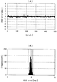
- FIG. 9 is a diagram showing a calculation result of a combustion analysis value (as an example, the combustion gravity center position CA50) using the in-cylinder pressure P corrected by the absolute pressure correction method according to the first embodiment of the present invention.
- a combustion analysis value as an example, the combustion gravity center position CA50
- the second crank angle theta 2 is set to a timing in the vicinity of the combustion start point.
- the second crank angle ⁇ 2 set in this way is close to the compression top dead center.
- a crank angle advanced by the crank angle interval ⁇ with respect to the second crank angle ⁇ 2 is set as the first crank angle ⁇ 1 .
- the acquisition of the in-cylinder pressure maximum crank angle ⁇ Pmax does not require any preliminary calculation. That is, the in-cylinder pressure maximum crank angle ⁇ Pmax can be easily detected by only obtaining the output value (AD conversion value) of the in-cylinder pressure sensor 30 while using a peak hold function for storing the maximum value, for example. Then, based on thus readily obtainable cylinder pressure up to the crank angle theta Pmax, the second crank angle theta 2 and advanced by parameters set in advance alpha, further predetermined crank from the second crank angle theta 2 since the calculated first crank angle theta 1 which is advanced by an angle interval [Delta] [theta], it does not require special processing load.
- the calculation of the first and second crank angles ⁇ 1 and ⁇ 2 based on the maximum in-cylinder pressure crank angle ⁇ Pmax is performed for each cycle, so that it does not depend on operating conditions.
- Two appropriate points ( ⁇ 1 , ⁇ 2 ) can be calculated. For this reason, since it is not necessary to have a map for each operating condition for calculating these two points ( ⁇ 1 , ⁇ 2 ), an increase in the number of matching man-hours can be suppressed.
- the detection of the in-cylinder pressure sensor 30 that effectively suppresses the influence of noise without incurring an increase in cost, an increase in man-hours, and an increase in calculation processing load.
- the absolute pressure correction of the value can be performed.
- crank angle ⁇ 1 setting the crank angle that is advanced by the parameter ⁇ from the cylinder pressure up to the crank angle theta Pmax as the second crank angle theta 2 as the second crank angle theta 2
- the crank angle advanced from the in-cylinder pressure maximum crank angle ⁇ Pmax by a predetermined crank angle interval is set as the first crank angle ⁇ 1
- the first crank angle ⁇ 1 is set.
- crank angle which is retarded by the crank angle interval ⁇ from the crank angle theta 1 may be set as the second crank angle theta 2.
- a crank angle advanced from the maximum in-cylinder pressure crank angle ⁇ Pmax by a predetermined crank angle interval (referred to as “fourth crank angle interval” for convenience) is set as the first crank angle ⁇ 1
- the maximum in-cylinder pressure crank angle the fourth crank angle interval smaller predetermined crank angle intervals than (for convenience referred to as a "fifth crank angle interval") advanced by the crank angle from theta Pmax may be set as the second crank angle theta 2.
- the second crank angle ⁇ 2 is set to a crank angle on the advance side from the compression top dead center
- the first crank angle theta 1 is set to a crank angle of advance side of ignition timing.
- the second crank angle in the present invention may be arbitrarily set according to the maximum cylinder pressure crank angle as long as it is a timing retarded from the ignition timing and up to the combustion start point. is there.
- the first crank angle in the present invention is set to a crank angle that is retarded from the ignition timing as long as the crank angle is advanced by a predetermined crank angle interval with respect to the second crank angle. It may be a thing.
- the absolute pressure correction method using the parameter PV ⁇ having a linear correlation with the calorific value Q in the cylinder has been described as an example.
- the absolute pressure correction value calculated using the first and second crank angles during the adiabatic compression stroke in the present invention may be calculated using the in-cylinder heat generation amount Q.
- the calorific value Q can be calculated by the following equation (2). That is, the heat generation amount Q can be calculated by integrating the in-cylinder heat generation rate dQ / d ⁇ using the detection value of the in-cylinder pressure sensor 30 with the crank angle ⁇ .
- the “acquiring means” in the first invention is realized by the ECU 40 executing the process of step 100, and the ECU 40 executes the processes of steps 102 to 106.
- the “absolute pressure correcting means” in the first invention is realized.
- the parameter ⁇ is the “first crank angle interval” in the second invention, and the crank angle interval ⁇ is the “second crank angle interval” in the second invention. It corresponds.
- Embodiment 2 a second embodiment of the present invention will be described with reference mainly to FIGS.
- the system of this embodiment can be realized by causing the ECU 40 to execute a routine shown in FIG. 13 described later instead of the routine shown in FIG. 7 using the hardware configuration shown in FIG.
- slow combustion such as lean combustion, mass EGR combustion, or retarded combustion for warming up the catalyst
- the ignition timing (combustion start point) is delayed (the ignition delay period is lengthened).
- the main combustion period (10 to 90% combustion period) is also delayed.
- FIG. 10 is a graph showing the relationship between the 10 to 90% combustion period (main combustion period) and the air-fuel ratio (A / F). Taking the air-fuel ratio as an example, as shown in FIG. 10, as the air-fuel ratio becomes leaner than the stoichiometric air-fuel ratio, the combustion speed becomes slower and the combustion period of 10 to 90% becomes longer.
- the second crank is set using the parameter ⁇ set for the conditions during normal combustion (for example, the air-fuel ratio is the stoichiometric air-fuel ratio). If the angle ⁇ 2 is calculated, the crank angle after the combustion has already started (that is, the crank angle during a period other than the adiabatic compression stroke) can be selected as the second crank angle ⁇ 2 . As a result, there is a concern that an error occurs in the absolute pressure correction value ⁇ P.
- FIG. 11 is a graph showing the relationship between the parameter ( ⁇ Pmax -ignition timing) and the 10 to 90% combustion period.
- FIG. 12 is a diagram showing the relationship between the parameter ⁇ and the parameter ( ⁇ Pmax -ignition timing) (that is, the tendency of the above equation (3)).
- the parameter ( ⁇ Pmax -ignition timing) is a period including an ignition delay period from ignition (discharge) to ignition (combustion starts) and a subsequent main combustion period (10 to 90% combustion period). It is defined. Therefore, as shown in FIG. 11, it can be seen that the parameter ( ⁇ Pmax -ignition timing) has a correlation with the 10 to 90% combustion period. From the relationship shown in FIGS. 10 and 11, it can be seen that the parameter ( ⁇ Pmax -ignition timing) is also correlated with the air-fuel ratio, which is a parameter that affects the ignition delay period and the main combustion period.
- the parameter ( ⁇ Pmax -ignition timing) is also used for parameters that affect the ignition delay period and the main combustion period such as the EGR gas amount other than the air-fuel ratio and the intake valve timing. It can be said that there is a correlation as well as the air-fuel ratio. Therefore, in the present embodiment, as shown in FIG. 12, the parameter ⁇ for determining the second crank angle ⁇ 2 as the parameter ( ⁇ Pmax ⁇ ignition timing) increases using the relationship of the above equation (3). Was made larger.
- the parameter ( ⁇ Pmax -ignition timing) is the normal combustion Longer than. Accordingly, the parameter ⁇ is set to a larger value than that during normal combustion. More specifically, the parameter increases as the air-fuel ratio becomes leaner than the stoichiometric air-fuel ratio.
- the parameter ⁇ is set to a larger value than that during normal combustion. More specifically, the parameter increases as the air-fuel ratio becomes leaner than the stoichiometric air-fuel ratio.
- the second crank angle ⁇ 2 is set so as to ensure the crank angle during the adiabatic compression stroke.
- the calculation accuracy of the absolute pressure correction value ⁇ P can be increased.
- the parameter ⁇ calculated in this way can be applied to all operating conditions, and in determining an appropriate parameter ⁇ corresponding to the ignition delay period and the main combustion period, the number of compatible man-hours increases. Can be avoided.
- the parameter ( ⁇ Pmax -ignition timing) is used instead of the 10 to 90% combustion period when calculating the parameter ⁇ .
- the 10 to 90% combustion period is a value calculated after calculating the combustion mass ratio MFB using the detection value of the in-cylinder pressure sensor 30, so that an absolute pressure correction was performed in order to obtain an accurate value. It is necessary to use the value of the later in-cylinder pressure P. Therefore, it is not appropriate to use the 10 to 90% combustion period in a state where the absolute pressure correction is not performed in order to calculate the parameter ⁇ used for the absolute pressure correction.
- the parameter ⁇ can be appropriately calculated based on the parameter ( ⁇ Pmax ⁇ ignition timing) that is not affected by whether or not absolute pressure correction is performed.
- the parameter ( ⁇ Pmax -ignition timing) uses the in-cylinder pressure maximum crank angle ⁇ Pmax that can be easily obtained using the peak hold function or the like, as described in the first embodiment, together with the ignition timing. For this reason, the parameter ⁇ corresponding to the ignition delay period and the main combustion period can be calculated for each cycle without increasing the processing load.
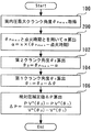
- FIG. 13 is a flowchart showing a routine executed by the ECU 40 in order to realize the absolute pressure correction in the second embodiment of the present invention.
- the same steps as those shown in FIG. 7 in the first embodiment are denoted by the same reference numerals, and the description thereof is omitted or simplified.
- the ECU 40 calculates the parameter ⁇ based on the parameter ( ⁇ Pmax ⁇ ignition timing) according to the above equation (3) (step 200).
- an adaptive value set in advance is used as the coefficient k in the equation (3).
- the parameter ⁇ corresponding to the ignition delay period and the main combustion period can be calculated for each cycle without causing an increase in the adaptation man-hours and an increase in the processing load. It becomes like this.
- Embodiment 3 FIG. Next, Embodiment 3 of the present invention will be described with reference mainly to FIG. 14 and FIG.
- the system of the present embodiment can be realized by causing the ECU 40 to execute a routine shown in FIG. 15 described later instead of the routine shown in FIG. 13 using the hardware configuration shown in FIG.
- Figure 14 is a diagram for explaining a first crank angle theta 1 of the setting method at the time of combustion under the intake air amount is small situations.
- the intake air amount is small, that is, during low load operation, the in-cylinder pressure P is unlikely to increase during the compression stroke.
- the crank angle interval ⁇ is set based on the idea described above with reference to FIG. 6, the in-cylinder pressure P ( ⁇ 1 ) at the first crank angle ⁇ 1 may be too low. is there.
- the in-cylinder pressure P ( ⁇ 1 ) is low, the in-cylinder pressure P ( ⁇ 1 ) is easily affected by noise. For this reason, there is a concern that the error of the absolute pressure correction value ⁇ P becomes large.
- crank angle theta 1 when calculating the first crank angle theta 1, cylinder pressure P at the first crank angle theta 1 which is obtained by subtracting the crank angle interval ⁇ from the second crank angle theta 2 (theta 1 ) Is less than or equal to a predetermined determination value P min (for example, 0.4 MPa), as shown in FIG. 14, the crank angle at the timing when the in-cylinder pressure P is slightly higher than the determination value P min.
- the crank angle interval correction value ⁇ ′ is calculated so that becomes the first crank angle ⁇ 1 .
- the operating condition (mainly the intake air amount) at the time of performing this process is associated with ⁇ ′. I decided to learn. Then, when it becomes the same operating conditions in the next and subsequent cycles was to calculate the first crank angle theta 1 to obtain the crank angle interval [Delta] [theta] 'after the above modifications.
- FIG. 15 is a flowchart showing a routine executed by the ECU 40 in order to realize the absolute pressure correction in the third embodiment of the present invention.
- the same steps as those shown in FIG. 13 in the second embodiment are denoted by the same reference numerals, and the description thereof is omitted or simplified.
- step 104 after calculating the first crank angle ⁇ 1 in step 104, the ECU 40 determines whether the in-cylinder pressure P ( ⁇ 1 ) at the first crank angle ⁇ 1 is higher than the determination value P min . It is determined whether or not (step 300). As a result, if the determination in step 300 is satisfied, the ECU 40 immediately proceeds to step 106 and calculates the absolute pressure correction value ⁇ P.
- step 300 determines whether or not learning has been completed under the same operating conditions (mainly intake air amount (load factor KL) conditions) as the operating conditions in the current processing cycle (step 302).
- the ECU 40 determines that the crank angle at the timing when the in-cylinder pressure P is slightly higher than the determination value P min becomes the first crank angle ⁇ 1.
- a correction value ⁇ ′ of the crank angle interval for doing so is calculated, and the current operating condition is held as a learning value in association with the correction value ⁇ ′ (step 304).
- the ECU 40 calculates the first crank angle ⁇ 1 as a value obtained by subtracting the corrected crank angle interval ⁇ ′ from the second crank angle ⁇ 2 (step 306).
- step 302 determines whether learning has already been performed. If it is determined in step 302 that learning has already been performed, the ECU 40 acquires the crank angle interval ⁇ ′ calculated in the past under the same operating conditions as the current processing cycle ( Step 308), go to step 306.
- Embodiment 4 FIG. Next, a fourth embodiment of the present invention will be described with reference mainly to FIG.
- the system of the present embodiment can be realized by causing the ECU 40 to execute a routine shown in FIG. 16 described later instead of the routine shown in FIG. 13 using the hardware configuration shown in FIG.
- the combustion mass ratio MFB at an arbitrary crank angle ⁇ can be calculated according to the following equation (4) using a parameter PV ⁇ correlated with the calorific value Q in the cylinder.
- MFB (PV ⁇ ( ⁇ ) -PV ⁇ ( ⁇ sta)) / (PV ⁇ ( ⁇ fin) -PV ⁇ ( ⁇ sta)) ⁇ (4)
- ⁇ sta is the combustion start point (combustion start timing)
- ⁇ fin is the combustion end point (combustion end timing).
- the combustion mass ratio MFB can also be calculated using the calorific value Q that can be calculated using the above equation (2) instead of the parameter PV ⁇ .
- the influence of the base noise is recognized as can be seen by comparing FIG. 8B and FIG. It is possible to obtain a waveform of the parameter PV ⁇ that is greatly reduced. However, as can be seen from FIG. 8B, at the crank angle far away from the compression top dead center, the influence of the base noise remains at a small level in the waveform of the parameter PV ⁇ .
- the parameter PV ⁇ (( When calculating the combustion mass ratio MFB by calculating the calorific value Q), using a crank angle far away from the compression top dead center as in the conventional method as the combustion start point ⁇ sta is This may be a cause of deterioration in accuracy in calculating the combustion mass ratio MFB.
- the parameter ⁇ is advanced from the in-cylinder pressure maximum crank angle ⁇ Pmax.
- the second crank angle ⁇ 2 calculated as an angled crank angle is used as the combustion start point ⁇ sta .
- FIG. 16 is a flowchart showing a routine executed by the ECU 40 in order to realize the calculation of the combustion mass ratio MFB in the fourth embodiment of the present invention.
- the same steps as those shown in FIG. 13 in the second embodiment are denoted by the same reference numerals, and the description thereof is omitted or simplified.
- the calculation process of the combustion mass ratio MFB of the present embodiment is the same as the absolute pressure correction method described in the other embodiments 1 or 3. It may be executed in combination.
- the ECU 40 sets the second crank angle ⁇ 2 calculated in step 102 as the combustion start point ⁇ sta used in the equation (4).
- the combustion mass ratio MFB is calculated according to the equation (4) (step 400).
- the combustion end point ⁇ fin in the above equation (4) can be acquired as the crank angle when the parameter PV ⁇ calculated using the cylinder pressure P after the absolute pressure correction reaches the maximum value.
- the ECU 40 calculates the combustion center-of-gravity position CA50 as a combustion analysis value obtained by using the calculated value of the combustion mass ratio MFB (step 402).
- the combustion mass ratio MFB is calculated by calculating the combustion mass ratio MFB using the second crank angle ⁇ 2 calculated based on the maximum in-cylinder pressure crank angle ⁇ Pmax as the combustion start point ⁇ sta. It is possible to reduce the influence of base noise on PV ⁇ ( ⁇ sta ) that is a calorific value correlation value at the start point ⁇ sta . As described above, by using the absolute pressure correction value ⁇ P that greatly reduces the influence of the base noise, and using the second crank angle ⁇ 2 as the combustion start point ⁇ sta , the calculation accuracy of the combustion mass ratio MFB is further improved. Can be made.
- the “burning mass ratio calculating means” in the seventh aspect of the present invention is realized by the ECU 40 executing the processing of step 400 described above.
Landscapes
- Engineering & Computer Science (AREA)
- Chemical & Material Sciences (AREA)
- Combustion & Propulsion (AREA)
- Mechanical Engineering (AREA)
- General Engineering & Computer Science (AREA)
- Physics & Mathematics (AREA)
- General Physics & Mathematics (AREA)
- Combined Controls Of Internal Combustion Engines (AREA)
- Electrical Control Of Ignition Timing (AREA)
- Computer Hardware Design (AREA)
- Microelectronics & Electronic Packaging (AREA)
Abstract
筒内圧力Pを検出する筒内圧センサ(30)を備える。筒内圧最大クランク角度θPmaxを基準として、断熱圧縮行程において第1クランク角度θ1および第2クランク角度θ2を設定し、これらのクランク角度θ1、θ2でのそれぞれの筒内圧力Pと筒内容積Vとを用いて絶対圧補正値ΔPを算出する。点火時期より遅角側の断熱圧縮行程中のタイミングとなるように筒内圧最大クランク角度θPmaxに対して進角したクランク角度を第2クランク角度θ2として設定して絶対圧補正に用いる。
Description
この発明は、内燃機関の制御装置に係り、特に、筒内圧センサの検出値を利用して各種エンジン制御を実行する装置として好適な内燃機関の制御装置に関する。
従来、例えば特許文献1には、筒内圧センサを備える内燃機関の制御装置が開示されている。一般的に、筒内圧センサの検出値は大気圧に対する相対圧であるため、絶対圧補正を行う必要がある。そこで、上記従来の制御装置では、ポアソンの関係式を利用し、吸気弁が閉じてから点火時期に至るまでの断熱圧縮行程における2点のクランク角度での筒内圧力と筒内容積とを比熱比とともに用いて(すなわち、パラメータPVκを用いて)絶対圧補正値を算出するようにしている。
尚、出願人は、本発明に関連するものとして、上記の文献を含めて、以下に記載する文献を認識している。
従来において断熱圧縮行程における2点のクランク角度での筒内圧力と筒内容積とを用いて(より具体的には、例えば、上記特許文献1のようにパラメータPVκを用いて、或いは筒内圧センサの検出値に基づいて算出する発熱量Qを用いて)絶対圧補正値を算出する際には、演算処理の簡素化のため、すべての運転条件において吸気弁の閉弁タイミング等の影響を回避できるようなタイミングでのクランク角度(固定値)が上記2点のクランク角度として用いられてきた。
筒内圧センサ、ECU、および筒内圧センサとECUとを接続するワイヤハーネス等には、ノイズが重畳し得る。このような電磁ノイズが筒内圧センサの検出値に重畳すると、上記の手法で絶対圧補正値を算出した際に、誤差が発生してしまう。この誤差の影響は、圧縮上死点から離れるほど大きくなる。しかしながら、従来において絶対圧補正値の算出によく用いられるタイミングでの2点のクランク角度は、圧縮上死点から大きく離れた位置でのものであった。このため、そのような2点のクランク角度を用いて絶対圧補正を行った際に大きな誤差が発生するという問題があった。
この発明は、上述のような課題を解決するためになされたもので、筒内圧センサにより検出される筒内圧力に対して、コストアップ、適合工数の増加、および演算処理負荷の増大を招くことなく、効果的にノイズ影響を抑制することのできる絶対圧補正を行えるようにした内燃機関の制御装置を提供することを目的とする。
第1の発明は、内燃機関の制御装置であって、
筒内圧力を検出する筒内圧センサと、
燃焼期間中に前記筒内圧センサにより検出される筒内圧力が最大となる筒内圧最大クランク角度を取得する取得手段と、
前記筒内圧最大クランク角度を基準として、吸気弁が閉じてから燃焼が開始するまでの断熱圧縮行程において第1クランク角度と当該第1クランク角度よりも遅角側の第2クランク角度とを設定し、前記第1クランク角度および前記第2クランク角度でのそれぞれの筒内圧力と筒内容積とを用いて、前記筒内圧センサにより検出される筒内圧力の絶対圧補正を実行する絶対圧補正手段と、
を備え、
前記絶対圧補正手段は、点火時期より遅角側の断熱圧縮行程中のタイミングとなるように前記筒内圧最大クランク角度に対して進角したクランク角度を前記第2クランク角度として設定して前記絶対圧補正に用いることを特徴とする。
また、第2の発明は、第1の発明において、
前記絶対圧補正手段は、前記筒内圧最大クランク角度に対して第1クランク角度間隔だけ進角したクランク角度を前記第2クランク角度として設定し、前記第2クランク角度に対して第2クランク角度間隔だけ進角したクランク角度を前記第1クランク角度として設定することを特徴とする。
前記絶対圧補正手段は、前記筒内圧最大クランク角度に対して第1クランク角度間隔だけ進角したクランク角度を前記第2クランク角度として設定し、前記第2クランク角度に対して第2クランク角度間隔だけ進角したクランク角度を前記第1クランク角度として設定することを特徴とする。
また、第3の発明は、第1の発明において、
前記絶対圧補正手段は、前記筒内圧最大クランク角度に対して第3クランク角度間隔だけ進角したクランク角度を前記第1クランク角度として設定し、前記第1クランク角度に対して第2クランク角度間隔だけ遅角したクランク角度を前記第2クランク角度として設定することを特徴とする。
前記絶対圧補正手段は、前記筒内圧最大クランク角度に対して第3クランク角度間隔だけ進角したクランク角度を前記第1クランク角度として設定し、前記第1クランク角度に対して第2クランク角度間隔だけ遅角したクランク角度を前記第2クランク角度として設定することを特徴とする。
また、第4の発明は、第2の発明において、
前記絶対圧補正手段は、前記筒内圧最大クランク角度と点火時期との差に基づいて前記第1クランク角度間隔を設定することを特徴とする。
前記絶対圧補正手段は、前記筒内圧最大クランク角度と点火時期との差に基づいて前記第1クランク角度間隔を設定することを特徴とする。
また、第5の発明は、第1~第4の発明の何れか1つにおいて、
前記絶対圧補正手段は、前記第2クランク角度として、燃焼開始点近傍のクランク角度を設定することを特徴とする
前記絶対圧補正手段は、前記第2クランク角度として、燃焼開始点近傍のクランク角度を設定することを特徴とする
また、第6の発明は、第1~第5の発明の何れか1つにおいて、
前記絶対圧補正手段は、前記第1クランク角度を、所定値よりも高い筒内圧力でのクランク角度に設定することを特徴とする。
前記絶対圧補正手段は、前記第1クランク角度を、所定値よりも高い筒内圧力でのクランク角度に設定することを特徴とする。
また、第7の発明は、第1~第6の発明の何れか1つにおいて、
前記絶対圧補正手段による補正後の筒内圧力を用い、かつ、前記第2クランク角度を燃焼開始点として用いて、燃焼質量割合を算出する燃焼質量割合算出手段を更に備えることを特徴とする。
前記絶対圧補正手段による補正後の筒内圧力を用い、かつ、前記第2クランク角度を燃焼開始点として用いて、燃焼質量割合を算出する燃焼質量割合算出手段を更に備えることを特徴とする。
第1~第3の発明によれば、筒内圧最大クランク角度を取得したうえで、この筒内圧最大クランク角度を基準として、絶対圧補正に用いる第1および第2クランク角度が断熱圧縮行程中のタイミングとして設定される。特に、第2クランク角度としては、点火時期より遅角側の断熱圧縮行程中のタイミングとなるように筒内圧最大クランク角度に対して進角したクランク角度が用いられる。このように設定された第2クランク角度は、圧縮上死点に近いタイミングであることで、ノイズの影響を受けにくい。このため、当該第2クランク角度を用いることで、ノイズの影響による絶対圧補正値の誤差を低減できるようになる。また、筒内圧センサにより検出される筒内圧の波形から容易に取得可能な筒内圧最大クランク角度を基準として第1および第2クランク角度を設定するようにしたことで、適合工数の増加および演算処理負荷の増大を抑制しつつ、第1および第2クランク角度を取得できるようになる。更に、このような手法によれば、ハードウェア面でのノイズ対策或いは筒内圧力の取得間隔を短縮するための制御装置の高性能化といったコストアップ要因をも回避することができる。以上のように、本発明によれば、筒内圧センサにより検出される筒内圧力に対して、コストアップ、適合工数の増加、および演算処理負荷の増大を招くことなく、効果的にノイズ影響を抑制することのできる絶対圧補正を行えるようにすることができる。
第4の発明によれば、筒内圧最大クランク角度と点火時期との差に基づいて第1クランク角度間隔が設定される。これにより、緩慢燃焼が行われる場合であっても、点火時期から燃焼開始点までの着火遅れ期間およびその後の主燃焼期間の変化に応じた適切な第1クランク角度間隔を設定できるようになる。また、この場合に用いているパラメータは、取得の容易な筒内圧最大クランク角度と点火時期である。このため、適合工数の増加および演算処理負荷の増大を招くことなく、適切な第1クランク角度間隔を設定できるようになる。
第5の発明によれば、圧縮上死点に近いタイミングであることで、ノイズの影響を受けにくいタイミングに第2クランク角度を設定することができる。
第6の発明によれば、低負荷運転時において、第1クランク角度での筒内圧力が低すぎることに起因して絶対圧補正の精度が低下するのを防止することができる。
第7の発明によれば、上記絶対圧補正手段による補正後の筒内圧力を用いることによるノイズ影響の低減に加え、上記第2クランク角度を燃焼開始点とすることによる燃焼開始点での発熱量(もしくは発熱量相関値)へのノイズ影響の低減とによって、燃焼質量割合の算出精度を向上させることができる。
実施の形態1.
[実施の形態1のシステム構成]
図1は、本発明の実施の形態1における内燃機関10のシステム構成を説明するための図である。
図1に示すシステムは、内燃機関(一例として、火花点火式内燃機関)10を備えている。内燃機関10の筒内には、ピストン12が設けられている。筒内におけるピストン12の頂部側には、燃焼室14が形成されている。燃焼室14には、吸気通路16および排気通路18が連通している。
[実施の形態1のシステム構成]
図1は、本発明の実施の形態1における内燃機関10のシステム構成を説明するための図である。
図1に示すシステムは、内燃機関(一例として、火花点火式内燃機関)10を備えている。内燃機関10の筒内には、ピストン12が設けられている。筒内におけるピストン12の頂部側には、燃焼室14が形成されている。燃焼室14には、吸気通路16および排気通路18が連通している。
吸気通路16の吸気ポートには、当該吸気ポートを開閉する吸気弁20が設けられており、排気通路18の排気ポートには、当該排気ポートを開閉する排気弁22が設けられている。また、吸気通路16には、電子制御式のスロットルバルブ24が設けられている。
内燃機関10の各気筒には、燃焼室14内(筒内)に直接燃料を噴射するための燃料噴射弁26、および、混合気に点火するための点火プラグ28が、それぞれ設けられている。更に、各気筒には、筒内圧力Pを検出するための筒内圧センサ30が組み込まれている。
更に、本実施形態のシステムは、ECU(Electronic Control Unit)40を備えている。ECU40の入力部には、上述した筒内圧センサ30に加え、エンジン回転数を検出するためのクランク角センサ42等の内燃機関10の運転状態を検出するための各種センサが接続されている。また、ECU40の出力部には、上述したスロットルバルブ24、燃料噴射弁26および点火プラグ28等の各種アクチュエータが接続されている。ECU40は、それらのセンサ出力と所定のプログラムとに基づいて上記各種のアクチュエータを駆動することにより、燃料噴射制御および点火制御等の所定のエンジン制御を行うものである。また、ECU40は、筒内圧センサ30の出力信号を、クランク角度θと同期させてAD変換して取得する機能を有している。これにより、AD変換の分解能が許す範囲で、任意のタイミングにおける筒内圧力Pを検出することができる。更に、ECU40は、クランク角度θの位置によって決まる筒内容積Vの値を、クランク角度θに応じて算出する機能を有している。
[実施の形態1における筒内圧センサの検出値の絶対圧補正手法]
(絶対圧補正の精度確保に関する課題)
一般的に、筒内圧センサの検出値(出力値)は相対圧であるため、これを絶対圧化する補正(絶対圧補正)が行われる。筒内圧センサ30の検出値を利用して絶対圧補正を行う手法として、例えば、次の(1)式を利用した手法が知られている。この手法は、断熱過程とみなした圧縮行程(より具体的には、吸気弁20が閉じてから燃焼が開始するまでの期間)において成立するポアソンの関係式(PVκ=一定)を利用して、断熱圧縮行程中の2点の筒内圧力Pと筒内容積Vとを比熱比κとともに用いて絶対圧補正値ΔPを算出するというものである。
ΔP=(PVκ(θ2)-PVκ(θ2-Δθ))/(Vκ(θ2)-Vκ(θ2-Δθ)) ・・・(1)
ただし、上記式(1)において、θ2は断熱圧縮行程中の所定の第2クランク角度であり(詳細は後述する)、Δθは絶対圧補正を行うために用いる2点のクランク角度についての所定のクランク角度間隔(例えば、30°CA)である。したがって、後述の第1クランク角度θ1は、(θ2-Δθ)として算出される。
内燃機関10では、上記(1)式を用いた筒内圧センサ30の検出値の絶対圧補正が、筒内圧センサ30を備えるそれぞれの気筒(本実施形態の内燃機関10では全気筒)においてサイクル毎に実行される。より具体的には、各サイクルにおいて、筒内圧センサ30の出力信号をクランク角度θと同期させてAD変換して取得することで、所定期間(例えば、圧縮行程および膨張行程)の筒内圧波形が取得され、ECU40のバッファに格納される。そして、取得した筒内圧波形における断熱圧縮行程中の2点を用いて上記絶対圧補正が実行され、当該絶対圧補正後の筒内圧波形がバッファに再格納される。そして、絶対圧補正後の筒内圧波形を用いて今回のサイクルにおける各種燃焼解析値(発熱量Q(もしくは発熱量Qに相関のあるパラメータPVκ)、燃焼質量割合MFB、燃焼重心位置CA50(燃焼質量割合MFBが50%となる時のクランク角度)および図示トルクなど)が算出され、算出した各種燃焼解析値が次回のサイクルでの燃焼制御にフィードバックされる。
サイクル毎の上記燃焼解析値の算出精度および上記絶対圧精度は、近年、研究開発が進められている過給リーンバーン燃焼、大量EGR燃焼およびHCCI(予混合圧縮着火)燃焼、並びに着火始動制御において特に高く要求される。その一方で、筒内圧センサ30、ECU40、および筒内圧センサ30とECU40とを接続するワイヤハーネス等には、ノイズ(ベースノイズ)が重畳し得る。このような電磁ノイズが筒内圧センサ30の検出値に重畳すると、上記の手法で絶対圧補正値を算出した際に、誤差が発生してしまう。特に、上記ノイズは、低負荷燃焼の際に燃焼解析値(例えば、燃焼重心位置CA50もしくは図示トルク)に大きな誤差を発生させる。このような誤差が生じると、狙い通りの燃費やドライバビリティの向上を実現できなくなることがある。
図2は、筒内圧センサ30の検出値へのノイズ重畳の影響をシミュレーションした結果を表した図である。より具体的には、図2(A)は、ノイズが重畳していない筒内圧波形に対して、上記ベースノイズ相当のホワイトノイズを重畳させた図である。図2(B)および図2(C)は、それぞれ、図2(A)中に黒丸を付して示す2点と上記(1)式とを用いた絶対圧補正による補正後の筒内圧力Pを利用して算出されたパラメータPVκおよび燃焼質量割合MFBの波形をそれぞれ表している。パラメータPVκは、筒内の発熱量Qと高い相関性のあるパラメータであり、このパラメータPVκに代えて後述の(2)式を用いて発熱量Qを算出した場合にも、発熱量Qの波形は図2(B)に示すものと同様の波形となる。尚、図2の各図において、実線で示す波形はノイズのない波形を示しており、この実線で示す波形の周囲に表された領域が、ノイズの影響によって値がばらついていることを示している。
従来においては、絶対圧補正の演算処理の簡素化のため、図2(A)中に黒丸を付して示す2点(固定値(例えば、圧縮上死点前90°CAと75°CA))のように、すべての運転条件において吸気弁の閉弁タイミングおよび点火ノイズの影響を回避できるようなタイミングでのクランク角度が用いられてきた。上述したように、(1)式は、断熱圧縮行程であれば、パラメータPVκが一定であり、任意の2点を用いたとしても同一サイクルのための絶対圧補正値ΔPが一定となることを前提として導出されたものである。したがって、上記従来の手法のように設定した2点を用いて絶対圧補正を行ったとしても本来的には問題がないといえる。
しかしながら、ベースノイズの影響による絶対圧補正値ΔPの誤差は、絶対圧補正に用いられるクランク角度が圧縮上死点から乖離するほど大きくなる。これは、図2(A)に示すように筒内圧力Pには時期を問わずに同等のベースノイズが重畳するのに対し、圧縮上死点から離れるほど筒内容積Vの値が大きくなることで、この筒内容積Vのκ乗と筒内圧力Pとの積であるパラメータPVκへのベースノイズの影響が図2(B)に示すように圧縮上死点から離れるほど増幅されるためである。上記従来の手法により設定される2点は、まさに圧縮上死点から大きく離れているタイミングでのクランク角度であり、ベースノイズの影響を大いに受けてしまう。その結果、このような2点を利用して算出される絶対圧補正値ΔPに大きな誤差が発生してしまう。そして、そのような誤差の大きな絶対圧補正値ΔPを用いて算出されたパラメータPVκ(もしくは発熱量Q)および燃焼質量割合MFBに対しても、図2(B)および図2(C)に示すように大きな誤差が生じてしまう。
図3は、ベースノイズの影響による絶対圧補正の誤差が燃焼解析値(一例として、燃焼重心位置CA50)の算出に与える影響を表した図である。
より具体的には、図3(A)は、図2(A)中に黒丸を付して示す2点と上記(1)式とを用いた絶対圧補正による補正後の筒内圧力Pを利用して所定サイクル(ここでは、500サイクル)に渡って算出された燃焼重心位置CA50の波形を示している。図3(B)は、図3(A)に表された燃焼重心位置CA50のばらつきをヒストグラムを用いて表した図である。これらの図3(A)および図3(B)に示すように、ベースノイズの影響による絶対圧補正の誤差が原因で、燃焼重心位置CA50の各サイクルでの算出値も大きくばらついてしまうことが分かる。
より具体的には、図3(A)は、図2(A)中に黒丸を付して示す2点と上記(1)式とを用いた絶対圧補正による補正後の筒内圧力Pを利用して所定サイクル(ここでは、500サイクル)に渡って算出された燃焼重心位置CA50の波形を示している。図3(B)は、図3(A)に表された燃焼重心位置CA50のばらつきをヒストグラムを用いて表した図である。これらの図3(A)および図3(B)に示すように、ベースノイズの影響による絶対圧補正の誤差が原因で、燃焼重心位置CA50の各サイクルでの算出値も大きくばらついてしまうことが分かる。
以上説明したように、従来の手法において絶対圧補正の誤差が大きくなる原因は、絶対圧補正値ΔPの算出に利用する断熱圧縮行程中の2点として、ベースノイズの影響の大きな領域(すなわち、S/N比が低い領域)の2点を固定値として用いている点にある。そこで、本実施形態で実際に用いるものではないが、次のような対策を行うことが考えられる。
すなわち、筒内圧波形にベースノイズが重畳すると、同一サイクルにおいて異なる2点のクランク角度を用いて複数の絶対圧補正値ΔPを算出した際に、絶対圧補正値ΔPが変動することになる。ベースノイズはホワイトノイズ(正規分布)相当のノイズであるので、同一サイクル内でN個算出した絶対圧補正値ΔPを平均処理した値を用いるようにするという対策が考えられる。これにより、絶対圧補正値ΔPへのノイズの影響を1/Nに低減することができる。しかしながら、吸気弁の遅閉じ制御が行われる条件などの運転条件によっては、十分な平均処理を行えるだけのN数を確保できないという問題がある。また、N個の絶対圧補正値ΔPの算出のための各クランク角度を運転条件に応じた適切な値とするためには、マップの適合に膨大な工数が必要となる。更に、N数を確保するためには、AD変換を行って筒内圧力を取得する際のクランク角度間隔を短くする必要があるので、ECUのコストアップもしくは演算処理負荷の増大を招来する。
また、各サイクルで算出した絶対圧補正値ΔPを複数のサイクル間で平均した値を用いるようにするという対策も考えられる。これにより、ベースノイズを低減できるだけのN数は十分に確保できるようになる。しかしながら、この対策は、前回のサイクルと異なる運転条件に変化する過渡運転時には使用できない。また、サイクル毎に絶対圧補正値ΔPを確定できなくなるため、サイクル毎に所望の燃焼解析値を取得して、その取得結果を次のサイクルの燃焼制御に反映させること自体ができなくなってしまう。
更に、筒内圧センサ、ECUおよびこれらを接続するワイヤハーネスに対して、シールド線を用いたり、センサの出力回路を低圧部と高圧部とに分離した構造を用いたりするなどのハードウェア面でのノイズ対策をとることも考えられる。しかしながら、この対策は、大幅なコストアップを招くことが懸念されるとともに、その効果には限界がある。
(実施の形態1における特徴的な絶対圧補正手法)
本実施形態では、コストアップ、適合工数の増加、および演算処理負荷の増大を招くことなく、効果的にノイズ影響を低減できるようにするために、以下に説明する手法を用いて絶対圧補正が行われる。すなわち、本実施形態の絶対圧補正手法は、上記(1)式を用いて絶対圧補正値ΔPを算出する際の断熱圧縮行程中の2点のクランク角度(以下、「第1クランク角度θ1および第2クランク角度θ2」と称する)の取得手法に特徴を有している。
本実施形態では、コストアップ、適合工数の増加、および演算処理負荷の増大を招くことなく、効果的にノイズ影響を低減できるようにするために、以下に説明する手法を用いて絶対圧補正が行われる。すなわち、本実施形態の絶対圧補正手法は、上記(1)式を用いて絶対圧補正値ΔPを算出する際の断熱圧縮行程中の2点のクランク角度(以下、「第1クランク角度θ1および第2クランク角度θ2」と称する)の取得手法に特徴を有している。
すなわち、本実施形態では、先ず、筒内圧センサ30を用いて取得した筒内圧波形から、燃焼期間中に筒内圧力P(筒内圧センサ30の出力値)が最大となるクランク角度(以下、「筒内圧最大クランク角度θPmax」と称する)を取得するようにした。そして、点火時期よりも遅角側の断熱圧縮行程中のタイミングとなるように筒内圧最大クランク角度θPmaxに対してパラメータαだけ進角したクランク角度を第2クランク角度θ2として設定するようにした。更に、第2クランク角度θ2に対して所定のクランク角度間隔Δθだけ進角したクランク角度を第1クランク角度θ1として設定するようにした。すなわち、本実施形態の手法によれば、筒内圧最大クランク角度θPmaxに応じて第1および第2クランク角度θ1、θ2が可変されることになる。
図4は、本発明の実施の形態1において第2クランク角度θ2の設定に用いられるパラメータαの設定手法を説明するための図である。
本実施形態では、断熱圧縮行程中において、点火時期よりも遅角側のタイミングであって燃焼開始点(燃焼質量割合MFBが0%から上昇に転ずる点)までのタイミングとなるように、第2クランク角度θ2を設定することとしている。より具体的には、本実施形態では、第2クランク角度θ2は燃焼開始点の近傍に設定される。
本実施形態では、断熱圧縮行程中において、点火時期よりも遅角側のタイミングであって燃焼開始点(燃焼質量割合MFBが0%から上昇に転ずる点)までのタイミングとなるように、第2クランク角度θ2を設定することとしている。より具体的には、本実施形態では、第2クランク角度θ2は燃焼開始点の近傍に設定される。
図4に示すように、筒内圧最大クランク角度θPmaxは、概ね、燃焼質量割合MFBが90%となる時のクランク角度に相当する。燃焼質量割合MFBが10~90%となる燃焼期間(すなわち、いわゆる「主燃焼期間」)は、エンジン回転数の変化を考慮しても概ね30~35°CAとなる。そこで、本実施形態では、上記のタイミングで第2クランク角度θ2を設定するために、パラメータαは、筒内圧最大クランク角度θPmaxに対して10~90%燃焼期間(主燃焼期間)に所定の余裕期間(5°CA程度の主燃焼期間よりも短い期間)を加えた期間だけ進角した値として設定されている。尚、本実施形態では、パラメータαは、運転条件に関係なく一定の固定値として設定されているものとする。
次に、クランク角度間隔Δθの好ましい設定について説明する。
図5は、ベースノイズが絶対圧補正値ΔPの分子に与える影響(A)と、絶対圧補正値ΔPの分母の大きさの変化(B)とを、それぞれクランク角度間隔Δθとの関係で表した図である。図6は、ベースノイズの影響による絶対圧補正値ΔPのばらつき度合いとクランク角度間隔Δθとの関係を表した図である。
図5は、ベースノイズが絶対圧補正値ΔPの分子に与える影響(A)と、絶対圧補正値ΔPの分母の大きさの変化(B)とを、それぞれクランク角度間隔Δθとの関係で表した図である。図6は、ベースノイズの影響による絶対圧補正値ΔPのばらつき度合いとクランク角度間隔Δθとの関係を表した図である。
絶対圧補正値ΔPの分子成分は、上記(1)式より、(PVκ(θ2)-PVκ(θ2-Δθ))となる。クランク角度間隔Δθが大きくなるほど、第1クランク角度θ1が圧縮上死点からより大きく離れることになる。したがって、図5(A)に示すように、クランク角度間隔Δθが大きいほど、絶対圧補正値ΔPの分子成分に対するベースノイズの影響が増幅されることになるので、分子成分の誤差が拡大する。一方、絶対圧補正値ΔPの分母成分は、上記(1)式より、(Vκ(θ2)-Vκ(θ2-Δθ))となる。したがって、図5(B)に示すように、クランク角度間隔Δθが大きくなるほど、絶対圧補正値ΔPの分母成分は、マイナス側で大きくなる。
図5(A)および図5(B)に表されるように、クランク角度間隔Δθの変化が絶対圧補正値ΔPに与える影響は、絶対圧補正値ΔPの分子成分のベースノイズの影響による誤差の増幅分よりも、分母成分の(絶対値としての)増加分の方が大きくなる。したがって、図6に示すように、クランク角度間隔Δθが大きくなるほど、絶対圧補正値ΔPの誤差(ばらつき)が縮小するといえる。そこで、本実施形態では、絶対圧補正値ΔPの算出精度が所望の精度に収まるように、クランク角度間隔Δθを設定することとしている。そのようなクランク角度間隔Δθとしては、例えば、30°CAが該当する。
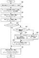
図7は、本発明の実施の形態1における絶対圧補正を実現するために、ECU40が実行するルーチンを示すフローチャートである。尚、本ルーチンは、内燃機関10のサイクル毎に気筒単位で繰り返し実行されるものとする。
図7に示すルーチンでは、ECU40は、先ず、筒内圧センサ30の出力値(AD変換値)の波形を用いて、当該出力値が最大となる時のクランク角度である筒内圧最大クランク角度θPmaxを取得する(ステップ100)。
次に、ECU40は、取得した筒内圧最大クランク角度θPmaxからパラメータαを引くことにより得られる値を第2クランク角度θ2として算出する(ステップ102)。パラメータαは図4を参照して既述した手法に従って予め適合された固定値である。本ステップ102の処理によれば、筒内圧最大クランク角度θPmaxに対してパラメータαだけ進角したクランク角度が第2クランク角度θ2として算出されることになる。
次に、ECU40は、算出した第2クランク角度θ2からクランク角度間隔Δθを引くことにより得られる値を第1クランク角度θ1として算出する(ステップ104)。クランク角度間隔Δθは、図6を参照して既述したように、絶対圧補正値ΔPの精度を確保できるような大きさ(例えば、30°CA)として予め設定された値である。本ステップ104の処理によれば、第2クランク角度θ2に対してクランク角度間隔Δθだけ進角したクランク角度が第1クランク角度θ1として算出されることになる。
次に、ECU40は、上記のように算出した第2クランク角度θ2と第1クランク角度θ1とを用いて、上記(1)式に従って絶対圧補正値ΔPを算出する(ステップ106)。
図8は、本発明の実施の形態1の絶対圧補正手法を適用しつつ、筒内圧センサ30の検出値へのノイズ重畳の影響をシミュレーションした結果を表した図である。より具体的には、図8(A)は、ノイズが重畳していない筒内圧波形に対して、上記図2(A)と同等のホワイトノイズを重畳させた図である。図9は、本発明の実施の形態1の絶対圧補正手法による補正後の筒内圧力Pを用いた燃焼解析値(一例として、燃焼重心位置CA50)の算出結果を表した図である。
以上説明した本実施形態の絶対圧補正手法によれば、第2クランク角度θ2が燃焼開始点の近傍のタイミングに設定される。このように設定された第2クランク角度θ2は、圧縮上死点に近いタイミングである。そして、この第2クランク角度θ2に対して上記クランク角度間隔Δθだけ進角したクランク角度が第1クランク角度θ1として設定される。このように設定された第2クランク角度θ2と第1クランク角度θ1とを用いることで、ベースノイズの影響による絶対圧補正値ΔPの誤差を大幅に低減できるようになる。
その結果、図8(B)および図8(C)に示すように、上記手法による絶対圧補正後の筒内圧力Pを利用して算出したパラメータPVκ(発熱量Qの波形も同様)および燃焼質量割合MFBのそれぞれの波形に重畳するノイズを大幅に減少させることが可能となる。更に、図9(A)および図9(B)に示すように、上記手法による絶対圧補正後の筒内圧力Pを利用して算出した燃焼重心位置CA50に重畳するノイズを大幅に減少させることが可能となる。このように、上記手法による絶対圧補正後の筒内圧力Pを利用することで、各種の燃焼解析値を高精度に算出できるようになる。その結果、筒内圧センサ30の検出値をベースとするエンジン制御において燃費およびドライバビリティを狙い通りに制御できるようになる。
また、筒内圧最大クランク角度θPmaxの取得は、予備計算を一切必要としない。すなわち、筒内圧最大クランク角度θPmaxは、例えば、最大値を記憶するピークホールド機能を利用しつつ筒内圧センサ30の出力値(AD変換値)を取得するだけで容易に検出することができる。そして、このように容易に取得可能な筒内圧最大クランク角度θPmaxを基準として、事前に設定したパラメータαだけ進角した第2クランク角度θ2、更には第2クランク角度θ2から所定のクランク角度間隔Δθだけ進角した第1クランク角度θ1を算出しているので、特段の演算処理負荷を要しない。
更に、筒内圧最大クランク角度θPmaxを基準とする上記の第1および第2クランク角度θ1、θ2の算出は、サイクル毎に行われるものであり、これにより、運転条件に依存せずに適切な2点(θ1、θ2)を算出できるようになる。このため、これらの2点(θ1、θ2)の算出のために運転条件毎にマップを持たせておく必要がないため、適合工数の増加も抑制することができる。
更に、ハードウェア面でのノイズ対策をとる場合には、例えば、センサ回路の複雑化(低圧部と高圧部の2系統化もしくは大容量のコンデンサの追加など)、ワイヤハーネスのシールド化、ECU回路の複雑化といったコストアップ要因が考えられる。しかしながら、本実施形態の絶対圧補正手法によれば、そのようなコストアップを招くことなく、ベースノイズの影響による絶対圧補正値ΔPの誤差を低減できるようになる。
以上のように、本実施形態の絶対圧補正手法によれば、コストアップ、適合工数の増加、および演算処理負荷の増大を招くことなく、効果的にノイズ影響を抑えた筒内圧センサ30の検出値の絶対圧補正を行えるようになる。
ところで、上述した実施の形態1においては、筒内圧最大クランク角度θPmaxからパラメータαだけ進角したクランク角度を第2クランク角度θ2として設定し、第2クランク角度θ2からクランク角度間隔Δθだけ進角したクランク角度を第1クランク角度θ1として設定している。しかしながら、本発明における第1および第2クランク角度の設定手法は、上記に限定されるものではない。すなわち、筒内圧最大クランク角度θPmaxから所定クランク角度間隔(本発明における「第3クランク角度間隔」に相当)だけ進角したクランク角度を第1クランク角度θ1として設定したうえで、当該第1クランク角度θ1から上記クランク角度間隔Δθだけ遅角したクランク角度を第2クランク角度θ2として設定してもよい。あるいは、筒内圧最大クランク角度θPmaxから所定クランク角度間隔(便宜上「第4クランク角度間隔」と称する)だけ進角したクランク角度を第1クランク角度θ1として設定し、かつ、筒内圧最大クランク角度θPmaxから第4クランク角度間隔よりも小さな所定クランク角度間隔(便宜上「第5クランク角度間隔」と称する)だけ進角したクランク角度を第2クランク角度θ2として設定してもよい。
また、上述した実施の形態1においては、一例として、図8(A)等に示すように、第2クランク角度θ2が圧縮上死点よりも進角側のクランク角度に設定されており、第1クランク角度θ1が点火時期よりも進角側のクランク角度に設定された例について説明を行った。しかしながら、本発明における第2クランク角度は、点火時期よりも遅角側のタイミングであって燃焼開始点までのタイミングであれば、筒内圧最大クランク角度に応じて任意に設定されてもよいものである。また、本発明における第1クランク角度は、第2クランク角度に対して所定のクランク角度間隔だけ進角したクランク角度となるようであれば、点火時期よりも遅角側のクランク角度に設定されるものであってもよい。
また、上述した実施の形態1においては、筒内の発熱量Qにリニアな相関のあるパラメータPVκを利用した絶対圧補正手法を例に挙げて説明を行った。しかしながら、本発明において断熱圧縮行程中の第1および第2クランク角度を用いて算出する絶対圧補正値は、筒内の発熱量Qを用いて算出されるものであってもよい。尚、発熱量Qは、以下の(2)式により算出可能である。すなわち、発熱量Qは、筒内圧センサ30の検出値を利用して算出可能な筒内の熱発生率dQ/dθをクランク角度θで積分することによって算出することができる。
Q=∫(dQ/dθ)dθ=∫(1/(κ-1)×(VdP/dθ+PκdV/dθ))dθ ・・・(2)
Q=∫(dQ/dθ)dθ=∫(1/(κ-1)×(VdP/dθ+PκdV/dθ))dθ ・・・(2)
尚、上述した実施の形態1においては、ECU40が上記ステップ100の処理を実行することにより前記第1の発明における「取得手段」が実現され、ECU40が上記ステップ102~106の処理を実行することにより前記第1の発明における「絶対圧補正手段」が実現されている。
また、上述した実施の形態1においては、パラメータαが前記第2の発明における「第1クランク角度間隔」に、クランク角度間隔Δθが前記第2の発明における「第2クランク角度間隔」に、それぞれ相当している。
また、上述した実施の形態1においては、パラメータαが前記第2の発明における「第1クランク角度間隔」に、クランク角度間隔Δθが前記第2の発明における「第2クランク角度間隔」に、それぞれ相当している。
実施の形態2.
次に、図10乃至図13を主に参照して本発明の実施の形態2について説明する。
本実施形態のシステムは、図1に示すハードウェア構成を用いて、ECU40に図7に示すルーチンに代えて後述の図13に示すルーチンを実行させることにより実現することができるものである。
次に、図10乃至図13を主に参照して本発明の実施の形態2について説明する。
本実施形態のシステムは、図1に示すハードウェア構成を用いて、ECU40に図7に示すルーチンに代えて後述の図13に示すルーチンを実行させることにより実現することができるものである。
内燃機関10の運転中には、リーン燃焼、大量EGR燃焼、或いは触媒暖機のための遅角燃焼といった燃焼速度が通常燃焼時よりも低い緩慢燃焼が行われる場合がある。このような緩慢燃焼になると、着火時期(燃焼開始点)が遅くなる(着火遅れ期間が長くなる)。また、緩慢燃焼によって着火時期が遅くなると、主燃焼期間(10~90%燃焼期間)も遅くなる。図10は、10~90%燃焼期間(主燃焼期間)と空燃比(A/F)との関係を表した図である。空燃比を例に挙げると、図10に示すように、空燃比が理論空燃比に対してよりリーンになるほど、燃焼速度が遅くなり、10~90%燃焼期間が長くなる。
上記のような緩慢燃焼によって着火遅れ期間および主燃焼期間が変化したにもかかわらず、通常燃焼時の条件(例えば、空燃比は理論空燃比)に対して設定したパラメータαを用いて第2クランク角度θ2を算出することとすると、既に燃焼が開始した後のクランク角度(すなわち、断熱圧縮行程ではない期間中のクランク角度)が第2クランク角度θ2として選択されることになり得る。その結果、絶対圧補正値ΔPに誤差が発生してしまうことが懸念される。
そこで、本実施形態では、着火遅れ期間および主燃焼期間(燃焼速度)の変化に依らずに適切なパラメータαを決定できるようにするために、次の(3)式に従ってサイクル毎にパラメータαを算出するようにした。
α=k×(θPmax-点火時期) ・・・(3)
ただし、上記(3)式における係数kは適合値(正の値)である。
α=k×(θPmax-点火時期) ・・・(3)
ただし、上記(3)式における係数kは適合値(正の値)である。
図11は、パラメータ(θPmax-点火時期)と10~90%燃焼期間との関係を表した図である。図12は、パラメータαとパラメータ(θPmax-点火時期)との関係(すなわち、上記(3)式の傾向)を表した図である。
パラメータ(θPmax-点火時期)は、点火(放電)してから着火する(燃焼が開始する)までの着火遅れ期間と、その後の主燃焼期間(10~90%燃焼期間)とを含む期間として定義されたものである。このため、図11に示すように、パラメータ(θPmax-点火時期)は、10~90%燃焼期間と相関を有していることが分かる。そして、上記図10および図11に示す関係より、パラメータ(θPmax-点火時期)についても、着火遅れ期間および主燃焼期間に影響を及ぼすパラメータである空燃比と相関があることが分かる。ここでは詳細な説明を省略するが、パラメータ(θPmax-点火時期)は、空燃比以外のEGRガス量および吸気バルブタイミング等の着火遅れ期間および主燃焼期間に影響を及ぼすパラメータに対しても、空燃比と同様に相関があるといえる。そこで、本実施形態では、図12に示すように、上記(3)式の関係を用いて、パラメータ(θPmax-点火時期)が大きくなるほど、第2クランク角度θ2を決定するためのパラメータαを大きくするようにした。
図12に示す関係によれば、例えば、空燃比を通常燃焼時(理論空燃比)よりもリーンとした緩慢燃焼が行われている場合には、パラメータ(θPmax-点火時期)が通常燃焼時よりも長くなる。それに伴い、パラメータαは、通常燃焼時よりも大きな値に設定されることになる。より具体的には、空燃比が理論空燃比に対してリーンになるほど、パラメータが大きくなる。このように、図12に示す関係を用いてパラメータαを決定するようにすることで、空燃比、EGRガス量および吸気バルブタイミング等の着火遅れ期間および主燃焼期間に影響を及ぼすパラメータを求める必要なしに、それらのパラメータの影響を反映し、かつ、現在の燃焼に適したパラメータαをサイクル毎に算出できるようになる。
その結果、リーン燃焼等の緩慢燃焼の実施によって着火遅れ期間および主燃焼期間が変化する場合であっても、確実に断熱圧縮行程中のクランク角度となるように第2クランク角度θ2を設定することができ、上述した実施の形態1と比べ、絶対圧補正値ΔPの算出精度を高めることができる。また、このようにして算出されるパラメータαはすべての運転条件に対して適用可能であり、着火遅れ期間および主燃焼期間に応じた適切なパラメータαを決定することに際して、適合工数が増加するのを回避することができる。
また、上述した手法では、パラメータαの算出に際して、10~90%燃焼期間ではなく、パラメータ(θPmax-点火時期)を利用するようにしている。10~90%燃焼期間は、筒内圧センサ30の検出値を用いて燃焼質量割合MFBを算出したうえで算出する値であるので、精度の良い値を得るには、絶対圧補正が行われた後の筒内圧力Pの値を用いる必要があるものである。したがって、絶対圧補正に用いるパラメータαの算出のために、絶対圧補正がなされていない状態での10~90%燃焼期間を用いることは適切ではない。これに対し、本実施形態では、絶対圧補正の実行の有無の影響を受けないパラメータ(θPmax-点火時期)に基づいてパラメータαを適切に算出できるようになる。また、パラメータ(θPmax-点火時期)は、実施の形態1において既述したように、ピークホールド機能などを用いて取得の容易な筒内圧最大クランク角度θPmaxを点火時期とともに用いるものである。このため、演算処理負荷の増大を招くことなく、着火遅れ期間および主燃焼期間に応じたパラメータαをサイクル毎に算出できるようになる。
図13は、本発明の実施の形態2における絶対圧補正を実現するために、ECU40が実行するルーチンを示すフローチャートである。尚、図13において、実施の形態1における図7に示すステップと同一のステップについては、同一の符号を付してその説明を省略または簡略する。
図13に示すルーチンでは、ECU40は、ステップ100において筒内圧最大クランク角度θPmaxを算出した後に、上記(3)式に従って、パラメータ(θPmax-点火時期)に基づいてパラメータαを算出する(ステップ200)。尚、本実施形態では、上記(3)式中の係数kとしては、事前に設定しておいた適合値が用いられる。
以上説明した図13に示すルーチンによれば、上述したように、適合工数の増加および演算処理負荷の増大を招くことなく、着火遅れ期間および主燃焼期間に応じたパラメータαをサイクル毎に算出できるようになる。
実施の形態3.
次に、図14および図15を主に参照して本発明の実施の形態3について説明する。
本実施形態のシステムは、図1に示すハードウェア構成を用いて、ECU40に図13に示すルーチンに代えて後述の図15に示すルーチンを実行させることにより実現することができるものである。
次に、図14および図15を主に参照して本発明の実施の形態3について説明する。
本実施形態のシステムは、図1に示すハードウェア構成を用いて、ECU40に図13に示すルーチンに代えて後述の図15に示すルーチンを実行させることにより実現することができるものである。
図14は、吸入空気量が少ない状況下での燃焼時における第1クランク角度θ1の設定手法を説明するための図である。
吸入空気量が少ない状況下、すなわち、低負荷運転時には、圧縮行程において筒内圧力Pが上昇しにくくなる。その結果、クランク角度間隔Δθを上記図6を参照して既述した思想に基づいて設定した場合に、第1クランク角度θ1での筒内圧力P(θ1)が低すぎてしまうことがある。筒内圧力P(θ1)が低いと、この筒内圧力P(θ1)がノイズの影響を受け易くなる。このため、絶対圧補正値ΔPの誤差が大きくなってしまうことが懸念される。
吸入空気量が少ない状況下、すなわち、低負荷運転時には、圧縮行程において筒内圧力Pが上昇しにくくなる。その結果、クランク角度間隔Δθを上記図6を参照して既述した思想に基づいて設定した場合に、第1クランク角度θ1での筒内圧力P(θ1)が低すぎてしまうことがある。筒内圧力P(θ1)が低いと、この筒内圧力P(θ1)がノイズの影響を受け易くなる。このため、絶対圧補正値ΔPの誤差が大きくなってしまうことが懸念される。
そこで、本実施形態では、第1クランク角度θ1を算出する際に、第2クランク角度θ2からクランク角度間隔Δθを引いて得た第1クランク角度θ1での筒内圧力P(θ1)が所定の判定値Pmin(例えば、0.4MPa)以下となるような場合には、図14に示すように、判定値Pminよりも筒内圧力Pが若干高くなるタイミングでのクランク角度が第1クランク角度θ1となるようにするためのクランク角度間隔の修正値Δθ’を算出するようにした。
更に、本実施形態では、上記のようにクランク角度間隔ΔθをΔθ’に修正する処理を行った場合には、この処理を行った際の運転条件(主に吸入空気量)をΔθ’と関連付けて学習することとした。そして、次回以降のサイクルで同一運転条件になった際には、上記修正後のクランク角度間隔Δθ’を取得して第1クランク角度θ1を算出するようにした。
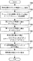
図15は、本発明の実施の形態3における絶対圧補正を実現するために、ECU40が実行するルーチンを示すフローチャートである。尚、図15において、実施の形態2における図13に示すステップと同一のステップについては、同一の符号を付してその説明を省略または簡略する。
図15に示すルーチンでは、ECU40は、ステップ104において第1クランク角度θ1を算出した後に、第1クランク角度θ1での筒内圧力P(θ1)が上記判定値Pminよりも高いか否かを判定する(ステップ300)。その結果、本ステップ300の判定が成立する場合には、ECU40は、直ちにステップ106に進んで絶対圧補正値ΔPを算出する。
一方、上記ステップ300の判定が不成立である場合、つまり、筒内圧力P(θ1)が低すぎることで絶対圧補正値ΔPの誤差が大きくなることが懸念される場合には、ECU40は、今回の処理サイクルでの運転条件と同じ運転条件(主に吸入空気量(負荷率KL)条件)において学習が済んでいるか否かを判定する(ステップ302)。
その結果、上記学習が未だ行われていない運転条件である場合には、ECU40は、判定値Pminよりも筒内圧力Pが若干高くなるタイミングでのクランク角度が第1クランク角度θ1となるようにするためのクランク角度間隔の修正値Δθ’を算出し、修正値Δθ’と関連付けて現在の運転条件を学習値として保持する(ステップ304)。この場合には、ECU40は、第2クランク角度θ2から、修正後のクランク角度間隔Δθ’を引くことにより得られる値として第1クランク角度θ1を算出する(ステップ306)。
一方、上記ステップ302において学習が既に行われていると判定された場合には、ECU40は、今回の処理サイクルと同一の運転条件において過去に算出しておいたクランク角度間隔Δθ’を取得し(ステップ308)、ステップ306に進む。
以上説明した図15に示すルーチンによれば、低負荷運転時において第1クランク角度θ1での筒内圧力P(θ1)が判定値Pmin以下となる場合には、判定値Pminよりも筒内圧力Pが若干高くなるタイミングでのクランク角度が第1クランク角度θ1となるように修正される。これにより、第1クランク角度θ1での筒内圧力P(θ1)が低すぎることに起因して絶対圧補正値ΔPの誤差が大きくなるのを防止することができる。
また、上記ルーチンによれば、クランク角度間隔ΔθをΔθ’に修正する処理を行った場合には、この処理を行った際の運転条件を修正値Δθ’と関連付けて学習しておき、次回以降のサイクルで同一運転条件になった際に、上記修正値Δθ’が使用される。これにより、運転条件に応じたクランク角度間隔Δθの修正値Δθ’を事前に適合して備えなくて済むようになる。このため、適合工数の低減を図ることができる。
実施の形態4.
次に、図16を主に参照して本発明の実施の形態4について説明する。
本実施形態のシステムは、図1に示すハードウェア構成を用いて、ECU40に図13に示すルーチンに代えて後述の図16に示すルーチンを実行させることにより実現することができるものである。
次に、図16を主に参照して本発明の実施の形態4について説明する。
本実施形態のシステムは、図1に示すハードウェア構成を用いて、ECU40に図13に示すルーチンに代えて後述の図16に示すルーチンを実行させることにより実現することができるものである。
任意のクランク角度θにおける燃焼質量割合MFBは、筒内の発熱量Qに相関のあるパラメータPVκを用いて、次の(4)式に従って算出することができる。
MFB=(PVκ(θ)-PVκ(θsta))/(PVκ(θfin)-PVκ(θsta)) ・・・(4)
ただし、上記(4)式において、θstaは燃焼開始点(燃焼開始時期)であり、θfinは燃焼終了点(燃焼終了時期)である。尚、燃焼質量割合MFBは、パラメータPVκに代えて、上記(2)式を用いて算出可能な発熱量Qを用いて算出することもできる。
MFB=(PVκ(θ)-PVκ(θsta))/(PVκ(θfin)-PVκ(θsta)) ・・・(4)
ただし、上記(4)式において、θstaは燃焼開始点(燃焼開始時期)であり、θfinは燃焼終了点(燃焼終了時期)である。尚、燃焼質量割合MFBは、パラメータPVκに代えて、上記(2)式を用いて算出可能な発熱量Qを用いて算出することもできる。
従来において燃焼質量割合MFBを算出する際には、演算処理の簡素化のために、絶対圧補正値ΔPの算出に関する課題として図2(A)中に黒丸印で表して既述したものと同様に、圧縮上死点から離れたクランク角度を燃焼開始点θstaとして用いることが一般的であった。
上述した実施の形態1等における絶対圧補正手法による補正後の筒内圧力Pを用いることで、図8(B)と図2(B)とを比較して分かるように、ベースノイズの影響が大きく低減されたパラメータPVκの波形を得られるようになる。しかしながら、図8(B)を見て分かるように、圧縮上死点から大きく離れたクランク角度では、ベースノイズの影響がパラメータPVκの波形に少ないレベルではあるが残っている。したがって、実施の形態1等における絶対圧補正手法による補正後の筒内圧力Pを基礎としてパラメータPVκ(
発熱量Qを使う場合も同様)を算出して燃焼質量割合MFBを算出する場合に、従来の手法のような圧縮上死点から大きく離れたクランク角度を燃焼開始点θstaとして用いることは、燃焼質量割合MFBの算出における精度の悪化要因となってしまう。
発熱量Qを使う場合も同様)を算出して燃焼質量割合MFBを算出する場合に、従来の手法のような圧縮上死点から大きく離れたクランク角度を燃焼開始点θstaとして用いることは、燃焼質量割合MFBの算出における精度の悪化要因となってしまう。
そこで、本実施形態では、実施の形態1等における絶対圧補正手法による補正後の筒内圧力Pを用いて燃焼質量割合MFBを算出する場合に、筒内圧最大クランク角度θPmaxからパラメータαだけ進角したクランク角度として算出される上記第2クランク角度θ2を燃焼開始点θstaとして用いるようにした。
図16は、本発明の実施の形態4における燃焼質量割合MFBの演算を実現するために、ECU40が実行するルーチンを示すフローチャートである。尚、図16において、実施の形態2における図13に示すステップと同一のステップについては、同一の符号を付してその説明を省略または簡略する。ここでは、実施の形態2で説明した絶対圧補正手法と組み合わせることとしているが、本実施形態の燃焼質量割合MFBの算出処理は、他の実施の形態1または3で説明した絶対圧補正手法と組み合わせて実行されるものであってもよい。
図16に示すルーチンでは、ECU40は、ステップ106において絶対圧補正値ΔPを算出した後に、上記(4)式で用いる燃焼開始点θstaとして上記ステップ102において算出した第2クランク角度θ2を設定したうえで、当該(4)式に従って燃焼質量割合MFBを算出する(ステップ400)。尚、上記(4)式中の燃焼終了点θfinは、絶対圧補正後の筒内圧力Pを用いて算出するパラメータPVκが最大値に達した時のクランク角度として取得することができる。ECU40は、次いで、燃焼質量割合MFBの算出値を利用して得られる燃焼解析値として、燃焼重心位置CA50を算出する(ステップ402)。
以上説明した図16に示すルーチンによれば、筒内圧最大クランク角度θPmaxを基準として算出した第2クランク角度θ2を燃焼開始点θstaとして用いて燃焼質量割合MFBを算出することにより、燃焼開始点θstaでの発熱量相関値であるPVκ(θsta)に与えるベースノイズの影響を低減することができる。このように、ベースノイズの影響を大きく低減した絶対圧補正値ΔPを用い、かつ、上記第2クランク角度θ2を燃焼開始点θstaとして用いることにより、燃焼質量割合MFBの算出精度を更に向上させることができる。
尚、上述した実施の形態4においては、ECU40が上記ステップ400の処理を実行することにより前記第7の発明における「燃焼質量割合算出手段」が実現されている。
10 内燃機関
12 ピストン
14 燃焼室
16 吸気通路
18 排気通路
20 吸気弁
22 排気弁
24 スロットルバルブ
26 燃料噴射弁
28 点火プラグ
30 筒内圧センサ
40 ECU(Electronic Control Unit)
42 クランク角センサ
12 ピストン
14 燃焼室
16 吸気通路
18 排気通路
20 吸気弁
22 排気弁
24 スロットルバルブ
26 燃料噴射弁
28 点火プラグ
30 筒内圧センサ
40 ECU(Electronic Control Unit)
42 クランク角センサ
Claims (7)
- 筒内圧力を検出する筒内圧センサと、
燃焼期間中に前記筒内圧センサにより検出される筒内圧力が最大となる筒内圧最大クランク角度を取得する取得手段と、
前記筒内圧最大クランク角度を基準として、吸気弁が閉じてから燃焼が開始するまでの断熱圧縮行程において第1クランク角度と当該第1クランク角度よりも遅角側の第2クランク角度とを設定し、前記第1クランク角度および前記第2クランク角度でのそれぞれの筒内圧力と筒内容積とを用いて、前記筒内圧センサにより検出される筒内圧力の絶対圧補正を実行する絶対圧補正手段と、
を備え、
前記絶対圧補正手段は、点火時期より遅角側の断熱圧縮行程中のタイミングとなるように前記筒内圧最大クランク角度に対して進角したクランク角度を前記第2クランク角度として設定して前記絶対圧補正に用いることを特徴とする内燃機関の制御装置。 - 前記絶対圧補正手段は、前記筒内圧最大クランク角度に対して第1クランク角度間隔だけ進角したクランク角度を前記第2クランク角度として設定し、前記第2クランク角度に対して第2クランク角度間隔だけ進角したクランク角度を前記第1クランク角度として設定することを特徴とする請求項1に記載の内燃機関の制御装置。
- 前記絶対圧補正手段は、前記筒内圧最大クランク角度に対して第3クランク角度間隔だけ進角したクランク角度を前記第1クランク角度として設定し、前記第1クランク角度に対して第2クランク角度間隔だけ遅角したクランク角度を前記第2クランク角度として設定することを特徴とする請求項1に記載の内燃機関の制御装置。
- 前記絶対圧補正手段は、前記筒内圧最大クランク角度と点火時期との差に基づいて前記第1クランク角度間隔を設定することを特徴とする請求項2に記載の内燃機関の制御装置。
- 前記絶対圧補正手段は、前記第2クランク角度として、燃焼開始点近傍のクランク角度を設定することを特徴とする請求項1~4の何れか1つに記載の内燃機関の制御装置。
- 前記絶対圧補正手段は、前記第1クランク角度を、所定値よりも高い筒内圧力でのクランク角度に設定することを特徴とする請求項1~5の何れか1つに記載の内燃機関の制御装置。
- 前記絶対圧補正手段による補正後の筒内圧力を用い、かつ、前記第2クランク角度を燃焼開始点として用いて、燃焼質量割合を算出する燃焼質量割合算出手段を更に備えることを特徴とする請求項1~6の何れか1つに記載の内燃機関の制御装置。
Priority Applications (3)
| Application Number | Priority Date | Filing Date | Title |
|---|---|---|---|
| CN201480002999.1A CN104781528B (zh) | 2013-01-24 | 2014-01-17 | 内燃机的控制装置 |
| US14/441,258 US9765709B2 (en) | 2013-01-24 | 2014-01-17 | Control apparatus for determining an absolute pressure correction in an internal combustion engine |
| EP14743416.1A EP2949909B1 (en) | 2013-01-24 | 2014-01-17 | Device for controlling internal combustion engine |
Applications Claiming Priority (2)
| Application Number | Priority Date | Filing Date | Title |
|---|---|---|---|
| JP2013-010951 | 2013-01-24 | ||
| JP2013010951A JP5708674B2 (ja) | 2013-01-24 | 2013-01-24 | 内燃機関の制御装置 |
Publications (1)
| Publication Number | Publication Date |
|---|---|
| WO2014115654A1 true WO2014115654A1 (ja) | 2014-07-31 |
Family
ID=51227446
Family Applications (1)
| Application Number | Title | Priority Date | Filing Date |
|---|---|---|---|
| PCT/JP2014/050806 Ceased WO2014115654A1 (ja) | 2013-01-24 | 2014-01-17 | 内燃機関の制御装置 |
Country Status (5)
| Country | Link |
|---|---|
| US (1) | US9765709B2 (ja) |
| EP (1) | EP2949909B1 (ja) |
| JP (1) | JP5708674B2 (ja) |
| CN (1) | CN104781528B (ja) |
| WO (1) | WO2014115654A1 (ja) |
Cited By (2)
| Publication number | Priority date | Publication date | Assignee | Title |
|---|---|---|---|---|
| EP3115585A1 (en) * | 2015-07-08 | 2017-01-11 | Toyota Jidosha Kabushiki Kaisha | Control apparatus for internal combustion engine |
| EP3124775A1 (en) * | 2015-07-28 | 2017-02-01 | Toyota Jidosha Kabushiki Kaisha | Control apparatus for internal combustion engine |
Families Citing this family (9)
| Publication number | Priority date | Publication date | Assignee | Title |
|---|---|---|---|---|
| JP5758862B2 (ja) * | 2012-10-16 | 2015-08-05 | トヨタ自動車株式会社 | 内燃機関の筒内圧検出装置 |
| AT516669B1 (de) * | 2014-11-24 | 2016-08-15 | Ge Jenbacher Gmbh & Co Og | Verfahren zur Steuerung einer Brennkraftmaschine |
| EP3283748B1 (en) | 2015-04-14 | 2023-07-26 | Woodward, Inc. | Combustion pressure feedback based engine control with variable resolution sampling windows |
| JP2017025777A (ja) * | 2015-07-22 | 2017-02-02 | トヨタ自動車株式会社 | 内燃機関の制御装置 |
| DE102019207252B4 (de) * | 2018-11-14 | 2024-09-12 | Vitesco Technologies GmbH | Erfassung von zylinderindividuellen Brennverlaufsparameterwerten für einen Verbrennungsmotor |
| US10934965B2 (en) | 2019-04-05 | 2021-03-02 | Woodward, Inc. | Auto-ignition control in a combustion engine |
| JP7431512B2 (ja) * | 2019-05-23 | 2024-02-15 | 日立Astemo株式会社 | 内燃機関制御装置 |
| EP3974639B1 (en) * | 2019-08-02 | 2025-03-19 | Mitsubishi Heavy Industries Engine & Turbocharger, Ltd. | Internal combustion engine and power generation system |
| CN115405418B (zh) * | 2022-08-03 | 2023-06-06 | 东风汽车集团股份有限公司 | 发动机气流噪声的解析方法、装置、设备及可读存储介质 |
Citations (6)
| Publication number | Priority date | Publication date | Assignee | Title |
|---|---|---|---|---|
| JP2007146785A (ja) * | 2005-11-29 | 2007-06-14 | Toyota Motor Corp | 内燃機関の制御装置および制御方法 |
| JP2009275573A (ja) | 2008-05-14 | 2009-11-26 | Toyota Motor Corp | 内燃機関の制御装置 |
| JP2010174706A (ja) | 2009-01-28 | 2010-08-12 | Toyota Motor Corp | 内燃機関の制御装置 |
| JP2012063363A (ja) | 2004-05-12 | 2012-03-29 | Seiko Epson Corp | 圧力センサー |
| WO2012063363A1 (ja) * | 2010-11-12 | 2012-05-18 | トヨタ自動車株式会社 | 内燃機関の制御装置 |
| JP2012207656A (ja) * | 2011-03-16 | 2012-10-25 | Toyota Motor Corp | 内燃機関の制御装置 |
Family Cites Families (10)
| Publication number | Priority date | Publication date | Assignee | Title |
|---|---|---|---|---|
| JPH05163997A (ja) * | 1991-12-10 | 1993-06-29 | Mitsubishi Electric Corp | 内燃機関制御装置及び方法 |
| GB0112338D0 (en) * | 2001-05-21 | 2001-07-11 | Ricardo Consulting Eng | Improved engine management |
| JP4404030B2 (ja) * | 2004-10-07 | 2010-01-27 | トヨタ自動車株式会社 | 内燃機関の制御装置および制御方法 |
| JP4353078B2 (ja) * | 2004-11-18 | 2009-10-28 | トヨタ自動車株式会社 | 内燃機関の制御装置および制御方法 |
| JP2007291959A (ja) * | 2006-04-25 | 2007-11-08 | Honda Motor Co Ltd | 内燃機関の制御装置 |
| JP4793488B2 (ja) * | 2009-03-11 | 2011-10-12 | トヨタ自動車株式会社 | 内燃機関の制御装置 |
| JP5381755B2 (ja) | 2010-01-29 | 2014-01-08 | トヨタ自動車株式会社 | 筒内圧センサの出力補正装置 |
| US8831856B2 (en) * | 2010-04-19 | 2014-09-09 | Toyota Jidosha Kabushiki Kaisha | Control apparatus for internal combustion engine using estimated quantity of heat generated |
| CN102822487B (zh) * | 2010-11-12 | 2014-09-24 | 丰田自动车株式会社 | 内燃机的控制装置 |
| AT513139B1 (de) * | 2012-08-17 | 2014-02-15 | Ge Jenbacher Gmbh & Co Og | Verfahren zum Betreiben einer Brennkraftmaschine |
-
2013
- 2013-01-24 JP JP2013010951A patent/JP5708674B2/ja not_active Expired - Fee Related
-
2014
- 2014-01-17 WO PCT/JP2014/050806 patent/WO2014115654A1/ja not_active Ceased
- 2014-01-17 CN CN201480002999.1A patent/CN104781528B/zh not_active Expired - Fee Related
- 2014-01-17 US US14/441,258 patent/US9765709B2/en not_active Expired - Fee Related
- 2014-01-17 EP EP14743416.1A patent/EP2949909B1/en not_active Not-in-force
Patent Citations (6)
| Publication number | Priority date | Publication date | Assignee | Title |
|---|---|---|---|---|
| JP2012063363A (ja) | 2004-05-12 | 2012-03-29 | Seiko Epson Corp | 圧力センサー |
| JP2007146785A (ja) * | 2005-11-29 | 2007-06-14 | Toyota Motor Corp | 内燃機関の制御装置および制御方法 |
| JP2009275573A (ja) | 2008-05-14 | 2009-11-26 | Toyota Motor Corp | 内燃機関の制御装置 |
| JP2010174706A (ja) | 2009-01-28 | 2010-08-12 | Toyota Motor Corp | 内燃機関の制御装置 |
| WO2012063363A1 (ja) * | 2010-11-12 | 2012-05-18 | トヨタ自動車株式会社 | 内燃機関の制御装置 |
| JP2012207656A (ja) * | 2011-03-16 | 2012-10-25 | Toyota Motor Corp | 内燃機関の制御装置 |
Non-Patent Citations (1)
| Title |
|---|
| See also references of EP2949909A4 * |
Cited By (2)
| Publication number | Priority date | Publication date | Assignee | Title |
|---|---|---|---|---|
| EP3115585A1 (en) * | 2015-07-08 | 2017-01-11 | Toyota Jidosha Kabushiki Kaisha | Control apparatus for internal combustion engine |
| EP3124775A1 (en) * | 2015-07-28 | 2017-02-01 | Toyota Jidosha Kabushiki Kaisha | Control apparatus for internal combustion engine |
Also Published As
| Publication number | Publication date |
|---|---|
| US9765709B2 (en) | 2017-09-19 |
| JP2014141931A (ja) | 2014-08-07 |
| EP2949909A1 (en) | 2015-12-02 |
| EP2949909B1 (en) | 2021-03-17 |
| US20150315993A1 (en) | 2015-11-05 |
| CN104781528B (zh) | 2017-03-22 |
| CN104781528A (zh) | 2015-07-15 |
| EP2949909A4 (en) | 2016-01-27 |
| JP5708674B2 (ja) | 2015-04-30 |
Similar Documents
| Publication | Publication Date | Title |
|---|---|---|
| JP5708674B2 (ja) | 内燃機関の制御装置 | |
| JP4625111B2 (ja) | 内燃機関の燃料制御装置 | |
| CN106337750B (zh) | 内燃机的控制装置 | |
| CN106337743B (zh) | 内燃机的控制装置 | |
| JP6447434B2 (ja) | 燃料噴射制御装置 | |
| US20150226642A1 (en) | In-cylinder pressure detection device for internal combustion engine | |
| JP2008202460A (ja) | 内燃機関の制御装置 | |
| US9903302B2 (en) | Control device for internal combustion engine | |
| JP6359594B2 (ja) | 内燃機関の制御装置 | |
| JP3854209B2 (ja) | 内燃機関の燃料噴射制御装置 | |
| US10087867B2 (en) | Control device for internal combustion engine | |
| US10808630B2 (en) | Control device for internal combustion engine | |
| JP2016125363A (ja) | 内燃機関の制御装置 | |
| US8578909B2 (en) | Control device for internal combustion engine | |
| JP2005054753A (ja) | 内燃機関の燃料噴射制御装置 | |
| JP6456256B2 (ja) | 内燃機関の制御装置 | |
| JP2012207656A (ja) | 内燃機関の制御装置 | |
| JP5772531B2 (ja) | 内燃機関の制御装置 | |
| JP2012077729A (ja) | 筒内圧センサの異常判定装置 | |
| JP2017141705A (ja) | 内燃機関の燃料噴射制御装置 | |
| JP6456273B2 (ja) | 内燃機関の制御装置 | |
| JP6456272B2 (ja) | 内燃機関の制御装置 | |
| JP2010229928A (ja) | 内燃機関の点火時期制御装置 | |
| JP2013133801A (ja) | 内燃機関の制御装置 | |
| JP2010229861A (ja) | 内燃機関の点火時期制御装置 |
Legal Events
| Date | Code | Title | Description |
|---|---|---|---|
| 121 | Ep: the epo has been informed by wipo that ep was designated in this application |
Ref document number: 14743416 Country of ref document: EP Kind code of ref document: A1 |
|
| WWE | Wipo information: entry into national phase |
Ref document number: 14441258 Country of ref document: US |
|
| WWE | Wipo information: entry into national phase |
Ref document number: 2014743416 Country of ref document: EP |
|
| NENP | Non-entry into the national phase |
Ref country code: DE |