WO2014115704A1 - Dispositif d'exposition à un chauffage par micro-ondes - Google Patents
Dispositif d'exposition à un chauffage par micro-ondes Download PDFInfo
- Publication number
- WO2014115704A1 WO2014115704A1 PCT/JP2014/051063 JP2014051063W WO2014115704A1 WO 2014115704 A1 WO2014115704 A1 WO 2014115704A1 JP 2014051063 W JP2014051063 W JP 2014051063W WO 2014115704 A1 WO2014115704 A1 WO 2014115704A1
- Authority
- WO
- WIPO (PCT)
- Prior art keywords
- microwave heating
- primary radiator
- irradiation apparatus
- reflecting mirror
- sample stage
- Prior art date
- Legal status (The legal status is an assumption and is not a legal conclusion. Google has not performed a legal analysis and makes no representation as to the accuracy of the status listed.)
- Ceased
Links
Images


Classifications
-
- H—ELECTRICITY
- H01—ELECTRIC ELEMENTS
- H01Q—ANTENNAS, i.e. RADIO AERIALS
- H01Q19/00—Combinations of primary active antenna elements and units with secondary devices, e.g. with quasi-optical devices, for giving the antenna a desired directional characteristic
- H01Q19/10—Combinations of primary active antenna elements and units with secondary devices, e.g. with quasi-optical devices, for giving the antenna a desired directional characteristic using reflecting surfaces
- H01Q19/12—Combinations of primary active antenna elements and units with secondary devices, e.g. with quasi-optical devices, for giving the antenna a desired directional characteristic using reflecting surfaces wherein the surfaces are concave
- H01Q19/17—Combinations of primary active antenna elements and units with secondary devices, e.g. with quasi-optical devices, for giving the antenna a desired directional characteristic using reflecting surfaces wherein the surfaces are concave the primary radiating source comprising two or more radiating elements
-
- F—MECHANICAL ENGINEERING; LIGHTING; HEATING; WEAPONS; BLASTING
- F27—FURNACES; KILNS; OVENS; RETORTS
- F27B—FURNACES, KILNS, OVENS OR RETORTS IN GENERAL; OPEN SINTERING OR LIKE APPARATUS
- F27B17/00—Furnaces of a kind not covered by any of groups F27B1/00 - F27B15/00
- F27B17/02—Furnaces of a kind not covered by any of groups F27B1/00 - F27B15/00 specially designed for laboratory use
-
- F—MECHANICAL ENGINEERING; LIGHTING; HEATING; WEAPONS; BLASTING
- F27—FURNACES; KILNS; OVENS; RETORTS
- F27D—DETAILS OR ACCESSORIES OF FURNACES, KILNS, OVENS OR RETORTS, IN SO FAR AS THEY ARE OF KINDS OCCURRING IN MORE THAN ONE KIND OF FURNACE
- F27D11/00—Arrangement of elements for electric heating in or on furnaces
- F27D11/12—Arrangement of elements for electric heating in or on furnaces with electromagnetic fields acting directly on the material being heated
-
- H—ELECTRICITY
- H01—ELECTRIC ELEMENTS
- H01Q—ANTENNAS, i.e. RADIO AERIALS
- H01Q17/00—Devices for absorbing waves radiated from an antenna; Combinations of such devices with active antenna elements or systems
-
- H—ELECTRICITY
- H05—ELECTRIC TECHNIQUES NOT OTHERWISE PROVIDED FOR
- H05B—ELECTRIC HEATING; ELECTRIC LIGHT SOURCES NOT OTHERWISE PROVIDED FOR; CIRCUIT ARRANGEMENTS FOR ELECTRIC LIGHT SOURCES, IN GENERAL
- H05B6/00—Heating by electric, magnetic or electromagnetic fields
- H05B6/64—Heating using microwaves
- H05B6/70—Feed lines
-
- H—ELECTRICITY
- H05—ELECTRIC TECHNIQUES NOT OTHERWISE PROVIDED FOR
- H05B—ELECTRIC HEATING; ELECTRIC LIGHT SOURCES NOT OTHERWISE PROVIDED FOR; CIRCUIT ARRANGEMENTS FOR ELECTRIC LIGHT SOURCES, IN GENERAL
- H05B6/00—Heating by electric, magnetic or electromagnetic fields
- H05B6/64—Heating using microwaves
- H05B6/80—Apparatus for specific applications
Definitions
- the present invention relates to a heating device using a microwave, and can be applied, for example, in the steelmaking field.
- Patent Document 1 relates to a microwave iron furnace, and discloses a configuration for realizing the microwave iron furnace.
- Non-Patent Document 1 discloses a conceptual configuration when a phased array antenna is used as a microwave irradiation source and this is applied to a microwave iron making system as one of industrial applicators.
- Patent Document 1 and Non-Patent Document 1 although there is a description of a microwave irradiation source, a material that reflects the microwave, and an image of a reflecting mirror, specific examples for efficiently irradiating a sample with microwaves are described.
- the shape of the reflector is not clear.
- the configuration has a plurality of reflecting mirrors, and there is a problem that the apparatus becomes complicated.
- the present invention has been made to solve the above-described problems, and includes a reflector having a shape that efficiently irradiates a sample with microwaves, and the apparatus is simplified by using only one reflector. Another object is to obtain a microwave heating irradiation apparatus.
- a microwave heating irradiation apparatus includes a primary radiator that radiates spherical microwaves, a reflecting mirror that reflects spherical microwaves radiated from the primary radiator, a sample stage on which a sample is disposed, and a sample stage And a reflecting mirror on a central axis passing through the central position of the sample stage with one end passing through the central position of the sample stage and the focal point of the spherical microwave source radiated by the primary radiator and the central position of the sample stage.
- the torus mirror surface is obtained when an elliptic curve in which the line segment connecting the other end and the wave source does not intersect with the central axis is used as the rotational axis.
- the present invention it is possible to obtain a microwave heating irradiation apparatus in which the apparatus is simplified by providing a reflecting mirror having a shape for efficiently irradiating a sample with microwaves, and using only one reflecting mirror.
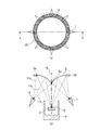
- FIG. 1 is a diagram showing a configuration of a microwave heating irradiation apparatus according to Embodiment 1 of the present invention.
- (A) is a top view of the microwave heating irradiation apparatus, and
- (b) is a cross-sectional view of the AA plane in (a).
- the microwave heating irradiation apparatus includes a primary radiator 1, a reflecting mirror 2, a sample stage 3, and a furnace 4.
- the primary radiator 1 radiates spherical microwaves, and a plurality of primary radiators 1 are arranged around the furnace 4 in an arc shape. You may select suitably the number of arrangement
- the spherical microwave is irradiated with the central position 12 of the primary radiator as a wave source.
- the central position 12 of the primary radiator is directed towards the reflector 2.
- the reflecting mirror 2 reflects the spherical microwave radiated from the primary radiator 1 and converges the microwave on the central portion of the sample table 3, and only one is placed on the sample table 3 and the furnace 4. Is done.
- the sample stage 3 is a stage on which a sample (not shown) to be irradiated with microwaves is placed, and is placed inside the furnace 4.
- a reflecting mirror 2 is disposed on the top of the sample stage 3.
- a straight line passing through the center position 13 of the sample stage is the center axis 14.
- the furnace 4 is a place where the sample is heated by microwaves, and has a shape including a recess opened in the direction of the reflecting mirror 2.
- a primary radiator 1 is disposed around the furnace 4, and a reflecting mirror 2 is disposed above the furnace 4.
- the sample stage 3 is housed inside.
- the cross-sectional shape of the reflecting mirror 2 is an elliptic curve with the central position 12 of the primary radiator as the first focal point and the central position 13 of the sample stage as the second focal point.
- FIG. 1 the elliptic curve on the left side of the central axis 14 and the primary radiator 1 will be described.
- one end point 2 a is set on the central axis 14, and the other end point 2 b is the primary radiator 1.
- the line segment connecting the end point 2b and the center position 12 of the primary radiator is a curve that does not intersect the central axis 14 as appropriate.
- the primary radiator 1 and the elliptic curve of the reflecting surface that is the target of the primary radiator 1 are curves that exist on the same side with respect to the central axis 14. For this reason, among the microwaves radiated from the primary radiator 1 on the left side of the central axis 14, the microwaves that converge at the center position 13 of the sample stage are viewed in the direction of the primary radiator 1 as viewed from the central axis 14, that is, The light is reflected by the mirror surface portion of the reflecting mirror 2 on the left side of the central axis 14 and converges to the center position 13 of the sample stage.
- the elliptical curve of the elliptical curve obtained when the central axis 14 is the rotational axis is the shape of the reflecting mirror 2, and when viewed from the sample stage 3, it has a mountain shape with a sharp center.
- a sample is placed on the sample stage 3 in the furnace 4, and in the primary radiator 1 arranged in a circular arc around the furnace 4, spherical microwaves are radiated from the center position 12 of the primary radiator.
- the radiated spherical microwave is diffused and propagated, and is reflected by the reflecting mirror 2 having an elliptic curve in a cross-sectional shape with the central position 12 of the primary radiator as the first focal point and the central position 13 of the sample stage as the second focal point.
- the reflecting mirror 2 having an elliptic curve in a cross-sectional shape with the central position 12 of the primary radiator as the first focal point and the central position 13 of the sample stage as the second focal point.
- FIG. 1B shows three geometrical optical rays of microwaves 11a, 11b, and 11c emitted from the primary radiator 1 on the left side of the central axis 14.
- Reference numeral 11a denotes a light beam that exits from the primary radiator 1 and is reflected by the central point (end point 2a) of the reflecting mirror 2 toward the central position 13 of the sample stage.
- Reference numeral 11b denotes a light beam that exits from the primary radiator 1 and is reflected by the end point 2b of the reflecting mirror 2 toward the center position 13 of the sample stage.
- Reference numeral 11c denotes a light beam that exits from the primary radiator 1 and is reflected at a point between the center point (end point 2a) and the end point 2b of the reflecting mirror 2 toward the center position 13 of the sample stage.
- FIG. 2 shows the calculation result of the power distribution by the microwave on the sample stage 3 at this time.
- the cross section of the primary radiator which is a spherical microwave source, has the center position 12 as the first focus and the center position 13 of the sample stage as the second focus. Since the microwave is reflected by the reflecting mirror 2 having an elliptic curve, the sample can be efficiently irradiated with the microwave. Further, since the reflecting mirror 2 is composed of one sheet, it is not necessary to provide a plurality of reflecting mirrors, and the apparatus can be simplified.
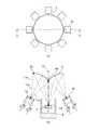
- FIG. FIG. 3 is a diagram showing a configuration of a microwave heating irradiation apparatus according to Embodiment 2 of the present invention.
- (A) is a top view of the microwave heating irradiation apparatus, and
- (b) is a cross-sectional view of the AA plane in (a).
- the same or corresponding parts as those in the microwave heating irradiation apparatus according to Embodiment 1 shown in FIG. 1 are denoted by the same reference numerals, and the description thereof is omitted.
- the line segment connecting the end point not on the center axis 14 and the center position 12 of the primary radiator intersects the center axis 14. This is different from the first embodiment.
- the cross-sectional shape of the reflecting mirror 2 according to Embodiment 2 is an elliptic curve with the central position 12 of the primary radiator as the first focal point and the central position 13 of the sample stage as the second focal point.
- FIG. 3 the elliptical curve on the left side of the central axis 14 and the primary radiator 1 on the right side of the central axis 14 will be described.
- one end point 2a is set on the central axis 14, and the other
- the end point 2b is a curve that is appropriately set according to the radiation property of the primary radiator 1, and a line segment that connects the end point 2b and the center position 12 of the primary radiator is a curve that intersects the central axis 14. .
- the primary radiator 1 and the elliptic curve of the reflecting surface that is the target of the primary radiator 1 are curves that exist on different sides with respect to the central axis 14. For this reason, among the microwaves radiated from the primary radiator 1 on the right side of the central axis 14, the microwaves that converge at the center position 13 of the sample stage are in the direction in which the primary radiator 1 is located as viewed from the central axis 14. Is reflected by the mirror surface portion of the reflecting mirror 2 in the opposite direction, that is, to the left of the central axis 14 and converges to the center position 13 of the sample stage.
- the torus mirror surface obtained when the elliptical curve of the elliptical curve is the rotation axis is the shape of the reflecting mirror 2, and is concave when viewed from the sample stage 3 side.
- the cross section of the primary radiator which is a spherical wave point wave source, has the center position 12 of the primary radiator as the first focus, and the center position 13 of the sample stage as the second focus. Since the microwave is reflected by the reflecting mirror 2 having an elliptic curve, the sample can be efficiently irradiated with the microwave. Further, since the reflecting mirror 2 is composed of one sheet, it is not necessary to provide a plurality of reflecting mirrors, and the apparatus can be simplified.
- FIG. FIG. 4 is a diagram showing a configuration of a microwave heating irradiation apparatus according to Embodiment 3 of the present invention.
- (A) is a top view of the microwave heating irradiation apparatus, and
- (b) is a cross-sectional view of the AA plane in (a).
- the same or corresponding parts as those in the microwave heating irradiation apparatus according to Embodiment 1 shown in FIG. 1 are denoted by the same reference numerals, and the description thereof is omitted.
- the third embodiment is different from the first and second embodiments in that the primary radiator 1 emits a planar microwave and the cross-sectional shape of the reflecting mirror 2 is a parabola.
- the primary radiator 1 according to Embodiment 3 radiates a planar microwave.
- the kind of the primary radiator 1 and the frequency of the microwave to be irradiated may be appropriately selected as described in the first embodiment.
- the cross-sectional shape of the reflecting mirror 2 according to Embodiment 3 is a parabola whose focal point is the center position 13 of the sample stage.
- the torus mirror surface obtained when this parabola is the center axis 14 as the rotation axis is the shape of the reflecting mirror 2.
- the primary radiator 1 radiates a planar microwave, and the microwave is reflected by the reflector 2 whose cross section is a parabola whose focal point is the center position 13 of the sample stage. Since reflection is performed, the sample can be efficiently irradiated with microwaves. Further, since the reflecting mirror 2 is composed of one sheet, it is not necessary to provide a plurality of reflecting mirrors, and the apparatus can be simplified.
- FIG. 4B shows two geometric optical rays of microwaves emitted from the primary radiator 1 as 11b and 11c.
- Reference numeral 11b denotes a light beam that exits from the primary radiator 1 and is reflected at the end point of the reflecting mirror 2 toward the center position 13 of the sample stage.
- Reference numeral 11c denotes a light beam that exits the primary radiator 1 and is reflected at a point other than the end point of the reflecting mirror 2 toward the center position 13 of the sample stage.
- FIG. 5 is a diagram showing a configuration of a microwave heating irradiation apparatus according to Embodiment 4 of the present invention.
- (A) is a top view of the microwave heating irradiation apparatus, and
- (b) is a cross-sectional view of the AA plane in (a).
- the same or corresponding parts as those in the microwave heating irradiation apparatus according to Embodiment 1 shown in FIG. 1 are denoted by the same reference numerals, and the description thereof is omitted.
- the fourth embodiment is different from the other embodiments in that the center portion of the reflecting mirror 2 is provided with a hole 21 for exhaust gas that allows gas generated by a chemical reaction or the like to escape when the sample is heated.
- FIG. 5 shows the case where the configuration according to the fourth embodiment is applied to the first embodiment, but may be applied to the second and third embodiments.
- the exhaust gas-use hole 21 can be provided by determining the end of the reflecting mirror 2 away from the central axis 14 in the cross-sectional shape of the reflecting mirror 2.
- the exhaust gas application hole 21 is provided, in addition to obtaining the same effects as the first to third embodiments, the gas can be exhausted more effectively. An effect is obtained.
- FIG. FIG. 6 is a diagram showing a configuration of a microwave heating irradiation apparatus according to Embodiment 5 of the present invention.
- (A) is a top view of the microwave heating irradiation apparatus, and
- (b) is a cross-sectional view of the AA plane in (a).
- the same or corresponding parts as those in the microwave heating irradiation apparatus according to Embodiment 1 shown in FIG. 1 are denoted by the same reference numerals, and the description thereof is omitted.
- the fifth embodiment is different from the other embodiments in that an absorber 31 is provided around the furnace 4. 6 shows the case where the configuration according to the fifth embodiment is applied to the first embodiment, but the present invention may be applied to the second to fourth embodiments.
- the absorber 31 is provided around the furnace 4 so as to cover the surface of the furnace 4, and has a function of absorbing microwaves.
- the material and characteristics of the absorber used for the absorber 31 may be appropriately selected.
- the absorber 31 is provided around the furnace 4, the same effects as those of the first to third embodiments can be obtained, and a microwave is not necessary. An effect of reducing the influence of radiation can be obtained.
- FIG. 7 is a diagram showing a configuration of a microwave heating irradiation apparatus according to Embodiment 6 of the present invention.
- (A) is a top view of the microwave heating irradiation apparatus, and
- (b) is a cross-sectional view of the AA plane in (a).
- the same or corresponding parts as those in the microwave heating irradiation apparatus according to Embodiment 1 shown in FIG. 1 are denoted by the same reference numerals, and the description thereof is omitted.
- the sixth embodiment is different from the other embodiments in that an absorber 32 is provided around the reflecting mirror 2. 7 shows the case where the configuration according to the sixth embodiment is applied to the first embodiment, but it may be applied to the second to fifth embodiments.
- the absorber 32 is provided around the reflecting mirror 2 along the outer periphery of the reflecting mirror 2 and has a function of absorbing microwaves.
- the material and characteristics of the absorber used for the absorber 32 may be appropriately selected.
- the absorber 32 is provided around the reflecting mirror 2, microwaves leaking from the primary radiator 1 to the outside of the reflecting mirror 2 can be absorbed by the absorber 32.
- the absorber 32 is provided at a location that is not a mirror surface of the reflecting mirror 2. However, in consideration of ease of attachment of the absorber 32, a part of the absorber 32 is appropriately attached to the mirror surface.
- the absorbent body 32 may be provided in a state where it is in a closed state.
- the primary radiator 1 By suppressing the microwave that wraps behind the reflector 2 as seen from the primary radiator 1, the power distribution on the sample stage 3 is disturbed due to multiple reflections caused by unnecessary radiation in the entire apparatus, and the primary radiator 1 It is possible to prevent the failure of the primary radiator 1 due to the microwave returning to the point.
- the absorber 32 is provided around the reflecting mirror 2, the same effects as those of the first to third embodiments can be obtained.
- the effect of reducing the influence of the radiation is obtained.
- FIG. FIG. 8 is a diagram showing a configuration of a microwave heating irradiation apparatus according to Embodiment 7 of the present invention.
- (A) is a top view of the microwave heating irradiation apparatus, and
- (b) is a cross-sectional view of the AA plane in (a).
- the same or corresponding parts as those in the microwave heating irradiation apparatus according to Embodiment 1 shown in FIG. 1 are denoted by the same reference numerals, and the description thereof is omitted.
- the seventh embodiment is different from the other embodiments in that the primary radiator 1 that radiates spherical microwaves is an active phased array antenna 41. 8 shows the case where the configuration according to the seventh embodiment is applied to the first embodiment, but it may be applied to the second to sixth embodiments.
- the active phased array antenna 41 includes an amplifier and a phase shifter for each antenna element or for each subarray antenna composed of a plurality of antenna elements, and appropriately adjusts the amplification amount of each amplifier and the phase shift amount of the phase shifter. It is possible. Therefore, by adjusting the amount of amplification and the amount of phase shift and optimizing each amount of adjustment, the power distribution of the microwave irradiated to the sample stage 3 can be flexibly controlled. The shape of the power distribution and the adjustment amount of the amplification amount and the phase shift amount may be appropriately selected.
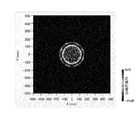
- FIG. 9 shows the calculation result of the power distribution by the microwave on the sample stage 3 when the amplification amount and the phase shift amount are optimized so as to uniformly irradiate a certain region. It is an example which shows the effect of. As shown in FIG. 9, it can be seen that a certain region is uniformly irradiated.
- the primary radiator 1 that radiates microwaves is the active phased array antenna 41.
- the effect of flexibly controlling the power distribution on the sample stage 3 is obtained.
- the microwave heating irradiation apparatus includes a reflector having a shape that efficiently irradiates a sample with microwaves, and the apparatus can be simplified by using a single reflector. Is preferable.
Landscapes
- Engineering & Computer Science (AREA)
- Physics & Mathematics (AREA)
- Electromagnetism (AREA)
- Mechanical Engineering (AREA)
- General Engineering & Computer Science (AREA)
- Health & Medical Sciences (AREA)
- Clinical Laboratory Science (AREA)
- Constitution Of High-Frequency Heating (AREA)
- Aerials With Secondary Devices (AREA)
- Variable-Direction Aerials And Aerial Arrays (AREA)
- Control Of Resistance Heating (AREA)
Abstract
Priority Applications (2)
| Application Number | Priority Date | Filing Date | Title |
|---|---|---|---|
| MYPI2015700816A MY185826A (en) | 2013-01-23 | 2014-01-21 | Microwave heating irradiation device |
| JP2014558569A JP5908127B2 (ja) | 2013-01-23 | 2014-01-21 | マイクロ波加熱照射装置 |
Applications Claiming Priority (2)
| Application Number | Priority Date | Filing Date | Title |
|---|---|---|---|
| JP2013-010184 | 2013-01-23 | ||
| JP2013010184 | 2013-01-23 |
Publications (1)
| Publication Number | Publication Date |
|---|---|
| WO2014115704A1 true WO2014115704A1 (fr) | 2014-07-31 |
Family
ID=51227495
Family Applications (1)
| Application Number | Title | Priority Date | Filing Date |
|---|---|---|---|
| PCT/JP2014/051063 Ceased WO2014115704A1 (fr) | 2013-01-23 | 2014-01-21 | Dispositif d'exposition à un chauffage par micro-ondes |
Country Status (3)
| Country | Link |
|---|---|
| JP (1) | JP5908127B2 (fr) |
| MY (1) | MY185826A (fr) |
| WO (1) | WO2014115704A1 (fr) |
Cited By (2)
| Publication number | Priority date | Publication date | Assignee | Title |
|---|---|---|---|---|
| WO2016009691A1 (fr) * | 2014-07-17 | 2016-01-21 | 三菱電機株式会社 | Chauffage à micro-ondes et dispositif rayonnant |
| WO2016017218A1 (fr) * | 2014-07-29 | 2016-02-04 | 三菱電機株式会社 | Applicateur de micro-ondes |
Citations (5)
| Publication number | Priority date | Publication date | Assignee | Title |
|---|---|---|---|---|
| JPH0397196U (fr) * | 1990-01-25 | 1991-10-04 | ||
| JP2003106773A (ja) * | 2001-09-26 | 2003-04-09 | Micro Denshi Kk | マイクロ波連続加熱装置 |
| JP2003264403A (ja) * | 2002-03-11 | 2003-09-19 | Mitsubishi Electric Corp | マイクロ波移相器 |
| WO2010087464A1 (fr) * | 2009-01-31 | 2010-08-05 | 国立大学法人東京工業大学 | Four de fusion vertical à micro-ondes |
| JP2013011384A (ja) * | 2011-06-29 | 2013-01-17 | Kazuhiro Nagata | マイクロ波加熱炉 |
Family Cites Families (2)
| Publication number | Priority date | Publication date | Assignee | Title |
|---|---|---|---|---|
| JP2006164858A (ja) * | 2004-12-09 | 2006-06-22 | Koito Mfg Co Ltd | 車両用照明灯具 |
| JP2012119121A (ja) * | 2010-11-30 | 2012-06-21 | Stanley Electric Co Ltd | 光源装置および照明装置 |
-
2014
- 2014-01-21 WO PCT/JP2014/051063 patent/WO2014115704A1/fr not_active Ceased
- 2014-01-21 MY MYPI2015700816A patent/MY185826A/en unknown
- 2014-01-21 JP JP2014558569A patent/JP5908127B2/ja active Active
Patent Citations (5)
| Publication number | Priority date | Publication date | Assignee | Title |
|---|---|---|---|---|
| JPH0397196U (fr) * | 1990-01-25 | 1991-10-04 | ||
| JP2003106773A (ja) * | 2001-09-26 | 2003-04-09 | Micro Denshi Kk | マイクロ波連続加熱装置 |
| JP2003264403A (ja) * | 2002-03-11 | 2003-09-19 | Mitsubishi Electric Corp | マイクロ波移相器 |
| WO2010087464A1 (fr) * | 2009-01-31 | 2010-08-05 | 国立大学法人東京工業大学 | Four de fusion vertical à micro-ondes |
| JP2013011384A (ja) * | 2011-06-29 | 2013-01-17 | Kazuhiro Nagata | マイクロ波加熱炉 |
Cited By (6)
| Publication number | Priority date | Publication date | Assignee | Title |
|---|---|---|---|---|
| WO2016009691A1 (fr) * | 2014-07-17 | 2016-01-21 | 三菱電機株式会社 | Chauffage à micro-ondes et dispositif rayonnant |
| JPWO2016009691A1 (ja) * | 2014-07-17 | 2017-04-27 | 三菱電機株式会社 | マイクロ波加熱照射装置 |
| US9823019B2 (en) | 2014-07-17 | 2017-11-21 | Mitsubishi Electric Corporation | Microwave irradiating and heating device |
| WO2016017218A1 (fr) * | 2014-07-29 | 2016-02-04 | 三菱電機株式会社 | Applicateur de micro-ondes |
| JPWO2016017218A1 (ja) * | 2014-07-29 | 2017-04-27 | 三菱電機株式会社 | マイクロ波加熱照射装置 |
| US9737866B2 (en) | 2014-07-29 | 2017-08-22 | Mitsubishi Electric Corporation | Microwave irradiating and heating device |
Also Published As
| Publication number | Publication date |
|---|---|
| JP5908127B2 (ja) | 2016-04-26 |
| MY185826A (en) | 2021-06-11 |
| JPWO2014115704A1 (ja) | 2017-01-26 |
Similar Documents
| Publication | Publication Date | Title |
|---|---|---|
| JP5216107B2 (ja) | 誘電体アンテナ | |
| US3845483A (en) | Antenna system | |
| JP6125106B2 (ja) | マイクロ波加熱照射装置 | |
| JP5908127B2 (ja) | マイクロ波加熱照射装置 | |
| JP2007089391A (ja) | 所定形状を有する反射器を備えた空間放射高出力アンプ | |
| JP6099828B2 (ja) | マイクロ波加熱照射装置 | |
| JP5963976B2 (ja) | マイクロ波加熱照射装置 | |
| CN106654594A (zh) | 太赫兹发射天线系统 | |
| JPWO2014073222A1 (ja) | アレー給電反射鏡アンテナ装置およびその制御方法 | |
| CN105591206A (zh) | 一种毫米波近场机械调焦双反射面天线 | |
| CN206602184U (zh) | 太赫兹发射天线系统 | |
| JP2011504046A5 (fr) | ||
| JP2016170971A (ja) | マイクロ波加熱装置 | |
| JP6586059B2 (ja) | レンズアンテナ装置 | |
| CN118281574A (zh) | 一种毫米波近场低衍射聚焦波束生成方法及系统 | |
| JP4831600B2 (ja) | 高周波加熱装置用直線駆動アンテナ | |
| JPS63173404A (ja) | マルチビ−ムアンテナ | |
| JP6250255B1 (ja) | アンテナ装置 | |
| JPH0473881B2 (fr) | ||
| JP2015201344A (ja) | マイクロ波加熱装置 | |
| JP6397344B2 (ja) | アンテナ装置及び無線システム | |
| JP2007123073A (ja) | 高周波加熱装置 | |
| JP2006173069A (ja) | マイクロ波または電磁波照射装置 | |
| WO2019087418A1 (fr) | Appareil de cuisson | |
| JP2019140510A (ja) | アンテナ校正方法 |
Legal Events
| Date | Code | Title | Description |
|---|---|---|---|
| 121 | Ep: the epo has been informed by wipo that ep was designated in this application |
Ref document number: 14743838 Country of ref document: EP Kind code of ref document: A1 |
|
| ENP | Entry into the national phase |
Ref document number: 2014558569 Country of ref document: JP Kind code of ref document: A |
|
| NENP | Non-entry into the national phase |
Ref country code: DE |
|
| WWE | Wipo information: entry into national phase |
Ref document number: IDP00201505138 Country of ref document: ID |
|
| 122 | Ep: pct application non-entry in european phase |
Ref document number: 14743838 Country of ref document: EP Kind code of ref document: A1 |