WO2014115873A1 - Dispositif de freinage électrique de véhicule - Google Patents
Dispositif de freinage électrique de véhicule Download PDFInfo
- Publication number
- WO2014115873A1 WO2014115873A1 PCT/JP2014/051685 JP2014051685W WO2014115873A1 WO 2014115873 A1 WO2014115873 A1 WO 2014115873A1 JP 2014051685 W JP2014051685 W JP 2014051685W WO 2014115873 A1 WO2014115873 A1 WO 2014115873A1
- Authority
- WO
- WIPO (PCT)
- Prior art keywords
- guide
- axis
- fixed
- guide member
- electric motor
- Prior art date
- Legal status (The legal status is an assumption and is not a legal conclusion. Google has not performed a legal analysis and makes no representation as to the accuracy of the status listed.)
- Ceased
Links
Images




Classifications
-
- F—MECHANICAL ENGINEERING; LIGHTING; HEATING; WEAPONS; BLASTING
- F16—ENGINEERING ELEMENTS AND UNITS; GENERAL MEASURES FOR PRODUCING AND MAINTAINING EFFECTIVE FUNCTIONING OF MACHINES OR INSTALLATIONS; THERMAL INSULATION IN GENERAL
- F16D—COUPLINGS FOR TRANSMITTING ROTATION; CLUTCHES; BRAKES
- F16D55/00—Brakes with substantially-radial braking surfaces pressed together in axial direction, e.g. disc brakes
- F16D55/02—Brakes with substantially-radial braking surfaces pressed together in axial direction, e.g. disc brakes with axially-movable discs or pads pressed against axially-located rotating members
- F16D55/22—Brakes with substantially-radial braking surfaces pressed together in axial direction, e.g. disc brakes with axially-movable discs or pads pressed against axially-located rotating members by clamping an axially-located rotating disc between movable braking members, e.g. movable brake discs or brake pads
- F16D55/224—Brakes with substantially-radial braking surfaces pressed together in axial direction, e.g. disc brakes with axially-movable discs or pads pressed against axially-located rotating members by clamping an axially-located rotating disc between movable braking members, e.g. movable brake discs or brake pads with a common actuating member for the braking members
- F16D55/225—Brakes with substantially-radial braking surfaces pressed together in axial direction, e.g. disc brakes with axially-movable discs or pads pressed against axially-located rotating members by clamping an axially-located rotating disc between movable braking members, e.g. movable brake discs or brake pads with a common actuating member for the braking members the braking members being brake pads
- F16D55/226—Brakes with substantially-radial braking surfaces pressed together in axial direction, e.g. disc brakes with axially-movable discs or pads pressed against axially-located rotating members by clamping an axially-located rotating disc between movable braking members, e.g. movable brake discs or brake pads with a common actuating member for the braking members the braking members being brake pads in which the common actuating member is moved axially, e.g. floating caliper disc brakes
- F16D55/2265—Brakes with substantially-radial braking surfaces pressed together in axial direction, e.g. disc brakes with axially-movable discs or pads pressed against axially-located rotating members by clamping an axially-located rotating disc between movable braking members, e.g. movable brake discs or brake pads with a common actuating member for the braking members the braking members being brake pads in which the common actuating member is moved axially, e.g. floating caliper disc brakes the axial movement being guided by one or more pins engaging bores in the brake support or the brake housing
- F16D55/227—Brakes with substantially-radial braking surfaces pressed together in axial direction, e.g. disc brakes with axially-movable discs or pads pressed against axially-located rotating members by clamping an axially-located rotating disc between movable braking members, e.g. movable brake discs or brake pads with a common actuating member for the braking members the braking members being brake pads in which the common actuating member is moved axially, e.g. floating caliper disc brakes the axial movement being guided by one or more pins engaging bores in the brake support or the brake housing by two or more pins
-
- F—MECHANICAL ENGINEERING; LIGHTING; HEATING; WEAPONS; BLASTING
- F16—ENGINEERING ELEMENTS AND UNITS; GENERAL MEASURES FOR PRODUCING AND MAINTAINING EFFECTIVE FUNCTIONING OF MACHINES OR INSTALLATIONS; THERMAL INSULATION IN GENERAL
- F16D—COUPLINGS FOR TRANSMITTING ROTATION; CLUTCHES; BRAKES
- F16D65/00—Parts or details
- F16D65/14—Actuating mechanisms for brakes; Means for initiating operation at a predetermined position
- F16D65/16—Actuating mechanisms for brakes; Means for initiating operation at a predetermined position arranged in or on the brake
- F16D65/18—Actuating mechanisms for brakes; Means for initiating operation at a predetermined position arranged in or on the brake adapted for drawing members together, e.g. for disc brakes
-
- F—MECHANICAL ENGINEERING; LIGHTING; HEATING; WEAPONS; BLASTING
- F16—ENGINEERING ELEMENTS AND UNITS; GENERAL MEASURES FOR PRODUCING AND MAINTAINING EFFECTIVE FUNCTIONING OF MACHINES OR INSTALLATIONS; THERMAL INSULATION IN GENERAL
- F16D—COUPLINGS FOR TRANSMITTING ROTATION; CLUTCHES; BRAKES
- F16D2121/00—Type of actuator operation force
- F16D2121/18—Electric or magnetic
- F16D2121/24—Electric or magnetic using motors
-
- F—MECHANICAL ENGINEERING; LIGHTING; HEATING; WEAPONS; BLASTING
- F16—ENGINEERING ELEMENTS AND UNITS; GENERAL MEASURES FOR PRODUCING AND MAINTAINING EFFECTIVE FUNCTIONING OF MACHINES OR INSTALLATIONS; THERMAL INSULATION IN GENERAL
- F16D—COUPLINGS FOR TRANSMITTING ROTATION; CLUTCHES; BRAKES
- F16D2125/00—Components of actuators
- F16D2125/18—Mechanical mechanisms
- F16D2125/20—Mechanical mechanisms converting rotation to linear movement or vice versa
- F16D2125/34—Mechanical mechanisms converting rotation to linear movement or vice versa acting in the direction of the axis of rotation
- F16D2125/40—Screw-and-nut
-
- F—MECHANICAL ENGINEERING; LIGHTING; HEATING; WEAPONS; BLASTING
- F16—ENGINEERING ELEMENTS AND UNITS; GENERAL MEASURES FOR PRODUCING AND MAINTAINING EFFECTIVE FUNCTIONING OF MACHINES OR INSTALLATIONS; THERMAL INSULATION IN GENERAL
- F16D—COUPLINGS FOR TRANSMITTING ROTATION; CLUTCHES; BRAKES
- F16D2125/00—Components of actuators
- F16D2125/18—Mechanical mechanisms
- F16D2125/44—Mechanical mechanisms transmitting rotation
- F16D2125/46—Rotating members in mutual engagement
- F16D2125/48—Rotating members in mutual engagement with parallel stationary axes, e.g. spur gears
Definitions
- the present invention relates to an electric braking device for a vehicle.
- Patent Document 1 in a brake device that is electrically driven by a motor, a wiring control device and an actuator, a vehicle motion control device and a thrust sensor, and three bending cables that connect the vehicle motion control device and a wheel speed sensor are wired.
- a communication circuit Installed on the wheel side, power is supplied to the drive control device through the two power lines from the vehicle body side, the braking force signal from the vehicle motion control device is received by multiplex communication, and the motor is driven to control the vehicle. It generates power ".
- the casing installed on the wheel side is fixed to the housing on the side opposite to the disk rotor and the pad in the direction of the linear motion converted by the conversion mechanism, The drive control device is fixed inside the casing.
- a drive control device including electronic components is installed on the wheel side.
- the vibration of the vehicle body (on the spring) is reduced by a shock absorber or the like, but excessive vibration is input to the wheel (under the spring). .
- electronic components are provided under the spring, it is necessary to consider vibrations for these electronic components.
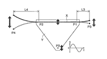
- the amplitude of the point P4 (the distance L4 from the support point P2 is longer than L3) is more likely to be amplified than the point P3 (the distance L3 from the support point P1).
- the acceleration acting on each position is increased, so that an excessive inertial force acts on a member disposed in a place where vibration amplification is likely to occur.
- the brake caliper is attached to a knuckle that supports the wheel via a mounting bracket.
- the degree of vibration degree of vibration from the wheels
- the fastening portion between the caliper and the mounting bracket is a support portion, which is the most advantageous point in terms of vibration. Amplification of vibration tends to occur when the support portion is separated.
- the arrangement of members is optimized and vibration applied to these components is suppressed It is important that
- the present invention has been made to cope with the above-described problems, and an object of the present invention is an electric braking device including an electric motor and a driving circuit on a wheel side, and an electronic component such as a driving circuit is preferable.
- the electronic component can be improved in reliability against vibration from the road surface when the vehicle is traveling.
- Another object of the present invention is to provide an electric braking device in which an electric motor is provided on the wheel side, and electric power is supplied to the electric motor via a connector.
- the electric motor and the connector are suitably arranged, and the vehicle is running.
- An object of the present invention is to provide an electric motor that can improve the reliability of an electric motor and a connector against vibration from a road surface.
- the electric braking device for a vehicle presses the friction member (MSB) to the rotating member (KTB) fixed to the wheel (WHL) of the vehicle via the electric motor (MTR), thereby the wheel (WHL). To generate braking torque.
- This device includes a mount member (MTB) fixed to a support member (NKL) that supports the wheel (WHL), and a first guide member having an axis (Jgd1) fixed to the mount member (MTB). (GD1) and an axis (Jgd2) parallel to the axis (Jgd1) of the first guide member (GD1) fixed to the mount member (MTB) at a position different from the first guide member (GD1). ) Having a second guide member (GD2) and an axial direction (ZH1) of the first and second guide members (GD1, GD2) supported by the first and second guide members (GD1, GD2). Or a caliper (CPR) that can move relative to the first and second guide members (GD1, GD2) in the ZH2), and the electric motor (MTR) includes the caliper (CR ) It is fixed to.
- This device is characterized by switching elements (S1 to S4, Z1 to Z6) of a bridge circuit that drives the electric motor (MTR), and inductors (IND,) that reduce fluctuations in power supplied to the electric motor (MTR).
- IND1, IND2) and at least one of capacitors (CND, CND1, CND2) are built in the caliper (CPR), and both end points (A) of the first guide member (GD1) in the axial direction , B), and a plane of a guide quadrangle (Mgd, quadrangle A-B-D-C) that is a quadrangle with four end points (C, D) in the axial direction of the second guide member (GD2).
- ZV1 or ZV2 When viewed from the vertical direction (ZV1 or ZV2), it is located inside the guide square (Mgd).
- the caliper can be attached to the mount member by the first and second guide members (slide pins) and slid along the first and second guide members.
- the caliper is slid in parallel with respect to a guide quadrangle (rectangle A-B-D-C which is a guide surface) formed by both end points of each guide member (slide pin).
- the position of the electronic component having a relatively large mass (the switching element constituting the bridge circuit, the inductor and the capacitor of the power fluctuation reduction circuit) is projected onto the guide surface in parallel projection (that is, in the guide space). Determined internally).
- the electric braking apparatus has an axis (Jtk1) parallel to the axis (Jgd1) of the first guide member (GD1), which fixes the mount member (MTB) to the support member (NKL).
- the first guide member (GD1) for fixing the mount member (MTB) to the support member (NKL) at a position different from the first fastening member (TK1) and the first fastening member (TK1).
- a second fastening member (TK2) having an axis (Jtk2) parallel to the axis (Jgd1).
- This device is characterized in that at least one of the switching elements (S1 to S4, Z1 to Z6), the inductors (IND, IND1, IND2), and the capacitors (CND, CND1, CND2) has the caliper ( CPR) and when viewed from the axial direction (ZH1 or ZH2) of the first guide member (GD1), the axis (Jgd1) of the first guide member (GD1), the second The positions of the axis (Jgd2) of the guide member (GD2), the axis (Jtk1) of the first fastening member (TK1), and the axis (Jtk2) of the second fastening member (TK2) are defined as four corners.
- a fastening quadrangle (Mtk, quadrangle GHLK) that is a quadrangle having a plane perpendicular to the axis (Jgd1) of the first guide member (GD1).
- Jgd1 the first guide member
- the mount member is fixed to the support member by the first and second fastening members, and the caliper is attached to the mount member by the first and second guide members.
- a fastening quadrangle perpendicular to the axis having four corners at each of the four axes (a quadrangle GHHL as a fastening surface).
- K the less the vibration is amplified.
- electronic components switching elements, inductors and capacitors of the power fluctuation reduction circuit
- having a relatively large mass are arranged so as to be projected onto the fastening surface in parallel projection (that is, inside the fastening space).
- the electric braking device includes a pressing force acquisition means (FBA) that acquires a pressing force (Fba) that is a force with which the friction member (MSB) presses the rotating member (KTB).
- the pressing force acquisition means (FBA) is fixed to the caliper (CPR), and when viewed from a direction (ZV1 or ZV2) perpendicular to the plane of the guide square (Mgd), the guide square (Mgd ) Is preferably located inside.
- the electric braking device includes a position acquisition means (MKA) for acquiring the position (Mka) of the electric motor.
- the position acquisition means (MKA) is built in the electric motor, and when viewed from a direction (ZV1 or ZV2) perpendicular to the plane of the guide quadrangle (Mgd), It is preferable to be located at.
- the position acquisition means (MKA) is preferably located inside the fastening square (Mtk) when viewed from the axial direction (ZH1 or ZH2) of the first guide member (GD1).
- an acquisition means that acquires a state quantity is easily affected by vibrations such as noise.
- an element vulnerable to vibration may be employed as part of the acquisition unit.
- road surface vibration is less likely to be amplified as it is closer to the guide surface (guide square) and / or closer to the fastening surface (fastening square).
- the position acquisition unit and the pressing force acquisition unit are arranged so as to be projected onto the guide surface in parallel projection (that is, inside the guide space).
- the position acquisition means is arranged so as to be projected onto the fastening surface in parallel projection (that is, inside the fastening space). Therefore, with respect to the position acquisition means and the pressing force acquisition means, amplification of road surface vibration is suppressed, and the reliability of the position acquisition means and the pressing force acquisition means against vibration due to road surface unevenness during vehicle travel can be ensured. .
- the apparatus includes a power source (BAT) installed in a vehicle body of the vehicle, wirings (PWL, SGL) for supplying electric power and a drive signal from the power source (BAT) to the electric motor (MTR), A connector (CNC) that relays wiring (PWL, SGL), a mounting member (MTB) that is fixed to a support member (NKL) that supports the wheel (WHL), and a fixing member that is fixed to the mounting member (MTB).
- a first guide member (GD1) having an axis (Jgd1), and the first guide member (GD1) fixed to the mount member (MTB) at a position different from the first guide member (GD1).
- a second guide member (GD2) having an axis (Jgd2) parallel to the axis (Jgd1) of the first and second guide members (GD1, GD2)
- Comprising a guide member (GD1, GD2) the first in the axial direction (ZH1 or Zh2) of the second guide member (GD1, GD2) can move relative to the caliper (CPR), and.
- the device is characterized in that the connector (CNC) is fixed to the surface of the caliper (CPR), and both end points (A, B) in the axial direction of the first guide member (GD1), and Vertical direction (ZV1) with respect to the plane of the guide quadrangle (Mgd, quadrangle ABCD) having four corners at both end points (C, D) in the axial direction of the second guide member (GD2) Or, when viewed from ZV2), it is located inside the guide square (Mgd).
- the caliper can be attached to the mount member by the first and second guide members (slide pins) and slid along the first and second guide members.
- the caliper is slid in parallel with respect to a guide quadrangle (rectangle A-B-D-C which is a guide surface) formed by both end points of each guide member (slide pin).
- the electric braking apparatus has an axis (Jtk1) parallel to the axis (Jgd1) of the first guide member (GD1), which fixes the mount member (MTB) to the support member (NKL).
- the first guide member (GD1) for fixing the mount member (MTB) to the support member (NKL) at a position different from the first fastening member (TK1) and the first fastening member (TK1).
- a second fastening member (TK2) having an axis (Jtk2) parallel to the axis (Jgd1).
- the mount member is fixed to the support member by the first and second fastening members, and the caliper is attached to the mount member by the first and second guide members.
- a fastening quadrangle perpendicular to the axis having four corners at each of the four axes (a quadrangle GHHL as a fastening surface).
- K the less the vibration is amplified.
- the connector that relays power and signals is arranged so as to be projected onto the fastening surface in parallel projection (that is, inside the fastening space). As a result, the reliability of the connector against vibration (particularly in the direction of the wheel shaft) due to road surface unevenness during vehicle travel can be ensured.
- the brush and commutator of an electric motor are arrange
- the brush and the commutator of the electric motor are arranged so as to be projected onto the fastening surface in parallel projection (that is, inside the fastening space). For this reason, amplification of road surface vibration can be suppressed regarding a brush and a commutator.
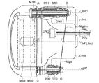
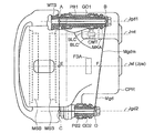
- FIG. 1 It is a schematic block diagram for demonstrating the mounting state to the vehicle of the electric braking device which concerns on embodiment of this invention. It is a whole block diagram of the braking means shown in FIG. 1, and a control means. It is a whole block diagram of a drive means in case a motor with a brush is employ
- FIG. 1 shows a state where an electric braking device according to an embodiment of the present invention is mounted on a vehicle.
- the electric braking device generates a wheel braking force by applying a braking torque to the wheel according to an operation amount of a braking operation member (for example, a brake pedal) of the driver, and decelerates the traveling vehicle.
- a storage battery (battery) BAT supplies electric power to braking means (brake actuator) BRK and an electronic control unit ECU.
- the BAT is provided (fixed) on the vehicle body BDY.
- the BAT supplies power to the drive means (drive circuit) DRV that drives the electric motor MTR via the ECU and the power line PWL.
- the electronic control unit ECU transmits a drive signal Imt to the drive circuit DRV via the signal line SGL based on the braking operation amount Bpa.
- the ECU is provided (fixed) to the vehicle body BDY.
- the drive circuit DRV is provided in the caliper CPR and includes a switching element (S1 and the like) and a noise reduction circuit. Based on the drive signal (target energization amount Imt) of the MTR transmitted from the ECU via the signal line SGL, the switching element is driven, and the rotational direction and rotational power of the MTR are controlled. Electric power for driving the MTR is supplied from the BAT to the DRV through the ECU and the power line PWL.
- the signal line SGL and the power line PWL are collectively referred to as “wiring (wire harness)”.
- power line communication in which the power line PWL is also used as a signal line (communication line) SGL may be employed.
- the SGL is integrated into the PWL (ie, the SGL is omitted), and the Imt is superimposed on the PWL and transmitted to the DRV.
- the power line communication is also referred to as power line communication (PLC) and is a communication system that performs high-speed data communication using the power supply wiring PWL.
- the suspension arm (for example, upper arm UAM, lower arm LAM) has one side attached to the vehicle body BDY of the vehicle and the other side attached to a knuckle (corresponding to a support member) NKL.
- the coil spring SPR and the shock absorber SHA are attached to a suspension arm or a knuckle NKL.
- the wheel WHL is suspended from the vehicle body BDY by the coil spring SPR and the shock absorber SHA.
- the suspension arm, SPR, NKL, and SHA are members constituting a known suspension device.
- the hub bearing unit HBU is fixed to a support member (knuckle) NKL.
- the wheel WHL is supported by a hub bearing in the hub bearing unit HBU.
- a rotating member (brake disc) KTB is fixed to the wheel WHL, and the KTB is rotated integrally with the WHL (that is, the rotating shaft of the KTB and the rotating shaft of the WHL are coaxial).
- the mounting bracket (corresponding to the mount member) MTB is fixed to the knuckle (corresponding to the support member) NKL by fastening members (for example, bolts) TK1 and TK2 (not shown).
- the caliper CPR is attached to the mount member MTB via guide members GD1, GD2 (slide pins fastened to the MTB by pin bolts PB1, PB2 (not shown)).
- the brake caliper CPR is a floating caliper and is configured to sandwich a rotating member (brake disc) KTB via two friction members (brake pads) MSB. Specifically, the slide pins GD1 and GD2 are fixed to the mount member MTB, and the pressing member PSN in the caliper CRP is slid by the electric motor MTR along the GD1 and GD2 toward the rotating member KTB.
- a vehicle including this electric braking device includes a braking operation member BP, an electronic control unit ECU, a braking means (brake actuator) BRK, and a storage battery (battery) BAT.
- control means (control algorithm) CTL for controlling the braking means BRK is programmed, and the BRK is controlled based on this.
- the storage battery BAT is a power source that supplies power to the BRK, ECU, and the like.
- the control means CTL includes a target pressing force calculation block FBT, an instruction energization amount calculation block IST, a pressing force feedback control block IPT, and an energization amount adjustment calculation block IMT.
- the control means (control program) CTL is programmed in the electronic control unit ECU.
- the target pressing force Fbt of each wheel WHL is calculated based on the braking operation amount Bpa and the preset target pressing force calculation characteristic (calculation map) CHfb.
- Fbt is a target value of the pressing force, which is a force with which the friction member (brake pad) MSB presses the rotating member (brake disc) KTB in the electric braking means BRK.
- the command energization amount Ist is calculated on the basis of preset calculation characteristics (calculation maps) CHs1 and CHs2 of the command energization amount and the target pressing force Fbt.
- Ist is a target value of the energization amount to the electric motor MTR for driving the electric motor MTR of the electric braking means BRK and achieving the target pressing force Fbt.
- the calculation map of Ist is composed of two characteristics CHs1 and CHs2 in consideration of the hysteresis of the electric braking means BRK.
- the characteristic CHs1 corresponds to the case where the pressing force is increased, and the characteristic CHs2 corresponds to the case where the pressing force is decreased. Therefore, compared with the characteristic CHs2, the characteristic CHs1 is set to output a relatively large command energization amount Ist.
- the energization amount is a state amount (variable) for controlling the output torque of the electric motor MTR. Since the electric motor MTR outputs a torque substantially proportional to the current, the current target value of the electric motor MTR can be used as the target value of the energization amount. Further, if the supply voltage to the electric motor MTR is increased, the current is increased as a result, so that the supply voltage value can be used as the target energization amount. Furthermore, since the supply voltage value can be adjusted by the duty ratio in pulse width modulation (PWM: Pulse Width Modulation), this duty ratio can be used as the energization amount.
- PWM Pulse Width Modulation
- the pressing force feedback energization amount Ipt is calculated based on the target pressing force (target value) Fbt and the actual pressing force (actual value) Fba.
- the command energization amount Ist is calculated as a value corresponding to the target pressing force Fbt, but an error (steady error) occurs between the target pressing force Fbt and the actual pressing force Fba due to the efficiency variation of the electric braking means BRK.
- the pressing force feedback energization amount Ipt is calculated based on a deviation (pressing force deviation) ⁇ Fb between the target pressing force Fbt and the actual pressing force Fba and a preset calculation characteristic (calculation map) CHp, and the above error is calculated. Decided to decrease.
- the actual pressing force Fba is acquired (detected) by a pressing force acquisition unit FBA described later.
- a target energization amount Imt that is a final target value for the electric motor MTR is calculated.
- the command energization amount Ist is adjusted by the pressing force feedback energization amount Ipt, and the target energization amount Imt is calculated. Specifically, the feedback energization amount Ipt is added to the command energization amount Ist, and this is calculated as the final target energization amount Imt.
- the brake means BRK includes a brake caliper (floating caliper) CPR, an electric motor (brush motor or brushless motor) MTR, a drive means (MTR drive circuit) DRV, a reduction gear GSK, a shaft member SFT, a screw member NJB, and a press.
- the member (brake piston) PSN, position detection means MKA, energization amount acquisition means IMA, and pressing force acquisition means FBA are configured.
- the braking means (brake actuator) BRK has two axes: an axis (rotation axis and motor axis) Jmt of the electric motor MTR and an axis (rotation axis and shaft axis) Jsf of the shaft member SFT. Configuration (ie, a biaxial configuration).
- the motor shaft Jmt is provided with position acquisition means (rotation angle sensor) MKA and small-diameter gear SKH of the reduction gear GSK.
- the shaft shaft Jsf is provided with a screw member NJB, a pressing member PSN, a pressing force acquisition means FBA, and a large-diameter gear DKH of the reduction gear GSK.
- Each component (MTR, DRV, etc.) of the braking means BRK is provided in the caliper CPR.
- the caliper CPR is slidably fixed to a mounting bracket (corresponding to a mount member) MTB.
- the mount member MTB is attached to a knuckle (corresponding to a support member) NKL.
- the MTR drive instruction value (target energization amount) Imt is sent from the electronic control unit ECU via the signal line SGL, and the drive power of the MTR is transmitted via the power line PWL.
- a connector CNC is fixed on the surface of the caliper CPR, and Imt and electric power are taken into the drive circuit DRV through the connector CNC.
- the electric motor MTR is driven by DRV to generate rotational power.
- the output of the electric motor MTR (rotational power around the motor shaft Jmt) is transmitted to the shaft member SFT via the reduction gear GSK.
- the rotational power (torque around the shaft axis Jsf) of the shaft member SFT is converted into linear power (thrust in the direction of the pressing axis Jps) by the screw member NJB, which is a motion converting member, and transmitted to the pressing member PSN.
- the pressing member (brake piston) PSN is moved forward / backward toward the rotating member (brake disc) KTB.
- the force (pressing force) Fba that the friction member (brake pad) MSB presses the rotating member KTB is adjusted.
- a frictional force is generated between the friction member MSB and the rotating member KTB, and the braking force is adjusted to the wheel WHL, for example, the traveling vehicle is decelerated.
- a conversion mechanism such as a ball ramp member, a rotary wedge member, a rack and pinion member, or the like may be employed as the conversion member for converting the rotational motion into the linear motion instead of the screw member NJB.
- the brake caliper CPR is a floating caliper, and is configured to sandwich the rotating member (brake disc) KTB via the two friction members (brake pads) MSB.
- the pressing member PSN is slid and moved forward or backward toward the rotating member KTB.
- the keyway KYM is formed so as to extend in the direction of the rotation axis (shaft axis Jsf) of the shaft member SFT.
- a motor with a brush or a brushless motor is adopted as the electric motor MTR.
- the forward rotation direction corresponds to the direction in which the friction member MSB approaches the rotation member KTB (the direction in which the pressing force increases and the braking torque increases)
- the reverse rotation direction corresponds to the friction member MSB.
- the output of the electric motor MTR is determined based on the target energization amount Imt calculated by the control means CTL.
- the electric motor MTR is driven in the forward rotation direction, and the sign of Imt is a negative sign (Imt ⁇ 0).
- the electric motor MTR is driven in the reverse direction.
- the rotational power of the electric motor MTR is determined based on the magnitude (absolute value) of the target energization amount Imt. That is, the larger the absolute value of the target energization amount Imt, the larger the output torque of the electric motor MTR, and the smaller the absolute value of the target energization amount Imt, the smaller the output torque.
- Position acquisition means (for example, rotation angle sensor) MKA detects the position (for example, rotation angle) Mka of the rotor (rotor) of the electric motor MTR.
- the position acquisition means MKA is provided inside the electric motor MTR and coaxially with the MTR (arranged on the motor shaft Jmt).
- the driving means (electric circuit for driving the electric motor MTR) DRV controls the energization amount (finally the current value) to the electric motor MTR based on the target energization amount (target value) Imt.
- the driving unit DRV includes a bridge circuit using a plurality of switching elements (power transistors such as MOS-FETs and IGBTs). These elements are driven based on the target energization amount Imt of the electric motor, and the output of the electric motor MTR is controlled. Specifically, the rotation direction and output torque of the electric motor MTR are adjusted by switching the energization / non-energization state of the switching element.
- the drive circuit DRV is provided with noise reduction circuits (stabilization circuits) LPFp and LPFt for reducing voltage fluctuation and the like.
- the noise reduction circuits LPFp and LPFt are so-called LC circuits, and are configured by a combination of an inductor (coil) IND and a capacitor (capacitor) CND.
- the energization amount acquisition means (for example, current sensor) IMA acquires (detects) an actual energization amount (for example, current that actually flows through the electric motor MTR) Ima to the electric motor MTR.
- the energization amount acquisition means IMA is provided in the electric motor drive circuit DRV.
- a connector CNC is provided on the surface of the caliper CPR. Connected between the electronic control unit ECU (arranged in the vehicle body BDY) and the drive circuit DRV (arranged in the caliper CPR) via wiring (signal line SGL and power line PWL) relayed by the connector CNC. .
- the signal line SGL transmits the target energization amount Imt from the ECU to the DRV via the connector CNC.
- the power line PWL supplies power for driving the electric motor MTR from the ECU to the DRV via the connector CNC.
- Reducer GSK reduces the rotational speed and outputs it to shaft member SFT in the power of electric motor MTR. That is, the rotational output (torque) of the MTR is increased according to the reduction ratio of the reduction gear GSK, and the rotational force (torque) of the shaft member SFT is obtained.
- the GSK is composed of a small diameter gear SKH and a large diameter gear DKH.
- a winding transmission mechanism such as a belt or a chain, or a friction transmission mechanism may be employed.
- the shaft member SFT is a rotating shaft member and transmits the rotational power transmitted from the reduction gear GSK to the screw member NJB.
- the screw member NJB is a conversion member that converts the rotational power of the shaft member SFT into linear power. That is, the screw member NJB is a rotation / linear motion conversion mechanism.
- the screw member NJB includes a nut member NUT and a bolt member BLT.
- the screw member NJB has reversibility (has reverse efficiency) and can transmit power in both directions. That is, when the braking torque is increased (when the pressing force Fba is increased), power is transmitted from the shaft member SFT to the pressing member PSN through the screw member NJB. Conversely, when the braking torque is reduced (when the pressing force Fba is reduced), power is transmitted from the pressing member PSN to the shaft member SFT via the screw member NJB (reverse efficiency is less than “0”). large).
- the screw member NJB is configured by a sliding screw (such as a trapezoidal screw) that transmits power by “sliding”.
- the nut member NUT is provided with a female screw (inner screw) MNJ.
- the bolt member BLT is provided with a male screw (outer screw) ONJ and is screwed to the MNJ of the NUT.
- the rotational power (torque) transmitted from the shaft member SFT is transmitted as linear power (thrust) of the pressing member PSN via the screw member NJB (ONJ and MNJ).
- a rolling screw such as a ball screw
- the screw member NJB may be employed for the screw member NJB.
- the nut member NUTb and the bolt member BLTb are provided with ball grooves. Power is transmitted through a ball (steel ball) BAL fitted in the ball groove.
- the reaction force (reaction) of the force (pressing force) Fba that the pressing member PSN presses the friction member MSB is acquired (detected).
- a strain generating body is formed in the FBA, and the strain is detected by a strain detection element, and Fba is acquired.
- a strain detection element a device using a change in electrical resistance (strain gauge), a device using ultrasonic waves, or the like can be used.
- the FBA is provided between the shaft member SFT and the caliper CPR.
- the FBA is fixed to the caliper CRP.
- the detected pressing force Fba is an analog signal, converted into a digital signal via an analog / digital conversion means provided in the electronic control unit ECU, and input to the ECU.
- FIG. 3 shows an example of driving means (driving circuit) DRV in the case where a motor with a brush (also simply referred to as a brush motor) is employed as the electric motor MTR.
- a motor with a brush is also called a commutator motor.
- a current flowing through an armature is rotated by a mechanical commutator (commutator) CMT and a brush BLC. It is switched according to the phase. That is, the commutator CMT and the brush BLC constitute a mechanical rotation switch, and the current to the winding circuit is alternately inverted.
- the stator (stator) side is constituted by a permanent magnet
- the rotor (rotor) side is constituted by a winding circuit (electromagnet).
- the brush BLC is in contact with the commutator CMT so that electric power is supplied to the winding circuit (rotor).
- the brush BLC is pressed against the commutator CMT by a spring (elastic body), and a current is commutated by rotating the CMT.
- Position acquisition means MKA for detecting the rotor position Mka of the electric motor MTR is provided inside the electric motor MTR.
- the MKA is disposed coaxially with the rotor and the commutator (that is, provided on the motor shaft Jmt).
- the driving means DRV is an electric circuit that drives the electric motor MTR, and the pulse width modulation block PWM that performs pulse width modulation (PWM) based on the switching elements S1 to S4 and Imt, and the PWM are determined.
- the switching control block SWT controls the energized state / non-energized state of S1 to S4 based on the duty ratio to be performed.
- the brushed motor MTR is provided with a brush BLC and a commutator CMT.
- DRV and MTR are provided on the wheel side and fixed to the CPR.
- a drive signal and power are supplied to the drive circuit DRV from the ECU provided on the vehicle body side via the connector CNC through the signal line SGL and the power line PWL.
- the switching elements S1 to S4 are elements that can turn on / off a part of the electric circuit, and for example, MOS-FETs can be used.
- a bridge circuit in the forward direction and the reverse direction of the MTR is configured by S1 to S4.
- the forward rotation direction of the MTR is a rotation direction in which the MSB is brought closer to the KTB, the braking torque is increased, and the deceleration of the traveling vehicle is increased.
- the reverse rotation direction of the MTR is to pull the MSB away from the KTB. In the rotational direction, the braking torque is reduced and the deceleration of the running vehicle is reduced.
- the switching control block SWT controls S1 and S4 to be in an energized state (ON state) and S2 and S3 to be in a non-energized state (OFF state).
- S1 and S4 are controlled to be in a non-energized state (OFF state)
- S2 and S3 are controlled to be in an energized state (ON state).
- a heat sink heat sink
- a metal plate for example, an aluminum plate having good heat conductivity can be fixed to S1 to S4.
- the duty ratio of the pulse width (ratio of ON / OFF time) is determined based on the magnitude of Imt, and the MTR value is determined based on the sign of Imt (positive sign or negative sign).
- the direction of rotation is determined.
- the rotation direction of the MTR can be set such that the forward rotation direction is a positive (plus) value and the reverse rotation direction is a negative (minus) value. Since the final output voltage is determined by the input voltage (BAT voltage) and the duty ratio, the rotation direction and output torque of the MTR are controlled by DRV.
- DRV is a filter circuit (LC circuit) for reducing noise (reducing power fluctuations) with a combination of at least one capacitor (capacitor) and at least one inductor (coil) in order to stabilize power supply.
- LC filter Also referred to as LC filter).
- the first and second capacitors CND1, CND2 and the inductor IND are combined to form a low-pass filter ( ⁇ -type filter) LPFp, and noise reduction can be performed.
- the ⁇ -type low-pass filter LPFp is a so-called Chebyshev low-pass LC filter, which is a filter composed of two capacitors CND1 and CND2 parallel to the line and one series inductor.
- an inductor is more expensive than a capacitor (capacitor), and therefore, by adopting LPFp, component costs are suppressed and good performance can be obtained.
- a T-type low-pass filter LPFt described later can be adopted as the noise reduction filter instead of LPFp (see FIG. 4 described later).
- FIG. 4 shows an example of drive means (drive circuit) DRV when the electric motor MTR is a brushless motor (three-phase brushless motor).
- the brushless motor is also referred to as a non-commutator motor (brushless direct current motor).
- current is commutated by an electronic circuit instead of the mechanical commutator CMT of the brushed motor.
- the rotor (rotor) is a permanent magnet
- the stator (stator) is a winding circuit (electromagnet).
- the rotor rotation position Mka is detected, and the switching element is switched according to Mka. As a result, the supply current is commutated.
- the rotor position Mka is detected by position acquisition means MKA provided inside the electric motor MTR.
- the driving means DRV is an electric circuit that drives the MTR, and includes switching elements Z1 to Z6, a pulse width modulation block PWM that performs pulse width modulation based on Imt, and Z1 to
- the switching control block SWT is configured to control the energization state / non-energization state of Z6.
- DRV and MTR are provided on the wheel side and are fixed to the CPR.
- a drive signal and power are supplied to the drive circuit DRV from the electronic control unit ECU provided on the vehicle body side via the connector CNC through the signal line SGL and the power line PWL.
- the position acquisition means MKA acquires the rotor position (rotation angle) Mka of the MTR.
- the switching elements Z1 to Z6 constituting the three-phase bridge circuit are controlled based on the actual position Mka.
- the switching elements Z1 to Z6 sequentially switch the direction of the coil energization amount of the U-phase, V-phase, and W-phase (that is, the excitation direction) of the bridge circuit to drive the MTR.
- the rotation direction (forward rotation or reverse rotation) of the brushless motor is determined by the relationship between the rotor and the excitation position.
- the forward direction is a rotational direction in which the MSB and KTB are brought closer to each other, the braking torque is increased, and the deceleration of the running vehicle is increased.
- This is the direction of rotation in which the brake torque is reduced and the deceleration of the running vehicle is reduced, away from the KTB.
- a heat radiating plate (for example, an aluminum plate) is fixed to the switching elements Z1 to Z6 in order to radiate heat when a high output is required.
- the duty ratio of the pulse width is determined based on the magnitude of Imt
- the rotation direction of the MTR is determined based on the sign of Imt (the sign of the value). Then, based on the target energization amount Imt, the switching elements Z1 to Z6 are controlled by signals from the SWT, whereby the rotation direction and output torque of the MTR are controlled.
- the DRV includes a filter circuit (LC circuit) for reducing noise (reducing power fluctuation) by combining at least one capacitor (capacitor) and at least one inductor (coil). And also referred to as an LC filter).
- the capacitor CND and the first and second inductors IND1 and IND2 are combined to form a low-pass filter (T-type filter) LPFt, and noise reduction can be performed.
- the T-type filter LPFt includes two series inductors IND1 and IND2 and one parallel capacitor CND.
- DRV corresponds to the case where the brush motor shown in FIG. 3 and the ⁇ -type low-pass filter LPFp are employed.
- the caliper CRP is attached to the mounting member (mounting bracket) MTB by the first and second guide members (slide pins) GD1 and GD2. Then, the caliper CPR is slid along the guide members GD1 and GD2 (sliding in the axial direction of GD1 and GD2).
- the floating caliper having this configuration is referred to as a so-called reverse type (also called a reverse pin type).
- a member having a large mass such as an electric motor MTR is provided on the wheel side.
- vibration amplification can be suppressed because a member having a large mass can be disposed between the guide members.
- the slide part by a guide member is not located in the outer periphery of a rotation member (brake disc) KTB, the radius of the rotation member KTB can be enlarged and the braking effect can be improved. For this reason, the brake actuator can be reduced in size as a whole.
- the first and second guide members (slide pins, also referred to as sleeves) GD1 and GD2 are mounted on the mount member MTB fixed to the support member NKL by the first and second pin bolts PB1 and PB2, respectively. It is attached.
- the caliper CPR can be slid in the axial directions Jgd1 and Jgd2 of the GD1 and GD2 by fitting with the first and second guide members GD1 and GD2 with a gap.
- the CPR is provided with elongated holes (the inner diameter is larger than the outer diameter of GD1 and GD2) for fitting with GD1 and GD2, through which the first and second guide members GD1 and GD2 penetrate. is doing.
- the first and second guide members GD1 and GD2 are cylindrical sleeves, and both ends of the GD1 and GD2 are pressed against the heads of the mount member MTB and the first and second pin bolts PB1 and PB2. Yes. That is, GD1 and GD2 are fastened to PB1 and PB2 to be fixed to the mount member MTB in a cantilever state. Therefore, the CPR can slide in the direction of the axis Jgd1 of GD1 and the axis Jgd2 of GD2 (parallel to Jgd1). In other words, the caliper CPR is attached to the mount member MTB in a slidable state by GD1 and GD2.
- the electronic substrate KBN of the drive circuit DRV is fixed in the caliper CPR, and the switching elements S1 to S4, the first and second capacitors CND1, CND2, the inductor IND, and other electronic components (microprocessor, resistor) Are mounted (fixed).
- the quadrangle (plane) A-B-D-C is "guide surface (guide (Rectangular) Mgd ”, and a space (square prism) perpendicular to the guide surface Mgd is referred to as a guide space Kgd.
- the point A is an intersection between the axis Jgd1 of the first guide member GD1 and the surface where one end surface of the GD1 contacts the mount member MTB.
- Point B is the intersection of Jgd1 and the surface where the other end surface of GD1 contacts the head of first pin bolt PB1.
- the point C is an intersection of the axis Jgd2 of the second guide member GD2 and the surface where one end surface of the GD2 contacts the mount member MTB
- the point D is Jgd2 and the other end surface of the GD2 is the first end surface. This is the intersection of the surface of the 2-pin bolt PB2 and the surface in contact with the head.
- the switching elements S1 to S4 constitute an H bridge circuit for driving the electric motor MTR.
- Capacitors CND1, CND2 and inductor (choke coil) IND constitute a stabilization circuit (power fluctuation reduction circuit) for supplying power to MTR.
- S1 to S4, CND1, CND2, and IND are electronic components having a relatively large mass compared to other electronic components. For this reason, at least one of these electronic components is disposed inside the caliper CPR and in the guide space Kgd formed between the first guide member GD1 and the second guide member GD2. (Fixed).
- the guide surface Mgd is a surface formed by mutually parallel guide members (slide pins) GD1 and GD2, and the caliper CPR is slid along the Mgd. From the viewpoint of road surface vibration, a place where GD1 and GD2 (that is, guide space Kgd) are difficult to amplify vibration (particularly vibration with respect to vibration perpendicular to the rotation axis (wheel axis) Jkt of rotating member KTB). It is. On the contrary, vibration amplification may become remarkable when it goes away from GD1 or GD2.
- an electronic component (such as a switching element) having a relatively large mass is arranged so as to be projected onto the guide surface Mgd in parallel projection (that is, in the guide space Kgd).
- the electronic component is placed in an advantageous place from the viewpoint of road surface vibration, and thus its reliability can be ensured.
- the caliper CPR is fitted with the first and second guide members GD1 and GD2 and slides in the KTB axis Jkt direction, so that the axis GD1 and the axis Jgd2 of GD2 are required to be parallel.
- an error is included in the degree of parallelism between Jgd1 and Jgd2 due to the relationship between CPR processing accuracy and mounting accuracy.
- the plane is basically determined by three points, a master-slave relationship can be provided in the relationship between GD1 and GD2. For example, assuming that GD1 is “main” and GD2 is “sub”, the main guide member GD1 is set longer in the axial direction than the sub guide member GD2.
- the gap between GD1 and CPR (the gap between the outer diameter and the hole diameter) can be set narrower than the gap between GD2 and CPR.
- GD1 can be a cantilever structure with respect to MTB
- GD2 can be a cantilever structure with respect to MTB.
- the CRP is basically slid along the main guide member GD1. Then, the movement of the slide is assisted by the sub guide member GD2 so that the guide surface Mgd is formed. In this case, in MGD, the closer to the main guide member GD1, the more favorable the condition for vibration.
- the at least one electronic component is disposed in proximity to the main guide member GD1.
- the corresponding member is arranged on the side closer to the axis Jgd1 of the main guide member GD1 with respect to the axis Jsf of the shaft member (same as the axis Jps of the pressing member PSN).
- a surface (rectangle A-B-F-E) that is a part of the guide surface Mgd (divided into two) and is close to GD1 (including GD1) is a main guide surface (main guide rectangle) Mgdm. Is done.
- a space (square prism) perpendicular to the main guide surface Mgdm is defined as a main guide space Kgdm.
- the switching elements S1 to S4 that form a bridge circuit which are electronic components having a relatively large mass, the first and second capacitors CND1, CND2, and the inductor (choke coil) IND that form a fluctuation reduction circuit of the supplied power At least one of them can be arranged inside the caliper CPR and in the main guide space Kgdm.
- at least one of S1 to S4, CND1, CND2, and IND fixed inside the CPR when projected from a direction perpendicular to the guide surface Mgd (guide quadrangle ABCD-C).
- One electronic component is projected onto the main guide surface Mgdm (main guide rectangle A-B-F-E).
- the guide surface Mgd (square A-B-D-C) is divided into two parts (rectangle A-B-F-E) by the surface formed by the shaft axis Jkt and the shaft axis Jsf (pressing axis Jps).
- Square E-F-D-C which is divided (divided) into a main guide surface Mgdm (a main guide quadrangle A-B-F-, which is the surface of the two parts including the main guide member GD1).
- E) is a projection plane of the corresponding electronic component (S1 or the like).
- the resistor (resistor) R, the small capacitor C, or the microprocessor MPC having a relatively small mass can be disposed in the caliper CPR by deviating from the above-described vibrationally advantageous spaces (Kgd, Kgdm).
- vibrationally advantageous spaces Kgd, Kgdm.
- prioritization in layout is performed based on the mass of electronic components, electronic components with large mass are preferentially arranged in a place advantageous for vibration, and electronic components with small mass are It is placed in a vacant place. For this reason, it is possible to suppress the vibration from being amplified with respect to the vibration caused by the road surface unevenness during traveling of the vehicle, and to improve the reliability of the braking means BRK.
- the switching elements Z1 to Z6 constitute a three-phase bridge circuit for driving the MTR, and the capacitors CND,
- the first and second inductors (choke coils) IND1 and IND2 constitute a stabilization circuit (power fluctuation reduction circuit) for supplying power to the MTR, but these are electronic components having a relatively large mass. . Therefore, at least one of these electronic components can be disposed inside the caliper CPR and in the guide space Kgd.
- At least one of IND1 and IND2 may be disposed in the caliper CPR at a location overlapping the guide space Kgdm.
- the main guide space Kgdm is the guide space Kgd on the side including the main guide member GD1 among the two guide spaces separated by the formation surface of Jkt and Jsf (Jps).
- the condition that GD1 is the main guide member is that “GD1 is longer than GD2”, “the gap between GD1 and CPR is narrower than the gap between GD2 and CPR”, and “GD1 with respect to MTB. That is, at least one of the three conditions that “is a double-supported structure and GD2 is a cantilever structure” is satisfied.
- collet-type floating calipers that have a structure in which a guide member (slide pin) is fixed to the caliper and slides in a mounting member (mounting bracket).
- a guide member (slide pin) is fixed to the caliper and slides in a mounting member (mounting bracket).
- the guide member is provided on the outer peripheral portion of the rotating member (brake disc)
- the guide space Kgd overlaps with the rotating member MTB.
- a reverse floating caliper in which the guide members GD1 and GD2 are located on the side surface of the rotating member KTB (that is, the guide space Kgd is formed on the side surface of the KTB) can be employed.
- the connector CNC can be disposed (fixed) on the above-described space (guide spaces Kgd, Kgdm) that is advantageous in terms of vibration and on the surface of the caliper CPR.
- the connector is a connector (relay member) that can be electrically connected to connect wiring in an electronic circuit, communication, or the like.
- the wiring is connected by solder bonding or crimping, the wiring needs to be cut to make the reconnection difficult.
- the connector is configured by fixing an electric signal and a metal terminal (contact pin) for transmitting electric power to a resin insulator (insulator) surrounding them.
- a convex male connector and a concave female connector are used as a pair.
- the drive signal and power of the electric motor are transmitted to the drive means DRV of the electric motor by the power supply line PWL, the signal line SGL, and the connector CNC that are close to each other.
- the circuit board of the electronic control unit ECU fixed to the vehicle body and the circuit board KBN of the DRV fixed to the CPR are electrically and electronically connected via the connector CNC.
- the electric motor drive signal Imt is generated inside the ECU and transmitted to the DRV via a signal line (for example, a communication bus line) SGL.
- the electric power for driving the electric motor is supplied from the storage battery BAT to the electronic control unit ECU, and is supplied from the ECU to the drive circuit DRV through the power line PWL.
- the fitting portion (the portion where the female connector and the male connector are fitted) and the joint portion between the wiring (power line PWL, signal line SGL) and the contact pin are easily affected by vibration.
- the connector CNC can be arranged on the surface of the caliper CPR and in the guide space Kgd.
- the guide surface Mgd guide quadrangle ABCD-C formed by the end points of the first and second guide members GD1, GD2
- the connector CNC is projected onto the guide surface Mgd.
- the connector CNC is the surface of the caliper CPR and overlaps the main guide space Kgdm. Can be placed in place.
- the main guide space Kgdm is the guide space Kgd on the side including the main guide member GD1 among the two guide spaces separated by the formation surface of Jkt and Jsf (Jps).
- the condition that GD1 is the main guide member is that “GD1 is longer than GD2”, “the gap between GD1 and CPR is narrower than the gap between GD2 and CPR”, and “GD1 with respect to MTB. That is, at least one of the three conditions that “is a double-supported structure and GD2 is a cantilever structure” is satisfied.
- the connector CNC In the connector CNC, energization in the wiring is performed by contact of the contact pins (fitting of the male pin and the female pin), and this contact may be loosened by vibration. Furthermore, the power line PWL that supplies power requires a cross-sectional area that is necessary for flowing current, and thus requires a certain amount of wiring. For this reason, bending fatigue caused by bending due to vibration must be taken into consideration. As described above, since the connector CNC is fixed on the caliper CPR surface at a vibrationally advantageous place (for example, in Kgd), contact of the contact pin or wiring (particularly, thickness is required). The influence of vibration in the bending of the power line PWL) can be suppressed.
- power line communication in which the power line PWL is used as the signal line SGL can be adopted.
- an electric motor drive signal Imt is transmitted superimposed on the power line PWL.
- the signal line SGL is omitted, and the wiring is only the power line PWL.
- the wiring (PWL) is drawn into the DRV in the CPR through the CNC on the CPR surface.
- FIG. 7 shows a caliper CPR, a mount member MTB, and a support member NKL that are attached by first and second guide members (slide pins) GD1 and GD2 and first and second fastening members (for example, bolts) TK1 and TK2.
- first and second guide members silica pins
- first and second fastening members for example, bolts
- TK1 and TK2 first and second fastening members
- the point K is the shaft (first fastening shaft) Jtk1 of the first fastening member (first fastening bolt) TK1
- the point L is the shaft (second fastening shaft) Jtk2 of the second fastening member (second fastening bolt) TK2. It corresponds to.
- a straight line HG connecting Jgd1 (point H) and Jgd2 (point G) corresponds to the guide surface Mgd.
- the caliper CPR is fixed to the mount member MTB so as to be slidable.
- the farther the caliper CPR is from the MTB in the wheel axis Jkt direction the greater the influence of vibration when the wheel is vibrated.
- the single-axis configuration in which the electric motor, the speed reducer, the rotation / linear motion conversion member, and the brake piston are arranged in a row is not adopted because it becomes longer in the axial direction.
- a two-axis configuration is adopted in which the electric motor MTR and the pressing member PSN are composed of two different shafts (motor shaft Jmt and pressing shaft Jps).
- the shaft can be divided into two axes Jmt and Jsf (Jps) at the reduction gear GSK. Since the braking means BRK is composed of two different shafts (Jmt, Jsf) and the speed reducer GSK is provided between the shafts (between Jmt and Jsf), the inter-shaft distance djk (distance between Jmt and Jsf) ) Can be set longer. As a result, the reduction ratio of the reduction gear GSK is set large, and a small electric motor (high speed / low torque type) can be employed.
- the mount member MTB is fixed to the support member (knuckle) NKL with a first fastening member (first fastening bolt) TK1 and a second fastening member (second fastening bolt) TK2.
- first fastening bolt first fastening bolt
- second fastening bolt second fastening bolt
- a surface (referred to as a fastening surface Mtk) formed perpendicular to each axis is an advantageous place for road surface vibration.
- the inside of the fastening surface Mtk is a region (space) in which vibration is not easily amplified. Note that Jkt, Jgd1, Jgd2, Jtk1, and Jtk2 are parallel to each other.
- the axis Jps of the pressing member PSN (that is, the axis Jsf of the shaft member SFT) is arranged at the center of the plane (that is, Mgd) that connects the axis Jgd1 of GD1 and the axis Jgd2 of GD2. Since the PSN axis Jps (that is, the SFT axis Jsf) is arranged at the center of Jgd1 and Jgd2, the MSB can be uniformly pressed against the KTB. Then, the MTR is fixed to the CPR so that the rotation shaft (motor shaft) Jmt of the electric motor MTR is orthogonal to the fastening surface Mtk.
- the brush BLC and the commutator CMT constituting the electric motor MTR are projected onto the fastening surface Mtk when viewed from the Jkt direction.
- a position acquisition means (rotation angle detection means) MKA is arranged around the motor shaft Jmt. Therefore, when the position acquisition means MKA is seen from the Jkt direction, it is projected on the fastening surface Mtk.
- the brush BLC of the electric motor MTR is slid and rotated while being pressed against a commutator (a rotary switch that periodically changes the direction of current) CMT by a spring (see FIG. 3).
- a commutator a rotary switch that periodically changes the direction of current
- the spring force is increased so that the brush BLC is not separated from the commutator CMT by vibration (a spring having a large spring constant is employed)
- the sliding resistance is increased and the torque loss can be increased.
- the positions of BLC and CMT are places where vibration amplification is difficult. Since road surface vibration while the vehicle is running may be concerned about reliability degradation and noise effects, the MKA can also be installed in a place where vibration amplification is difficult.
- the axes of the fastening members TK2) Jtk2 are parallel to each other.
- Jsf and the pressing axis Jps are coaxial.
- Jgd1, Jgd2, and Jsf (Jps) are on the same plane (on the guide surface Mgd), and the distance between Jgd1 and Jsf (Jps) and the distance between Jgd2 and Jsf (Jps) are made equal. That is, Jsf (Jps) is at the center of Jgd1 and Jgd2.
- the rotating shaft (motor shaft) Jmt of the electric motor is orthogonal to the fastening surface Mtk (included in a space perpendicular to the square GHLK) and is closer to Jkt than Jsf (Jps) (that is, the guide). (On the Jkt side with respect to the surface Mgd). Further, Jmt is arranged away from Jgd1 (or Jgd2) by a distance corresponding to at least the radius of MTR.
- the distance between Jsf (Jps) and Jmt (interaxial distance djk) can be set as long as possible so as not to interfere with the pressing member PSN and the first guide member GD1.
- the reduction ratio of the reduction gear GSK is set large, and the MTR can be downsized.
- the circuit board KBN1 of the driving means DRV When viewed in the first guide axis Jgd1 direction (Jkt direction or the like), the circuit board KBN1 of the driving means DRV is projected into the fastening surface Mtk.
- electronic components with relatively large mass switching elements S1 to S4, Z1 to Z6, capacitors CND in the voltage fluctuation reduction circuit mounted (fixed) on the substrate KBN1 of the drive circuit DRV. , CND1, CND2, and inductors IND, IND1, IND2, etc.
- the connector CNC is projected into Mtk.
- the rotation axis Jmt of the MTR is accommodated in a space projected on the fastening surface Mtk (referred to as a square pillar, the fastening space Ktk). Placed in.
- the entire brake actuator is shortened in the axial direction, and substantially the entire MTR (particularly, the motor brush BLC and the motor commutator CMT) and the rotation angle acquisition means MKA are positioned inside the fastening space Ktk. .
- the vibration influence from the road surface with respect to these components can be suppressed.
- the electronic component such as IND
- the connector CNC are also housed in the fastening space Ktk, the influence of vibration can be reduced and the reliability can be improved.
- the fastening surface Mtk is divided (divided into two parts) by a plane formed by Jsf (that is, Jps) and Jkt (a plane including a straight line Sgh intersecting Jsf (Jps) and Jkt on Mtk).
- the main fastening surface Mtkm is a portion on one side of the divided Mtk and is a quadrangle defined by a plane (straight line Sgh) including the main guide shaft Jgd1 (the shaft of the main guide member GD1).
- G-M-N-K A set of straight lines (quadrangular prisms) perpendicular to the plane (main fastening surface) Mtkm is referred to as a main fastening space Ktkm.
- the motor shaft Jmt is disposed within the main fastening surface Ktkm
- the motor brush BLC, the motor commutator CMT, and the position acquisition means MKA can be disposed together within Ktkm.
- at least one of switching elements (for example, S1 to S4) for driving the MTR, an inductor (coil) IND for suppressing voltage fluctuation, a capacitor (capacitor) CND, and the like is provided on the main fastening surface Ktkm.
- a connector for wiring for supplying a drive signal and electric power from the electronic control unit ECU to the drive circuit DRV can be arranged in the main fastening surface Ktkm.
- the Jmt fastening space Ktk (or the main fastening space Ktkm) Inward placement may be prioritized.
- the substrate KBN2 of the drive circuit DRV can be disposed away from the fastening space Ktk and disposed on the opposite side of the wheel shaft Jkt with respect to the guide surface Mgd.
- the electronic substrate KBN2 can be disposed on the side closer to the main guide member GD1 with respect to the formation surface (indicated by the line segment Sgh) of Jkt and Jps (Jsf). KBN2 can be placed at a location between Jps (Jsf) and Jgd1.
- electronic components mounted on KBN2 capacitors CND, CND1, CND2 of a relatively large mass noise reduction circuit, inductors IND, IND1, IND2, and at least one of switching elements S1 to S4, Z1 to Z6
- the connector CNC is disposed inside the fastening space Ktk on the opposite side to the main fastening space Ktkm.
- the motor shaft Jmt is disposed inside the fastening space Ktk on the side opposite to the main fastening space Ktkm (Ktk on the side including GD2 separated by the formation surface of Jkt and Jps), and the capacitor CND of the noise reduction circuit, At least one of CND1, CND2, inductors IND, IND1, IND2, switching elements S1 to S4, Z1 to Z6, and connector CNC may be disposed in the main fastening space Ktkm.
- the arrangement of each component depends on the priority for their vibration effects.
- Some sensors include elements that are vulnerable to vibrations, and noise effects due to vibrations may also be a concern. For this reason, when viewed in the direction perpendicular to the guide surface Mgd, FBA and / or MKA are projected onto the guide surface Mgd (particularly, the guide surface Mgdm on the main guide member GD1 side when the guide member has a master-slave). Is done. That is, the positions of the FBA and MKA can be set inside the guide space Kgd (or the main guide space Kgdm). Since these are disposed in a place (space) that is advantageous in terms of vibration, the concern about road surface vibration during vehicle travel can be eliminated.
- the motor brush BLC and the motor commutator CMT are disposed in the guide space Kgd (or the main guide space Kgdm), and their positions are , Projected onto the guide surface Mgd (or the main guide surface Mgdm).
- the motor brush BLC slides while being pressed against the commutator CMT by a spring (elastic body).
- a spring elastic body
- the braking means BRK has a so-called two-axis configuration in which the rotation axis Jmt of the electric motor MTR that is a power source and the PSN axis (pressing axis Jps) that presses the MSB are configured as separate axes.
- the rotational power of the MTR is decelerated, transmitted to the SFT, and further rotated / linearly converted by the NJB, and the PSN presses the MSB against the KTB. Therefore, the PSN axis Jps and the SFT rotation axis Jsf are the same axis.
- the electric motor MTR is fixed to the floating caliper CPR.
- the CPR includes a drive circuit DRV for driving the MTR (fixed inside).
- a bridge circuit is formed by a switching element in order to drive the MTR.
- a low-pass filter circuit is formed by an inductor and a capacitor in order to stabilize (variation reduction) the power supplied to the MTR.
- the power to the drive circuit DRV and the drive signal for the electric motor MTR are supplied from the electronic control unit ECU fixed to the vehicle body through the connector CNC.
- a position acquisition means for example, a rotation angle sensor
- MKA is provided around the rotation axis (Jmt) of the electric motor MTR.
- the actual position (rotation angle) Mka of the electric motor MTR is detected by the MKA.
- the switching element is synchronized by Mka, and the MTR is driven.
- the MTR is a motor with a brush
- a mechanical commutator CMT and a brush BLC are provided.
- a pressing force acquisition means for example, a thrust sensor
- FBA for detecting a pressing force Fba that is a force by which the friction member MSB presses the rotating member KTB is provided.
- FIG. 9 shows a guide surface Mgd (guide quadrangle ABCD-C) formed by the first and second guide members GD1 and GD2, and a guide space Kgd perpendicular to the plane.
- each of the four corners of the quadrangle A-B-D-C (guide surface Mgd) is respectively the both ends (point A, point B) of the first guide member GD1 and the both ends (points) of the second guide member GD2.
- C, point D point D
- the point A is an intersection of the surface where one end surface of the GD1 is in contact with the mount member MTB and the axis (first guide axis) Jgd1 of the first guide member GD1
- the point B is the point of the GD1.
- the other end surface is an intersection of the surface that contacts the head of the first pin bolt PB1 and the first guide shaft Jgd1.
- point C is the intersection of the surface of one end surface of GD2 that contacts the mount member MTB and the axis (second guide axis) Jgd2 of the second guide member GD2, and point D is the other point of GD2.
- the end surface of the second pin bolt PB2 is a point of contact with the head and the second guide shaft Jgd2. Since the CPR is attached to the MTB by the GD1 and the GD2, the position closer to the Mgd is less susceptible to road surface uneven vibration during vehicle travel.
- the road surface vibration is input in a random direction (arbitrary direction). In this case, the vibration effect in the direction indicated by the “ZA arrow” (direction perpendicular to the wheel axis Jkt) is particularly problematic. .
- Kgd A place where the influence of vibration from the road surface during traveling of the vehicle (particularly, the ZA direction perpendicular to Jkt) can be suppressed is the guide space Kgd.
- the components of BRK that require vibration resistance are provided inside Kgd. Since Kgd is an aggregate of straight lines perpendicular to Mgd, these components are projected onto Mgd when viewed from a direction perpendicular to Mgd.
- the projection is to irradiate an object with parallel rays (projection lines) and project the shadow of the object on a plane. Therefore, when parallel projection (projection where the viewpoint exists at infinity) is performed on the components provided in Kgd, the guide surface Mgd is a projection surface (a vertical surface of the projection line).
- arranged in the guide space Kgd (or Kgdm) means “guide surface Mgd when viewed from the direction (ZV1 or ZV2) perpendicular to the guide surface Mgd (or Mgdm)”. (Or be positioned inside (or Mgdm)) and “the guide surface Mgd (or Mgdm) becomes the projection surface”.
- Components that require vibration resistance are relatively heavy in electronic components mounted (fixed) on a DRV circuit board KBN that is fixed in the CPR. Specifically, the switching elements of the drive bridge circuit of the MTR (particularly heavy when the heat sink is provided), the inductor and the capacitor of the power supply noise reduction circuit. Even with the same acceleration, if the mass is large, the inertial force is large. Further, since the electronic component is fixed to the circuit board at the conductor (conductive wire) portion, the inertial force is concentrated on this portion. Therefore, vibration resistance can be improved by arranging at least one of these electronic components fixed in the CPR inside the Kgd.
- a component having a high demand for vibration resistance is a connector CNC fixed to the surface of the CPR.
- Electric power is transmitted from the electronic control unit ECU to the drive circuit DRV of the electric motor MTR through the power line PWL, and a drive signal is transmitted through the signal line SGL (for example, a communication bus).
- PWL and SGL are relayed by the connector CNC.
- PWL and SGL are divided and joined by contact pins (fitting of concavo-convex pins) inside the CNC. When excessive vibration is applied, the contact pin may loosen.
- a predetermined cross-sectional area is required, but flexibility with respect to vibration and fatigue strength are required.
- At least one of the position acquisition means MKA and the pressing force acquisition means FBA can be arranged in the guide space Kgd.
- the brush BLC portion and the commutator CMT portion of the electric motor MTR can be disposed in the guide space Kgd. This is because the BLC is pressed against the CMT by a spring (spring), and energization to the MTR is ensured.
- Kgdm the guide space on the side close to the main member GD1 (main guide space)
- the “master-slave relationship” of the guide member is “one side is longer than the other”, “one gap is narrower than the other in the fitting hole with the CPR”, and “one side is supported by both ends” "The other is cantilever support” means that at least one condition is satisfied.
- Kgd is divided into two parts by a plane constituted by Jkt and Jsf.
- the one including GD1 (the above-mentioned one side guide member) is the main guide space Kgdm. . That is, in Mgd, a space constituted by a set of straight lines perpendicular to the main guide surface Mgdm (main guide quadrangle A-B-F-E) that is separated by Jsf and includes GD1 is Kgdm. .
- the CRP is slid along the main guide member GD1, and the movement of the slide is assisted by the sub guide member GD2.
- the closer to the main guide member GD1 the more advantageous in terms of vibration. Therefore, the components requiring vibration resistance are arranged in Kgdm, and their projection surfaces are Mgdm.
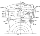
- FIG. 10 shows a fastening surface Mtk (fastening square GHLK) formed by the fastening members TK1 and TK2 and the guide members GD1 and GD2, and a fastening space Ktk perpendicular to the plane.
- the fastening surface Mtk is perpendicular to each axis by the axis Jgd1 of the first guide member GD1, the axis Jgd2 of the second guide member GD2, the axis Jtk1 of the first fastening member TK1, and the axis Jtk2 of the second fastening member TK2.
- Each point of the four corners of the quadrangle G-HL-K is a first guide member when assuming a plane (for example, the surface of the mount member MTB) perpendicular to the rotation axis (wheel axis) Jkt of the rotation member KTB.
- the point of intersection of the GD1 axis (first guide axis) Jgd1 is the point G
- the point of intersection of the second guide member GD2 (second guide axis) Jgd2 is the point H
- the intersection with the axis (first fastening axis) Jtk1 corresponds to the point K
- the intersection with the axis (second fastening axis) Jtk2 of the second fastening member (second fastening bolt) TK2 corresponds to the point L.
- the rotation axis Jkt of the KTB, the axes Jgd1 and Jgd2 of the guide member, the axes Jtk1 and Jtk2 of the fastening member, the rotation axis Jmt of the electric motor, and the rotation axis Jsf of the shaft member are parallel to each other.
- the axis (pressing direction) Jps of the pressing member is the same as Jsf. Therefore, these axes (such as Jkt) and the fastening surface Mtk are perpendicular.
- a straight line HG connecting Jgd1 (point H) and Jgd2 (point G) corresponds to the guide surface Mgd.
- the mount member MTB is attached to the support member (knuckle) NKL by the fastening members TK1 and TK2, and the caliper CPR is attached to the mount member MTB by the guide members GD1 and GD2.
- the closer to the fastening surface Mtk the less likely to be affected by road surface vibration.
- road surface vibration during vehicle travel is input in a random direction (arbitrary direction).
- the vibration effect in the direction indicated by the “ZB arrow” (direction of the wheel axis Jkt) is particularly problematic. Is done.
- Jps is placed in the middle of Jgd1 and Jgd2 so that the MSB can be pressed in the middle by the PSN. Since Jps and Jsf are on the same axis, Jsf is provided at the center of Jgd1 and Jgd2. And it arrange
- a component of the braking means BRK that requires vibration resistance is provided inside the fastening space Ktk. Since the fastening space Ktk is a collection of straight lines perpendicular to the fastening surface Mtk, these components are projected onto the fastening surface Mtk when viewed from the direction perpendicular to the fastening surface Mtk (for example, the direction of Jgd1). Is done. As described above, the projection is to irradiate an object with parallel rays (projection lines) and project the shadow of the object on a plane.
- the fastening surface Mtk is set as a projection surface (a vertical surface of the projection line). That is, “arranged in the fastening space Ktk (or Ktkm)” means “fastening surface Mtk (or Mtkm) when viewed from the direction (ZH1 or ZH2) of the axis Jgd1 of the first guide member GD1. ) ”And“ the fastening surface Mtk (or Mtkm) is the projection surface ”.
- the components of the braking means BRK can be arranged inside the fastening space Ktk.
- electronic components fixed in the caliper CPR at least one of relatively heavy components (a switching element of an MTR drive bridge circuit, an inductor of a power supply noise reduction circuit, and a capacitor) is connected to the fastening space Ktk.
- a connector CNC fixed on the caliper CPR can be arranged inside the fastening space Ktk.
- the detection means such as a sensor, at least one of the position acquisition means MKA and the pressing force acquisition means FBA may be disposed in the fastening space Ktk.
- the BLC portion and the CMT portion of the MTR can be arranged in the Ktk.
- the fastening space (main fastening space) Ktkm near the main member GD1 Inside, at least one of the above-mentioned components is arranged. Similarly to Kgd, Ktk is also divided into two by a plane constituted by Jkt and Jsf (Jps). Of these spaces, the one including the main guide member GD1 is the main fastening space Ktkm. Is done.
- the fastening surface Mtk is separated by the formation surface of Jsf (Jps) and Jkt, and is perpendicular to the main fastening surface Mtkm (main fastening quadrangle G-M-N-K) including the main guide member GD1.
- a space constituted by a set of straight lines is the main fastening space Ktkm.
- the above-mentioned components requiring vibration resistance are arranged in the main fastening space Ktkm, and these projection surfaces can be the main fastening surface Mtkm.
Landscapes
- Engineering & Computer Science (AREA)
- General Engineering & Computer Science (AREA)
- Mechanical Engineering (AREA)
- Braking Arrangements (AREA)
Abstract
L'invention concerne un dispositif de freinage électrique pour un véhicule, des premier et second éléments de guidage (GD1, GD2) étant fixés parallèlement l'un à l'autre sur un élément de montage (MTB) fixé à un élément de support supportant une roue. Un étrier (CPR) est supporté par les premier et second éléments de guidage (GD1, GD2) de sorte à être relativement mobile dans la direction de ligne d'axe. Un moteur électrique (MTR) est fixé à l'étrier (CPR). Des éléments de commutation (S1-S4) permettant de commander le moteur électrique (MTR), un indicateur (IND), et des condensateurs (CND1, CND2) sont logés à l'intérieur de l'étrier (CPR), et sont positionnés à l'intérieur d'un quadrilatère de guidage (Mgd, quadrilatère A-B-C-D), lorsqu'observés à partir de la direction verticale par rapport au plan horizontal du quadrilatère de guidage (Mgd), qui comporte « en tant que ses quatre côtés, les deux points d'extrémité (A, B) du premier élément de guidage (GD1) et les deux points d'extrémité (C, D) du second élément de guidage (GD2) ». Par conséquent, un dispositif de freinage électrique, qui comprend un moteur électrique côté roue et son circuit d'entraînement, peut être fourni, lequel dispositif présente une fiabilité améliorée de composants électroniques, tels qu'un circuit d'entraînement, en ce qui concerne les vibrations lors du déplacement du véhicule.
Applications Claiming Priority (4)
| Application Number | Priority Date | Filing Date | Title |
|---|---|---|---|
| JP2013-012489 | 2013-01-25 | ||
| JP2013-012492 | 2013-01-25 | ||
| JP2013012489A JP5880875B2 (ja) | 2013-01-25 | 2013-01-25 | 車両の電動制動装置 |
| JP2013012492A JP5907350B2 (ja) | 2013-01-25 | 2013-01-25 | 車両の電動制動装置 |
Publications (1)
| Publication Number | Publication Date |
|---|---|
| WO2014115873A1 true WO2014115873A1 (fr) | 2014-07-31 |
Family
ID=51227661
Family Applications (1)
| Application Number | Title | Priority Date | Filing Date |
|---|---|---|---|
| PCT/JP2014/051685 Ceased WO2014115873A1 (fr) | 2013-01-25 | 2014-01-27 | Dispositif de freinage électrique de véhicule |
Country Status (1)
| Country | Link |
|---|---|
| WO (1) | WO2014115873A1 (fr) |
Cited By (1)
| Publication number | Priority date | Publication date | Assignee | Title |
|---|---|---|---|---|
| WO2026092082A1 (fr) * | 2024-10-29 | 2026-05-07 | 华为数字能源技术有限公司 | Frein electromécanique et véhicule |
Citations (4)
| Publication number | Priority date | Publication date | Assignee | Title |
|---|---|---|---|---|
| JPH0135218B2 (fr) * | 1981-03-25 | 1989-07-24 | Sumitomo Electric Industries | |
| JP2000283196A (ja) * | 1999-03-31 | 2000-10-13 | Tokico Ltd | 電動式ブレーキ装置 |
| JP2008095909A (ja) * | 2006-10-16 | 2008-04-24 | Hitachi Ltd | 電動ブレーキ装置 |
| JP2008238987A (ja) * | 2007-03-28 | 2008-10-09 | Hitachi Ltd | 電動ブレーキ装置 |
-
2014
- 2014-01-27 WO PCT/JP2014/051685 patent/WO2014115873A1/fr not_active Ceased
Patent Citations (4)
| Publication number | Priority date | Publication date | Assignee | Title |
|---|---|---|---|---|
| JPH0135218B2 (fr) * | 1981-03-25 | 1989-07-24 | Sumitomo Electric Industries | |
| JP2000283196A (ja) * | 1999-03-31 | 2000-10-13 | Tokico Ltd | 電動式ブレーキ装置 |
| JP2008095909A (ja) * | 2006-10-16 | 2008-04-24 | Hitachi Ltd | 電動ブレーキ装置 |
| JP2008238987A (ja) * | 2007-03-28 | 2008-10-09 | Hitachi Ltd | 電動ブレーキ装置 |
Cited By (1)
| Publication number | Priority date | Publication date | Assignee | Title |
|---|---|---|---|---|
| WO2026092082A1 (fr) * | 2024-10-29 | 2026-05-07 | 华为数字能源技术有限公司 | Frein electromécanique et véhicule |
Similar Documents
| Publication | Publication Date | Title |
|---|---|---|
| JP5970385B2 (ja) | 車両の電動制動装置 | |
| JP6439709B2 (ja) | 車両の電動制動装置 | |
| JP6443354B2 (ja) | 車両の電動制動装置 | |
| US7516823B2 (en) | Electric braking apparatus | |
| CN111845921A (zh) | 电动驱动装置 | |
| WO2021117651A1 (fr) | Dispositif d'entraînement électrique et dispositif de direction électrique | |
| JP5017311B2 (ja) | 電動式ブレーキ制御装置 | |
| JP5284217B2 (ja) | 車両用電子回路装置 | |
| JP5880875B2 (ja) | 車両の電動制動装置 | |
| JP5907350B2 (ja) | 車両の電動制動装置 | |
| JP6198549B2 (ja) | 車両の電動制動装置 | |
| CN111095782A (zh) | 永磁体型同步电动机及电动助力转向装置 | |
| JP6793205B2 (ja) | 車両のためのアクチュエータ装置、ブレーキシステム | |
| JP6838254B2 (ja) | 電動駆動装置 | |
| JP2017128283A (ja) | 車両の電動制動装置 | |
| JP6800261B2 (ja) | 電動駆動装置 | |
| JP3788106B2 (ja) | 電動式ステアリング装置 | |
| WO2023234028A1 (fr) | Dispositif de frein pour véhicule | |
| JP6252077B2 (ja) | 車両の電動制動装置 | |
| US20260117832A1 (en) | Vehicle brake system and brake assembly | |
| JP6090061B2 (ja) | 車両の電動制動装置 | |
| JP2014184743A (ja) | ブレーキ制御装置 | |
| JP2006273184A (ja) | 電動制動装置 | |
| JP2015040027A (ja) | 車両の電動制動装置 |
Legal Events
| Date | Code | Title | Description |
|---|---|---|---|
| 121 | Ep: the epo has been informed by wipo that ep was designated in this application |
Ref document number: 14743444 Country of ref document: EP Kind code of ref document: A1 |
|
| NENP | Non-entry into the national phase |
Ref country code: DE |
|
| 122 | Ep: pct application non-entry in european phase |
Ref document number: 14743444 Country of ref document: EP Kind code of ref document: A1 |