WO2014119050A1 - 粒子線治療システム - Google Patents
粒子線治療システム Download PDFInfo
- Publication number
- WO2014119050A1 WO2014119050A1 PCT/JP2013/077640 JP2013077640W WO2014119050A1 WO 2014119050 A1 WO2014119050 A1 WO 2014119050A1 JP 2013077640 W JP2013077640 W JP 2013077640W WO 2014119050 A1 WO2014119050 A1 WO 2014119050A1
- Authority
- WO
- WIPO (PCT)
- Prior art keywords
- irradiation
- collimator
- compensation device
- therapy system
- particle beam
- Prior art date
- Legal status (The legal status is an assumption and is not a legal conclusion. Google has not performed a legal analysis and makes no representation as to the accuracy of the status listed.)
- Ceased
Links
Images






Classifications
-
- A—HUMAN NECESSITIES
- A61—MEDICAL OR VETERINARY SCIENCE; HYGIENE
- A61N—ELECTROTHERAPY; MAGNETOTHERAPY; RADIATION THERAPY; ULTRASOUND THERAPY
- A61N5/00—Radiation therapy
- A61N5/10—X-ray therapy; Gamma-ray therapy; Particle-irradiation therapy
- A61N5/1042—X-ray therapy; Gamma-ray therapy; Particle-irradiation therapy with spatial modulation of the radiation beam within the treatment head
- A61N5/1043—Scanning the radiation beam, e.g. spot scanning or raster scanning
-
- A—HUMAN NECESSITIES
- A61—MEDICAL OR VETERINARY SCIENCE; HYGIENE
- A61N—ELECTROTHERAPY; MAGNETOTHERAPY; RADIATION THERAPY; ULTRASOUND THERAPY
- A61N5/00—Radiation therapy
- A61N5/10—X-ray therapy; Gamma-ray therapy; Particle-irradiation therapy
-
- A—HUMAN NECESSITIES
- A61—MEDICAL OR VETERINARY SCIENCE; HYGIENE
- A61N—ELECTROTHERAPY; MAGNETOTHERAPY; RADIATION THERAPY; ULTRASOUND THERAPY
- A61N5/00—Radiation therapy
- A61N5/10—X-ray therapy; Gamma-ray therapy; Particle-irradiation therapy
- A61N5/103—Treatment planning systems
- A61N5/1031—Treatment planning systems using a specific method of dose optimization
-
- A—HUMAN NECESSITIES
- A61—MEDICAL OR VETERINARY SCIENCE; HYGIENE
- A61N—ELECTROTHERAPY; MAGNETOTHERAPY; RADIATION THERAPY; ULTRASOUND THERAPY
- A61N5/00—Radiation therapy
- A61N5/10—X-ray therapy; Gamma-ray therapy; Particle-irradiation therapy
- A61N5/1042—X-ray therapy; Gamma-ray therapy; Particle-irradiation therapy with spatial modulation of the radiation beam within the treatment head
- A61N5/1045—X-ray therapy; Gamma-ray therapy; Particle-irradiation therapy with spatial modulation of the radiation beam within the treatment head using a multi-leaf collimator, e.g. for intensity modulated radiation therapy or IMRT
-
- A—HUMAN NECESSITIES
- A61—MEDICAL OR VETERINARY SCIENCE; HYGIENE
- A61N—ELECTROTHERAPY; MAGNETOTHERAPY; RADIATION THERAPY; ULTRASOUND THERAPY
- A61N5/00—Radiation therapy
- A61N5/10—X-ray therapy; Gamma-ray therapy; Particle-irradiation therapy
- A61N5/1048—Monitoring, verifying, controlling systems and methods
- A61N5/1064—Monitoring, verifying, controlling systems and methods for adjusting radiation treatment in response to monitoring
- A61N5/1065—Beam adjustment
-
- A—HUMAN NECESSITIES
- A61—MEDICAL OR VETERINARY SCIENCE; HYGIENE
- A61N—ELECTROTHERAPY; MAGNETOTHERAPY; RADIATION THERAPY; ULTRASOUND THERAPY
- A61N5/00—Radiation therapy
- A61N5/10—X-ray therapy; Gamma-ray therapy; Particle-irradiation therapy
- A61N5/1077—Beam delivery systems
-
- A—HUMAN NECESSITIES
- A61—MEDICAL OR VETERINARY SCIENCE; HYGIENE
- A61N—ELECTROTHERAPY; MAGNETOTHERAPY; RADIATION THERAPY; ULTRASOUND THERAPY
- A61N5/00—Radiation therapy
- A61N5/10—X-ray therapy; Gamma-ray therapy; Particle-irradiation therapy
- A61N2005/1085—X-ray therapy; Gamma-ray therapy; Particle-irradiation therapy characterised by the type of particles applied to the patient
- A61N2005/1087—Ions; Protons
-
- A—HUMAN NECESSITIES
- A61—MEDICAL OR VETERINARY SCIENCE; HYGIENE
- A61N—ELECTROTHERAPY; MAGNETOTHERAPY; RADIATION THERAPY; ULTRASOUND THERAPY
- A61N5/00—Radiation therapy
- A61N5/10—X-ray therapy; Gamma-ray therapy; Particle-irradiation therapy
- A61N2005/1092—Details
- A61N2005/1095—Elements inserted into the radiation path within the system, e.g. filters or wedges
-
- A—HUMAN NECESSITIES
- A61—MEDICAL OR VETERINARY SCIENCE; HYGIENE
- A61N—ELECTROTHERAPY; MAGNETOTHERAPY; RADIATION THERAPY; ULTRASOUND THERAPY
- A61N5/00—Radiation therapy
- A61N5/10—X-ray therapy; Gamma-ray therapy; Particle-irradiation therapy
- A61N5/1077—Beam delivery systems
- A61N5/1081—Rotating beam systems with a specific mechanical construction, e.g. gantries
Definitions
- the present invention relates to a particle beam therapy system.
- ⁇ ⁇ Scanning irradiation is becoming popular in particle beam therapy.
- a target is divided into minute regions (hereinafter referred to as spots), and a small-diameter beam is irradiated for each spot.
- a predetermined dose is given to a certain spot, the irradiation of the beam is stopped and the beam is scanned toward the next spot.
- a scanning electromagnet is used.
- a predetermined dose is applied to all spots for a certain depth, the beam is scanned in the depth direction.
- the energy of the beam is changed by an accelerator or a range shifter. Eventually, a uniform dose is applied to all spots, ie the entire target.
- the beam for each spot has a two-dimensional Gaussian distribution in the horizontal direction. 1 ⁇ is about 3 to 20 mm on the isocenter plane, and the smaller the higher energy beam.
- a low energy beam has a large amount of angular divergence per unit distance due to multiple Coulomb scattering, and the beam diameter increases in the process of passing through the irradiation field forming apparatus.
- a low-energy beam is used to form a dose distribution, so that the penumbra increases.
- the penumbra indicates the lateral distance until the applied dose decreases from 80% to 20% in the region outside the target or in the vicinity of the boundary between the target and normal tissue, and has a positive correlation with the beam diameter.
- the applied dose in the vicinity of the target center was set to 100%. It can be said that the smaller the penumbra, the higher the dose distribution that matches the target shape.
- Non-Patent Document 1 proposes a method of installing an energy absorber upstream of an irradiated object.
- a target having a short range is irradiated with a high-energy beam, and the beam energy is reduced by the energy absorber immediately before entering the irradiated object. Since the drift distance of the beam in a low energy state can be suppressed, the beam diameter can be suppressed and the penumbra can be improved.
- Non-Patent Document 2 proposes a method for improving the penumbra by shielding a beam incident outside the target using a collimator.
- the device can be attached and detached automatically, reducing the burden on the operator.
- the irradiation field forming device is enlarged in the depth direction, the beam drift distance in the irradiation field forming device is increased, and the beam diameter is increased under high energy conditions. Therefore, although the penumbra can be improved by the action of the energy absorber and the collimator in the irradiation to the short range area, the penumbra increases conversely in the irradiation outside the short range area.
- the rotating gantry becomes larger, and the cost of the particle beam therapy system increases.
- an applicator installation jig is provided at the tip of the irradiation field forming device and the operator manually attaches / detaches the applicator.
- the irradiation compensation device for the short range region constituted by the energy absorber and the collimator is referred to as an applicator.
- an irradiation field forming apparatus that forms an irradiation field by a scanning irradiation method can generally scan a beam in a range of 400 mm ⁇ 300 mm in the lateral direction, and an applicator corresponding to such a specification is large and heavy. It becomes. Therefore, manual attachment / detachment of the applicator to / from the irradiation field forming apparatus is a great burden on the operator.
- the present invention forms an irradiation field by a scanning irradiation method capable of improving the penumbra in the short range area without increasing the cost, increasing the penumbra outside the short range area, and increasing the burden on the operator. It aims at providing the particle beam therapy system provided with the irradiation field forming device.
- a particle beam therapy system includes an irradiation field forming apparatus that forms an irradiation field by a scanning irradiation method, an energy absorber, a first collimator, a second collimator, the energy absorber, An irradiation compensation device for a short range region having an attachment / detachment mechanism for the first collimator and the second collimator, and the irradiation field forming device has an attachment / detachment mechanism for the irradiation compensation device, To do.
- the cost increases, the penumbra increases outside the short range, and the burden on the operator increases.
- the penumbra in the short range region can be improved.
- FIG. 1 is a block diagram showing an overall configuration of a particle beam therapy system according to an embodiment of the present invention. It is the schematic of the irradiation field formation apparatus by one Embodiment of this invention. 1 is a schematic view of a short range applicator according to an embodiment of the present invention. FIG. 1 is a schematic view of a support frame according to an embodiment of the present invention. 1 is a schematic view of a collimator A and a collimator B according to an embodiment of the present invention. It is the schematic of the energy absorber by one Embodiment of this invention. It is the schematic of the energy absorber and collimator A by one Embodiment of this invention.
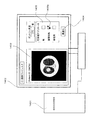
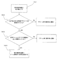
- FIG. 1 is a schematic diagram of a treatment planning apparatus according to an embodiment of the present invention. It is a block diagram which shows the interlock mechanism at the time of use of the short range applicator by one Embodiment of this invention. It is a flowchart figure which shows the function of the interlock mechanism at the time of use of the short range applicator by one Embodiment of this invention.
- FIG. 1 is a block diagram showing the overall configuration of a particle beam therapy system according to an embodiment of the present invention.
- the particle beam treatment system includes an irradiation compensation device (hereinafter, a short range applicator) 101 for a short range region and a proton beam irradiation device 102.
- a short range applicator for a short range region
- a proton beam irradiation device 102 for a proton beam irradiation device
- the proton beam irradiation apparatus 102 will be described as an example.
- the present invention can also be applied to a heavy particle beam irradiation apparatus using particles (carbon beam or the like) having a heavier mass than protons.
- the proton beam irradiation apparatus 102 includes a proton beam generation apparatus 103, a proton beam transport apparatus 104, and a rotary irradiation apparatus 105.
- the rotary irradiation device 105 having a rotating gantry will be described as an example, but the irradiation device may be a fixed type.
- the proton beam generator 103 includes an ion source 106, a pre-stage accelerator 107 (for example, a linear accelerator), and a synchrotron 108. Proton ions generated from the ion source 106 are first accelerated by the pre-stage accelerator 107. A proton beam (hereinafter referred to as a beam) emitted from the front accelerator 107 is accelerated to a predetermined energy by the synchrotron 108 and then emitted from the emission deflector 109 to the proton beam transport device 104. Finally, the beam is irradiated to the irradiation object through the rotary irradiation device 105.
- a beam emitted from the front accelerator 107
- the synchrotron 108 emitted from the front accelerator 107
- the beam is irradiated to the irradiation object through the rotary irradiation device 105.
- the rotary irradiation device 105 includes a rotary gantry (not shown) and an irradiation field forming device 110.
- the irradiation field forming device 110 installed in the rotating gantry rotates together with the rotating gantry.
- Part of the proton beam transport device 104 is attached to a rotating gantry.
- the synchrotron 108 is used as the proton beam accelerator, but a cyclotron or a linear accelerator may be used.
- the irradiation range is divided into minute regions (spots), and a beam is irradiated for each spot.
- a predetermined dose is applied to the spot, irradiation is stopped and the beam is scanned toward the next predetermined spot.
- a scanning electromagnet (not shown) mounted on the irradiation field forming apparatus 110 is used for the beam scanning in the horizontal direction.
- the irradiation field forming apparatus 110 scans the beam in the depth direction.
- the beam scanning in the depth direction is realized by changing the beam energy using a range shifter (not shown) mounted on the synchrotron 108 or the irradiation field forming device 110 or the like. Such a procedure is repeated to finally form a uniform dose distribution.
- the lateral dose distribution of the beam for each spot spreads in a Gaussian distribution with 1 ⁇ 3 mm to 20 mm on the isocenter plane.
- a straight line through which the center of the beam passes when the scanning electromagnet is not excited is defined as a beam axis.
- the intersection of the rotation axis of the rotary irradiation apparatus 105 and the beam axis is defined as an isocenter.
- the irradiation field forming device 110 is provided with a slot C201 for installing a short range applicator at the distal end portion thereof.
- FIG. 3 shows a schematic diagram of the short range applicator.
- the short range applicator 101 includes a support frame 301, an energy absorber 302, a first collimator 303 (hereinafter referred to as collimator A), and a second collimator 304 (hereinafter referred to as collimator B), and a beam to a short range region.
- collimator A first collimator 303
- collimator B second collimator 304
- the support frame 301 is provided with a slot A401 for storing the energy absorber 302 and the collimator A303, and a slot B402 for storing the collimator B304.
- the feature of the present invention is that the collimator of the short range applicator 101 is divided into a collimator A303 and a collimator B304 according to the function.
- the collimator In order to improve the penumbra, it is required to install the collimator as downstream as possible. However, since the beam diameter increases toward the downstream side, a collimator having a wider width and a larger weight is required for shielding the leaking beam. Therefore, the collimator is formed by a) collimator (collimator A303) having a leakage beam shielding function, and b) a shape of the beam in the lateral direction (perpendicular to the beam traveling direction) along the target shape.
- the above problem was solved by dividing into collimators (collimator B304) having a function to improve.
- the collimator A303 can suppress the lateral width by being arranged on the upstream side where the beam diameter is small, and contributes to the reduction in size and weight of the short-range applicator 101.
- the collimator B304 contributes to the improvement of the penumbra by being installed on the downstream side. Since the collimator B304 does not need a leakage beam shielding function, it does not need to be as wide as the collimator A303 as shown in FIG. Further, since the collimator is divided and attached to the support frame 301 individually, the weight of each part is reduced, and the burden on the operator is further reduced.
- a brass plate having a thickness of 20 mm is used for the collimator A in order to shield the beam leaking around the irradiation field.
- An opening 501 is provided in the central portion of the collimator A303 in order to shield only the beam leaked outside the irradiation field.
- the short range applicator 101 is used only when irradiating a region having a depth of 100 mm or less, a sufficient shielding effect can be obtained with the above specifications.
- the material and thickness of the collimator A303 are changed. (For example, if the short range applicator is applied to irradiation of deeper areas, the thickness must be increased).
- a 20 mm thick brass plate is used for the collimator B304. Used to shape the beam transverse shape along the target shape and improve the dose distribution penumbra. As shown in FIG. 5, a patient-specific opening 502 is opened in the collimator B304 in accordance with the target shape.
- the short range applicator 101 is used only when irradiating a region having a depth of 100 mm or less, so that the above specifications can provide a sufficient effect.
- the collimator B304 It is necessary to change the material and thickness.
- FIG. 6 shows a schematic diagram of the energy absorber 302.
- an ABS resin having a water equivalent thickness of 40 mm is used as the energy absorber 302.
- materials having different materials and water equivalent thickness may be used depending on the use conditions and the like.
- the energy absorber 302 of the present embodiment has a central portion protruding to the downstream side (having a central convex portion 601), and a structure integrated with the collimator A 303 as shown in FIG. 7. It has become.
- the energy absorber 302 may have a flat plate shape as shown in FIG.
- the energy absorber 302 is located on the upstream side as compared with FIGS. 6 and 7, there is a demerit in that the beam diameter is increased, but the energy absorber 302 can be easily manufactured and the short range applicator 101. The manufacturing cost is reduced.
- FIG. 9 and 10 show the installation procedure of the short range applicator 101 to the irradiation field forming apparatus 110.
- FIG. 9 first, the joint portion 901 of the support frame 301 is slid and attached to the slot C201 provided at the distal end portion of the irradiation field forming apparatus 110 from the lateral direction, and a fixture such as a bolt (not shown). ).
- the energy absorber 302, the collimator 303A, and the collimator B304 are removed from the support frame 301.
- the energy absorber 302 integrated with the collimator A303 is attached by sliding from the lateral direction with respect to the slot A401, and fixed with a fixture (not shown).
- the collimator B304 is attached by sliding it from the lateral direction with respect to the slot B402, and fixed with a fixture (not shown).
- the installation method and procedure of the short-range applicator 101 are assumed as described above.
- the energy absorber 302, the collimator A303, and the collimator B304 can be reliably fixed to the irradiation field forming device 110. A similar effect can be obtained.
- the same effect as in the present embodiment can be obtained even when the energy absorber 302, the collimator A303, and the collimator B304 are divided into a plurality of portions in the depth direction and are individually installed on the support frame 301. . Since the weight per part is reduced, the burden on the operator when installing the short-range applicator 101 is further reduced.
- the proton beam irradiation apparatus 101 can irradiate a beam in the range of 400 mm ⁇ 300 mm on the isocenter plane, when the general-purpose short range applicator 101 is adopted for all the assumed irradiation conditions, the energy absorber 302, the collimator A303, The collimator B304 must be enlarged. Therefore, in the particle beam therapy system according to the present embodiment, as shown in FIG. 12, a dedicated short range applicator 101 is provided for each treatment site (for example, the head and neck, the spine, etc.). The irradiation field shape required for radiation therapy is generally determined for each treatment site. Therefore, if the short range applicator 101 has a dedicated shape for each treatment site, the short range applicator 101 can be downsized to a necessary and sufficient size for each treatment. The burden on the operator can be further reduced when the short range applicator 101 is installed.
- the treatment planning apparatus 1401 displays an operation screen 1402 for selecting whether or not the short range applicator 101 is used and the type of the short range applicator 101 to be used, and the displayed operation screen.
- the presence / absence of use of the short range applicator 101 selected in 1402 and the type of the short range applicator 101 to be used are recorded in a prescription and output to the irradiation control device 1503 (see FIG. 15).
- the treatment planning apparatus 1401 uses a short range that uses the arrangement of the spots that can be used and the emitted beam from the proton beam generator 103 that can be used during the optimization calculation.
- the range is limited according to the applicator 101.
- the treatment planning device 1401 includes information on the short-range applicator 101 having a dedicated shape for each treatment site, whether or not the short-range applicator 101 selected on the operation screen 1402 is used, and the short-range applicator to be used. 101 types are recorded.
- the operator inputs X-ray CT image information of the irradiated object to the treatment planning apparatus 1401 and displays it on the operation screen 1402 (step 1301).
- the operator designates the irradiation direction (that is, the angle of the rotating gantry) and the target range using a user interface (not shown) such as a mouse while confirming the CT image 1403 on the operation screen 1402 (Ste 1302).
- a user interface not shown
- the same effect can be obtained as long as the image can confirm the internal structure of the irradiated object.
- the treatment planning apparatus gives a uniform and sufficient amount of dose within the designated target when the operator clicks the optimization button 1404 on the operation screen 1402.
- An appropriate spot arrangement, irradiation beam energy and beam irradiation amount for each spot are calculated, and the calculation result is output as a prescription (step 1303).
- the operator checks the corresponding short range applicator use check box 1405 on the operation screen 1402 (step 1304).
- the treatment planning apparatus 1401 can arrange the spots that can be used in the optimization calculation performed when the prescription is created. Is limited to 200 mm ⁇ 200 mm.
- the usable outgoing beam from the proton beam generator 103 is limited to a range of 100 mm or less.
- a prescription in which the spot arrangement is limited to 200 mm ⁇ 200 mm and the beam range is limited to 100 mm or less is output from the treatment planning device 1401 (step 1303).
- the prescription also includes information on the type of short-range applicator (for example, for head and neck, for spine).
- the treatment planning apparatus 1401 of this embodiment has a function of preventing erroneous irradiation when the short-range applicator 101 is installed.
- the short range applicator 101 of the present embodiment has a dedicated shape for each treatment site for miniaturization.
- the proton beam irradiation apparatus 102 has a performance capable of irradiating a beam in a range of 400 mm ⁇ 300 mm on the isocenter surface, a function to prevent the beam irradiation to the outside of the collimator A303 is essential.
- the spot arrangement limit for the short range applicator with a width of 250 mm ⁇ 250 mm is set to 200 mm ⁇ 200 mm or less, but it is necessary to change the spot according to the beam diameter and leakage dose criteria.
- the thickness of the collimator A303 and the collimator B304 is 20 mm. Since the proton beam irradiation device 102 has a performance capable of irradiating a beam with a range of up to 300 mm that can easily pass through this thickness, a high-energy beam due to an operator's mistake or the like, as in this embodiment, In other words, a function for preventing the irradiation of a long-range beam is essential. In this embodiment, the range is limited to 100 mm or less, but it is necessary to change the range according to the thickness of the energy absorber 302, the collimator A303, and the collimator B304.
- the proton beam irradiation device 102 and the short range applicator 101 are also provided with an interlock mechanism for preventing erroneous irradiation.
- a sensor 1501 is provided in the slot C201 at the tip of the irradiation field forming device 110, and an IC chip (first sensor) 1502 is provided in the connection portion 901 of the support frame 301.
- the IC chip 1502 stores information on the type of the short range applicator 101 (for example, for head and neck, for spine, etc.).
- the sensor 1501 reads the information of the IC chip 1502 and transmits it to the irradiation control device 1503.
- the slot A 401 and the slot B 402 are provided with a limit switch (second sensor) 1504 in order to monitor the attachment / detachment status of the energy absorber 302, the collimator A 303, and the collimator B 304.
- a signal is output from the limit switch 1504 to the irradiation control device 1503 via the sensor 1501 only when the energy absorber 302, the collimator A303, and the collimator B304 are correctly installed on the support frame 301.
- FIG. 16 is a flowchart showing the operation of the interlock function.
- the operator operates to input a prescription from the treatment planning device 1401 to the irradiation control device 1503 (step 1601).
- the irradiation control device 1503 reads the presence / absence of application of the short range applicator 101 in the current beam irradiation and the type of the short range applicator 101 to be applied from the prescription. Further, the irradiation control device 1503 collates the read information with the information of the IC chip 1502 output from the sensor 1501 of the irradiation field forming device 110 (step 1602).
- the irradiation control apparatus 1503 After confirming that the same short range applicator 101 as the prescription is installed in the irradiation field forming apparatus 110, the irradiation control apparatus 1503 confirms that a signal is output from all the limit switches 1504 (step 1603). . After confirming that signals are output from all limit switches 1504, the irradiation control device 1503 transmits a beam irradiation start permission signal to the proton beam irradiation device 102 (step 1604). In this embodiment, the IC chip 1502 and the sensor 1501 are used. However, the same effect can be obtained as long as the type of the short range applicator 101 can be identified. Further, although the limit switch 1504 is used in the present embodiment, the same effect can be obtained if the method can monitor the attachment / detachment status of each device.
- an irradiation object is fixed to a patient couch (not shown) provided in a treatment room (not shown).
- the patient couch moves in the 6-axis direction, and the operator can move the irradiated object to an arbitrary position.
- a laser marker not shown
- an X-ray imaging apparatus not shown
- the short range applicator 101 is installed in the irradiation field forming apparatus 110 according to the above-described procedure, and the rotating gantry is rotated to the same angle as that at the time of treatment planning. After the work in the treatment room, the operator moves to an irradiation control room (not shown). Finally, a prescription created in advance using the treatment planning device 1401 is input to the irradiation control device 1503, and beam irradiation is started. After confirming that the short range applicator 101 is correctly installed in the irradiation field forming apparatus 110, the irradiation control apparatus 1503 transmits a beam irradiation permission signal to the proton beam irradiation apparatus 102. After receiving the beam irradiation permission signal, the proton beam irradiation apparatus 102 sequentially irradiates each spot with a beam based on the information described in the prescription according to the procedure of the scanning irradiation method described above.
- the cost is increased, the penumbra is increased outside the short range region, and the operator is burdened. Improve the penumbra in the short range without increasing.
- the width of the Bragg peak is increased by the application of the short range applicator, the number of spots in the depth direction necessary for forming the enlarged Bragg peak is reduced, and the dose rate is improved.
- the robustness with respect to the dose uniformity within the target is improved by the expansion of the Bragg peak width.
- Irradiation compensation device short range applicator
- 102 ... proton beam irradiation device
- 103 ... proton generator
- 104 ... Proton beam transport device
- 105 Rotary irradiation device
- 106 ... ion source
- 107 front accelerator
- 108 ... Synchrotron
- 109 ... Outgoing deflector
- 110 ... Irradiation field forming device, 201 ... slot C, 301 ... Support frame, 302 ... energy absorber, 303 ... Collimator A, 304 ... Collimator B 401 ... slot A, 402 ... slot B, 501 ... opening of collimator A, 502 ... opening of collimator B, 601 ...
Landscapes
- Health & Medical Sciences (AREA)
- Engineering & Computer Science (AREA)
- Biomedical Technology (AREA)
- Pathology (AREA)
- Nuclear Medicine, Radiotherapy & Molecular Imaging (AREA)
- Radiology & Medical Imaging (AREA)
- Life Sciences & Earth Sciences (AREA)
- Animal Behavior & Ethology (AREA)
- General Health & Medical Sciences (AREA)
- Public Health (AREA)
- Veterinary Medicine (AREA)
- Radiation-Therapy Devices (AREA)
Abstract
本発明の粒子線治療システムはエネルギー吸収体、第一のコリメータ及び第二のコリメータで構成される短飛程領域への照射補償装置を備えた。前記照射補償装置は前記エネルギー吸収体、第一のコリメータ及び第二のコリメータの着脱機構を備えることを特徴とする。第一のコリメータは、ビーム径の小さな上流側に配置することで前記補償装置の横幅を抑えることができ、短前記補償装置の小型・軽量化に寄与する。第二のコリメータは、下流側に設置することでペナンブラの改善に寄与する。
Description
本発明は、粒子線治療システムに関する。
粒子線治療では、スキャニング照射法が普及しつつある。スキャニング照射法では、標的を微少領域(以下、スポット)に分割して考え、スポット毎に細径のビームを照射する。あるスポットに既定の線量が付与されると、ビームの照射を停止し、次のスポットに向けてビームを走査する。ビームをビーム進行方向(以下、深さ方向)と垂直な方向(以下、横方向)に走査する場合は、走査電磁石を用いる。ある深さについてすべてのスポットに既定線量が付与されると、ビームを深さ方向に走査する。ビームを深さ方向に走査する場合は、加速器もしくはレンジシフタでビームのエネルギーを変更する。最終的に、全てのスポット、即ち標的全体に一様な線量が付与される。
スポット毎のビームは、横方向に対して2次元ガウス分布状の広がりを持つ。1σはアイソセンタ面において3~20mm程度であり、高エネルギーのビームほど小さい。低エネルギーのビームは多重クーロン散乱による単位距離あたりの角度発散量が大きく、照射野形成装置内を通過する過程でビーム径が増大する。
従って、被照射体の表面から浅い位置(以下、短飛程領域)にある標的に対しては、線量分布形成に低エネルギーのビームを用いるため、ペナンブラが増加する。ペナンブラは標的外又は標的と正常組織との境界近傍の領域において付与線量が80%から20%に低下するまでの横方向の距離を示し、ビーム径と正の相関を持つ。ここで、標的中心近傍の付与線量を100%とした。ペナンブラが小さいほど標的形状に合致した高精細な線量分布といえる。
このような課題に対して、非特許文献1では被照射体の上流にエネルギー吸収体を設置する手法が提示されている。この手法では、短飛程領域の標的に対しても高エネルギーのビームを照射し、エネルギー吸収体により被照射体への入射直前にビームエネルギーを低下させる。低エネルギー状態でのビームのドリフト距離を抑えられるため、ビーム径を抑制し、ペナンブラを改善できる。また、非特許文献2には、コリメータを用いて標的外に入射するビームを遮蔽し、ペナンブラの改善を図る手法が提示されている。
U. Titt, et al., "Adjustment of the lateral and longitudinal size of scanned proton beam spot using a pre-absorber to optimize penumbrae and delivery efficiency" Phys. Med Biol. 55 (2010) 7097-7106.
M. Bues, et al., "Therapeutic step and shoot proton beam spot-scanning with a multi-leaf collimator: a monte carlo study" Radiat. Prot. Dosim. 115 164-9.
非特許文献1のエネルギー吸収体と非特許文献2のコリメータを併用すると、短飛程領域へのスキャニング照射においてペナンブラをさらに改善できると考えられる。しかしながら、照射野形成装置へのこれら2つの装置の着脱方法について課題があった。被照射体の表面から深い位置、即ち短飛程領域外の標的に対してはこれら2つの装置を使用しないため、ビーム通過領域から取り除く必要がある。
エネルギー吸収体の駆動装置やマルチリーフコリメータを照射野形成装置内に備えると、装置の着脱が自動化され、操作者の負担を軽減できる。しかしながら、照射野形成装置が深さ方向に大型化するため、照射野形成装置内でのビームのドリフト距離が増加し、高エネルギー条件においてビーム径が増大する。従って、短飛程領域への照射ではエネルギー吸収体及びコリメータの働きによってペナンブラを改善できるものの、短飛程領域外への照射では逆にペナンブラが増加する。また、照射野形成装置の大型化に伴って回転ガントリーも大型化し、粒子線治療システムのコストが増大する。
照射野形成装置の先端部分にアプリケータの設置治具を設け、操作者が手動でアプリケータの着脱を実施する場合には、こうした課題を解決できる。ここで、エネルギー吸収体とコリメータで構成される短飛程領域への照射補償装置をアプリケータと称する。しかしながら、スキャニング照射法により照射野を形成する照射野形成装置は、一般的に横方向に対して400mm×300mmの範囲にビームを走査可能であり、こうした仕様に対応するアプリケータは大型且つ重量物となる。従って、照射野形成装置へのアプリケータの手動着脱は操作者の多大な負担となる。
本発明は、コストの増加、短飛程領域外でのペナンブラ増加、操作者の負担増加を伴うことなく、短飛程領域でのペナンブラを改善することができるスキャニング照射法により照射野を形成する照射野形成装置を備えた粒子線治療システムを提供することを目的とする。
上記課題を解決するため、本発明の粒子線治療システムは、スキャニング照射法により照射野を形成する照射野形成装置と、エネルギー吸収体、第一のコリメータ、第二のコリメータ、前記エネルギー吸収体、前記第一のコリメータ及び前記第二のコリメータの着脱機構を有する短飛程領域への照射補償装置とを備え、前記照射野形成装置は、前記照射補償装置の着脱機構を有したことを特徴とする。
本発明によれば、スキャニング照射法により照射野を形成する照射野形成装置を備えた粒子線治療システムにおいて、コストの増加、短飛程領域外でのペナンブラ増加、操作者の負担増加を伴うことなく、短飛程領域でのペナンブラを改善することができる。
以下、図1乃至図16を用いて、本発明の一実施形態による粒子線治療システムの構成及び動作について説明する。図1は、本発明の一実施形態による粒子線治療システムの全体構成を示すブロック図である。粒子線治療システムは、短飛程領域への照射補償装置(以下、短飛程アプリケータ)101と、陽子線照射装置102とを備えている。本実施例では、陽子線照射装置102を例に説明するが、本発明は陽子より質量の重い粒子(炭素線など)を用いた重粒子線照射装置にも適用できる。
図1に示すように、陽子線照射装置102は、陽子線発生装置103,陽子線輸送装置104及び回転式照射装置105を有する。なお、本実施例では回転ガントリーを備える回転式照射装置105を例に説明するが、照射装置は固定式であってもよい。
陽子線発生装置103は、イオン源106,前段加速器107(例えば、直線加速器)及びシンクロトロン108を有する。イオン源106で発生した陽子イオンは、まず、前段加速器107で加速される。前段加速器107から出射した陽子線(以下、ビーム)は、シンクロトロン108で所定のエネルギーまで加速された後、出射デフレクタ109から陽子線輸送装置104に出射される。最終的に、ビームは、回転式照射装置105を経て被照射体に照射される。回転式照射装置105は、回転ガントリー(図示せず)及び照射野形成装置110を有する。回転ガントリーに設置された照射野形成装置110は、回転ガントリーと共に回転する。陽子線輸送装置104の一部は、回転ガントリーに取り付けられている。本実施例では、陽子線の加速装置としてシンクロトロン108を採用したが、サイクロトロンや直線加速器であってもよい。
次に、本実施例の照射野形成装置110によって実現される、スキャニング照射法の概要を説明する。スキャニング照射法では、照射範囲を微少領域(スポット)に分割し、スポット毎にビームを照射する。スポットに既定線量が付与されると、照射を停止して次の既定スポットに向けてビームを走査する。横方向へのビーム走査には照射野形成装置110に搭載した走査電磁石(図示せず)を用いる。ある深さについてすべてのスポットに既定線量を付与すると、照射野形成装置110は深さ方向にビームを走査する。シンクロトロン108もしくは照射野形成装置110等に搭載したレンジシフタ(図示せず)を用いてビームのエネルギーを変更することで、深さ方向へのビーム走査は実現される。このような手順を繰り返し、最終的に一様な線量分布が形成される。
スポット毎のビームの横方向線量分布は、アイソセンタ面において1σ=3mm~20mmのガウス分布状に広がっている。本実施例では、走査電磁石を励磁しない状態においてビームの中心が通過する直線をビーム軸と定義する。また、回転式照射装置105の回転軸とビーム軸との交点をアイソセンタと定義する。
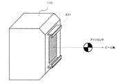
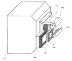
図2に示すように、照射野形成装置110の先端部分には短飛程アプリケータ設置用のスロットC201が備わる。
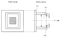
図3に短飛程アプリケータの概略図を示す。短飛程アプリケータ101は支持フレーム301、エネルギー吸収体302、第一のコリメータ303(以下、コリメータA)、第二のコリメータ304(以下、コリメータB)で構成され、短飛程領域へのビーム照射時において、ペナンブラを改善する目的で照射野形成装置110に設置される。図4に示すように、支持フレーム301には、エネルギー吸収体302及びコリメータA303を納めるスロットA401、コリメータB304を納めるスロットB402が備わる。
本発明の特徴は、機能に応じて短飛程アプリケータ101のコリメータをコリメータA303とコリメータB304に分割したことにある。ペナンブラを改善するには、コリメータをできるだけ下流側に設置する事が求められる。しかしながら、下流側ほどビーム径が増大するため、漏えいビームの遮蔽にはより横幅が広く、重量の大きなコリメータが必要になる。そこで、コリメータをa)漏えいビームの遮蔽機能を持ったコリメータ(コリメータA303)と、b)標的形状に沿ってビームの横方向(ビーム進行方向に対して垂直な方向)形状を成型し、ペナンブラを改善する機能を持ったコリメータ(コリメータB304)に分割し、上記課題を解決した。コリメータA303は、ビーム径の小さな上流側に配置することで横幅を抑えることができ、短飛程アプリケータ101の小型・軽量化に寄与する。コリメータB304は、下流側に設置することでペナンブラの改善に寄与する。コリメータB304には漏えいビームの遮蔽機能が不要なため、図3にも示すようにコリメータA303ほどの横幅は必要ない。また、コリメータが分割され、支持フレーム301に対して個別に取り付ける構造となることから、パーツ毎の重量が減少し、操作者の負担がさらに軽減される。
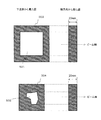
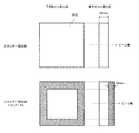
図5を用いてコリメータA303及びコリメータB304の構造を説明する。照射野周辺に漏えいするビームを遮蔽するため、コリメータAには厚さ20mmの真鍮板を用いる。照射野外に漏えいしたビームのみを遮蔽するため、コリメータA303の中心部分には開口部501が設けられている。本実施例では、深さ100mm以下の領域を照射する場合のみ短飛程アプリケータ101を使用するため上記仕様で十分な遮蔽効果が得られるが、使用条件によってはコリメータA303の材質及び厚みを変更する必要がある(例えば、より深い領域の照射にも短飛程アプリケータを適用する場合には、厚みを増やす必要がある)。
コリメータA303と同様に、コリメータB304には厚さ20mmの真鍮板を用いる。標的形状に沿ってビームの横方向形状を成型し、線量分布のペナンブラを改善する目的で使用される。図5に示すように、標的形状に合わせてコリメータB304には患者固有の開口部502が開けられる。コリメータA303と同様に、本実施例では、深さ100mm以下の領域を照射する場合のみ短飛程アプリケータ101を使用するため上記仕様で十分な効果が得られるが、使用条件によってはコリメータB304の材質及び厚みを変更する必要がある。
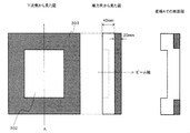
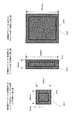
図6はエネルギー吸収体302の概略図を示す。本実施例では、エネルギー吸収体302として水等価厚40mmのABS樹脂を用いるが、使用条件等に応じて材質、水等価厚の異なるものを用いてもよい。また、図6に示すように、本実施例のエネルギー吸収体302は中心部分が下流側にせり出しており(中心凸部601を有する)、図7に示すようにコリメータA303と一体化する構造となっている。ビーム径を低減するには、低エネルギー状態でのビームのドリフト距離を短縮するためエネルギー吸収体302をできるだけ下流側に設置することが有効である。ただし、エネルギー吸収体302を図8のような平板状の形態としても良い。この場合、図6、図7と比較してエネルギー吸収体302が上流側に位置するため、ビーム径が増加するデメリットはあるものの、エネルギー吸収体302の製作が容易になり短飛程アプリケータ101の製造コストが低下する。
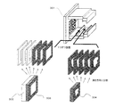
図9及び図10を用いて、照射野形成装置110への短飛程アプリケータ101の設置手順を示す。図9に示すように、まず、照射野形成装置110の先端部分に備わるスロットC201に対して、支持フレーム301のジョイント部901を横方向からスライドさせて取り付け、ボルト等の固定具(図示せず)で固定する。このとき、エネルギー吸収体302、コリメータ303A及びコリメータB304は支持フレーム301から取り外されている。次に、図10に示すようにコリメータA303と一体構造のエネルギー吸収体302をスロットA401に対して横方向からスライドさせて取り付け、固定具(図示せず)で固定する。最後に、コリメータB304をスロットB402に対して横方向からスライドさせて取り付け、固定具(図示せず)で固定する。
本実施例では、短飛程アプリケータ101の設置方法及び手順を上記のように想定したが、エネルギー吸収体302、コリメータA303及びコリメータB304を照射野形成装置110に確実に固定できる方法であれば、同様の効果が得られる。
図11に示すように、エネルギー吸収体302、コリメータA303及びコリメータB304を深さ方向に複数に分割し、支持フレーム301に対して個別に設置する構造としても本実施例と同様の効果が得られる。1パーツあたりの重量が減るため、短飛程アプリケータ101設置時における操作者の負担がさらに軽減する。
陽子線照射装置101はアイソセンタ面において400mm×300mmの範囲にビームを照射できるため、想定される全照射条件に対して汎用の短飛程アプリケータ101を採用すると、エネルギー吸収体302、コリメータA303及びコリメータB304を大型化しなくてはならない。そこで、本実施例の粒子線治療システムでは、図12に示すように治療部位毎(例えば、頭頸部、背骨など)に専用形状の短飛程アプリケータ101を備える。放射線治療で要求される照射野形状は、治療部位毎に概ね決まっている。従って、短飛程アプリケータ101を治療部位毎の専用形状とすれば、短飛程アプリケータ101を各治療に対し必要十分なサイズに小型化できる。短飛程アプリケータ101設置時において操作者の負担をさらに低減できる。
図13に示す治療計画のフローチャート及び図14に示す本実施例の粒子線治療システムに備わる治療計画装置の概要図を用いて、短飛程アプリケータ101適用時における治療計画の手順を示す。図14に示すように、治療計画装置1401は、短飛程アプリケータ101の使用の有無及び使用する短飛程アプリケータ101の種類を選択するための操作画面1402を表示し、表示した操作画面1402で選択された短飛程アプリケータ101の使用の有無及び使用する短飛程アプリケータ101の種類を処方箋に記録して照射制御装置1503(図15参照)に出力する。また、治療計画装置1401は、短飛程アプリケータ101を使用する場合、最適化計算の際に、使用できるスポットの配置および使用できる陽子線発生装置103からの出射ビームを、使用する短飛程アプリケータ101に応じた範囲に制限する。更に、治療計画装置1401は、治療部位毎に専用形状の短飛程アプリケータ101に関する情報や、操作画面1402で選択された短飛程アプリケータ101の使用の有無及び使用する短飛程アプリケータ101の種類を記録する。
まず、操作者は治療計画装置1401に被照射体のX線CT画像情報を入力し、操作画面1402に表示する(ステップ1301)。次に、操作者は操作画面1402上のCT画像1403を確認しながら、マウス等のユーザーインターフェース(図示せず)を用いて照射方向(即ち、回転ガントリーの角度)及び標的の範囲を指定する(ステップ1302)。本実施例ではX線CT画像情報を用いたが、被照射体の内部構造を確認可能な画像であれば同様の効果が得られる。
まず、操作者は治療計画装置1401に被照射体のX線CT画像情報を入力し、操作画面1402に表示する(ステップ1301)。次に、操作者は操作画面1402上のCT画像1403を確認しながら、マウス等のユーザーインターフェース(図示せず)を用いて照射方向(即ち、回転ガントリーの角度)及び標的の範囲を指定する(ステップ1302)。本実施例ではX線CT画像情報を用いたが、被照射体の内部構造を確認可能な画像であれば同様の効果が得られる。
短飛程アプリケータ101を使用しない場合、操作者が操作画面上1402の最適化ボタン1404をクリックすることで、治療計画装置は指定された標的内に一様且つ十分な量の線量を付与するための適切なスポットの配置、各スポットへの照射ビームエネルギー、ビーム照射量を算出し、算出結果を処方箋として出力する(ステップ1303)。
一方、短飛程アプリケータ101を使用する場合、操作者は操作画面1402上の該当する短飛程アプリケータ使用チェックボックス1405をチェックする(ステップ1304)。例えば、コリメータAの横幅250mm×250mmである頭頸部用短飛程アプリケータの欄1405aにチェックを入れると、治療計画装置1401は処方箋の作成時に実施する最適化計算の際、使用できるスポットの配置を200mm×200mm以内に制限する。また、最適化計算の際、使用できる陽子線発生装置103からの出射ビームを飛程100mm以下に制限する。その後、最適化ボタン1404をクリックすると、治療計画装置1401からは、スポットの配置が200mm×200mm以内、ビーム飛程が100mm以下に制限された処方箋が出力される(ステップ1303)。また、処方箋には短飛程アプリケータの種類に関する情報(例えば、頭頸部用、背骨用など)も記載される。
このように、本実施例の治療計画装置1401は、短飛程アプリケータ101設置時の誤照射を防止する機能を有する。前述のように、本実施例の短飛程アプリケータ101は小型化のため治療部位毎に専用形状としている。しかしながら、陽子線照射装置102はアイソセンタ面において400mm×300mmの範囲にビーム照射可能な性能を有しているため、コリメータA303の外側への万が一のビーム照射を防止する機能が必須である。なお、本実施例では横幅250mm×250mmの短飛程アプリケータに対してスポットの配置制限を200mm×200mm以内としたが、ビーム径や漏えい線量のクライテリアに応じて変更する必要がある。
また、本実施例ではコリメータA303およびコリメータB304の厚みを20mmとしている。陽子線照射装置102はこの厚みを容易に透過可能な飛程300mmまでのビームを照射可能な性能を有しているため、本実施例のように、操作者のミス等により高エネルギーのビーム、即ち飛程の長いビームが照射されてしまう事を防止する機能は必須である。本実施例では飛程の制限を100mm以下としたが、エネルギー吸収体302、コリメータA303及びコリメータB304の厚みによって変更する必要がある。
本実施例では、陽子線照射装置102及び短飛程アプリケータ101も誤照射防止のインターロック機構を備える。図15のブロック図に示すように、照射野形成装置110先端部のスロットC201にはセンサ1501、支持フレーム301の接続部901にはICチップ(第一センサ)1502が備わる。ICチップ1502には短飛程アプリケータ101の種類(例えば、頭頸部用、背骨用など)に関する情報が記録されている。前述の手順に従って支持フレーム301を照射野形成装置110に接続すると、センサ1501がICチップ1502の情報を読み取って照射制御装置1503に送信する。一方、スロットA401及びスロットB402には、エネルギー吸収体302、コリメータA303及びコリメータB304の着脱状況を監視するため、リミットスイッチ(第二センサ)1504が備わる。リミットスイッチ1504からは、エネルギー吸収体302、コリメータA303及びコリメータB304が支持フレーム301に正しく設置されている場合にのみ、センサ1501を介して照射制御装置1503に対して信号が出力される。
図16は、上記インターロック機能の働きを示すフローチャート図である。まず、被照射体へのビーム照射を実施するため、操作者が、治療計画装置1401から照射制御装置1503に処方箋を入力するよう操作する(ステップ1601)。すると、照射制御装置1503は処方箋から今回のビーム照射における短飛程アプリケータ101適用の有無と、適用予定の短飛程アプリケータ101の種類を読み取る。さらに、照射制御装置1503は読み取った前記情報を照射野形成装置110のセンサ1501から出力されたICチップ1502の情報と照合する(ステップ1602)。処方箋と同じ短飛程アプリケータ101が照射野形成装置110に設置されていることを確認したのち、照射制御装置1503は全リミットスイッチ1504から信号が出力されていることを確認する(ステップ1603)。全リミットスイッチ1504から信号が出力されている事を確認したのち、照射制御装置1503は陽子線照射装置102に対してビーム照射開始許可信号を送信する(ステップ1604)。本実施例ではICチップ1502とセンサ1501を用いたが、短飛程アプリケータ101の種類を識別できる方法であれば同様の効果が得られる。また、本実施例ではリミットスイッチ1504を用いたが、各機器の着脱状況を監視できる方法であれば同様の効果が得られる。
本発明の粒子線治療システムを用いた短飛程領域へのビーム照射の手順を示す。まず、治療室(図示せず)に備わる患者カウチ(図示せず)に被照射体を固定する。患者カウチは6軸方向に可動し、操作者により被照射体を任意の位置に移動できる。次に、回転ガントリーに取り付けられたレーザーマーカ(図示せず)やX線撮影装置(図示せず)により、被照射体の現在位置と治療計画時の位置とのズレ量を算出し、患者カウチを動作させてズレ量を十分低減させる。さらに、前述の手順に従って短飛程アプリケータ101を照射野形成装置110に設置し、治療計画時と同じ角度まで回転ガントリーを回転させる。上記治療室での作業後、操作者は照射制御室(図示せず)に移動する。最後に、治療計画装置1401を用いて事前に作成した処方箋を照射制御装置1503に入力し、ビーム照射を開始する。短飛程アプリケータ101が正しく照射野形成装置110に設置されている事を確認したのち、照射制御装置1503は陽子線照射装置102にビーム照射許可信号を送信する。ビーム照射許可信号を受信したのち、前述のスキャニング照射法の手順に従い、陽子線照射装置102は処方箋に記載された情報に基づいて各スポットに対して順番にビームを照射する。
このように、本発明によれば、スキャニング照射法により照射野を形成する照射野形成装置を備えた粒子線治療システムにおいて、コストの増加、短飛程領域外でのペナンブラ増加、操作者の負担増加を伴うことなく、短飛程領域でのペナンブラを改善する。また、短飛程アプリケータの適用によりブラッグピークの幅が増加するため、拡大ブラッグピーク形成に必要な深さ方向へのスポット数が減少し、線量率が向上する。さらにまた、ブラッグピーク幅の拡大により、標的内線量一様度に対するロバスト性が向上する。
なお、本発明は上記の実施形態に限られず、種々の変形、応用が可能なものである。
101…照射補償装置(短飛程アプリケータ)、
102…陽子線照射装置、
103…陽子線発生装置、
104…陽子線輸送装置、
105…回転式照射装置、
106…イオン源、
107…前段加速器、
108…シンクロトロン、
109…出射デフレクタ、
110…照射野形成装置、
201…スロットC、
301…支持フレーム、
302…エネルギー吸収体、
303…コリメータA、
304…コリメータB、
401…スロットA、
402…スロットB、
501…コリメータAの開口部、
502…コリメータBの開口部、
601…エネルギー吸収体の中心凸部、
901…支持フレームのジョイント部、
1301…治療計画の手順、
1302…治療計画の手順、
1303…治療計画の手順、
1304…治療計画の手順、
1401…治療計画装置、
1402…操作画面、
1403…被照射体のX線CT画像、
1404…最適化ボタン、
1405…短飛程アプリケータ使用の有無を示すチェックボックス、
1405a…使用する短飛程アプリケータの種類を示すチェックボックス、
1501…センサ、
1502…ICチップ、
1503…照射制御装置、
1504…リミットスイッチ、
1601…ビーム照射までの手順、
1602…ビーム照射までの手順、
1603…ビーム照射までの手順、
1604…ビーム照射までの手順。
102…陽子線照射装置、
103…陽子線発生装置、
104…陽子線輸送装置、
105…回転式照射装置、
106…イオン源、
107…前段加速器、
108…シンクロトロン、
109…出射デフレクタ、
110…照射野形成装置、
201…スロットC、
301…支持フレーム、
302…エネルギー吸収体、
303…コリメータA、
304…コリメータB、
401…スロットA、
402…スロットB、
501…コリメータAの開口部、
502…コリメータBの開口部、
601…エネルギー吸収体の中心凸部、
901…支持フレームのジョイント部、
1301…治療計画の手順、
1302…治療計画の手順、
1303…治療計画の手順、
1304…治療計画の手順、
1401…治療計画装置、
1402…操作画面、
1403…被照射体のX線CT画像、
1404…最適化ボタン、
1405…短飛程アプリケータ使用の有無を示すチェックボックス、
1405a…使用する短飛程アプリケータの種類を示すチェックボックス、
1501…センサ、
1502…ICチップ、
1503…照射制御装置、
1504…リミットスイッチ、
1601…ビーム照射までの手順、
1602…ビーム照射までの手順、
1603…ビーム照射までの手順、
1604…ビーム照射までの手順。
Claims (6)
- 粒子線治療システムであって、
スキャニング照射法により照射野を形成する照射野形成装置と、
エネルギー吸収体、第一のコリメータ、第二のコリメータ、前記エネルギー吸収体、前記第一のコリメータ及び前記第二のコリメータの着脱機構を有する短飛程領域への照射補償装置とを備え、
前記照射野形成装置は、前記照射補償装置の着脱機構を有した
ことを特徴とする粒子線治療システム。 - 請求項1に記載の粒子線治療システムにおいて、
横方向の形状が異なる少なくとも2種類以上の前記エネルギー吸収体、前記第一のコリメータ及び前記第二のコリメータを有する前記照射補償装置を更に備えた
ことを特徴とする粒子線治療システム。 - 請求項1又は請求項2に記載の粒子線治療システムにおいて、
処方箋作成時において、最適化計算の際に前記照射補償装置の使用の有無及び使用する前記照射補償装置の種類を選択し、この選択した前記照射補償装置の使用の有無及び使用する前記照射補償装置の種類を前記処方箋に記録して出力する治療計画装置を更に備えた
ことを特徴とする粒子線治療システム。 - 請求項3に記載の粒子線治療システムにおいて、
前記照射補償装置を使用することが選択された場合、スポットを配置可能な範囲及び使用可能な出射ビームエネルギーを前記照射補償装置毎に制限して最適化計算する前記治療計画装置を更に備えた
ことを特徴とする粒子線治療システム。 - 請求項3又は請求項4に記載の粒子線治療システムにおいて、
陽子線照射装置と、
前記照射補償装置の着脱状況及び設置された前記照射補償装置の種類を監視して照射制御装置に出力する第一センサを有する前記照射野形成装置と、
前記治療計画装置から出力された前記処方箋が入力されると、入力された前記処方箋に記録された、最適化計算の際に選択した前記照射補償装置の使用の有無及び前記照射補償装置の種類の情報と、前記第一センサから出力された前記照射野形成装置における前記照射補償装置の着脱状況及び設置した前記照射補償装置の種類の情報とを照合し、両者が一致する場合のみ前記陽子線照射装置に対してビーム照射を許可する前記照射制御装置とを更に備えた
ことを特徴とする粒子線治療システム。 - 請求項5に記載の粒子線治療システムにおいて、
前記エネルギー吸収体、前記第一のコリメータ及び前記第二のコリメータの着脱状況を監視して前記照射制御装置に出力する第二センサを有する前記照射補償装置と、
前記処方箋に前記照射補償装置を使用することが記録され、且つ前記エネルギー吸収体、前記第一のコリメータ及び前記第二のコリメータがすべて前記照射補償装置に設置されていることを前記第二センサから出力された情報より認識した場合のみ前記陽子線照射装置に対してビーム照射を許可する前記照射制御装置とを更に備えた
ことを特徴とする粒子線治療システム。
Priority Applications (3)
| Application Number | Priority Date | Filing Date | Title |
|---|---|---|---|
| US14/763,595 US9492684B2 (en) | 2013-01-29 | 2013-10-10 | Particle therapy system |
| CN201380071654.7A CN105050659B (zh) | 2013-01-29 | 2013-10-10 | 粒子束治疗系统 |
| EP13873829.9A EP2952225B1 (en) | 2013-01-29 | 2013-10-10 | Particle-beam therapy system |
Applications Claiming Priority (2)
| Application Number | Priority Date | Filing Date | Title |
|---|---|---|---|
| JP2013-014153 | 2013-01-29 | ||
| JP2013014153A JP6066478B2 (ja) | 2013-01-29 | 2013-01-29 | 粒子線治療システム |
Publications (1)
| Publication Number | Publication Date |
|---|---|
| WO2014119050A1 true WO2014119050A1 (ja) | 2014-08-07 |
Family
ID=51261786
Family Applications (1)
| Application Number | Title | Priority Date | Filing Date |
|---|---|---|---|
| PCT/JP2013/077640 Ceased WO2014119050A1 (ja) | 2013-01-29 | 2013-10-10 | 粒子線治療システム |
Country Status (5)
| Country | Link |
|---|---|
| US (1) | US9492684B2 (ja) |
| EP (1) | EP2952225B1 (ja) |
| JP (1) | JP6066478B2 (ja) |
| CN (1) | CN105050659B (ja) |
| WO (1) | WO2014119050A1 (ja) |
Cited By (2)
| Publication number | Priority date | Publication date | Assignee | Title |
|---|---|---|---|---|
| CN111053977A (zh) * | 2019-12-20 | 2020-04-24 | 上海联影医疗科技有限公司 | 多叶光栅和放射治疗装置 |
| JP2020192085A (ja) * | 2019-05-28 | 2020-12-03 | 株式会社日立製作所 | 粒子線治療システムおよび粒子線治療システムの操作画面更新方法 |
Families Citing this family (21)
| Publication number | Priority date | Publication date | Assignee | Title |
|---|---|---|---|---|
| EP3049151B1 (en) | 2013-09-27 | 2019-12-25 | Mevion Medical Systems, Inc. | Particle beam scanning |
| US10675487B2 (en) | 2013-12-20 | 2020-06-09 | Mevion Medical Systems, Inc. | Energy degrader enabling high-speed energy switching |
| US9962560B2 (en) | 2013-12-20 | 2018-05-08 | Mevion Medical Systems, Inc. | Collimator and energy degrader |
| US9661736B2 (en) | 2014-02-20 | 2017-05-23 | Mevion Medical Systems, Inc. | Scanning system for a particle therapy system |
| CN107004453B (zh) * | 2014-12-04 | 2019-07-19 | 株式会社东芝 | 粒子线束调整装置以及方法、粒子线治疗装置 |
| JP6427069B2 (ja) * | 2015-05-27 | 2018-11-21 | 株式会社日立製作所 | 粒子線治療システム |
| US10786689B2 (en) | 2015-11-10 | 2020-09-29 | Mevion Medical Systems, Inc. | Adaptive aperture |
| KR101872568B1 (ko) * | 2015-12-08 | 2018-08-02 | 사회복지법인 삼성생명공익재단 | 양성자 치료를 위한 착탈식 비정 변조 콜리메이터 시스템 |
| JP6636385B2 (ja) * | 2016-05-17 | 2020-01-29 | 住友重機械工業株式会社 | 荷電粒子線治療装置 |
| US10925147B2 (en) | 2016-07-08 | 2021-02-16 | Mevion Medical Systems, Inc. | Treatment planning |
| EP3338857B1 (en) * | 2016-12-21 | 2021-08-11 | RaySearch Laboratories AB | System and method for determining a treatment plan for active ion beam treatment |
| US11103730B2 (en) | 2017-02-23 | 2021-08-31 | Mevion Medical Systems, Inc. | Automated treatment in particle therapy |
| JP6940676B2 (ja) | 2017-06-30 | 2021-09-29 | メビオン・メディカル・システムズ・インコーポレーテッド | リニアモーターを使用して制御される構成可能コリメータ |
| CN109925613B (zh) * | 2017-12-18 | 2024-04-12 | 南京中硼联康医疗科技有限公司 | 中子捕获治疗装置 |
| JP7271141B2 (ja) * | 2018-11-27 | 2023-05-11 | 東芝エネルギーシステムズ株式会社 | 粒子線治療装置 |
| EP3934751B1 (en) | 2019-03-08 | 2024-07-17 | Mevion Medical Systems, Inc. | Collimator and energy degrader for a particle therapy system |
| US20200306562A1 (en) * | 2019-03-29 | 2020-10-01 | Varian Medical Systems Particle Therapy Gmbh | Compact rotational gantry for proton radiation systems |
| JP2024511277A (ja) | 2021-02-19 | 2024-03-13 | メビオン・メディカル・システムズ・インコーポレーテッド | 粒子線治療システムのためのガントリー |
| JP7701166B2 (ja) * | 2021-03-03 | 2025-07-01 | 住友重機械工業株式会社 | 荷電粒子線照射方法、及び荷電粒子線照射システム |
| WO2023004263A1 (en) * | 2021-07-20 | 2023-01-26 | Mevion Medical Systems, Inc. | Toroidal gantry for a particle therapy system |
| JP2023146605A (ja) * | 2022-03-29 | 2023-10-12 | 住友重機械工業株式会社 | 粒子線照射装置 |
Citations (6)
| Publication number | Priority date | Publication date | Assignee | Title |
|---|---|---|---|---|
| JPH10234874A (ja) * | 1997-02-28 | 1998-09-08 | Hitachi Ltd | 粒子線治療システム |
| JPH1147291A (ja) * | 1997-08-07 | 1999-02-23 | Sumitomo Heavy Ind Ltd | 放射線の照射野形成部材固定装置 |
| JP2002306617A (ja) * | 2001-04-11 | 2002-10-22 | Wakasawan Energ Kenkyu Center | 分離型スノートを有する粒子線治療装置 |
| JP2007534391A (ja) * | 2004-04-27 | 2007-11-29 | パウル・シェラー・インスティトゥート | 陽子放出治療用システム |
| JP2009236867A (ja) * | 2008-03-28 | 2009-10-15 | Sumitomo Heavy Ind Ltd | 荷電粒子線照射装置 |
| JP2010029594A (ja) * | 2008-07-31 | 2010-02-12 | Natl Inst Of Radiological Sciences | 粒子線照射装置及び治療計画装置 |
Family Cites Families (3)
| Publication number | Priority date | Publication date | Assignee | Title |
|---|---|---|---|---|
| US6965661B2 (en) * | 2001-06-19 | 2005-11-15 | Hitachi, Ltd. | Radiological imaging apparatus and radiological imaging method |
| CN103687648B (zh) * | 2011-07-21 | 2016-03-30 | 三菱电机株式会社 | 粒子射线治疗装置 |
| JP5886155B2 (ja) * | 2012-07-13 | 2016-03-16 | 住友重機械工業株式会社 | 荷電粒子線治療計画装置 |
-
2013
- 2013-01-29 JP JP2013014153A patent/JP6066478B2/ja active Active
- 2013-10-10 US US14/763,595 patent/US9492684B2/en active Active
- 2013-10-10 WO PCT/JP2013/077640 patent/WO2014119050A1/ja not_active Ceased
- 2013-10-10 EP EP13873829.9A patent/EP2952225B1/en active Active
- 2013-10-10 CN CN201380071654.7A patent/CN105050659B/zh active Active
Patent Citations (6)
| Publication number | Priority date | Publication date | Assignee | Title |
|---|---|---|---|---|
| JPH10234874A (ja) * | 1997-02-28 | 1998-09-08 | Hitachi Ltd | 粒子線治療システム |
| JPH1147291A (ja) * | 1997-08-07 | 1999-02-23 | Sumitomo Heavy Ind Ltd | 放射線の照射野形成部材固定装置 |
| JP2002306617A (ja) * | 2001-04-11 | 2002-10-22 | Wakasawan Energ Kenkyu Center | 分離型スノートを有する粒子線治療装置 |
| JP2007534391A (ja) * | 2004-04-27 | 2007-11-29 | パウル・シェラー・インスティトゥート | 陽子放出治療用システム |
| JP2009236867A (ja) * | 2008-03-28 | 2009-10-15 | Sumitomo Heavy Ind Ltd | 荷電粒子線照射装置 |
| JP2010029594A (ja) * | 2008-07-31 | 2010-02-12 | Natl Inst Of Radiological Sciences | 粒子線照射装置及び治療計画装置 |
Non-Patent Citations (3)
| Title |
|---|
| M. BUES ET AL.: "Therapeutic step and shoot proton beam spot-scanning with a multi-leaf collimator: a monte carlo study", RADIAT. PROT. DOSIM., vol. 115, pages 164 - 9 |
| See also references of EP2952225A4 |
| U. TITT ET AL.: "Adjustment of the lateral and longitudinal size of scanned proton beam spot using a pre-absorber to optimize penumbrae and delivery efficiency", PHYS. MED BIOL., vol. 55, 2010, pages 7097 - 7106, XP020201067, DOI: doi:10.1088/0031-9155/55/23/S10 |
Cited By (5)
| Publication number | Priority date | Publication date | Assignee | Title |
|---|---|---|---|---|
| JP2020192085A (ja) * | 2019-05-28 | 2020-12-03 | 株式会社日立製作所 | 粒子線治療システムおよび粒子線治療システムの操作画面更新方法 |
| WO2020241311A1 (ja) * | 2019-05-28 | 2020-12-03 | 株式会社日立製作所 | 粒子線治療システムおよび粒子線治療システムの操作画面更新方法 |
| JP7146695B2 (ja) | 2019-05-28 | 2022-10-04 | 株式会社日立製作所 | 粒子線治療システムおよび粒子線治療システムの操作画面更新方法 |
| CN111053977A (zh) * | 2019-12-20 | 2020-04-24 | 上海联影医疗科技有限公司 | 多叶光栅和放射治疗装置 |
| CN111053977B (zh) * | 2019-12-20 | 2022-08-16 | 上海联影医疗科技股份有限公司 | 多叶光栅和放射治疗装置 |
Also Published As
| Publication number | Publication date |
|---|---|
| EP2952225A4 (en) | 2016-09-21 |
| US20150352372A1 (en) | 2015-12-10 |
| CN105050659B (zh) | 2018-04-27 |
| EP2952225B1 (en) | 2018-06-13 |
| CN105050659A (zh) | 2015-11-11 |
| US9492684B2 (en) | 2016-11-15 |
| JP2014144122A (ja) | 2014-08-14 |
| EP2952225A1 (en) | 2015-12-09 |
| JP6066478B2 (ja) | 2017-01-25 |
Similar Documents
| Publication | Publication Date | Title |
|---|---|---|
| JP6066478B2 (ja) | 粒子線治療システム | |
| CN113577580B (zh) | 放射治疗系统和方法 | |
| JP4696965B2 (ja) | 荷電粒子ビーム照射システム及び荷電粒子ビーム出射方法 | |
| US7826593B2 (en) | Collimator | |
| Safai et al. | Improving the precision and performance of proton pencil beam scanning | |
| US7977657B2 (en) | Ion radiation therapy system with distal gradient tracking | |
| CN102844820B (zh) | 粒子射线照射系统及粒子射线照射系统的控制方法 | |
| US9795805B2 (en) | Proton therapy multi-leaf collimator beam shaping | |
| US20120241635A1 (en) | Irradiation method and device for performing the method | |
| US9999787B1 (en) | Beam limiting device for intensity modulated proton therapy | |
| US20110182411A1 (en) | Particle beam treatment apparatus and irradiation nozzle apparatus | |
| CN112004576B (zh) | 粒子束引导系统和方法以及相关的放射治疗系统 | |
| JP2011212395A (ja) | 治療計画装置及び治療計画装置の治療計画を用いた粒子線治療装置 | |
| JP5784808B2 (ja) | 粒子線治療装置 | |
| KR101739648B1 (ko) | 다엽 콜리메이터 | |
| Meer et al. | Gantries and dose delivery systems | |
| JP6755208B2 (ja) | 荷電粒子線治療装置 | |
| WO2025093043A1 (en) | Convergent particle beam radiotherapy | |
| WO2018181595A1 (ja) | 荷電粒子線治療装置 | |
| JP2019150254A (ja) | 荷電粒子線治療装置及び荷電粒子線治療装置の作動方法 | |
| Svensson et al. | Design of a fast multileaf collimator for radiobiological optimized IMRT with scanned beams of photons, electrons, and light ions | |
| JP6968761B2 (ja) | 放射線治療システムおよび治療計画データの検証方法 | |
| JP2018143591A (ja) | 荷電粒子線治療装置 | |
| US20090020707A1 (en) | Particle beam application apparatus, radiation device and method for guiding a particle beam | |
| JP2016014540A (ja) | 放射線遮蔽壁 |
Legal Events
| Date | Code | Title | Description |
|---|---|---|---|
| WWE | Wipo information: entry into national phase |
Ref document number: 201380071654.7 Country of ref document: CN |
|
| 121 | Ep: the epo has been informed by wipo that ep was designated in this application |
Ref document number: 13873829 Country of ref document: EP Kind code of ref document: A1 |
|
| WWE | Wipo information: entry into national phase |
Ref document number: 14763595 Country of ref document: US |
|
| WWE | Wipo information: entry into national phase |
Ref document number: 2013873829 Country of ref document: EP |
|
| NENP | Non-entry into the national phase |
Ref country code: DE |