WO2014119182A1 - 内燃機関の排気還流制御装置及び排気還流制御方法 - Google Patents
内燃機関の排気還流制御装置及び排気還流制御方法 Download PDFInfo
- Publication number
- WO2014119182A1 WO2014119182A1 PCT/JP2013/084414 JP2013084414W WO2014119182A1 WO 2014119182 A1 WO2014119182 A1 WO 2014119182A1 JP 2013084414 W JP2013084414 W JP 2013084414W WO 2014119182 A1 WO2014119182 A1 WO 2014119182A1
- Authority
- WO
- WIPO (PCT)
- Prior art keywords
- control valve
- internal combustion
- combustion engine
- exhaust gas
- egr
- Prior art date
- Legal status (The legal status is an assumption and is not a legal conclusion. Google has not performed a legal analysis and makes no representation as to the accuracy of the status listed.)
- Ceased
Links
Images

Classifications
-
- F—MECHANICAL ENGINEERING; LIGHTING; HEATING; WEAPONS; BLASTING
- F02—COMBUSTION ENGINES; HOT-GAS OR COMBUSTION-PRODUCT ENGINE PLANTS
- F02M—SUPPLYING COMBUSTION ENGINES IN GENERAL WITH COMBUSTIBLE MIXTURES OR CONSTITUENTS THEREOF
- F02M26/00—Engine-pertinent apparatus for adding exhaust gases to combustion-air, main fuel or fuel-air mixture, e.g. by exhaust gas recirculation [EGR] systems
- F02M26/02—EGR systems specially adapted for supercharged engines
- F02M26/04—EGR systems specially adapted for supercharged engines with a single turbocharger
- F02M26/06—Low pressure loops, i.e. wherein recirculated exhaust gas is taken out from the exhaust downstream of the turbocharger turbine and reintroduced into the intake system upstream of the compressor
-
- F—MECHANICAL ENGINEERING; LIGHTING; HEATING; WEAPONS; BLASTING
- F02—COMBUSTION ENGINES; HOT-GAS OR COMBUSTION-PRODUCT ENGINE PLANTS
- F02B—INTERNAL-COMBUSTION PISTON ENGINES; COMBUSTION ENGINES IN GENERAL
- F02B37/00—Engines characterised by provision of pumps driven at least for part of the time by exhaust
- F02B37/12—Control of the pumps
- F02B37/16—Control of the pumps by bypassing charging air
-
- F—MECHANICAL ENGINEERING; LIGHTING; HEATING; WEAPONS; BLASTING
- F02—COMBUSTION ENGINES; HOT-GAS OR COMBUSTION-PRODUCT ENGINE PLANTS
- F02D—CONTROLLING COMBUSTION ENGINES
- F02D21/00—Controlling engines characterised by their being supplied with non-airborne oxygen or other non-fuel gas
- F02D21/06—Controlling engines characterised by their being supplied with non-airborne oxygen or other non-fuel gas peculiar to engines having other non-fuel gas added to combustion air
- F02D21/08—Controlling engines characterised by their being supplied with non-airborne oxygen or other non-fuel gas peculiar to engines having other non-fuel gas added to combustion air the other gas being the exhaust gas of engine
-
- F—MECHANICAL ENGINEERING; LIGHTING; HEATING; WEAPONS; BLASTING
- F02—COMBUSTION ENGINES; HOT-GAS OR COMBUSTION-PRODUCT ENGINE PLANTS
- F02D—CONTROLLING COMBUSTION ENGINES
- F02D41/00—Electrical control of supply of combustible mixture or its constituents
- F02D41/0025—Controlling engines characterised by use of non-liquid fuels, pluralities of fuels, or non-fuel substances added to the combustible mixtures
- F02D41/0047—Controlling exhaust gas recirculation [EGR]
- F02D41/0077—Control of the EGR valve or actuator, e.g. duty cycle, closed loop control of position
-
- F—MECHANICAL ENGINEERING; LIGHTING; HEATING; WEAPONS; BLASTING
- F02—COMBUSTION ENGINES; HOT-GAS OR COMBUSTION-PRODUCT ENGINE PLANTS
- F02M—SUPPLYING COMBUSTION ENGINES IN GENERAL WITH COMBUSTIBLE MIXTURES OR CONSTITUENTS THEREOF
- F02M26/00—Engine-pertinent apparatus for adding exhaust gases to combustion-air, main fuel or fuel-air mixture, e.g. by exhaust gas recirculation [EGR] systems
- F02M26/13—Arrangement or layout of EGR passages, e.g. in relation to specific engine parts or for incorporation of accessories
- F02M26/22—Arrangement or layout of EGR passages, e.g. in relation to specific engine parts or for incorporation of accessories with coolers in the recirculation passage
- F02M26/23—Layout, e.g. schematics
- F02M26/28—Layout, e.g. schematics with liquid-cooled heat exchangers
-
- F—MECHANICAL ENGINEERING; LIGHTING; HEATING; WEAPONS; BLASTING
- F02—COMBUSTION ENGINES; HOT-GAS OR COMBUSTION-PRODUCT ENGINE PLANTS
- F02M—SUPPLYING COMBUSTION ENGINES IN GENERAL WITH COMBUSTIBLE MIXTURES OR CONSTITUENTS THEREOF
- F02M26/00—Engine-pertinent apparatus for adding exhaust gases to combustion-air, main fuel or fuel-air mixture, e.g. by exhaust gas recirculation [EGR] systems
- F02M26/49—Detecting, diagnosing or indicating an abnormal function of the EGR system
-
- F—MECHANICAL ENGINEERING; LIGHTING; HEATING; WEAPONS; BLASTING
- F02—COMBUSTION ENGINES; HOT-GAS OR COMBUSTION-PRODUCT ENGINE PLANTS
- F02D—CONTROLLING COMBUSTION ENGINES
- F02D41/00—Electrical control of supply of combustible mixture or its constituents
- F02D41/0002—Controlling intake air
- F02D2041/0017—Controlling intake air by simultaneous control of throttle and exhaust gas recirculation
-
- F—MECHANICAL ENGINEERING; LIGHTING; HEATING; WEAPONS; BLASTING
- F02—COMBUSTION ENGINES; HOT-GAS OR COMBUSTION-PRODUCT ENGINE PLANTS
- F02D—CONTROLLING COMBUSTION ENGINES
- F02D41/00—Electrical control of supply of combustible mixture or its constituents
- F02D41/0025—Controlling engines characterised by use of non-liquid fuels, pluralities of fuels, or non-fuel substances added to the combustible mixtures
- F02D41/0047—Controlling exhaust gas recirculation [EGR]
- F02D41/0065—Specific aspects of external EGR control
-
- Y—GENERAL TAGGING OF NEW TECHNOLOGICAL DEVELOPMENTS; GENERAL TAGGING OF CROSS-SECTIONAL TECHNOLOGIES SPANNING OVER SEVERAL SECTIONS OF THE IPC; TECHNICAL SUBJECTS COVERED BY FORMER USPC CROSS-REFERENCE ART COLLECTIONS [XRACs] AND DIGESTS
- Y02—TECHNOLOGIES OR APPLICATIONS FOR MITIGATION OR ADAPTATION AGAINST CLIMATE CHANGE
- Y02T—CLIMATE CHANGE MITIGATION TECHNOLOGIES RELATED TO TRANSPORTATION
- Y02T10/00—Road transport of goods or passengers
- Y02T10/10—Internal combustion engine [ICE] based vehicles
- Y02T10/12—Improving ICE efficiencies
-
- Y—GENERAL TAGGING OF NEW TECHNOLOGICAL DEVELOPMENTS; GENERAL TAGGING OF CROSS-SECTIONAL TECHNOLOGIES SPANNING OVER SEVERAL SECTIONS OF THE IPC; TECHNICAL SUBJECTS COVERED BY FORMER USPC CROSS-REFERENCE ART COLLECTIONS [XRACs] AND DIGESTS
- Y02—TECHNOLOGIES OR APPLICATIONS FOR MITIGATION OR ADAPTATION AGAINST CLIMATE CHANGE
- Y02T—CLIMATE CHANGE MITIGATION TECHNOLOGIES RELATED TO TRANSPORTATION
- Y02T10/00—Road transport of goods or passengers
- Y02T10/10—Internal combustion engine [ICE] based vehicles
- Y02T10/40—Engine management systems
Definitions
- the present invention relates to an exhaust gas recirculation control device and an exhaust gas recirculation control method for an internal combustion engine that recirculates a part of exhaust gas upstream of a supercharger.
- Patent Document 1 a failure diagnosis of an EGR control valve provided in an EGR passage that connects an exhaust passage and an intake passage is performed, and as a result, an open failure that occurs when the EGR control valve is open occurs. If it is determined, fail-safe control for limiting the output of the internal combustion engine is disclosed.
- the exhaust gas in an amount corresponding to the valve opening degree of the EGR control valve recirculates, and when the intake air amount becomes the predetermined amount or less, the EGR control valve
- the intake air amount is limited so that the internal combustion engine does not misfire.
- the intake air amount is limited, the amount of exhaust gas recirculated to the intake system (EGR amount) is reduced, and the internal combustion engine is reduced. Misfire of the engine is prevented, and the engine stall and the internal combustion engine can be prevented from falling into an unstartable state.
- FIG. 1 is a system diagram showing the overall configuration of an internal combustion engine to which the present invention is applied.
- Explanatory drawing which showed typically the correlation of the amount of intake air and an EGR rate.
- the characteristic view which showed typically the change at the time of deceleration of the EGR rate in case the limiting value Qlim of the intake air amount is set to a predetermined amount Qlim2.
- the characteristic view which showed typically the change at the time of deceleration of the EGR rate in case the limiting value Qlim of the intake air amount is set to a predetermined amount Qlim2.
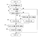
- the flowchart which shows an example of the flow of control for preventing an EGR rate from exceeding a misfire limit EGR rate.
- FIG. 1 is a system diagram showing an overall configuration of an internal combustion engine 1 to which the present invention is applied.
- the internal combustion engine 1 is mounted on a vehicle such as an automobile as a drive source, and an intake passage 2 and an exhaust passage 3 are connected to each other.
- a throttle valve 5 is provided in the intake passage 2 connected to the internal combustion engine 1 via the intake manifold 4, and an air flow meter 7 for detecting the intake air amount is provided upstream thereof.
- An exhaust catalyst 9 such as a three-way catalyst is provided for exhaust purification in the exhaust passage 3 connected to the internal combustion engine 1 via the exhaust manifold 8.
- the internal combustion engine 1 has a turbocharger 10 that is coaxially provided with a compressor 11 disposed in the intake passage 2 and a turbine 12 disposed in the exhaust passage 3.
- the compressor 11 is located upstream of the throttle valve 5 and is located downstream of the air flow meter 7.
- the turbine 12 is located on the upstream side of the exhaust catalyst 9.
- 13 in FIG. 1 is an intercooler provided on the downstream side of the throttle valve 5.
- a recirculation passage 14 that bypasses the compressor 11 and connects the upstream side and the downstream side of the compressor is connected to the intake passage 2.
- the recirculation passage 14 is provided with a recirculation valve 15 that controls the intake flow rate in the recirculation passage 14.
- the exhaust passage 3 is connected to an exhaust bypass passage 16 that bypasses the turbine 12 and connects the upstream side and the downstream side of the turbine 12.
- the exhaust bypass passage 16 is provided with a waste gate valve 17 that controls the exhaust flow rate in the exhaust bypass passage 16.
- the internal combustion engine 1 can perform exhaust gas recirculation (EGR), and an EGR passage 20 is provided between the exhaust passage 3 and the intake passage 2.
- EGR passage 20 One end of the EGR passage 20 is connected to the exhaust passage 3 at a position downstream of the exhaust catalyst 9, and the other end is connected to the intake passage 2 at a position downstream of the air flow meter 7 and upstream of the compressor 11. Yes.
- the EGR passage 20 is provided with an EGR control valve 21 and an EGR cooler 22.
- the valve opening degree of the EGR control valve 21 is controlled by the control unit 25 so that a predetermined EGR rate corresponding to the operating condition is obtained.
- control unit 25 includes a crank angle sensor 26 that detects the crank angle of a crankshaft (not shown), and an accelerator opening that detects the amount of depression of an accelerator pedal (not shown). Detection signals of sensors such as the degree sensor 27 and the EGR control valve opening sensor 28 for detecting the valve opening of the EGR control valve 21 are input.
- the control unit 25 controls the intake air amount, ignition timing, air-fuel ratio, etc. of the internal combustion engine 1 and controls the valve opening of the EGR control valve 21 as described above.
- exhaust gas recirculation control EGR control
- the valve openings of the throttle valve 5, the recirculation valve 15, and the waste gate valve 17 are also controlled by the control unit 25.
- the recirculation valve 15 is not controlled to be opened and closed by the control unit 25, and a so-called check valve that opens only when the pressure on the downstream side of the compressor 11 exceeds a predetermined pressure can be used. is there.
- a part of the exhaust gas is recirculated as EGR gas from the downstream side of the turbine 12 to the upstream side of the compressor 11, and basically the EGR control valve 21 in a steady state.
- the EGR rate is determined by the valve opening (opening rate).
- the EGR control valve 21 when the intake air amount becomes larger than the predetermined amount Qlim1, the EGR control valve 21 only opens the EGR regardless of the intake air amount.
- the exhaust gas EGR gas
- the exhaust gas hardly circulates regardless of the valve opening degree of the EGR control valve 21, and the EGR rate becomes substantially zero.
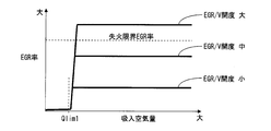
- FIG. 2 schematically shows the correlation between the intake air amount and the EGR rate when the valve opening degree of the EGR control valve 21 is set to three different valve opening degrees (large, medium, and small).
- the EGR rate at the relatively largest valve opening among the three valve openings in FIG. 2 is a predetermined value at which the internal combustion engine 1 misfires when the intake air amount becomes larger than the predetermined amount Qlim1. It exceeds the misfire limit EGR rate.
- the EGR rate at the intermediate valve opening and the EGR rate at the relatively smallest valve opening are such that the intake air amount is greater than the predetermined amount Qlim1. Even if it becomes larger, it is smaller than the misfire limit EGR rate in the steady state.
- the EGR control valve 21 if the EGR rate when the intake air amount becomes larger than the predetermined amount Qlim1 with the fixed valve opening is equal to or greater than the misfire limit EGR rate, the intake air even in the steady state If the amount exceeds the predetermined amount Qlim1, the internal combustion engine 1 will misfire.
- the EGR control valve 21 when the EGR control valve 21 is fixed, the amount of exhaust gas recirculated to the intake passage 2 (EGR amount) is reduced by limiting the intake air amount, and the EGR rate of the internal combustion engine 1 is reduced. Is controlled so as not to exceed the misfire limit EGR rate even during deceleration.
- the upper limit of the intake air amount is set to the predetermined amount Qlim1.
- the intake air amount limit value Qlim is set to the predetermined amount Qlim1.
- the upper limit of the intake air amount is a predetermined amount Qlim2 (details will be described later) as a second predetermined amount.
- the limit value Qlim of the intake air amount is set to the predetermined amount Qlim2.
- valve opening threshold EGRVOth corresponds to a valve opening at which the EGR rate becomes the misfire limit EGR rate in a steady state when the intake air amount is larger than the predetermined amount Qlim1.
- the predetermined amount Qlim1 is set to a value that is slightly smaller than the intake air amount at which the EGR rate starts to rise sharply. This is to prevent the EGR rate from exceeding the misfire limit EGR rate even if the intake air amount exceeds the predetermined amount Qlim1 due to a slight fluctuation in a steady state.
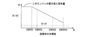
- the predetermined amount Qlim2 is larger than the predetermined amount Qlim1, and is set to be smaller as the valve opening when the EGR control valve 21 is fixed is larger.
- This predetermined amount Qlim2 is calculated from a predetermined amount Qlim2 calculation table as shown in FIG. 3, for example, using the valve opening when the EGR control valve 21 is fixed.
- the EGR rate temporarily increases during deceleration, so the EGR rate during deceleration is Although the misfire limit EGR rate may become larger, the temporary increase amount of the EGR rate at the time of deceleration has a correlation with the change of the intake air amount, and becomes larger as the change of the intake air amount at the time of deceleration becomes larger. Tend to be.
- the predetermined amount Qlim2 in the present embodiment is set so that the larger the valve opening when the EGR control valve 21 is fixed, the smaller the valve opening when the EGR control valve 21 is fixed in consideration of a temporary increase in the EGR rate during the deceleration transition. Yes. That is, if the valve opening degree to which the EGR control valve 21 is fixed is a valve opening degree that is less than the misfire limit EGR rate in a steady state, the intake air is in accordance with the valve opening degree to which the EGR control valve 21 is fixed. Relax the amount limit.
- the predetermined amount Qlim2 is set to the maximum intake air amount of the internal combustion engine 1 when the valve opening to which the EGR control valve 21 is fixed is equal to or smaller than the first valve opening EGRVO1, which is a predetermined minute opening. . That is, if the valve opening when the EGR control valve 21 is fixed is a very small opening, the intake air amount is not substantially limited.
- the predetermined amount Qlim2 is smaller than the maximum intake air amount of the internal combustion engine 1. And it is set to become smaller as the fixed valve opening becomes larger. That is, when the valve opening when the EGR control valve 21 is fixed is larger than the first valve opening EGRVO1 and not more than the valve opening threshold EGRVOth, the intake air amount is limited.
- the predetermined amount Qlim1 and the predetermined amount Qlim2 are set on the premise of different situations as described above. Therefore, the valve opening to which the EGR control valve 21 is fixed is equal to the valve opening threshold value EGRVOth. Sometimes discontinuous.
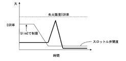
- 4 and 5 are characteristic diagrams schematically showing changes in the EGR rate during deceleration when the limit value Qlim of the intake air amount is set to the predetermined amount Qlim2.
- FIG. 4 shows a case where the valve opening degree to which the EGR control valve 21 is fixed is the second valve opening degree EGRVO2 slightly larger than the first valve opening degree EGRVO1.
- the valve opening to which the EGR control valve 21 is fixed is the second valve opening EGRVO2
- the amount of intake air before deceleration is not so limited, and the amount of intake air before and after deceleration changes. Since it is large, the temporary increase amount of the EGR rate at the time of deceleration also increases, but since the original EGR rate is small, the misfire limit EGR rate is not exceeded.
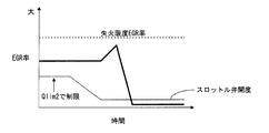
- FIG. 5 shows a case where the valve opening degree to which the EGR control valve 21 is fixed is the third valve opening degree EGRVO3 closer to the valve opening degree threshold value EGRVOth than the first valve opening degree EGRVO1.
- the valve opening degree to which the EGR control valve 21 is fixed is the third valve opening degree EGRVO3
- the intake air amount (throttle valve opening) before deceleration is limited by the predetermined amount Qlim2, and the intake air before and after deceleration. Since the amount change is small, the temporary increase amount of the EGR rate at the time of deceleration is also small, and the misfire limit EGR rate is not exceeded.
- the EGR control valve 21 when the EGR control valve 21 is fixed, by limiting the intake air amount so that the internal combustion engine 1 does not misfire even during deceleration, misfire of the internal combustion engine 1 is prevented, and In addition, it is possible to prevent the internal combustion engine 1 from starting. Further, even if the EGR control valve 21 is fixed, the internal combustion engine 1 can be operated. Therefore, a vehicle using the internal combustion engine 1 as a drive source is safe to a maintenance shop or the like to repair the EGR control valve 21. Can self-propelled.
- the predetermined amount Qlim1 and the predetermined amount Qlim2 used for the intake air amount limit value Qlim are selectively used, so that the valve opening degree to which the EGR control valve 21 is fixed is obtained. If the valve opening is such that it becomes less than the misfire limit EGR rate in a steady state, the output of the internal combustion engine when the EGR control valve 21 is secured while preventing the misfire of the internal combustion engine due to the EGR control valve 21 being secured. Can be improved relatively. Therefore, the smaller the opening degree to which the EGR control valve 21 is fixed, the quicker it can go to a maintenance shop or the like in order to repair the fixing of the EGR control valve 21.
- the EGR control valve 21 When the EGR control valve 21 is fixed, for example, if a warning lamp or the like is turned on to notify the driver, it can be repaired at a maintenance shop or the like as soon as possible.
- FIG. 6 is a flowchart showing an example of a control flow for preventing the EGR rate from exceeding the misfire limit EGR rate even if the EGR control valve 21 is fixed.
- the control routine shown in FIG. 6 is executed in the control unit 25 every predetermined time, for example, during the operation of the internal combustion engine 1.
- the engine speed Ne of the internal combustion engine 1 and the valve opening EGRVO of the EGR control valve 21 are read.
- the engine speed Ne is calculated based on the output signal of the crank angle sensor 26 described above.
- the valve opening EGRVO is the valve opening of the EGR control valve 21 detected by the above-described EGR control valve opening sensor 28.
- S2 it is determined whether or not the EGR control valve 21 is fixed. For example, when the detected valve opening degree EGRVO deviates from the target EGR control valve opening degree and the detected valve opening degree EGRVO is unchanged for a predetermined time, the EGR control valve 21 is fixed. Is determined to be fixed. If it is determined that the EGR control valve 21 is fixed, the process proceeds to S3. If it is not fixed, the current routine is terminated.
- the limit value Qlim of the intake air amount is set to the predetermined amount Qlim1.
- the upper limit value of the intake air amount becomes the predetermined amount Qlim1.
- the predetermined amount Qlim2 is calculated based on the detected valve opening EGRVO of the EGR control valve 21.
- the predetermined amount Qlim2 is a value set so as to decrease as the valve opening degree to which the EGR control valve 21 is fixed increases.
- the predetermined amount Qlim2 is calculated as shown in FIG. It is calculated by storing the table in the control unit 25. Then, the process proceeds to S6, where the intake air amount limit value Qlim is set to the predetermined amount Qlim2.
- the target throttle valve opening tTVO set based on the depression amount of the accelerator pedal is compared with the throttle valve opening limit value TVOlim calculated in S7, and the target throttle valve opening tTVO is determined as the throttle valve opening.
- the target throttle valve opening degree tTVO is limited by the throttle valve opening degree limit value TVOlim.
- the throttle valve 5 is controlled using the throttle valve opening limit value TVOlim as the target throttle opening.
Landscapes
- Engineering & Computer Science (AREA)
- Chemical & Material Sciences (AREA)
- Combustion & Propulsion (AREA)
- Mechanical Engineering (AREA)
- General Engineering & Computer Science (AREA)
- Electrical Control Of Air Or Fuel Supplied To Internal-Combustion Engine (AREA)
- Exhaust-Gas Circulating Devices (AREA)
- Combined Controls Of Internal Combustion Engines (AREA)
- Output Control And Ontrol Of Special Type Engine (AREA)
Abstract
Description
Claims (6)
- スロットル弁の上流側に位置する過給機と、上記過給機の上流側に排気の一部を還流するEGR通路と、上記EGR通路の途中に配置されたEGR制御弁と、上記EGR制御弁の弁開度を検出可能なEGR制御弁開度検出手段と、を有し、吸入空気量が所定量より大きくなると、上記EGR制御弁の弁開度に応じた量の排気が還流し、吸入空気量が上記所定量以下になると、上記EGR制御弁の弁開度に関わらず排気がほとんど還流しない内燃機関の排気還流装置において、
上記EGR制御弁の固着の有無を判定するEGR制御弁固着判定手段と、
上記EGR制御弁が固着した際には、内燃機関が失火しないように吸入空気量に制限を加える吸入空気量制限手段と、を有する内燃機関の排気還流制御装置。 - 内燃機関が失火する所定の失火限界EGR率より大きくなるような弁開度で上記EGR制御弁が固着した場合には、吸入空気量が上記所定量に制限される請求項1に記載の内燃機関の排気還流制御装置。
- 内燃機関が失火する所定の失火限界EGR率以下となるような弁開度で上記EGR制御弁が固着した場合には、吸入空気量が上記所定量より大きい第2所定量に制限される請求項1または2に記載の内燃機関の排気還流制御装置。
- 上記第2所定量は、上記EGR制御弁の固着した弁開度が大きいほど小さくなるよう設定されている請求項3に記載の内燃機関の排気還流制御装置。
- 上記第2所定量は、上記EGR制御弁の固着した弁開度が微小開度であれば、当該内燃機関の最大吸入空気量に設定される請求項3または4に記載の内燃機関の排気還流制御装置。
- 吸入空気量が所定量より大きくなるとEGR通路の途中に配置されたEGR制御弁の弁開度に応じた量の排気が過給機の上流側に還流し、吸入空気量が上記所定量以下になると上記EGR制御弁の弁開度に関わらず排気がほとんど上記過給機の上流側に還流しない内燃機関において、
上記EGR制御弁が固着した際には、当該内燃機関が失火しないように、吸入空気量を制限することで過給機の上流側に還流される排気還流量を制御する内燃機関の排気還流制御方法。
Priority Applications (7)
| Application Number | Priority Date | Filing Date | Title |
|---|---|---|---|
| JP2014559525A JP5773094B2 (ja) | 2013-02-01 | 2013-12-24 | 内燃機関の排気還流制御装置及び排気還流制御方法 |
| MX2015009413A MX341045B (es) | 2013-02-01 | 2013-12-24 | Dispositivo de control de recirculacion de gas de escape y metodo de control de recirculacion de gas de escape para motor de combustion interna. |
| US14/763,933 US9574526B2 (en) | 2013-02-01 | 2013-12-24 | Exhaust gas recirculation control device and exhaust gas recirculation control method for internal combustion engine |
| CN201380071232.XA CN104956062B (zh) | 2013-02-01 | 2013-12-24 | 内燃机的排气回流控制装置及排气回流控制方法 |
| BR112015017409-4A BR112015017409B1 (pt) | 2013-02-01 | 2013-12-24 | Dispositivo de controle de recirculação do gás de exaustão e método de recirculação do gás de exaustão para o motor de combustão interna |
| RU2015136929/06A RU2599685C1 (ru) | 2013-02-01 | 2013-12-24 | Устройство управления рециркуляцией отработавшего газа и способ управления рециркуляцией отработавшего газа для двигателя внутреннего сгорания |
| EP13874107.9A EP2952729B1 (en) | 2013-02-01 | 2013-12-24 | Exhaust gas recirculation control device and exhaust gas recirculation control method for an internal combustion engine |
Applications Claiming Priority (2)
| Application Number | Priority Date | Filing Date | Title |
|---|---|---|---|
| JP2013-017986 | 2013-02-01 | ||
| JP2013017986 | 2013-02-01 |
Publications (1)
| Publication Number | Publication Date |
|---|---|
| WO2014119182A1 true WO2014119182A1 (ja) | 2014-08-07 |
Family
ID=51261906
Family Applications (1)
| Application Number | Title | Priority Date | Filing Date |
|---|---|---|---|
| PCT/JP2013/084414 Ceased WO2014119182A1 (ja) | 2013-02-01 | 2013-12-24 | 内燃機関の排気還流制御装置及び排気還流制御方法 |
Country Status (9)
| Country | Link |
|---|---|
| US (1) | US9574526B2 (ja) |
| EP (1) | EP2952729B1 (ja) |
| JP (1) | JP5773094B2 (ja) |
| CN (1) | CN104956062B (ja) |
| BR (1) | BR112015017409B1 (ja) |
| MX (1) | MX341045B (ja) |
| MY (1) | MY155740A (ja) |
| RU (1) | RU2599685C1 (ja) |
| WO (1) | WO2014119182A1 (ja) |
Cited By (3)
| Publication number | Priority date | Publication date | Assignee | Title |
|---|---|---|---|---|
| US20180030934A1 (en) * | 2016-07-26 | 2018-02-01 | Hyundai Motor Company | Engine system |
| EP3348818A4 (en) * | 2015-09-07 | 2018-09-12 | Nissan Motor Co., Ltd. | Exhaust gas recirculation control method and exhaust gas recirculation control device |
| JP2020063723A (ja) * | 2018-10-19 | 2020-04-23 | トヨタ自動車株式会社 | エンジン制御装置 |
Families Citing this family (8)
| Publication number | Priority date | Publication date | Assignee | Title |
|---|---|---|---|---|
| US9926839B2 (en) | 2014-05-30 | 2018-03-27 | Nissan Motor Co., Ltd. | Internal combustion engine and method for controlling internal combustion engine |
| EP3153684B1 (en) * | 2014-06-06 | 2020-03-04 | Yanmar Co., Ltd. | Engine device |
| KR101912513B1 (ko) * | 2014-06-06 | 2018-10-26 | 얀마 가부시키가이샤 | 엔진 장치 |
| KR20170128785A (ko) * | 2016-05-13 | 2017-11-24 | 현대자동차주식회사 | 차량의 egr밸브 제어방법 및 그 제어시스템 |
| JP6561967B2 (ja) * | 2016-11-04 | 2019-08-21 | トヨタ自動車株式会社 | 内燃機関の制御装置 |
| DE102017115349B4 (de) * | 2017-07-10 | 2019-01-24 | Dr. Ing. H.C. F. Porsche Aktiengesellschaft | Abgasturboladersystem für eine mehrreihige Brennkraftmaschine und Verfahren zum Betreiben eines Abgasturboladersystems |
| JP6486523B1 (ja) * | 2018-03-13 | 2019-03-20 | 愛三工業株式会社 | エンジンシステム |
| JP6486536B1 (ja) * | 2018-03-13 | 2019-03-20 | 愛三工業株式会社 | ガソリンエンジンシステム |
Citations (3)
| Publication number | Priority date | Publication date | Assignee | Title |
|---|---|---|---|---|
| JPH0925852A (ja) | 1995-07-10 | 1997-01-28 | Nissan Motor Co Ltd | エンジンのフェイルセーフ装置 |
| JP2005207285A (ja) * | 2004-01-21 | 2005-08-04 | Toyota Motor Corp | 内燃機関制御装置 |
| JP2010255602A (ja) * | 2009-04-28 | 2010-11-11 | Toyota Motor Corp | 車両の制御装置 |
Family Cites Families (13)
| Publication number | Priority date | Publication date | Assignee | Title |
|---|---|---|---|---|
| JP4013290B2 (ja) | 1997-07-17 | 2007-11-28 | マツダ株式会社 | ターボ過給機付直噴式エンジンの排気還流制御装置 |
| JP4367335B2 (ja) * | 2004-12-27 | 2009-11-18 | 日産自動車株式会社 | エンジンの制御装置。 |
| JP4502038B2 (ja) * | 2008-04-14 | 2010-07-14 | トヨタ自動車株式会社 | 内燃機関の制御システム |
| JP2009264149A (ja) * | 2008-04-23 | 2009-11-12 | Toyota Motor Corp | 内燃機関の制御装置 |
| JP5393506B2 (ja) * | 2010-01-27 | 2014-01-22 | 三菱重工業株式会社 | エンジンの吸気系に用いられる制御弁の制御装置及び制御方法 |
| JP5143170B2 (ja) * | 2010-03-17 | 2013-02-13 | 日立オートモティブシステムズ株式会社 | 内燃機関の制御方法 |
| RU2465484C2 (ru) * | 2010-03-19 | 2012-10-27 | Федеральное государственное унитарное предприятие "Центральный ордена Трудового Красного Знамени научно-исследовательский автомобильный и автомоторный институт "НАМИ" | Способ питания поршневого двигателя и система питания этого двигателя |
| US8418463B2 (en) * | 2010-04-15 | 2013-04-16 | Ford Global Technologies, Llc | Condensate management for motor-vehicle compressed air storage systems |
| JP5277351B2 (ja) * | 2010-06-22 | 2013-08-28 | 本田技研工業株式会社 | 内燃機関の制御装置 |
| US9181904B2 (en) * | 2010-08-10 | 2015-11-10 | Ford Global Technologies, Llc | Method and system for exhaust gas recirculation control |
| US8103428B2 (en) * | 2011-01-11 | 2012-01-24 | Ford Global Technologies, Llc | Method for controlling an engine |
| RU112280U1 (ru) * | 2011-05-24 | 2012-01-10 | Государственное образовательное учреждение высшего профессионального образования "Челябинский государственный педагогический университет ГОУ ВПО "ЧГПУ" (ППИ) | Система управления работой транспортного дизеля с газотурбинным наддувом |
| US9027343B2 (en) * | 2012-06-14 | 2015-05-12 | Ford Global Technologies, Llc | Approach for supplying vacuum via a supercharger |
-
2013
- 2013-12-24 EP EP13874107.9A patent/EP2952729B1/en active Active
- 2013-12-24 BR BR112015017409-4A patent/BR112015017409B1/pt active IP Right Grant
- 2013-12-24 MX MX2015009413A patent/MX341045B/es active IP Right Grant
- 2013-12-24 WO PCT/JP2013/084414 patent/WO2014119182A1/ja not_active Ceased
- 2013-12-24 US US14/763,933 patent/US9574526B2/en active Active
- 2013-12-24 RU RU2015136929/06A patent/RU2599685C1/ru active
- 2013-12-24 CN CN201380071232.XA patent/CN104956062B/zh active Active
- 2013-12-24 JP JP2014559525A patent/JP5773094B2/ja active Active
- 2013-12-24 MY MYPI2015702138A patent/MY155740A/en unknown
Patent Citations (3)
| Publication number | Priority date | Publication date | Assignee | Title |
|---|---|---|---|---|
| JPH0925852A (ja) | 1995-07-10 | 1997-01-28 | Nissan Motor Co Ltd | エンジンのフェイルセーフ装置 |
| JP2005207285A (ja) * | 2004-01-21 | 2005-08-04 | Toyota Motor Corp | 内燃機関制御装置 |
| JP2010255602A (ja) * | 2009-04-28 | 2010-11-11 | Toyota Motor Corp | 車両の制御装置 |
Non-Patent Citations (1)
| Title |
|---|
| See also references of EP2952729A4 |
Cited By (5)
| Publication number | Priority date | Publication date | Assignee | Title |
|---|---|---|---|---|
| EP3348818A4 (en) * | 2015-09-07 | 2018-09-12 | Nissan Motor Co., Ltd. | Exhaust gas recirculation control method and exhaust gas recirculation control device |
| US20180030934A1 (en) * | 2016-07-26 | 2018-02-01 | Hyundai Motor Company | Engine system |
| US10273908B2 (en) * | 2016-07-26 | 2019-04-30 | Hyundai Motor Company | Engine system |
| JP2020063723A (ja) * | 2018-10-19 | 2020-04-23 | トヨタ自動車株式会社 | エンジン制御装置 |
| JP7271901B2 (ja) | 2018-10-19 | 2023-05-12 | トヨタ自動車株式会社 | エンジン制御装置 |
Also Published As
| Publication number | Publication date |
|---|---|
| MY155740A (en) | 2015-11-18 |
| RU2599685C1 (ru) | 2016-10-10 |
| MX2015009413A (es) | 2015-09-24 |
| EP2952729B1 (en) | 2017-09-06 |
| MX341045B (es) | 2016-08-05 |
| EP2952729A4 (en) | 2016-06-15 |
| BR112015017409B1 (pt) | 2021-07-13 |
| EP2952729A1 (en) | 2015-12-09 |
| BR112015017409A2 (pt) | 2020-10-20 |
| CN104956062A (zh) | 2015-09-30 |
| US9574526B2 (en) | 2017-02-21 |
| JP5773094B2 (ja) | 2015-09-02 |
| JPWO2014119182A1 (ja) | 2017-01-26 |
| CN104956062B (zh) | 2017-03-08 |
| US20150361872A1 (en) | 2015-12-17 |
Similar Documents
| Publication | Publication Date | Title |
|---|---|---|
| JP5773094B2 (ja) | 内燃機関の排気還流制御装置及び排気還流制御方法 | |
| JP5673896B2 (ja) | 内燃機関の制御装置 | |
| EP2876291B1 (en) | Internal combustion engine | |
| JP5707967B2 (ja) | 内燃機関の過給圧診断装置 | |
| JP6237512B2 (ja) | 過給機の異常診断装置 | |
| CN108463620B (zh) | 废气旁通阀的控制方法及控制装置 | |
| US9624824B2 (en) | Control device and control method for internal combustion engine | |
| US10436158B2 (en) | Abnormality detection device for humidity sensor | |
| JP6743914B2 (ja) | 内燃機関の制御方法及び内燃機関の制御装置 | |
| JP2017172434A (ja) | エンジンの失火判定装置 | |
| JP5282695B2 (ja) | 過給機付き内燃機関の制御装置 | |
| JP2010151038A (ja) | 内燃機関の制御装置 | |
| JP2008190435A (ja) | インタークーラの異常検出装置 | |
| KR102006582B1 (ko) | 내연 기관의 제어 장치 및 내연 기관의 제어 방법 | |
| JP2014227844A (ja) | 内燃機関の制御装置 | |
| JP2014009590A (ja) | 過給システム付き内燃機関の制御装置 | |
| WO2013190933A1 (ja) | 内燃機関の排気還流装置及び排気還流装置のegr算出方法 | |
| WO2013187141A1 (ja) | 内燃機関の制御装置及び制御方法 | |
| US20170363025A1 (en) | Control apparatus for internal combustion engine | |
| US10738720B2 (en) | Method for controlling an air boosting apparatus in a two-stroke, opposed piston engine, and a two-stroke, opposed piston engine with an air boosting apparatus | |
| WO2025088747A1 (ja) | 内燃機関の排気還流装置のフェールセーフ方法および装置 | |
| US20200088082A1 (en) | Exhaust system and method of operating the same | |
| JP2015218689A (ja) | ターボ過給機付エンジンの制御装置 | |
| WO2015189012A1 (en) | Exhaust gas recirculation testing method |
Legal Events
| Date | Code | Title | Description |
|---|---|---|---|
| 121 | Ep: the epo has been informed by wipo that ep was designated in this application |
Ref document number: 13874107 Country of ref document: EP Kind code of ref document: A1 |
|
| ENP | Entry into the national phase |
Ref document number: 2014559525 Country of ref document: JP Kind code of ref document: A |
|
| WWE | Wipo information: entry into national phase |
Ref document number: MX/A/2015/009413 Country of ref document: MX |
|
| WWE | Wipo information: entry into national phase |
Ref document number: IDP00201504610 Country of ref document: ID |
|
| WWE | Wipo information: entry into national phase |
Ref document number: 14763933 Country of ref document: US |
|
| NENP | Non-entry into the national phase |
Ref country code: DE |
|
| REG | Reference to national code |
Ref country code: BR Ref legal event code: B01A Ref document number: 112015017409 Country of ref document: BR |
|
| ENP | Entry into the national phase |
Ref document number: 2015136929 Country of ref document: RU Kind code of ref document: A |
|
| REEP | Request for entry into the european phase |
Ref document number: 2013874107 Country of ref document: EP |
|
| WWE | Wipo information: entry into national phase |
Ref document number: 2013874107 Country of ref document: EP |
|
| ENP | Entry into the national phase |
Ref document number: 112015017409 Country of ref document: BR Kind code of ref document: A2 Effective date: 20150721 |
|
| ENPC | Correction to former announcement of entry into national phase, pct application did not enter into the national phase |
Ref country code: BR Free format text: ANULADA A PUBLICACAO CODIGO 1.3 NA RPI NO 2427 DE 11/07/2017 POR TER SIDO INDEVIDA. |
|
| REG | Reference to national code |
Ref country code: BR Ref legal event code: B01E Ref document number: 112015017409 Country of ref document: BR Kind code of ref document: A2 Free format text: APRESENTE AS TRADUCAO SIMPLES DA FOLHA DE ROSTO DA CERTIDAO DE DEPOSITO DA PRIORIDADE JP 2013-017986; OU DECLARACAO DE QUE OS DADOS DO PEDIDO INTERNACIONAL ESTAO FIELMENTE CONTIDOS NAS PRIORIDADE REIVINDICADA, CONTENDO TODOS OS DADOS IDENTIFICADORES DESTAS (TITULARES, NUMERO DEREGISTRO, DATA E TITULO), CONFORME O PARAGRAFO UNICO DO ART. 25 DA RESOLUCAO 77/2013. CABE SALIENTAR QUE NAO FOI POSSIVEL IDENTIFICAR OS TITULARES DOS PEDIDOS NOS DOCUMENTOS JUNTADOS AO PROCESSO, TAMPOUCO NOS APRESENTADOS NA OMPI, POIS SE ENCONTRAM EM JAPONES. |
|
| ENP | Entry into the national phase |
Ref document number: 112015017409 Country of ref document: BR Kind code of ref document: A2 Effective date: 20150721 |