WO2014119210A1 - Outil électrique - Google Patents
Outil électrique Download PDFInfo
- Publication number
- WO2014119210A1 WO2014119210A1 PCT/JP2013/084841 JP2013084841W WO2014119210A1 WO 2014119210 A1 WO2014119210 A1 WO 2014119210A1 JP 2013084841 W JP2013084841 W JP 2013084841W WO 2014119210 A1 WO2014119210 A1 WO 2014119210A1
- Authority
- WO
- WIPO (PCT)
- Prior art keywords
- battery mounting
- battery
- motor shaft
- electric
- housing
- Prior art date
- Legal status (The legal status is an assumption and is not a legal conclusion. Google has not performed a legal analysis and makes no representation as to the accuracy of the status listed.)
- Ceased
Links
Images








Classifications
-
- B—PERFORMING OPERATIONS; TRANSPORTING
- B25—HAND TOOLS; PORTABLE POWER-DRIVEN TOOLS; MANIPULATORS
- B25F—COMBINATION OR MULTI-PURPOSE TOOLS NOT OTHERWISE PROVIDED FOR; DETAILS OR COMPONENTS OF PORTABLE POWER-DRIVEN TOOLS NOT PARTICULARLY RELATED TO THE OPERATIONS PERFORMED AND NOT OTHERWISE PROVIDED FOR
- B25F5/00—Details or components of portable power-driven tools not particularly related to the operations performed and not otherwise provided for
- B25F5/02—Construction of casings, bodies or handles
-
- B—PERFORMING OPERATIONS; TRANSPORTING
- B24—GRINDING; POLISHING
- B24B—MACHINES, DEVICES, OR PROCESSES FOR GRINDING OR POLISHING; DRESSING OR CONDITIONING OF ABRADING SURFACES; FEEDING OF GRINDING, POLISHING, OR LAPPING AGENTS
- B24B23/00—Portable grinding machines, e.g. hand-guided; Accessories therefor
- B24B23/02—Portable grinding machines, e.g. hand-guided; Accessories therefor with rotating grinding tools; Accessories therefor
- B24B23/028—Angle tools
Definitions
- the present invention relates to a hand-held power tool for holding a hand to perform a machining operation represented by a disc grinder.
- a disc grinder has been known as a hand-held power tool (for example, JP 2012-213820 A).
- This disc grinder is equipped with an electric motor as a drive source in a tool body.
- a grip portion that is gripped by the operator is formed in the exterior housing.
- a gear head is assembled to the front portion of the tool body.
- the gear head includes a bevel gear (bevel gear) and the like.
- the spindle of this bevel gear is configured as an output spindle.
- the output axis of the output spindle (the rotation axis of the grindstone) is orthogonal to the axis of the motor drive shaft of the electric motor.
- a circular grindstone as a tip tool is attached to the output spindle protruding from the gear head of the bevel gear.
- a cover for preventing dust scattering such as grinding powder is provided.
- a rechargeable battery generally called a battery pack is mounted as a power supply. This rechargeable battery is charged by a dedicated charger and attached to the tool body. In such a disc grinder, a rechargeable battery is generally attached to the rearmost part of the tool body.
- the present invention has been made in view of such circumstances, and the problem to be solved by the present invention is that a hand-held power tool for carrying out a processing operation by hand is handled as a power tool. It is to respond to a request to set a high voltage or set a large supply capacity when using it as an electric power tool while suppressing the deterioration of the goodness.
- An electric tool according to a first aspect of the present invention includes a battery mounting portion on which a rechargeable battery is slid and mounted, an electric motor that rotationally drives a motor shaft with electric power supplied from the rechargeable battery, and the motor
- An electric power tool having a tip tool holding portion driven by a shaft, wherein the battery mounting portions are arranged one by one at positions symmetrical with respect to the axis of the motor shaft with respect to a housing forming an exterior. Two are provided.
- the two battery mounting portions are provided, two rechargeable batteries can be mounted. Accordingly, it is possible to respond to a request for setting a high voltage or a large supply capacity when used as a power tool.
- the two battery mounting portions are arranged one by one at positions symmetrical with respect to the axis of the motor shaft with respect to the housing forming the exterior, so that the rechargeable type It is possible to balance the weight that is increased by mounting the battery. As a result, it is possible to suppress the loss of good handling performance as an electric tool when the processing operation is performed by hand.
- An electric tool includes a battery mounting portion on which a rechargeable battery is slid and mounted, an electric motor that rotationally drives a motor shaft with electric power supplied from the rechargeable battery, and the motor An electric power tool having a tip tool holding portion driven by a shaft, wherein the battery mounting portion is provided with respect to a motor housing that supports the electric motor.
- An electric power tool includes a battery mounting portion on which a rechargeable battery is slid and mounted, an electric motor that rotates a motor shaft by electric power supplied from the rechargeable battery, and the motor
- An electric power tool having a tip tool holding portion driven by a shaft, wherein the battery mounting portion is mounted on a housing forming an exterior so that the axes in a direction in which the rechargeable battery slides are parallel to each other. Two are provided.
- An electric tool includes a battery mounting portion on which a rechargeable battery is slid and mounted, an electric motor that rotationally drives a motor shaft with electric power supplied from the rechargeable battery, and the motor
- An electric power tool having a tip tool holding portion driven by a shaft, and a housing forming an exterior is provided with a handle portion formed by forming a loop shape, and the battery mounting portion is It is provided for a part of the loop shape.
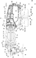
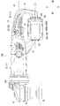
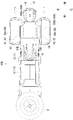
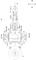
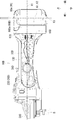
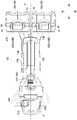
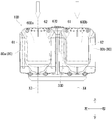
- FIG. 3 is a side view showing a substantially entire appearance by partially cutting a disc grinder. It is an internal structure figure which shows the halved internal structure of the disc grinder shown in FIG. It is the top view which looked at the disk grinder shown in FIG. 1 from the lower side. It is the top view which looked at the disc grinder shown in FIG. 1 from the rear side. It is a perspective view of the rechargeable battery slidably mounted on the battery mounting portion. It is a top view which expands and shows the battery terminal connection part used as the (VI) part of FIG.
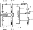
- FIG. 2 is a conceptual circuit diagram schematically showing a circuit structure of an electric motor. It is a side view which shows the whole external appearance of the disc grinder of 2nd Embodiment.
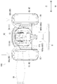
- FIG. 17 It is a side view which shows the whole external appearance of the disc grinder of 5th Embodiment. It is the top view which looked at the disc grinder shown in FIG. 17 from the upper side. It is the top view which looked at the disk grinder shown in FIG. 17 from the rear side.
- FIG. 1 is a disc grinder corresponding to the electric power tool according to the present invention.
- 2 shows a half-divided internal structure of the disc grinder 10 shown in FIG.
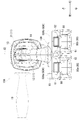
- the disc grinder shown in FIG. 1 is viewed from below.
- the disc grinder shown in FIG. 1 is viewed from the rear side.
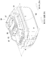
- the perspective view shown in FIG. 5 shows a rechargeable battery 80 that is slid and mounted on the battery mounting portion.
- the battery terminal connection part used as the (VI) part of FIG. 3 is expanded and shown.
- FIG. 7 the circuit structure of the electric motor is schematically shown.
- the disc grinder 10 will be described using the directions described in the drawings.
- This disc grinder 10 is a hand-held electric tool for a user to perform a machining operation by hand, and is a high power type disc grinder in which the voltage of supplied power is set to 36V.
- the disc grinder 10 is configured to be driven by sliding a rechargeable battery 80 as a power source.
- the disc grinder 10 is a so-called two-handle type disc grinder that is used by an operator with both hands at the site. That is, the disc grinder 10 has two handles, a handle portion 13 provided as a part of the grip housing 12, a head side grip 19 attached to the female screw portion 521 for attachment of the gear head 51 (head housing 52), and Have
- the grip housing 12 forms a housing by combining the left grip housing 12A and the right grip housing 12B which are divided into two.
- the disc grinder 10 generally includes a housing 11, an electric motor 32, and a gear mechanism 53.
- the housing 11 includes a grip housing 12 and a motor housing 31 in order from the rear side.
- the grip housing 12 and the motor housing 31 are connected to each other and form a part of the exterior of the disc grinder 10.
- a gear head 51 is attached to the front end of the grip housing 12 and the motor housing 31 thus connected via a gear housing cover 47.
- the grip housing 12 is formed as a resin-made halved molded part.
- the operation switch 20, the drive controller 17, the power controller 18, and the battery mounting portion 60 (60 a, 60 b) are sandwiched from the left and right by the half-molded parts forming the grip housing 12 and accommodated in the grip housing 12. Has been.
- the left and right half molded parts forming the grip housing 12 are fixed to each other by a screw boss 69.
- the grip housing 12 is formed in a loop shape as shown in the figure. That is, the grip housing 12 is provided with a handle portion 13 formed by forming this loop shape. Specifically, as shown in FIGS. 1 to 3, the grip housing 12 has a ring shape (loop shape) extending in the front-rear direction.
- the upper portion of the grip housing 12 is formed as a handle portion 13.
- An appropriate elastomer is attached to the outer peripheral surface of the handle portion 13. This elastomer ensures functions such as anti-slip when the handle portion 13 is gripped.
- a rear side connection portion 14 protruding downward is formed.
- a front side connection portion 15 protruding downward is also formed on the front side of the handle portion 13.
- the lower part of the rear connecting part 14 and the lower part of the front connecting part 15 are connected as a lower connecting part 16.
- the lower connecting portion 16 forms a lower portion of the grip housing 12 having a loop shape.
- the lower connecting portion 16 is formed in an arch shape.
- the lower connecting portion 16 is provided with two battery mounting portions 60 (60a, 60b) which will be described in detail later.
- a drive controller 17 is provided on the front portion of the grip housing 12.
- the drive controller 17 includes various electric material parts such as a shunt resistor and an FET (field-effect transistor) circuit (a part of the drive controller 17).
- the drive controller 17 is a board that is electrically connected to the brush of the electric motor 32 and performs the main control of the disc grinder 10.
- a power controller 18 is provided in the lower connecting portion 16.
- the power controller 18 is a board that controls the voltage of power supplied from the rechargeable battery 80 (80a, 80b) mounted on the battery mounting unit 60 (60a, 60b).
- the handle portion 13 is provided with an operation switch 20.
- the operation switch 20 includes a switch main body 21 and an operation button unit 22.
- the switch body 21 is built in the grip housing 12 and supported by the grip housing 12.
- the switch body 21 is composed of widely used contact switches.
- the operation button 22 is supported by the grip housing 12 so as to be movable in the vertical direction.
- the contact of the switch body 21 is turned on by a pressing operation along the direction in which the handle portion 13 of the operation button portion 22 is gripped.
- the switch body 21 inputs a signal indicating that the switch is turned on to the drive controller 17.
- the operation button portion 22 is not pushed, the push is released by an unillustrated urging spring, and the contact is turned off.
- a shift dial 23 is provided on the front side of the handle portion 13 and on the upper portion of the handle portion 13.
- the transmission dial 23 can set the rotational speed of the electric motor by turning the dial.
- the transmission dial 23 inputs a signal indicating the operated rotational speed to the drive controller 17.
- a rear bearing 41 that supports a motor shaft 33 of an electric motor 32 described below is provided at the front end portion of the grip housing 12. The rear bearing 41 is supported by the grip housing 12.
- a motor housing 31 is connected to the front side of the grip housing 12.
- the motor housing 31 is formed as a resin molded part.
- the motor housing 31 supports an electric motor 32 disposed inside the motor housing 31.
- the electric motor 32 rotationally drives the motor shaft 33 with supplied power.
- the electric motor 32 is a so-called brush motor and includes a stator 34, a rotor 35, and a commutator 36.
- the stator 34 is a permanent magnet supported by the motor housing 31.
- the rotor 35 is formed by winding a coil.
- a motor shaft 33 is set as the rotation shaft of the rotor 35.
- the motor shaft 33 is rotatably supported by a rear bearing 41 on the rear end side and a front bearing 42 on the front end side.
- a cooling fan 38 is attached to the front side of the rotor 35 in the motor shaft 33.
- the front bearing 42 is supported by the gear housing cover 47. Further, a pinion gear 45 having the motor shaft 33 as a rotation shaft is provided at the front end of the motor shaft 33.
- the pinion gear 45 has a shape as a tapered bevel gear that meshes with a bevel gear 54 of a gear mechanism 53 described below.
- An imaginary line indicated by a reference sign X ⁇ b> 1 indicates a rotation axis of the motor shaft 33.
- a gear head 51 is connected to the front side of the motor housing 31.
- the gear head 51 includes a head housing 52 and a gear mechanism 53.
- the head housing 52 is made of an aluminum casting.
- the head housing 52 is internally provided with a gear mechanism 53 that converts the drive mode of the rotational drive of the motor shaft 33.
- the gear mechanism 53 includes a bevel gear 54.
- the bevel gear 54 meshes with the pinion gear 45 attached to the front end of the motor shaft 33 described above.
- the bevel gear 54 is provided on an output shaft 55 that is a rotation shaft of the bevel gear 54.
- the output shaft 55 is rotatably supported by an upper bearing 57 and a lower bearing 58.
- the upper bearing 57 and the lower bearing 58 are supported by the head housing 52.
- the lower end of the output shaft 55 is configured as an attachment portion 56 that can attach a tip tool B such as a grindstone. That is, the attachment portion 56 corresponds to the tip tool holding portion according to the present invention.
- Numeral 59 is a gear stopper that restricts rotation around the output shaft.
- An imaginary line indicated by a reference sign X2 indicates the rotation axis of the output shaft 55.
- a mounting female screw portion 521 for mounting the head side grip 19 is provided on both the left and right side surfaces of the head housing 52.
- a male screw portion (not shown) provided on the head-side grip 19 can be screwed into the female screw portion 521 for attachment. As a result, the head-side grip 19 can be attached to the gear head 51.
- the two battery mounting portions 60 (60a, 60b) provided in the lower connecting portion 16 of the grip housing 12 will be described. That is, the lower connecting portion 16 of the grip housing 12 is provided with two battery mounting portions 60a and 60b. That is, the two battery mounting portions 60a and 60b are provided for a part of the loop shape of the grip housing 12 in which the handle portion 13 is provided. A part of the loop shape is set at the lower connecting portion 16 of the grip housing 12. Rechargeable batteries 80a and 80b that are mounted by sliding are attached to the battery mounting portions 60a and 60b, respectively.
- These rechargeable batteries 80a and 80b are rechargeable batteries 80 in which the voltage of widely used supply power is set to 18V, as shown in FIG.
- This rechargeable battery 80 is a so-called slide-type rechargeable battery that is mounted on the battery mounting portion 60 by sliding.
- a structure for sliding mounting and a structure for electrical connection are provided on the upper surface (connection terminal arrangement surface) side of the rechargeable battery 80 in the figure. That is, as shown in FIG. 5, a pair of slide guide portions 81 and 82 are provided on the upper surface side of the rechargeable battery 80 as a structure for sliding mounting.
- a positive electrode side terminal 83, a negative electrode side terminal 84, and a signal side terminal 85 are provided on the upper surface side of the rechargeable battery 80 as a structure to be electrically connected.
- the rechargeable battery 80 is slidably mounted on the upper surface side of the rechargeable battery 80 and is electrically connected, the rechargeable battery 80 is engaged with the battery mounting portion 60 in this state.
- a male hook 87 is provided to be in a state of being brought into the closed state.
- a push button 88 for operating the male hook 87 is provided on the side of the rechargeable battery 80 in the direction of removal (see FIG. 4 and the like).
- the push button 88 is connected to the male hook 87.
- the male hook 87 is operated and stored in the rechargeable battery 80.
- the rechargeable battery 80 is not engaged with the battery mounting portion 60, and the rechargeable battery 80 can be removed from the battery mounting portion 60.
- 5 indicates the length of the rechargeable battery 80 in the longitudinal direction.
- 5 indicates the width of the rechargeable battery 80 in the width direction.
- symbol H described in FIG. 5 has shown the length of the height direction of this rechargeable battery 80.
- the battery mounting portion 60 for sliding and mounting the above-described rechargeable battery 80 will be described.
- the battery mounting portion 60 has a structure in which the above-described rechargeable battery 80 is mounted by sliding. For this reason, it has a mounting structure corresponding to the rechargeable battery 80 described above. That is, as shown in FIGS. 3 and 6, the battery mounting portion 60 is provided with a structure for slidingly mounting the above-described rechargeable battery 80 and a structure for electrically connecting the above-described rechargeable battery 80. Yes.
- the battery mounting portion 60 is provided with a pair of slide guide receiving portions 61 and 62 as a structure for sliding mounting. As shown in FIG. 6, the battery mounting portion 60 is provided with a battery terminal connection portion 600 including a positive terminal 63, a negative terminal 64, and a signal terminal 65 as a structure for electrical connection. It has been. As shown in FIG. 3, when the rechargeable battery 80 is slid and electrically connected to the battery mounting portion 60, the rechargeable battery 80 in this state is locked to the battery mounting portion 60. The That is, the battery mounting portion 60 is provided with a female portion (dent) 66 that engages with the male hook 87 of the rechargeable battery 80 in this state.
- an imaginary line indicated by reference numeral X3 in FIG. 3 indicates an axis on which the rechargeable battery 80a is slid and mounted on the first battery mounting portion 60a.
- symbol X4 of FIG. 3 has shown the axis line by which the rechargeable battery 80b is slid with respect to the 2nd battery mounting part 60b.
- the first and second battery mounting portions 60 a and 60 b are configured by the structure of the battery mounting portion 60 described above.
- the axis line X3 and the axis line X4 are set to be parallel to each other. That is, the battery mounting portions 60a and 60b of the first embodiment are provided with respect to the lower connecting portion 16 of the grip housing 12 so that the two rechargeable batteries 80a and 80b can be mounted by sliding in parallel. ing.
- the first battery mounting portion 60a and the second battery mounting portion 60b are provided in a parallel arrangement relationship that is shifted back and forth with respect to the lower connecting portion 16.
- the slide mounting directions of the rechargeable batteries 80a and 80b with respect to the first and second battery mounting portions 60a and 60b are both set to be mounted by sliding from the right to the left. That is, the slide mounting of the rechargeable batteries 80a and 80b with respect to the first and second battery mounting portions 60a and 60b is set in the same parallel direction.
- the rechargeable batteries 80a and 80b mounted on the first and second battery mounting portions 60a and 60b are controlled by the controllers 17 and 18, respectively. That is, the rotational drive of the electric motor 32 of the disc grinder 10 is controlled by the drive controller 17 and the power controller 18 as shown in the conceptual circuit diagram of FIG.
- the drive controller 17 and the power controller 18 receive input signals from the operation switch 20 and the shunt resistor 171 (a part of the drive controller 17) and send an output signal to the FET circuit 172 (a part of the drive controller 17). .
- the drive controller 17 and the power controller 18 control the rotational drive of the electric motor 32.
- the disc grinder 10 of the first embodiment the following operational effects can be achieved. That is, according to this disc grinder 10, since two battery mounting portions 60 (60a, 60b) are provided, two rechargeable batteries 80 (80a, 80b) can be mounted. As a result, it is possible to respond to a request for setting a high voltage or a large supply capacity when the disk grinder 10 is used. That is, the voltage of the supplied electric power can be set to 36V by using two rechargeable batteries 80 having a general-purpose voltage of 18V. Accordingly, the rechargeable battery 80 that is widely used can be used as a high-power disc grinder 10 that requires a high voltage.
- the first and second battery mounting portions 60a and 60b are formed in a loop shape so that the lower connecting portion 16 of the grip housing 12 that forms the handle portion 13 is formed. Is provided against.
- the weights of the rechargeable batteries 80a and 80b mounted on the first and second battery mounting portions 60a and 60b are applied to the handle portion 13 provided on the upper side of the mounting position. Therefore, when carrying out the machining operation while holding the disc grinder 10 by hand, when performing a machining operation in which a load is applied to the tip tool B, a conventional disc grinder in which a rechargeable battery is mounted at the rearmost part of the tool body It is easier to handle compared.
- the battery mounting portions 60a and 60b are set so that the axes X3 and X4 in the direction in which the rechargeable batteries 80a and 80b are slid are parallel to each other. Accordingly, the length of the rechargeable batteries 80 a and 80 b arranged in the arrangement direction can be set to a length obtained by combining two lengths W in the width direction of the rechargeable batteries 80. In other words, the length of the rechargeable battery 80 in the short direction is matched among the external dimensions. As a result, the bulkiness of the two rechargeable batteries 80a and 80b arranged in parallel can be suppressed, and it is possible to suppress the loss of good handling when holding the disc grinder 10 by hand. it can.
- the slide mounting directions for mounting the rechargeable batteries 80a, 80b to the first and second battery mounting portions 60a, 60b are the same from right to left. It was to be set. However, the first and second battery mounting portions 60a and 60b only need to be set so that the slide-mounted axes X3 and X4 are parallel to each other. You may make it combine with. That is, the attachment directions of the rechargeable batteries 80a and 80b with respect to the first and second battery mounting portions 60a and 60b may be set from left to right that are the same.
- the mounting direction of the rechargeable battery 80a with respect to the first battery mounting portion 60a is set from left to right, and the mounting direction of the rechargeable battery 80b with respect to the second battery mounting portion 60b is set from right to left. It may be a thing. Conversely, the mounting direction of the rechargeable battery 80a with respect to the first battery mounting portion 60a is set from right to left, and the mounting direction of the rechargeable battery 80b with respect to the second battery mounting portion 60b is from the left. It may be set to the right.
- FIG. 8 shows the overall appearance of the disc grinder 10A of the second embodiment.
- the disc grinder 10A shown in FIG. 8 is viewed from below.
- the disc grinder 10A shown in FIG. 8 is viewed from the rear side.
- the lower connection of the grip housing 12 is the same as the battery mounting portion 60 of the first embodiment described above.
- the part 16 is disposed.
- first battery mounting portion 60Aa and the second battery mounting portion 60Ab are provided in a parallel arrangement relationship shifted to the left and right with respect to the lower connecting portion 16.
- the slide mounting directions of the rechargeable batteries 80a and 80b with respect to the first and second battery mounting portions 60Aa and 60Ab are both set to be mounted by sliding from the rear to the front. That is, the slide mounting of the rechargeable batteries 80a and 80b with respect to the first and second battery mounting portions 60Aa and 60Ab is set in the same parallel direction.
- the first and second battery mounting portions 60Aa and 60Ab are arranged one by one at left and right symmetrical positions with respect to the axis X1 centering on the extending direction of the motor shaft 33 with respect to the grip housing 12. It is provided to be.
- Reference numeral 18A denotes a power controller.
- the disc grinder 10A of the second embodiment substantially the same operational effects as the disc grinder 10 of the first embodiment described above can be obtained. That is, also by this disc grinder 10A, since two battery mounting portions 60A (60Aa, 60Ab) are provided, two rechargeable batteries 80 (80a, 80b) can be mounted. As a result, it is possible to respond to a request for setting a high voltage or a large supply capacity when the disk grinder 10A is used. That is, the voltage of the supplied electric power can be set to 36V by using two rechargeable batteries 80 having a general-purpose voltage of 18V. Therefore, the rechargeable battery 80 that is widely used can be used as a high power disc grinder 10A that requires a high voltage.
- the two battery mounting portions 60Aa and 60Ab are each one at a position symmetrical with respect to the grip housing 12 about the axis X1 of the motor shaft (not shown). Since they are arranged one by one, it is possible to balance the weight that increases when the rechargeable batteries 80a and 80b are attached. As a result, it is possible to prevent the good handling performance of the disc grinder 10 ⁇ / b> A from being impaired when performing a processing operation by holding it by hand.
- the first and second battery mounting portions 60Aa and 60Ab are provided with respect to the lower connecting portion 16 of the grip housing 12.
- the weights of the rechargeable batteries 80a and 80b mounted on the first and second battery mounting portions 60Aa and 60Ab are applied to the handle portion 13 provided on the upper side of the mounting position. Therefore, when carrying out the processing operation by holding the disc grinder 10A by hand, the weight of the rechargeable batteries 80a, 80b can be directly applied to the handle portion 13 to suppress the deterioration of the handling. Can do.
- the battery mounting portions 60Aa and 60Ab are set so that the axes X3 and X4 in the direction in which the rechargeable batteries 80a and 80b are slid are parallel to each other. Accordingly, the length of the rechargeable batteries 80 a and 80 b arranged in the arrangement direction can be set to a length obtained by combining two lengths W in the width direction of the rechargeable batteries 80. In other words, the length of the rechargeable battery 80 in the short direction is matched among the external dimensions. As a result, the bulkiness of the two rechargeable batteries 80a and 80b arranged in parallel can be suppressed, and it is possible to suppress the loss of good handling when holding the disc grinder 10 by hand. it can.
- the battery mounting portions 60Aa and 60Ab are disposed slightly rearward as compared with the disc grinder 10 of the first embodiment. For this reason, when performing a machining operation in which a load is applied to the tip tool B, the disc grinder 10 of the first embodiment is preferable. In other words, the disk grinder 10A according to the second embodiment is preferable when performing a machining operation in which it is not desired to apply a heavy load to the tip tool B.
- the slide mounting direction for attaching the rechargeable batteries 80a, 80b to the first and second battery mounting portions 60Aa, 60Ab is the direction shown in the figure. May be configured in the opposite direction, and may be set by a combination of any of the same directions or the opposite directions.
- FIG. 11 the whole external appearance of the disc grinder 10B of 3rd Embodiment is shown.
- the disc grinder 10B shown in FIG. 11 is viewed from below.
- the disc grinder 10B shown in FIG. 11 is viewed from the rear side.
- the lower side connection of the grip housing 12 is the same as the battery mounting portion 60 of the first embodiment described above.
- the part 16 is disposed.
- the first battery mounting portion 60Ba and the second battery mounting portion 60Bb are provided in a parallel arrangement relationship shifted to the left and right with respect to the lower connecting portion 16.
- the first battery mounting portion 60Ba and the second battery mounting portion 60Bb are provided so that the connection terminal arrangement surfaces of the rechargeable batteries 80a and 80b face each other.
- the first battery mounting portion 60Ba and the second battery mounting portion 60Bb are arranged one by one in a bilaterally symmetrical position with respect to the axis line X1 centering on the extending direction of the motor shaft (not shown). It is provided so that. That is, the first battery mounting portion 60Ba and the second battery mounting portion 60Bb are provided so as to sandwich the lower connecting portion 16 of the grip housing 12 between the connection terminal arrangement surfaces of the rechargeable batteries 80a and 80b. .
- first and second battery mounting portions 60Ba and 60Bb are provided facing both side surfaces opposite to each other. For this reason, the rechargeable batteries 80a and 80b mounted on the first and second battery mounting portions 60Ba and 60Bb are placed horizontally. Further, an interposition connection part 67B is set between the first battery mounting part 60Ba and the second battery mounting part 60Bb. A power controller 18B is built in the interposition connection part 67B. In addition, the slide mounting directions of the rechargeable batteries 80a and 80b with respect to the first and second battery mounting portions 60Ba and 60Bb are set to be attached by sliding them from the rear to the front. Yes.
- the length of the rechargeable batteries 80a and 80b arranged in the arrangement direction is equal to the length H of the rechargeable battery 80 in the height direction. It can be a length. That is, the length which is the shortest direction among the external dimensions of the rechargeable battery 80 is matched. Thereby, the bulk of the two rechargeable batteries 80a and 80b arranged in parallel can be suppressed.
- the interposition connection part 67B is set between the first battery mounting part 60Ba and the second battery mounting part 60Bb, and the interposition connection part 67B has electric power. Since the controller 18B is built in, the overall size of the disc grinder 10B can be suppressed.
- the battery mounting portions 60Ba and 60Bb are disposed slightly in front of the disc grinder 10A of the second embodiment. Therefore, when performing a machining operation in which a load is applied to the tip tool B, it is preferable to the disc grinder 10A of the second embodiment.
- the slide mounting direction for attaching the rechargeable batteries 80a, 80b to the first and second battery mounting portions 60Ba, 60Bb is the direction shown in the figure. May be configured in the opposite direction, and may be set by a combination of any of the same directions or the opposite directions.
- FIG. 14 shows the overall appearance of the disc grinder 10C of the fourth embodiment.
- the disc grinder 10C shown in FIG. 14 is viewed from below.
- the disc grinder 10C shown in FIG. 14 is viewed from the rear side.
- the location where the battery mounting portion 60C of the fourth embodiment is disposed is different from the location where the battery mounting portions 60, 60A, 60B of the first to third embodiments are disposed. To do. For this reason, in the following description, only portions different from the configuration of the disc grinders 10, 10A, 10B described so far will be described mainly.
- the battery mounting portions 60, 60A, 60B of the first to third embodiments described above are arranged in the lower connecting portion 16 of the grip housing 12.
- the battery mounting portion 60C of the fourth embodiment is provided with respect to the motor housing 31 that supports the electric motor 32 as shown in FIGS.
- the battery mounting portion 60 ⁇ / b> C is disposed with respect to the interposition connection portion 67 ⁇ / b> C provided on the outer peripheral surface of the motor housing 31.
- the disc grinder 10C according to the fourth embodiment has a configuration of the grip housing 12C in which the lower connecting portion 16 is removed from the grip housing 12 described above.
- the first battery mounting portion 60Ca and the second battery mounting portion 60Cb are provided in a parallel arrangement relationship shifted to the left and right with respect to the motor housing 31.
- the first battery mounting part 60Ca and the second battery mounting part 60Cb are provided in the interposition connection part 67C so that the connection terminal arrangement surfaces of the rechargeable batteries 80a and 80b face each other.
- the first battery mounting portion 60Ca and the second battery mounting portion 60Cb are arranged one by one in a bilaterally symmetrical position with respect to the axis X1 centering on the extending direction of the motor shaft (not shown). It is provided so that. That is, the first battery mounting portion 60Ca and the second battery mounting portion 60Cb are provided so as to sandwich the motor housing 31 between the connection terminal arrangement surfaces of the rechargeable batteries 80a and 80b.
- the rechargeable batteries 80a and 80b are mounted on the first and second battery mounting portions 60Ca and 60Cb, the rechargeable batteries 80a and 80b are placed upside down so as to face each other. Yes. Further, an electric power controller 18C is built in the interposition connection part 67C. Further, the slide mounting directions of the rechargeable batteries 80a and 80b with respect to the first and second battery mounting portions 60Ca and 60Cb are both set to be mounted by sliding from the top to the bottom. Yes.
- the same operational effects as the disc grinder 10B of the third embodiment described above can be obtained, and further the following operational effects can be achieved. it can. That is, according to the disc grinder 10C of the fourth embodiment, the first and second battery mounting portions 60Ca and 60Cb are provided adjacent to the motor housing 31. As a result, the weight balance of the disc grinder 10C when the rechargeable batteries 80a and 80b are mounted is more loaded on the front side than the disc grinders 10, 10A and 10B of the first to third embodiments. It will be a thing. Therefore, according to the disc grinder 10C, the machining operation can be performed particularly advantageously when a machining operation for applying a load to the tip tool B is performed.
- the rechargeable batteries 80a and 80b mounted on the first and second battery mounting portions 60Ca and 60Cb are disposed close to the heavy electric motor 32. As a result, the position where the weight is applied can be made a collective position, and the operability is excellent.
- the length of the arranged rechargeable batteries 80a and 80b in the arrangement direction is The length H of the rechargeable battery 80 in the height direction can be made to be a combined length. That is, the length which is the shortest direction among the external dimensions of the rechargeable battery 80 is matched. Thereby, the bulk of the two rechargeable batteries 80a and 80b arranged in parallel can be suppressed.
- the slide mounting direction for attaching the rechargeable batteries 80a, 80b to the first and second battery mounting portions 60Ca, 60Cb is the illustrated direction. May be configured in the opposite direction, and may be set by a combination of any of the same directions or the opposite directions.
- FIG. 17 shows the overall appearance of the disc grinder 10D of the fifth embodiment.
- the disc grinder 10D shown in FIG. 17 is viewed from above.
- the disc grinder 10D shown in FIG. 17 is viewed from the rear side.
- the illustrated disc grinder 10D is a tool for attaching a suitable tip tool B and performing processing operations such as cutting and peeling.
- This disc grinder 10D is a so-called one-handle type disc grinder that is different from the above-described disc grinders 10, 10A, 10B, and 10C and that is used by a worker with one hand at the site. For this reason, unlike the above-described disc grinders 10, 10A, 10B, and 10C, it is possible to perform a processing operation by holding the handle portion 13D with one hand.
- the configuration of the grip housing 12 of the above-described embodiment is abolished, and the outer peripheral portion of the motor housing 31D is configured as a handle portion 13D.
- the handle portion 13D has a straight shape.
- the first embodiment described above is provided with “D” at the end of the numeral number for the configuration that performs substantially the same function as the disk grinder 10 of the first embodiment described above.
- the same numeral numbers as those in the embodiment are attached to the drawings. That is, the reference symbol 20D is an operation switch, the reference symbol 22D is an operation button, the reference symbol 52D is a head housing, and the reference symbol B is a tip tool.
- the location where the battery mounting portion 60D of the fifth embodiment is disposed is set at the rear end of the disc grinder 10D.
- the first battery mounting portion 60Da and the second battery mounting portion 60Db are provided in a parallel arrangement relationship shifted to the left and right with respect to the rear end extending portion 67D.
- the slide mounting directions of the rechargeable batteries 80a and 80b with respect to the first and second battery mounting portions 60Da and 60Db are both set to be mounted by sliding from the top to the bottom. That is, the slide mounting of the rechargeable batteries 80a and 80b with respect to the first and second battery mounting portions 60Da and 60Db is set in the same parallel direction.
- the first and second battery mounting portions 60Da and 60Db are provided so as to be arranged one by one in symmetrical positions with respect to the axis X1 centering on the extending direction of the motor shaft 33D. ing.
- Reference numeral 18D denotes a power controller.
- the electric power supplied from the rechargeable batteries 80a and 80b based on the contents described above from the conceptual circuit diagram of FIG. 7 is used for the first and second battery mounting portions 60Da and 60Db.
- the disc grinder 10D of the fifth embodiment the following operational effects can be achieved. That is, also by this disc grinder 10D, since two battery mounting portions 60D (60Da, 60Db) are provided, two rechargeable batteries 80 (80a, 80b) can be mounted. This makes it possible to respond to a request for setting a high voltage or a large supply capacity when used as the disc grinder 10D. That is, the voltage of the supplied electric power can be set to 36V by using two rechargeable batteries 80 having a general-purpose voltage of 18V. Therefore, the rechargeable battery 80 that is widely used can be used as a high-power disc grinder 10D that requires a high voltage.
- the two battery mounting portions 60Da and 60Db are arranged one by one at positions symmetrical with respect to the axis X1 of the motor shaft 33D, so that the rechargeable type It is possible to balance the weight that is increased by mounting the batteries 80a and 80b. As a result, it is possible to suppress the loss of good handling as the disc grinder 10D when performing the processing operation by holding it by hand.
- the length of the rechargeable batteries 80a and 80b arranged in the arrangement direction is equal to the length obtained by combining two widths W of the rechargeable batteries 80 in the width direction. can do.
- the length of the rechargeable battery 80 in the short direction is matched among the external dimensions.
- the slide mounting direction for attaching the rechargeable batteries 80a, 80b to the first and second battery mounting portions 60Da, 60Db is the direction shown in the figure. May be configured in the opposite direction, and may be set by a combination of any of the same directions or the opposite directions.
- the power tool according to the present invention is not limited to the example of the above-described disc grinder, and any hand-held power tool for performing a processing operation by hand can be used in the above-described embodiment.
- the configuration may be incorporated as appropriate. That is, as a hand-held power tool, for example, various hand-held power tools that perform various operations such as grinding, polishing, polishing, polishing, etc., such as a disk sander, polisher, multi-tool, etc. are examples of the above-described embodiments. Can be applied.
- the rechargeable batteries 80a and 80b in the above-described embodiment are set to a voltage of 18V.
- the voltage of the rechargeable battery according to the present invention is not limited to this, and a rechargeable battery (secondary battery) designed with an appropriate voltage such as 10 V or 14 V can be used.
- the electric power supplied from these two rechargeable batteries 80a and 80b may not only increase the voltage but also increase the supply capacity (all the charge amounts). That is, the present invention is not limited to the configuration for increasing the voltage of the electric power supplied from the rechargeable battery 80, and may be an appropriate configuration for increasing the supply capacity of the electric power supplied from the rechargeable battery 80. Further, the voltage of the rechargeable battery is not limited to this example, and may be set at an appropriate voltage such as 10V or 14V.
- the bevel gear 54 is configured to rotate by the pinion gear 45 fixed to the motor shaft 33.
- the motor shaft 33 serving as the rotating shaft of the pinion gear 45 and the output shaft 55 serving as the rotating shaft of the bevel gear 54 are set at a fixed 90 degree angle.
- the electric power tool according to the present invention is not limited to this, and the output shaft 55 may be driven from the motor shaft 33 via a plurality of shafts.
- an appropriate swing mechanism may be provided between the motor shaft 33 and the output shaft 55 to drive the output shaft 55. That is, in the electric tool according to the present invention, the motor shaft 33 only needs to be configured to drive the output shaft 55 in some form, and an appropriate mode can be adopted. That is, this drive includes rotation, swing, reciprocation, and other drive.
Landscapes
- Engineering & Computer Science (AREA)
- Mechanical Engineering (AREA)
- Portable Power Tools In General (AREA)
- Finish Polishing, Edge Sharpening, And Grinding By Specific Grinding Devices (AREA)
Abstract
Selon l'invention, du fait que deux parties de montage de batterie (60Aa, 60Ab) sont fournies, deux batteries rechargeables (80a, 80b) peuvent être montées. En utilisant les deux batteries rechargeables (80a, 80b) qui sont communément utilisées, chacune ayant une tension de 18 V, la tension de l'alimentation électrique fournie peut atteindre 36 V. Les deux parties de montage de batterie (60Aa, 60Ab) sont respectivement disposées dans des positions symétriques par rapport à l'axe (X1) d'un arbre de moteur par rapport à un logement de prise (12), et ainsi le poids, qui augmente après le montage des batteries rechargeables (80a, 80b), peut être équilibré. Ces première et seconde parties de montage de batterie (60Aa, 60Ab) sont disposées sur une partie de connexion inférieure (16) du logement de prise (12).
Priority Applications (4)
| Application Number | Priority Date | Filing Date | Title |
|---|---|---|---|
| DE112013006566.5T DE112013006566B4 (de) | 2013-02-01 | 2013-12-26 | Elektrisches Werkzeug |
| US14/807,291 US9630310B2 (en) | 2013-02-01 | 2015-07-23 | Electric tool |
| US15/459,789 US10155304B2 (en) | 2013-02-01 | 2017-03-15 | Electric tool |
| US16/185,991 US10994404B2 (en) | 2013-02-01 | 2018-11-09 | Electric tool |
Applications Claiming Priority (2)
| Application Number | Priority Date | Filing Date | Title |
|---|---|---|---|
| JP2013-018868 | 2013-02-01 | ||
| JP2013018868A JP6043195B2 (ja) | 2013-02-01 | 2013-02-01 | 電動工具 |
Related Parent Applications (1)
| Application Number | Title | Priority Date | Filing Date |
|---|---|---|---|
| PCT/JP2013/082964 Continuation WO2014119135A1 (fr) | 2013-02-01 | 2013-12-09 | Outil électrique |
Related Child Applications (2)
| Application Number | Title | Priority Date | Filing Date |
|---|---|---|---|
| PCT/JP2013/082964 Continuation WO2014119135A1 (fr) | 2013-02-01 | 2013-12-09 | Outil électrique |
| US14/807,291 Continuation US9630310B2 (en) | 2013-02-01 | 2015-07-23 | Electric tool |
Publications (1)
| Publication Number | Publication Date |
|---|---|
| WO2014119210A1 true WO2014119210A1 (fr) | 2014-08-07 |
Family
ID=51261934
Family Applications (1)
| Application Number | Title | Priority Date | Filing Date |
|---|---|---|---|
| PCT/JP2013/084841 Ceased WO2014119210A1 (fr) | 2013-02-01 | 2013-12-26 | Outil électrique |
Country Status (3)
| Country | Link |
|---|---|
| JP (1) | JP6043195B2 (fr) |
| DE (3) | DE112013006566B4 (fr) |
| WO (1) | WO2014119210A1 (fr) |
Cited By (5)
| Publication number | Priority date | Publication date | Assignee | Title |
|---|---|---|---|---|
| US9673738B2 (en) | 2014-05-16 | 2017-06-06 | Techtronic Power Tools Technology Limited | Multi-battery pack for power tools |
| JP2019030945A (ja) * | 2017-08-09 | 2019-02-28 | 株式会社マキタ | ポリシャ |
| US11084006B2 (en) | 2017-03-23 | 2021-08-10 | Milwaukee Electric Tool Corporation | Mud mixer |
| EP4000804A1 (fr) * | 2020-11-12 | 2022-05-25 | Nanjing Chervon Industry Co., Ltd. | Outil de ponçage |
| DE102021134286A1 (de) | 2021-12-22 | 2023-06-22 | Alfred Kärcher SE & Co. KG | Stromversorgungsschnittstelle und batteriebetriebenes Elektrogerät |
Families Citing this family (9)
| Publication number | Priority date | Publication date | Assignee | Title |
|---|---|---|---|---|
| JP6408870B2 (ja) * | 2014-11-05 | 2018-10-17 | 株式会社マキタ | 電動工具 |
| JP6758960B2 (ja) * | 2016-07-05 | 2020-09-23 | 株式会社マキタ | 充電式電動工具 |
| US10632589B2 (en) | 2016-08-29 | 2020-04-28 | Black & Decker Inc. | Power tool |
| JP6910840B2 (ja) | 2017-04-24 | 2021-07-28 | 株式会社マキタ | 電動工具 |
| JP7042570B2 (ja) * | 2017-08-09 | 2022-03-28 | 株式会社マキタ | 充電式ポリッシャ |
| JP7127377B2 (ja) * | 2018-06-14 | 2022-08-30 | 工機ホールディングス株式会社 | 電動工具 |
| DE102021211953A1 (de) | 2021-10-22 | 2023-04-27 | Robert Bosch Gesellschaft mit beschränkter Haftung | Handwerkzeugmaschine und Handwerkzeugmaschinensystem mit der Handwerkzeugmaschine |
| DE102021211952A1 (de) | 2021-10-22 | 2023-04-27 | Robert Bosch Gesellschaft mit beschränkter Haftung | Gehäusevorrichtung für eine Handwerkzeugmaschine und Handwerkzeugmaschine mit der Gehäusevorrichtung |
| DE102021211951A1 (de) | 2021-10-22 | 2023-04-27 | Robert Bosch Gesellschaft mit beschränkter Haftung | Gehäusevorrichtung für eine Handwerkzeugmaschine, Handwerkzeugmaschine mit der Gehäusevorrichtung und Handwerkzeugmaschinensystem mit der Handwerkzeugmaschine |
Citations (4)
| Publication number | Priority date | Publication date | Assignee | Title |
|---|---|---|---|---|
| US5028858A (en) * | 1988-12-23 | 1991-07-02 | Metabowerke Gmbh & Co. | Cordless dual-battery electric tool |
| JP2011045975A (ja) * | 2009-08-28 | 2011-03-10 | Makita Corp | 動力工具 |
| JP2011161603A (ja) * | 2010-02-12 | 2011-08-25 | Makita Corp | 複数のバッテリパックを電源とする電動工具 |
| JP2011526217A (ja) * | 2008-07-02 | 2011-10-06 | ローベルト ボツシユ ゲゼルシヤフト ミツト ベシユレンクテル ハフツング | 電動工作機械 |
Family Cites Families (9)
| Publication number | Priority date | Publication date | Assignee | Title |
|---|---|---|---|---|
| US4084123A (en) * | 1975-08-25 | 1978-04-11 | Disston, Inc. | Cordless electric devices having rechargeable battery pack(s) |
| JP4998846B2 (ja) * | 2007-01-18 | 2012-08-15 | 日立工機株式会社 | コードレス電動工具 |
| GB2457173A (en) * | 2008-02-11 | 2009-08-12 | Milwaukee Electric Tool Corp | A Power Tool |
| DE202008014976U1 (de) * | 2008-11-12 | 2009-02-12 | Robert Bosch Gmbh | Akkubetriebenes Elektrohandwerkzeug |
| JP5750825B2 (ja) * | 2009-08-28 | 2015-07-22 | 日立工機株式会社 | 電動作業機 |
| JP5616104B2 (ja) * | 2010-04-12 | 2014-10-29 | 株式会社マキタ | バッテリパックを電源とする電動工具とそのアダプタ |
| JP2013176810A (ja) * | 2010-07-07 | 2013-09-09 | Makita Corp | バッテリパックの取り付け構造 |
| JP2012213820A (ja) * | 2011-03-31 | 2012-11-08 | Makita Corp | 電動工具 |
| CN102581825B (zh) * | 2012-03-21 | 2014-05-21 | 无锡市新菊电动工具有限公司 | 用于电动工具的锂电池包接口座 |
-
2013
- 2013-02-01 JP JP2013018868A patent/JP6043195B2/ja active Active
- 2013-12-26 DE DE112013006566.5T patent/DE112013006566B4/de active Active
- 2013-12-26 WO PCT/JP2013/084841 patent/WO2014119210A1/fr not_active Ceased
- 2013-12-26 DE DE112013007756.6T patent/DE112013007756B4/de active Active
- 2013-12-26 DE DE202013012584.5U patent/DE202013012584U1/de not_active Expired - Lifetime
Patent Citations (4)
| Publication number | Priority date | Publication date | Assignee | Title |
|---|---|---|---|---|
| US5028858A (en) * | 1988-12-23 | 1991-07-02 | Metabowerke Gmbh & Co. | Cordless dual-battery electric tool |
| JP2011526217A (ja) * | 2008-07-02 | 2011-10-06 | ローベルト ボツシユ ゲゼルシヤフト ミツト ベシユレンクテル ハフツング | 電動工作機械 |
| JP2011045975A (ja) * | 2009-08-28 | 2011-03-10 | Makita Corp | 動力工具 |
| JP2011161603A (ja) * | 2010-02-12 | 2011-08-25 | Makita Corp | 複数のバッテリパックを電源とする電動工具 |
Cited By (8)
| Publication number | Priority date | Publication date | Assignee | Title |
|---|---|---|---|---|
| US9673738B2 (en) | 2014-05-16 | 2017-06-06 | Techtronic Power Tools Technology Limited | Multi-battery pack for power tools |
| US11084006B2 (en) | 2017-03-23 | 2021-08-10 | Milwaukee Electric Tool Corporation | Mud mixer |
| US12194424B2 (en) | 2017-03-23 | 2025-01-14 | Milwaukee Electric Tool Corporation | Mud mixer |
| JP2019030945A (ja) * | 2017-08-09 | 2019-02-28 | 株式会社マキタ | ポリシャ |
| JP7039209B2 (ja) | 2017-08-09 | 2022-03-22 | 株式会社マキタ | ポリシャ |
| EP4000804A1 (fr) * | 2020-11-12 | 2022-05-25 | Nanjing Chervon Industry Co., Ltd. | Outil de ponçage |
| US12145234B2 (en) | 2020-11-12 | 2024-11-19 | Nanjing Chervon Industry Co., Ltd. | Sanding tool |
| DE102021134286A1 (de) | 2021-12-22 | 2023-06-22 | Alfred Kärcher SE & Co. KG | Stromversorgungsschnittstelle und batteriebetriebenes Elektrogerät |
Also Published As
| Publication number | Publication date |
|---|---|
| JP6043195B2 (ja) | 2016-12-14 |
| DE112013006566T5 (de) | 2015-10-22 |
| JP2014148020A (ja) | 2014-08-21 |
| DE202013012584U1 (de) | 2017-08-11 |
| DE112013007756B4 (de) | 2025-11-13 |
| DE112013006566B4 (de) | 2017-10-19 |
Similar Documents
| Publication | Publication Date | Title |
|---|---|---|
| JP6043195B2 (ja) | 電動工具 | |
| JP6379157B2 (ja) | 手持ち式電動ディスクグラインダ | |
| JP6033698B2 (ja) | 電動工具 | |
| JP6408870B2 (ja) | 電動工具 | |
| US10994404B2 (en) | Electric tool | |
| JP6453394B2 (ja) | 切断工具 | |
| RU2610192C2 (ru) | Шлифовальная машина | |
| US20160176064A1 (en) | Cutting device | |
| JP7042570B2 (ja) | 充電式ポリッシャ | |
| CN114211367A (zh) | 具有电动机直接驱动装置的手持式工具机 | |
| JP2016185596A (ja) | 切断機 | |
| US10189140B2 (en) | Hand-held machine tool having an electronically commutated electric motor as direct drive | |
| WO2014119127A1 (fr) | Machine de meulage électrique portative | |
| US8328599B2 (en) | Internal rotation type direct motor-drive portable angle grinder | |
| US20150367495A1 (en) | Power tool | |
| CN110962079A (zh) | 手持式工具 | |
| JP6636578B2 (ja) | 電動工具 | |
| JP2011136405A (ja) | 電動工具 | |
| JP6258435B2 (ja) | 電動工具 | |
| US20220072677A1 (en) | Hand-guided battery-operated electric power tool | |
| JP2023054752A (ja) | 携帯用加工機 |
Legal Events
| Date | Code | Title | Description |
|---|---|---|---|
| 121 | Ep: the epo has been informed by wipo that ep was designated in this application |
Ref document number: 13873208 Country of ref document: EP Kind code of ref document: A1 |
|
| WWE | Wipo information: entry into national phase |
Ref document number: 1120130065665 Country of ref document: DE Ref document number: 112013006566 Country of ref document: DE |
|
| 122 | Ep: pct application non-entry in european phase |
Ref document number: 13873208 Country of ref document: EP Kind code of ref document: A1 |