WO2014122857A1 - Moteur à combustion interne - Google Patents
Moteur à combustion interne Download PDFInfo
- Publication number
- WO2014122857A1 WO2014122857A1 PCT/JP2013/083509 JP2013083509W WO2014122857A1 WO 2014122857 A1 WO2014122857 A1 WO 2014122857A1 JP 2013083509 W JP2013083509 W JP 2013083509W WO 2014122857 A1 WO2014122857 A1 WO 2014122857A1
- Authority
- WO
- WIPO (PCT)
- Prior art keywords
- way clutch
- crankshaft
- clutch
- generator device
- rotation
- Prior art date
- Legal status (The legal status is an assumption and is not a legal conclusion. Google has not performed a legal analysis and makes no representation as to the accuracy of the status listed.)
- Ceased
Links
Images








Classifications
-
- F—MECHANICAL ENGINEERING; LIGHTING; HEATING; WEAPONS; BLASTING
- F02—COMBUSTION ENGINES; HOT-GAS OR COMBUSTION-PRODUCT ENGINE PLANTS
- F02N—STARTING OF COMBUSTION ENGINES; STARTING AIDS FOR SUCH ENGINES, NOT OTHERWISE PROVIDED FOR
- F02N11/00—Starting of engines by means of electric motors
- F02N11/04—Starting of engines by means of electric motors the motors being associated with current generators
-
- F—MECHANICAL ENGINEERING; LIGHTING; HEATING; WEAPONS; BLASTING
- F02—COMBUSTION ENGINES; HOT-GAS OR COMBUSTION-PRODUCT ENGINE PLANTS
- F02N—STARTING OF COMBUSTION ENGINES; STARTING AIDS FOR SUCH ENGINES, NOT OTHERWISE PROVIDED FOR
- F02N15/00—Other power-operated starting apparatus; Component parts, details, or accessories, not provided for in, or of interest apart from groups F02N5/00 - F02N13/00
- F02N15/02—Gearing between starting-engines and started engines; Engagement or disengagement thereof
- F02N15/022—Gearing between starting-engines and started engines; Engagement or disengagement thereof the starter comprising an intermediate clutch
- F02N15/023—Gearing between starting-engines and started engines; Engagement or disengagement thereof the starter comprising an intermediate clutch of the overrunning type
-
- F—MECHANICAL ENGINEERING; LIGHTING; HEATING; WEAPONS; BLASTING
- F16—ENGINEERING ELEMENTS AND UNITS; GENERAL MEASURES FOR PRODUCING AND MAINTAINING EFFECTIVE FUNCTIONING OF MACHINES OR INSTALLATIONS; THERMAL INSULATION IN GENERAL
- F16D—COUPLINGS FOR TRANSMITTING ROTATION; CLUTCHES; BRAKES
- F16D41/00—Freewheels or freewheel clutches
- F16D41/06—Freewheels or freewheel clutches with intermediate wedging coupling members between an inner and an outer surface
- F16D41/08—Freewheels or freewheel clutches with intermediate wedging coupling members between an inner and an outer surface with provision for altering the freewheeling action
- F16D41/086—Freewheels or freewheel clutches with intermediate wedging coupling members between an inner and an outer surface with provision for altering the freewheeling action the intermediate members being of circular cross-section and wedging by rolling
- F16D41/088—Freewheels or freewheel clutches with intermediate wedging coupling members between an inner and an outer surface with provision for altering the freewheeling action the intermediate members being of circular cross-section and wedging by rolling the intermediate members being of only one size and wedging by a movement not having an axial component, between inner and outer races, one of which is cylindrical
-
- F—MECHANICAL ENGINEERING; LIGHTING; HEATING; WEAPONS; BLASTING
- F02—COMBUSTION ENGINES; HOT-GAS OR COMBUSTION-PRODUCT ENGINE PLANTS
- F02N—STARTING OF COMBUSTION ENGINES; STARTING AIDS FOR SUCH ENGINES, NOT OTHERWISE PROVIDED FOR
- F02N11/00—Starting of engines by means of electric motors
- F02N11/08—Circuits specially adapted for starting of engines
- F02N11/0814—Circuits specially adapted for starting of engines comprising means for controlling automatic idle-start-stop
- F02N11/0818—Conditions for starting or stopping the engine or for deactivating the idle-start-stop mode
- F02N11/0825—Conditions for starting or stopping the engine or for deactivating the idle-start-stop mode related to prevention of engine restart failure, e.g. disabling automatic stop at low battery state
-
- F—MECHANICAL ENGINEERING; LIGHTING; HEATING; WEAPONS; BLASTING
- F02—COMBUSTION ENGINES; HOT-GAS OR COMBUSTION-PRODUCT ENGINE PLANTS
- F02N—STARTING OF COMBUSTION ENGINES; STARTING AIDS FOR SUCH ENGINES, NOT OTHERWISE PROVIDED FOR
- F02N19/00—Starting aids for combustion engines, not otherwise provided for
- F02N19/005—Aiding engine start by starting from a predetermined position, e.g. pre-positioning or reverse rotation
- F02N2019/007—Aiding engine start by starting from a predetermined position, e.g. pre-positioning or reverse rotation using inertial reverse rotation
-
- F—MECHANICAL ENGINEERING; LIGHTING; HEATING; WEAPONS; BLASTING
- F02—COMBUSTION ENGINES; HOT-GAS OR COMBUSTION-PRODUCT ENGINE PLANTS
- F02N—STARTING OF COMBUSTION ENGINES; STARTING AIDS FOR SUCH ENGINES, NOT OTHERWISE PROVIDED FOR
- F02N2250/00—Problems related to engine starting or engine's starting apparatus
- F02N2250/04—Reverse rotation of the engine
-
- F—MECHANICAL ENGINEERING; LIGHTING; HEATING; WEAPONS; BLASTING
- F16—ENGINEERING ELEMENTS AND UNITS; GENERAL MEASURES FOR PRODUCING AND MAINTAINING EFFECTIVE FUNCTIONING OF MACHINES OR INSTALLATIONS; THERMAL INSULATION IN GENERAL
- F16D—COUPLINGS FOR TRANSMITTING ROTATION; CLUTCHES; BRAKES
- F16D43/00—Automatic clutches
- F16D43/02—Automatic clutches actuated entirely mechanically
- F16D43/04—Automatic clutches actuated entirely mechanically controlled by angular speed
Definitions
- the present invention relates to an internal combustion engine.
- This application claims priority based on Japanese Patent Application No. 2013-021717 filed on Feb. 6, 2013 and Japanese Patent Application No. 2013-021718 filed on Feb. 6, 2013. The contents are incorporated herein.
- the engine is automatically stopped under a predetermined condition such as when the vehicle is stopped, and the engine is automatically restarted by a predetermined starting operation such as opening the throttle.
- a predetermined starting operation such as opening the throttle.
- An increasing number of internal combustion engines employ stop / start control (so-called idle stop control).
- a generator device also used as a starter motor is utilized.
- Some of these devices reverse the crankshaft to a predetermined position (swing back) immediately after the engine is automatically stopped (see, for example, Patent Document 1). This is effective in extending the run distance of the crankshaft when the engine is restarted and reducing the torque required to overcome the compression top dead center as much as possible.
- the small vehicle engine has a centrifugal clutch in the transmission path from the crankshaft to the engine output section, and the driven member on the engine output section side of the centrifugal clutch is disposed on the transmission shaft of the transmission path via a one-way clutch.
- the one-way clutch transmits the reverse rotation torque of the transmission shaft to the driven member without transmitting the normal rotation torque of the transmission shaft linked to the crankshaft during engine operation to the driven member. That is, the crankshaft can be normally rotated by the normal rotation torque of the driven member, and the engine brake can be used and a kick starter using the driven member can be provided.
- the aspect of the present invention has been made in view of the above circumstances, and performs a swingback by driving a generator device during idle stop, and a driven member of a centrifugal clutch on a transmission shaft of a transmission path from a crankshaft to an engine output unit
- an object is to reduce loss of reverse torque of the generator device during swingback and to increase the reliability of the swingback operation.
- an internal combustion engine employs the following configuration.
- An internal combustion engine includes: a generator device that also serves as a starter motor; a centrifugal clutch provided in a transmission path from a crankshaft to an engine output unit; and the engine output unit side of the centrifugal clutch A driven member is supported on the transmission shaft of the transmission path, and torque is not transmitted to the driven member during forward rotation of the transmission shaft relative to the driven member, and torque is applied to the driven member during reverse rotation of the transmission shaft relative to the driven member.
- a one-way clutch capable of transmitting torque, and a lock operation for restricting a lock operation for torque transmission in the one-way clutch during a reverse rotation of the transmission shaft in a swingback control in which the crankshaft is reversely rotated to a predetermined position after the engine is stopped.
- the lock operation restriction device may restrict the lock operation of the one-way clutch according to the reverse rotation speed of the transmission shaft in the swing back control.
- the lock operation restriction device may be incorporated in the one-way clutch.
- the one-way clutch includes an outer ring that forms an inner peripheral cylindrical surface, and an inner ring that has an outer peripheral cam surface that forms a shape that allows the one-way to function.
- a movable body that is press-contacted between the inner peripheral cylindrical surface and the outer peripheral cam surface to enable torque transmission between the inner ring and the outer ring, and the movable body is pressed between the inner peripheral cylindrical surface and the outer peripheral cam surface.
- An urging member for urging to the side away from the position, and the one-way clutch receives a centrifugal force due to rotation of the inner ring and presses the moving body against the urging force of the urging member.
- the rotary operation type further including a weight body that moves to the outer peripheral cam surface so as to make the one-way function, and the lock operation restriction device is provided between the inner ring and the outer ring, and the movable body, the weight body, and the attached body.
- Force member in place A retainer for retaining the weight, and a weight actuating surface for guiding the centrifugal action of the weight body is formed on the retainer, and the outer peripheral cam surface that is also a torque transmitting surface of the movable body is provided on an outer periphery of the inner ring.
- the lock operation restriction device may restrict the lock operation of the one-way clutch by sensing an electric signal corresponding to a reverse rotation instruction signal of the generator device.
- the one-way clutch includes an outer ring that forms an inner circumferential cylindrical surface, an inner ring that has an outer circumferential cam surface that forms a shape that allows the one-way to function, the inner circumferential cylindrical surface, and the outer circumferential A movable body that is press-contacted between the cam surfaces to enable torque transmission between the inner ring and the outer ring, and the movable body is urged toward a side away from the press-contact position between the inner peripheral cylindrical surface and the outer peripheral cam surface.
- the locking operation limiting device includes a limiting member that limits the movement of the movable body to the pressure contact position by sensing an electrical signal corresponding to a reverse rotation instruction signal of the generator device.
- the internal combustion engine further includes a control device that controls the drive of the generator device, and the control device performs the reverse rotation instruction to the generator device in the swingback control, and In the case where the reverse rotation of the generator device is not normally performed, as the unlocking operation of the one-way clutch, there is provided an unlock control unit that once rotates the generator device once and then reverses the generator device again. May be.
- the lock release control unit may determine whether or not the reverse rotation of the generator device has been normally performed based on a change in the rotation speed of the generator device over time. .
- the determination of the temporal change in the rotational speed may be made based on the initial speed increase state of the swingback control.
- one revolution of the crankshaft is divided into a plurality of stages based on the output signal of the rotor angle sensor of the generator device, and the determination of the speed increase state is performed for a predetermined time. It may be determined whether or not a predetermined stage has passed since the initial movement, and the unlocking operation may be performed if the predetermined stage is not passed.
- the generator device is coaxially connected to the crankshaft, and the control device outputs an output of a rotor angle sensor of the generator device.
- a stage determination unit that divides one rotation of the crankshaft into a plurality of stages and determines the current stage, and until the next stage is determined after the stage determination unit determines a new stage
- a stage passage time detection unit that detects the passage time of the stage based on the time of, and the unlock control unit is configured to detect the passage based on the passage time detected by the stage passage time detection unit.
- the stage determination unit divides one rotation of the crankshaft into a number of stages between 18 and 72, and the lock release control unit When the reverse rotation of the machine device is not normally performed, the forward rotation of the generator device may be performed for one or two stages.
- the lock release control unit may perform normal rotation of the generator device when the reverse rotation of the generator device is not normally performed. May be performed for an angle between 5 degrees and 15 degrees.
- the engine brake can be used without greatly changing the configuration of the existing internal combustion engine having the centrifugal clutch and the one-way clutch in the transmission path from the crankshaft to the engine output unit, and the centrifugal clutch
- the swing back control by the generator device that also serves as the starter motor can be carried out while suppressing the loss of reverse torque of the generator device, while being able to equip the kick starter using the driven member of The starting torque load of the generator device can be reduced.
- the lock operation is limited in the low speed reverse rotation in the swingback control, while the lock operation is permitted in the reverse rotation at a predetermined speed or higher, and the engine brake or kick start can be enabled.
- the lock operation limiting device can be easily formed in the one-way clutch, the increase in the number of components and the component arrangement space can be suppressed, and the reliability of the lock operation can be improved.
- the lock operation of the one-way clutch can be limited based on the electrical reverse instruction signal, and the loss of reverse torque can be reliably eliminated and fine control can be performed. Can do.
- the configuration of the existing internal combustion engine having the centrifugal clutch and the one-way clutch in the transmission path from the crankshaft to the engine output unit is greatly changed by the one-way clutch having the lock operation limiting device.
- the engine brake can be used and a kick starter using the driven member of the centrifugal clutch can be installed, while swingback control by the generator device that also serves as the starter motor is used to reduce the loss of reverse torque of the generator device.
- swingback control by the generator device that also serves as the starter motor is used to reduce the loss of reverse torque of the generator device.
- This can be implemented as described above, and can reduce the starting torque load of the generator device when the engine is restarted.
- a mechanical rotation speed actuated one-way clutch it is expected that the one-way clutch will be locked due to unforeseen circumstances at the time of swingback operation, and it is expected to improve the reliability of the swingback operation by means of releasing this
- the generator device can be reversely rotated again to release the locked state of the torque transmission element.
- the certainty of the swingback operation can be increased.
- the detection of only the decrease in the rotation speed cannot be distinguished from the decrease in the rotation speed due to the increase in the cylinder internal pressure, but the rotation speed suddenly decreases in the unexpected lock of the one-way clutch.
- the certainty of determining whether or not the lock has occurred can be improved.
- the determination result of the stage determination unit and the detection information of the stage passage time detection unit used for the drive control of the generator device are also effectively utilized for the detection of the lock of the one-way clutch. Therefore, the configuration can be simplified. According to the above aspects (12), (13) and (14), the forward rotation of the crankshaft for unlocking the one-way clutch can be easily limited to only the required angle.
- FIG. 1 is a left side view of a motorcycle according to an embodiment of the present invention.
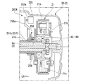
- FIG. 4 is a developed cross-sectional view along the direction of the drive shaft of the engine of the motorcycle. It is a block diagram including the main structure of this embodiment.
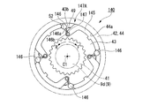
- FIG. 3 is an enlarged view of a main part of FIG. 2. It is the front view which looked at the one-way clutch shown in FIG. 2 from the axial direction. It is a principal part enlarged view of FIG.
- FIG. 7 is an operation explanatory diagram of FIG. 6. It is the front view which looked at 2nd embodiment of the said one-way clutch from the axial direction.
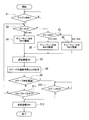
- FIG. 9 is an operation explanatory diagram of FIG. 8. It is a flowchart which shows the process of the swing back control part of ECU of the said engine.
- FIG. 1 shows the relationship between crank reverse rotation torque and crank angle.
- (B) shows the relationship between the crank angle and the stage.
- (C) shows the change in the crank angular speed during the reverse rotation of the crank.
- It is sectional drawing in alignment with the axial direction of 3rd embodiment of the locking action restriction
- It is a time chart which shows the propriety of the lock operation of the command signal of the lock operation restriction device of Drawing 12, and the one-way clutch.
- the body frame 102 is formed by integrally joining a plurality of types of steel materials by welding or the like.
- the vehicle body frame 102 extends a single main tube 108 downward and rearward from a head pipe 103 that supports the front wheel suspension system so as to be steerable, and constitutes a low portion between the head pipe 103 and a seat 109 for seating an occupant.
- a pivot bracket 110 extends below the rear end portion of the main tube 108, and a front end portion of a swing arm 112 of a rear wheel suspension system is supported on the pivot bracket 110 so as to be swingable up and down.
- a seat frame 113 extends above and behind the rear end of the main tube 108, a seat 109 is disposed on the seat frame 113, and a rear wheel suspension rear cushion is disposed between the seat frame 113 and the swing arm 112. 114 is arranged.
- the motorcycle 101 includes a front wheel 104, a front fork 105, a steering stem 106, a steering handle 107, and a rear wheel 111.
- an engine 1 which is a prime mover of the motorcycle 101 is supported.
- the engine 1 is an air-cooled single-cylinder engine in which a rotation center axis (crank axis) C1 of the crankshaft 9 is disposed along the left-right direction.
- the cylinder 3 protrudes substantially horizontally (in detail, slightly upward) from the front end of the crankcase 2 toward the front.
- the crankcase 2 is divided into a left case half 2a and a right case half 2b with a dividing plane (for example, a vehicle body left and right center plane) orthogonal to the left and right direction as a boundary.
- a left case cover 24 and a right case cover 25 that constitute parts of the left case half 2a and the right case half 2b are attached to the outside of the left case half 2a and the right case half 2b.
- Reference sign CL in the figure indicates the left and right center line of the engine 1 (and the vehicle body).
- the crankcase 2 also serves as a transmission case that accommodates a manual transmission (hereinafter simply referred to as a transmission) 4. Inside the engine 1 including the crankcase 2, engine oil is circulated and stirred as appropriate.
- a cylinder body 3a, a cylinder head 3b, and a head cover 3c are connected in order from the crankcase 2 side.
- a piston 8 is fitted in the cylinder bore 3d of the cylinder body 3a so as to be able to reciprocate.
- the piston 8 is connected to the crankpin 9a of the crankshaft 9 via a connecting rod 8a.
- the crankshaft 9 includes left and right crank webs 9b that support the crank pins 9a, left and right journal portions 9c that protrude left and right from the left and right crank webs 9b, and left and right extensions that extend further left and right outward from the left and right journal portions 9c.
- a shaft 9d transmission shaft).
- a cam drive sprocket 12 is provided on the base end side of the left extension shaft 9d.
- the camshaft 11 in the cylinder head 3 b is driven in conjunction with the crankshaft 9 via a chain transmission mechanism including the cam drive sprocket 12.
- the engine 1 includes a cam chain chamber 15 provided in the left side portion of the cylinder 3, a spark plug 17 attached to the cylinder head 3b, a throttle body 18 connected to the upper side (intake side) of the cylinder head 3b, and a lower side of the cylinder head 3b. It has an exhaust pipe 19 connected to the side (exhaust side).
- the rotational power of the crankshaft 9 is transmitted to two clutches 21 and 22 (hereinafter referred to as a centrifugal clutch 21 and a multi-plate clutch 22) housed on the right side in the crankcase 2 and a transmission housed in the rear part in the crankcase 2. 4 is output to the engine output portion 23 on the left side of the rear portion of the crankcase 2.
- the engine output unit 23 is linked to a rear wheel 111 that is a driving wheel via a chain transmission mechanism 23a.
- the crankshaft 9 side may be referred to as the upstream side
- the engine output portion 23 side may be referred to as the downstream side.
- the centrifugal clutch 21 has a bottomed cylindrical shape that opens to the right, and is supported on the right end of the crankshaft 9 so as to be relatively rotatable, and on the inner peripheral side of the clutch outer 21a.
- the clutch inner 21b is supported on the right end portion of the crankshaft 9 so as to be integrally rotatable, and a plurality of centrifugal weights 21c are supported on the inner peripheral side of the clutch outer 21a so as to be able to expand and operate on the clutch inner 21b.
- a centrifugal oil filter 26 is formed on the right side of the clutch inner 21b.
- the centrifugal weights 21c are separated from the inner peripheral surface of the clutch outer 21a when the crankshaft 9 is stopped and rotated at a low speed, so that the centrifugal clutch 21 is in a disconnected state where power cannot be transmitted.
- Each centrifugal weight 21c is expanded as the rotational speed (rotational speed) of the crankshaft 9 increases, and frictionally engages with the inner peripheral surface of the clutch outer 21a at a predetermined rotational speed or more to transmit power to the centrifugal clutch 21. Make the connection possible.
- a cylindrical inner peripheral side collar portion 41 is provided on the right side at the center of the clutch outer 21a.
- a one-way clutch 40 is fitted on the outer periphery of the inner peripheral side collar portion 41.
- a cylindrical outer peripheral side collar portion 42 protruding from the left side of the clutch inner 21b is fitted.
- the outer peripheral side collar portion 42 includes an outer ring 44 in the one-way clutch 40.
- the one-way clutch 40 has a lock operation limiting device 47A described later.
- the one-way clutch 40 does not transmit torque even if the clutch inner 21b and the crankshaft 9 are forwardly rotated (corresponding to the rotation during engine operation) prior to the clutch outer 21a, and does not transmit torque to the clutch outer 21a. Thus, the clutch inner 21b and the crankshaft 9 are idled.
- the one-way clutch 40 has its rotational speed when the clutch outer 21a tries to rotate forward (or when the clutch inner 21b and the crankshaft 9 try to reversely rotate with respect to the clutch outer 21a) prior to the clutch inner 21b and the crankshaft 9. Is less than the predetermined value, the lock operation restricting device 47A operates to keep the free state and transmit torque without rotating the clutch outer 21a with respect to the clutch inner 21b and the crankshaft 9.
- the one-way clutch 40 enters a later-described one-way operation state when the rotational speed exceeds a predetermined value, and when the outer clutch member 21a tries to rotate forward in this state prior to the inner clutch member 21b and the crankshaft 9, a later-described roller 46
- the (moving body) is locked so that torque can be transmitted between the inner ring 43 and the outer ring 44.
- the clutch outer 21a, the clutch inner 21b, and the crankshaft 9 can be normally rotated integrally.
- a cylindrical transmission cylinder 21d extending leftward is provided on the left side of the center of the clutch outer 21a.
- a primary drive gear 21e is provided on the left end side of the transmission cylinder 21d so as to be integrally rotatable.
- the primary drive gear 21e meshes with a primary driven gear 22e supported on the right side of the main shaft 5 located behind the crankshaft 9 so as to be relatively rotatable.
- the main shaft 5 and the counter shaft 6 of the transmission 4 are arranged in order from the front side behind the crankshaft 9.
- the main shaft 5 and the counter shaft 6 are arranged with their respective rotation center axes C3 and C4 along the left-right direction (in parallel with the crank axis C1).
- a kick spindle 16 is disposed below the counter shaft 6.
- the right end portion of the main shaft 5 terminates to the left of the right end of the centrifugal clutch 21, and the multi-plate clutch 22 is coaxially supported on the right end portion.
- the multi-plate clutch 22 is a transmission clutch, and has a bottomed cylindrical shape that opens to the right and is supported on the right end of the main shaft 5 so as to be relatively rotatable, and an inner periphery of the clutch outer 22a. And a plurality of clutch plates 22c that are stacked in the axial direction between the outer clutch member 22a and the inner clutch member 22b.
- a primary driven gear 22e is supported on the left side of the bottom wall of the clutch outer 22a so as to be integrally rotatable.
- the multi-plate clutch 22 presses the clutch plates 22c by the urging force of the diaphragm spring 22d and frictionally engages them.
- the multi-plate clutch 22 temporarily releases the pressure contact of each clutch plate 22c in conjunction with a shift operation of a shift pedal (not shown), thereby making the shift change of the transmission 4 smoother.
- the transmission 4 includes a main shaft 5 and a counter shaft 6, and a transmission gear group 7 supported across both shafts 5 and 6.
- the rotational power of the crankshaft 9 is transmitted from the main shaft 5 to the countershaft 6 via an arbitrary gear of the transmission gear group 7.
- the left end portion of the counter shaft 6 protrudes to the left side of the rear portion of the crankcase 2 and becomes an engine output portion 23.
- the transmission gear group 7 is composed of gears corresponding to the number of shift stages respectively supported by the main shaft 5 and the counter shaft 6.
- the transmission 4 is configured as a constantly meshing type in which the corresponding gears of the transmission gear group 7 are always meshed between the main shaft 5 and the counter shaft 6.
- Each gear supported by the main shaft 5 and the counter shaft 6 includes a free gear that can rotate relative to the shaft that supports the gear, a fixed gear that can rotate integrally with the shaft that supports the gear, and the gear. And a slide gear that is spline-fitted to a shaft that supports the shaft.
- the transmission 4 moves the slide gear by the operation of a change mechanism (not shown), and selects a gear train corresponding to the gear position.
- a second gear train 7b, a fourth gear train 7d, a third gear train 7c, and a first gear train 7a are arranged in order from the left side of the transmission gear group 7.
- an ACG starter 27 (generator device) is coaxially supported.
- the ACG starter 27 is a three-phase AC generator motor, and functions as a starter motor that starts the engine 1 and also functions as an AC generator that generates power as the engine 1 is operated.
- the operation of the ACG starter 27 is controlled by an ECU (Electronic Control Unit) 60 (control device) shown in FIG.
- the ACG starter 27 is of a so-called outer rotor type, has a bottomed cylindrical shape that opens to the left, and is supported by the left end of the crankshaft 9 so as to be integrally rotatable, and an outer rotor 27a. And a stator 27b that is disposed on the inner peripheral side and is fixedly supported by the outer wall of the left case half 2a. A plurality of magnets 27c arranged in the circumferential direction are fixed to the inner peripheral side of the outer rotor 27a. A plurality of coils 27d arranged in the circumferential direction are formed on the outer peripheral side of the stator 27b.
- the ACG starter 27 has a rotor angle sensor unit 28 b that holds a plurality of rotor angle sensors 28 attached to a stator 27 b with fastening members 28 a such as screws.
- the rotor angle sensor 28 is used for energization control with respect to the coil 27d of the stator 27b, and one rotor angle sensor 28 is provided corresponding to each of the U phase, V phase, and W phase of the ACG starter 27.
- the rotor angle sensor 28 also functions as an ignition pulser (pulser sensor) that detects one circumferential position of the outer rotor 27a as an ignition timing.
- the rotor angle sensor 28 is configured by a Hall IC or a magnetoresistive (MR) element.
- the ACG starter 27 functions as a starter motor when the engine is started.
- the ACG starter 27 is supplied with electric power from a battery (not shown) via the motor drive circuit 61 of the ECU 60, and rotates the crankshaft 9 (forward rotation drive) to crank the engine 1.
- the rotation speed of the crankshaft 9 is less than the connection rotation speed of the centrifugal clutch 21, and the one-way clutch 40 does not transmit torque at this rotation (forward rotation). Therefore, the cranking rotational motion is not transmitted to the multi-plate clutch 22, the transmission 4, and the like on the downstream side of the transmission path from the clutch outer 21 a that is the driven member of the centrifugal clutch 21.
- the ACG starter 27 functions as an AC generator that is driven by the rotation of the crankshaft 9 to generate electric power when the start of the engine 1 is confirmed, for example, when the rotation speed of the crankshaft 9 becomes equal to or higher than idling. This power generation charges the battery and supplies power to various electrical components. At this time, the one-way clutch 40 does not transmit torque. However, if the rotation speed of the crankshaft 9 is equal to or higher than the connection rotation speed of the centrifugal clutch 21, the centrifugal clutch 21 enters a connected state and the crankshaft 9 is located downstream of the transmission path. Is transmitted.
- the kick spindle 16 along the left-right direction of the kick starter 16A of the engine 1 is disposed below the rear part of the crankcase 2.
- the right end portion of the kick spindle 16 protrudes to the right side of the rear portion of the crankcase 2, and the base end portion of the kick arm 16a is attached to the protruding portion.
- a kick drive gear 16b and a meshing mechanism 16c are coaxially supported on the left side of the kick spindle 16 facing the crankcase 2.
- the kick drive gear 16b rotates integrally with the kick spindle 16 via the meshing mechanism 16c only when the kick spindle 16 rotates in one direction by stepping on the kick arm 16a.
- the kick drive gear 16b meshes with the driven gear of the first gear train 7a.
- the rotational movement of the kick drive gear 16b is input as forward rotation to the clutch outer 21a of the centrifugal clutch 21 through the first speed gear train 7a, the main shaft 5, the multi-plate clutch 22, the primary driven gear 22e, and the primary drive gear 21e. .
- the one-way clutch 40 is in a one-way operation state, and when the one-way clutch 40 is locked by further forward rotation, forward torque is applied from the clutch outer 21a to the clutch inner 21b and the crankshaft 9. Can be transmitted. That is, cranking of the engine 1 by the kick starter 16A becomes possible.
- the limit of the lock operation of the one-way clutch 40 and the one-way operation state which will be described later, are switched at a rotation speed higher than the rotation range of the swingback and within the rotation assumption area of the kick starter 16A. Is set as follows.
- the one-way clutch 40 has an annular shape coaxial with the crankshaft 9, and an inner ring 43 that is externally fitted to the inner peripheral side collar portion 41 of the clutch outer 21 a so as to be integrally rotatable,
- the outer ring 44 is provided integrally with the outer peripheral side collar portion 42 of the clutch inner 21 b, and the retainer 45 is disposed between the inner ring 43 and the outer ring 44.
- the axial direction of the one-way clutch 40 is referred to as a clutch axial direction
- the radial direction is referred to as a clutch radial direction
- the circumferential direction is referred to as a clutch circumferential direction.
- An arrow F in FIG. 5 indicates the normal rotation direction of the crankshaft 9.
- An arrow R in FIG. 5 indicates the reverse direction of the crankshaft 9.
- the outer ring 44 may not be integral with the outer collar portion 42 but may be fitted into the outer collar portion 42 so as to be integrally rotatable.
- the cage 45 includes a plurality of rollers 46 that are torque transmission elements between the inner ring 43 and the outer ring 44, and a plurality of coil springs (hereinafter simply referred to as springs) 47 that urge each roller 46 from the normal rotation direction to the reverse rotation direction. And a plurality of weights 48 that receive centrifugal force due to rotation on the inner ring 43 side and press each roller 46 outward in the clutch radial direction to move each roller 46 to a position where the one-way clutch 40 operates in one way. Hold at equal intervals in the direction.
- the retainer 45 can rotate integrally with the inner ring 43 by engaging a plurality of inner circumferential convex portions 45 a with the outer circumferential concave portion 43 a of the inner ring 43.
- a plurality of rollers 46, springs 47 (biasing members) and weights 48 together with the cage 45 also rotate integrally with the inner ring 43.
- the outer ring 44 forms a flat inner circumferential cylindrical surface 44a.
- the inner ring 43 forms a plurality of outer peripheral cam surfaces 43b that guide the roller 46, which is rolling between the inner ring 43 and the inner peripheral cylindrical surface 44a, to a non-rolling state (locked state).
- Each outer peripheral cam surface 43b is slightly inclined with respect to the tangential direction of the inner ring 43 so as to approach the inner peripheral cylindrical surface 44a toward the forward rotation direction, thereby forming a shape that functions as a one-way.
- the roller 46 is moved depending on the rotation direction of the inner ring 43, and the roller 46 is put in a rolling state (released state) without being pressed, or the roller 46
- a wedge-shaped space portion 49 is formed that enables switching between being pressed and placed in a non-rolling state (locked state).
- the roller 46 In each wedge-shaped space 49, the roller 46 is locked by the reverse rotation of the inner ring 43 with respect to the outer ring 44 (rotation in the direction of arrow R or forward rotation of the outer ring 44 with respect to the inner ring 43 (rotation in the direction of arrow F)). Thereby, torque transmission between the inner ring 43 and the outer ring 44 can be performed via the plurality of rollers 46.
- the rollers 46 In the normal rotation of the inner ring 43 with respect to the outer ring 44 (or the reverse rotation of the outer ring 44 with respect to the inner ring 43), the rollers 46 are in the released state in each wedge-shaped space 49, and torque transmission between the inner ring 43 and the outer ring 44 becomes impossible.
- the retainer 45 is formed with a plurality of weight operation surfaces 51 that guide each weight body 48 that receives centrifugal force when the inner ring rotates to move in the forward direction as the clutch body 48 moves outward in the clutch radial direction.
- a plurality of recesses 52 for entering the inner side in the clutch radial direction of the weight body 48 are formed in a portion located on the inner side in the clutch radial direction of each weight operating surface 51.
- each recess 52, the outer peripheral cam surface 43 b adjacent to the forward rotation direction of the recess 52, the weight operating surface 51, and the portion surrounded by the inner peripheral cylindrical surface 44 a of the outer ring 44 can move the roller 46 and the weight body 48. It is comprised as the accommodation space part 53 (space part) to accommodate.
- the forward rotation direction side of the accommodation space 53 is configured as a wedge-shaped space 49.
- each roller 46 is pushed in the reverse direction side of the accommodation space 53 by the urging force of the spring 47 when not pressed from the weight body 48.
- the outer peripheral surface of the roller 46 forms a gap between at least one of the outer peripheral cam surface 43 b and the inner peripheral cylindrical surface 44 a and the outer peripheral surface of the roller 46.
- the roller 46 is not pressed against the wedge-shaped space 49 and can always roll. That is, when each roller 46 is in a position where it is pushed into the reverse direction side of the accommodation space 53, there is no one-way operation.
- each weight body 48 moves to the outer peripheral side along the weight operation surface 51, and the corresponding roller 46 is moved. It is moved in the forward rotation direction against the urging force of the spring 47.
- the roller 46 moves by a predetermined amount in the forward rotation direction and reaches a predetermined position (one-way operation position) of the outer peripheral cam surface 43b, so that the roller 46 is in contact with the outer peripheral cam surface 43b and the inner peripheral cylindrical surface 44a. Become. In this state, when the inner ring 43 rotates in the reverse direction, the roller 46 is brought into pressure contact with the wedge-shaped space portion 49 and enters a non-rolling state.
- the roller 46 is moved by a predetermined amount in the forward rotation direction by a pressure generated by the movement of the weight body 48 in the accommodating space 53 to the outside in the clutch radial direction and reaches a predetermined position on the outer circumferential cam surface 43b.
- the state in contact with the surface 43b and the inner peripheral cylindrical surface 44a is referred to as a one-way operation state of the one-way clutch 40.
- the roller 46 is pressed against the wedge-shaped space 49 by the reverse rotation of the inner ring 43 with respect to the outer ring 44 (or the normal rotation of the outer ring 44 with respect to the inner ring 43) from the one-way operation state, and the non-rolling state is established between the inner ring 43 and the outer ring 44.
- the fact that torque transmission is possible is referred to as locking operation of the one-way clutch 40.
- the roller 46 In the normal rotation of the inner ring 43 with respect to the outer ring 44 (or the reverse rotation of the outer ring 44 with respect to the inner ring 43), the roller 46 is not pressed against each wedge-shaped space 49 regardless of whether or not the one-way operation is performed, and can always roll. (The one-way clutch 40 is not locked), and torque transmission between the inner ring 43 and the outer ring 44 becomes impossible.
- each roller 46 When centrifugal force enough to move each roller 46 to the position where the one-way operation state is achieved against the urging force of the spring 47 does not act on each weight 48 (corresponding to when the clutch outer 21a stops rotating and rotates at a low speed).
- the one-way clutch 40 is not in a one-way operation state, and the roller 46 does not come into pressure contact with the wedge-shaped space 49 even when the inner ring 43 is rotated reversely with respect to the outer ring 44 (or the outer ring 44 is rotated forward with respect to the inner ring 43).
- the torque transmission between the inner ring 43 and the outer ring 44 becomes impossible.
- the weight 48, the recess 52 of the inner ring 43 that guides the movement of the weight 48, the spring 47, the retainer 45 that holds the spring 47, and the roller 46 limit the locking operation of the one-way clutch 40 according to the rotational speed of the inner ring 43.
- the lock operation limiting device 47A is configured.
- the cage 145 of the one-way clutch 140 supports a plurality of weight bodies 146 (moving bodies) that are torque transmission elements between the inner ring 43 and the outer ring 44 so as to be swingable at equal intervals in the clutch circumferential direction.
- Each weight main body 146 that receives the centrifugal force due to the rotation of the inner ring 43 is swung toward the wedge-shaped space 49. That is, the weight main body 146 serves as a torque transmitting element that is press-contacted between the inner ring 43 and the outer ring 44 and a weight body that operates by receiving centrifugal force.
- Each weight main body 146 integrally has a swing arm 146a extending incline in the forward rotation direction and on the inner peripheral side of the clutch.
- the tip end portion 146b of the swing arm 146a is supported by the retainer 145 so as to be swingable.
- a plurality of torsion coil springs (hereinafter simply referred to as springs) 147 for urging the weight main body 146 to the side away from the wedge-shaped space 49 in the reverse rotation direction are attached to the distal end portion 146b of the swing arm 146a.
- the cage 145 can rotate integrally with the inner ring 43.
- a plurality of weight main bodies 146 and springs 147 (biasing members) together with the cage 145 also rotate integrally with the inner ring 43.
- Each weight main body 146 is pushed into the corresponding recess 52 by the urging force of the spring 147 when a centrifugal force of a predetermined level or more is not applied, such as when the clutch outer 21a stops rotating or rotates at a low speed. At this time, each weight main body 146 is detached from the wedge-shaped space 49, and a gap is formed between the outer peripheral cam surface 43b and the inner peripheral cylindrical surface 44a. In this state, regardless of whether the inner ring 43 rotates forward or backward, the weight main body 146 does not contact the outer peripheral cam surface in the wedge-shaped space 49, and the one-way operation state is not achieved.
- each weight body 146 swings toward the corresponding wedge-shaped space 49 and comes into contact with the outer peripheral cam surface 43b and the inner peripheral cylindrical surface 44a (locking). Operation). In this state, the weight main body 146 is pressed against the wedge-shaped space 49 by the reverse rotation of the inner ring 43 with respect to the outer ring 44 (or the normal rotation of the outer ring 44 with respect to the inner ring 43), and torque transmission between the inner ring 43 and the outer ring 44 becomes possible.
- the weight main body 146 In the normal rotation of the inner ring 43 with respect to the outer ring 44 (or the reverse rotation of the outer ring 44 with respect to the inner ring 43), the weight main body 146 is not pressed against the wedge-shaped space 49 regardless of the rotational speed, and torque transmission between the inner ring 43 and the outer ring 44 is achieved. Becomes impossible.
- the weight body 146, the swing arm 146a, the spring 147, and the retainer 145 that holds the spring 147 are configured to restrict the lock operation of the one-way clutch 140 according to the reverse rotation speed of the inner ring 43 (the lock operation restriction device 47A).
- the weight main body 146 has the functions of both the weight body 48 and the roller 46 of the first embodiment.
- the ECU 60 includes a motor drive circuit 61 that controls driving and power generation of the ACG starter 27, an idle stop control unit 62 that automatically stops the engine 1 (idle stop), and an ACG starter immediately after the idle stop. And a swing back control unit 63 that performs reverse rotation (swing back) of the crankshaft 9 by 27 reverse rotation driving.
- the ECU 60 includes a throttle sensor 31 that detects the opening of a throttle valve (not shown) of the throttle body 18, a vehicle speed sensor 32 that detects the vehicle speed from the rotational speed of the wheels, and a warm-up state of the engine 1.
- a temperature sensor 33 that detects the oil temperature and a battery sensor 34 that detects the battery current and voltage as the state of charge of the battery are connected.
- the rotor angle sensor 28 also serves as a crank angle sensor that detects a crank rotation speed and a rotation angle.
- the ECU 60 is connected to an ignition device 35 including an ignition plug 17 and a fuel injection device 36 including an injector 18a of the throttle body 18, and the occupant selects whether to perform idle stop control.
- An idle stop switch 37 to be activated and an indicator 38 that is lit when idle stop control is selected or idle stop is connected.
- the motor drive circuit 61 includes, for example, a power FET (Field-Effect-Transistor), rectifies the three-phase alternating current generated by the ACG starter 27, and regulates the battery power when driving the ACG starter 27. Supply.
- a power FET Field-Effect-Transistor
- the idle stop control unit 62 automatically stops the engine 1 by stopping the ignition of the spark plug 17 and the fuel injection of the injector 18a when the automatic stop permission condition of the engine 1 is satisfied when the idle stop control is selected. stop).
- the idle stop control unit 62 drives the ACG starter 27 to crank the engine 1 when the restart permission condition of the engine 1 is satisfied, and also performs ignition of the spark plug 17 and fuel injection of the injector 18a.
- the engine 1 is restarted and the engine 1 is automatically restarted.
- the ECU 60 performs the idle stop control only when it is recognized that the state of charge of the battery is sufficient to restart the engine 1.
- the swing back control unit 63 drives the ACG starter 27 in reverse to improve the restartability of the engine 1 after idling stop, and the crankshaft 9 is in front of the compression top dead center just before idling stop (during reverse rotation). Reverse to the rotation angle (swing back).
- the swingback control unit 63 extends the running distance of the crankshaft 9 when the engine 1 is restarted, and reverses the crankshaft 9 to a position where the forward rotation torque for getting over the compression top dead center is small. Thereafter, the idle stop control unit 62 drives the ACG starter 27 to rotate in the forward direction, causes the crankshaft 9 to rotate in the forward direction again, and operates the ignition device 35 and the fuel injection device 36 again to restart the engine 1.
- the swingback control unit 63 includes a stage determination unit 64, a stage passage time detection unit 65, a reverse rotation control unit 66, and a duty ratio setting unit 67.
- the stage determination unit 64 divides one revolution of the crankshaft 9 into 36 stages # 0 to # 35 based on the output signal of the rotor angle sensor 28, and generates a pulse signal generated by the rotor angle sensor 28 as an ignition pulser.
- the current stage is determined using the detection timing as a reference stage (stage # 0).
- the stage passage time detection unit 65 detects the passage time ⁇ tn of this stage based on the time from when the stage determination unit 64 determines a new stage until the next stage is determined.
- the reverse rotation control unit 66 generates a reverse rotation drive command for the ACG starter 27 based on the determination result by the stage determination unit 64 and the passage time ⁇ tn detected by the stage passage time detection unit 65.
- the duty ratio setting unit 67 dynamically controls the duty ratio of the gate voltage supplied to each power FET of the motor drive circuit 61 based on the determination result by the stage determination unit 64.
- FIG. 11A shows the relationship between the cranking torque (reverse load) required for reversing the crankshaft 9 and the crank angle.
- the cranking torque suddenly increases immediately before reaching the compression top dead center (during reverse rotation).
- FIG. 11B shows the relationship between the crank angle and the stage.
- FIG. 11C shows the change in the angular velocity of the crankshaft 9 during reverse rotation.
- step S1 swing back control unit 63 refers to the current stage already determined in stage determination unit 64 in steps S2 and S3. If the current stage is any one of stages # 0 to # 11, the process proceeds to step S4. If the current stage is any one of stages # 12 to # 32, the process proceeds to step S5. If the current stage is other than that (that is, any one of stages # 33 to # 35), the process proceeds to step S6. In step S4 and step S6, the duty ratio setting unit 67 sets the duty ratio of the drive pulse to 70%. In step S5, the duty ratio setting unit 67 sets the duty ratio of the drive pulse to 80%.
- step S7 the motor drive circuit 61 starts reverse energization by controlling each power FET with the duty ratio set in any of steps S4 to S6.
- step S8 the passage time ⁇ tn of the passed stage #n is measured by the stage passage time detector 65.
- step S9 the reverse rotation control unit 66 determines whether or not the crankshaft 9 has passed stage # 0 (ie, near the top dead center). If it has not passed stage # 0, in step S11, the ratio between the passing time ⁇ tn of stage #n that passed immediately before and the passing time ⁇ tn-1 of stage # (n ⁇ 1) that passed immediately before “#” “ ⁇ tn / ⁇ tn ⁇ 1” (hereinafter referred to as a passing time ratio) is compared with a reference value (4/3 in the present embodiment). If the passage time ratio “ ⁇ tn / ⁇ tn ⁇ 1” does not exceed the reference value, the process returns to step S2 to continue the reverse drive, and the above-described processes are repeated in parallel.
- a passing time ratio 4/3 in the present embodiment
- the engine stop position that is, the reverse rotation start position is from an intermediate position (exhaust top dead center) between the previous compression top dead center and the next compression top dead center.
- the side near the next compression top dead center in other words, when it is in the process from passing through the exhaust top dead center (during normal rotation) to reaching the compression top dead center, the ACG starter 27 has a duty of 70%.
- the crankshaft 9 can pass through the stage # 0 (exhaust top dead center) despite being driven in reverse at a ratio.
- step S9 the process proceeds to step S10, and it is determined whether or not the crankshaft 9 has reached stage # 32. If it is determined that the crankshaft 9 has reached the stage # 32, the reverse energization is stopped in step S12. Thereafter, the crankshaft 9 is further rotated in the reverse direction by the inertial force and then stopped.
- the reverse rotation start position is closer to the previous compression top dead center than the intermediate position between the previous compression top dead center and the next compression top dead center,
- the ACG starter 27 is driven in reverse at a duty ratio of 70%, so FIG.
- the reverse load increases immediately before reaching stage # 0 (during reverse rotation), and the angular velocity of the crankshaft 9 decreases.
- step S11 when it is determined that the passage time ratio “ ⁇ tn / ⁇ tn ⁇ 1” is 4/3 or more which is the reference value, the reverse energization is stopped in step S12, and substantially simultaneously with this, the crankshaft 9 The reverse rotation stops.
- the crankshaft 9 it is determined whether or not the crankshaft 9 has passed the top dead center equivalent angle and whether or not the angular velocity of the crankshaft 9 has decreased during reverse rotation after the engine is stopped. If the crankshaft 9 passes the top dead center at the time of reverse rotation, the reverse rotation energization is terminated immediately thereafter, and the reverse rotation energization is also ended when the angular velocity of the crankshaft 9 is reduced by a predetermined amount due to an increase in the reverse load. . As a result, regardless of the reverse rotation start position, the crankshaft 9 can be returned to a position before the previous compression top dead center (during reverse rotation) and to a low compression reaction force (cylinder internal pressure).
- the angular speed of the crankshaft 9 is detected based on the output of the rotor angle sensor 28 that detects the rotor angle (stage) of the ACG starter 27, so the angle of the crankshaft 9 is detected. There is no need to provide a separate crank angle sensor to reduce the number of parts.
- the engine 1 restricts the lock operation for the torque transmission in the one-way clutches 40 and 140 when the crankshaft 9 is reversely rotated at a low speed in the swingback control in which the crankshaft 9 is reversely rotated to a predetermined position after the engine is stopped. It has devices 47A and 147A.
- the engine brake can be used without greatly changing the configuration of the existing internal combustion engine having the centrifugal clutch 21 and the one-way clutches 40 and 140 in the transmission path from the crankshaft 9 to the engine output unit 23, and the centrifugal clutch.
- the swing start control by the ACG starter 27 is performed while suppressing the loss of the reverse rotation torque of the ACG starter 27, while the kick starter 16A using the driven member (clutch outer 21a) on the engine output unit 23 side of 21 can be installed. It is possible to reduce the starting torque load of the ACG starter 27 when the engine is restarted.
- the lock operation restriction device 247A of the third embodiment is different from the one-way clutch 40 in that the weight body 48 is eliminated and an elastic plate 48 ′ made of a leaf spring, a rubber plate or the like is provided in the open portion of the recess 52 in the clutch circumferential direction. Install along. The roller 46 moves from the state on the elastic plate 48 ′ in the wedge-shaped space 49 according to the rotation direction of the inner ring 43.
- a lock operation restriction device 247A that has the restriction piece 257 and moves the restriction piece 257 to restrict the lock operation of the one-way clutch 40 ′ will be described.
- the lock operation restriction unit (not shown) of the swing back control unit 63 senses an electric signal (“swing back signal” in FIG. 13) corresponding to the reverse rotation instruction signal for the ACG starter 27, the lock operation restriction device 247A It is driven by the lock operation restricting unit to restrict the lock operation of the one-way clutch 40 ′.
- the lock operation restriction device 247A extends between the solenoid 255 that is energized and controlled by the lock operation restriction unit, the restriction member 256 that is activated by the protrusion of the plunger 255a when the solenoid 255 is energized, and the plunger 255a and the restriction member 256.
- the solenoid 255 is supported in the right case cover 25 and causes the plunger 255a to protrude leftward.
- the solenoid 255 is a push type that causes the plunger 255a to protrude when energized.
- the input end side of the rocker arm 256a abuts on the distal end portion of the plunger 255a.
- the output end of the rocker arm 256 a abuts on the left side surface of the limiting member 256.
- the limiting member 256 is urged to the left by the urging member 258.
- the urging member 258 is a coil spring that is fitted in a stretchable manner with a gap on the outer periphery of the transmission cylinder 21d. As shown by “solenoid input” in FIG. 13, the energization signal to the solenoid 255 is turned “ON” together with the “swing back signal”, and the solenoid 255 is energized by the lock operation restriction unit.
- the limiting member 256 is provided with a limiting piece 257 that protrudes to the right. When the limiting member 256 moves to the right, the limiting piece 257 is inserted into the wedge-shaped space 49.
- the restricting piece 257 is inserted into the wedge-shaped space 49 with the roller 46 (moving body) pushed in the reverse direction as shown in FIG. 16, and the roller 46 moves in the forward direction (the one-way clutch 40 ′ is one-way). Limit the movement to the position where it will be activated.
- the restricting piece 257 has an inclined side 257a that can be brought into sliding contact with the roller 46 when inserted into the wedge-shaped space 49, and can facilitate the quick movement of the roller 46 while facilitating insertion.
- the lock operation restriction device 247A disables the lock operation of the one-way clutch 40 ′ when “swing back” and “solenoid input” are “ON”, as indicated by “lock operation” in FIG. When the “swing back” and “solenoid input” are “OFF”, the one-way clutch 40 ′ can be locked.
- the lock operation limiting device is configured so that the limiting piece 257 is moved to the forward rotation direction side of the roller 46 in the wedge-shaped space 49 in a state where the roller 46 is pushed in the forward rotation direction (including the one-way operation state of the one-way clutch 40 ′). Even when the roller 46 is inserted, the roller 46 may be moved in the reverse rotation direction while sliding the inclined side 257a on the roller 46, and the change to the one-way operation state of the one-way clutch 40 ′ may be limited as described above. . Thereby, it can be used for releasing the lock operation of the mechanical one-way clutch.
- both the lock operation restriction devices 47A and 247A may be employed together to control the energization to the solenoid 255. . That is, the lock operation restriction device 247A may be applied to the one-way clutch 40.
- the lock operation limiting device may be configured to limit the movement of the weight body 48 instead of the moving body (roller 46). Further, the one-way clutch 140 can be combined with the lock operation limiting device 247A.
- the lock operation restriction device 347A includes an electromagnet 355 that is energized and controlled by a lock operation restriction unit (not shown), a restriction member 356 that is activated by energization of the electromagnet 355, and a rocker arm 356a that extends between the electromagnet 355 and the restriction member 356.
- the electromagnet 355 is supported in the right case cover 25 and is adjacent to the left side of the magnet 356b built in the input end side of the rocker arm 356a.
- the output end of the rocker arm 356 a contacts the left side surface of the limiting member 356.
- a magnet 356b that can be attracted by magnetization of the electromagnet 355 is built in the tip of the rocker arm 356a.
- the limiting member 356 is disposed adjacent to the left side of the one-way clutch 40 and causes the limiting piece 257 to protrude rightward.
- the restricting member 356 is urged to the left by the urging member 258, and the left side surface is brought into contact with the output end portion of the rocker arm 356a.
- the rocker arm 356a separates the input-side magnet 356b from the electromagnet 355 by a predetermined amount.
- the mechanical one-way clutch may be used for releasing the lock operation.
- the above configuration may be applied to the one-way clutches 40 and 140, and the lock operation restriction devices 47A and 147A may be used in combination.
- FIG. 17 shows a setting concept of the operation limit of the one-way clutch according to the embodiment of the present invention, where the horizontal axis is the rotation speed of the crankshaft, the region where the operation limit of the one-way clutch is applied, the rotation speed of the swingback, and the kick The crank rotation speed is shown.
- the width of the rotational speed of the swingback is assumed in consideration of the phase of the crank and the like, and the width of the crank rotational speed due to the kick is assumed including variations in kicks of general drivers.
- the concept of setting the operation limit depends on the reverse rotation speed in the case of swingback, but in the case of the rotation action type that utilizes centrifugal force, the absolute value of the rotation speed regardless of the forward and reverse rotation. Depends on. For this reason, the setting concept is expressed using the absolute value of the rotational speed of the crankshaft on the horizontal axis.
- the one-way clutch lock operation limit and the one-way operation state are switched at a rotation speed higher than the rotation speed range of the swingback and at a rotation speed within the assumed rotation range of the kick starter 16A. Is set.
- the kick drive when starting with the kick starter, can be effectively operated in the upper rotation speed range (the region indicated by the solid line) by the one-way operation state in the expected kick starter rotation range. it can.
- a device that electrically restricts the lock operation instead of the mechanical rotation speed operation type lock operation restriction device 47A.
- the lock operation when the swing back is not performed, the lock operation is not limited, and the one-way operation state can be always set by electrical control, and the kick starter rotation assumed range It is possible to make the kick drive work effectively in all of the above (including the dotted line).
- the swingback control unit 63 includes a stage determination unit 64, a stage passage time detection unit 65, a reverse rotation control unit 66, a duty ratio setting unit 67, and a lock release control unit 68.
- the lock release control unit 68 performs a one-way clutch lock release confirmation process described later.
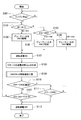
- step S101 to step S108 of this embodiment is the same as the operation from step S1 to step S8 described with reference to FIG. 10 for the second embodiment of the one-way clutch, the description thereof is omitted.
- step S109 a one-way clutch lock release confirmation step, which will be described in detail later, is performed.
- step S110 to step S113 are the same as the operations from step S9 to step S12 described with reference to FIG. 10 for the second embodiment of the one-way clutch, and thus the description thereof is omitted.
- lock release control unit 68 first resets timekeeping information “ ⁇ t” in step S191 and resets stage count information “ ⁇ n” in step S192.
- step S193 it is determined whether or not “ ⁇ t” exceeds a predetermined time T (for example, 35 msec). If “ ⁇ t” exceeds the predetermined time T, it is then determined in step S194 whether “ ⁇ n” exceeds 2. That is, it is determined whether or not it has rotated two stages after a predetermined time T after the reverse rotation drive command of the ACG starter 27.
- step S195 the process proceeds to step S91 described later, and if “NO”, the process proceeds to step S195.
- steps S195 to S199 assuming that the one-way clutch 40 has been locked since the idling stop, the reverse energization is stopped in step S195 and the forward energization is started in step S196. This forward energization is performed until the rotation angle of the crankshaft 9 reaches at least the next stage # n + 1 from the current stage #n (step S197).
- the locked state of the one-way clutch 40 in this case assumes that the roller 46 is already in a non-rolling state in an unexpected situation in the wedge-shaped space 49, for example, at an idle stop immediately after engine braking.
- the forward rotation energization in step S197 causes the inner ring 43 together with the crankshaft 9 to rotate forward by at least a predetermined angle ⁇ with respect to the outer ring 44 (see FIG. 22C).
- the predetermined angle ⁇ is set to an angle sufficient to release the pressure contact of the roller 46.
- the predetermined angle ⁇ is set to a rotation angle corresponding to at least one stage of the crankshaft 9, that is, a rotation angle of at least 10 degrees.
- step S198 forward energization is stopped in step S198, and reverse energization is started again in step S199. Then, the process returns to step S191, and the processes of steps S191 to S194 are performed again. If “YES” in the step S194, the one-way clutch 40 is unlocked at the time of idling stop. If “NO” remains in step S194, the processes in steps S195 to S199 are repeated again. Even if these processes are repeated a predetermined number of times, if the lock at the time of idling stop of the one-way clutch 40 is not released, a notifying means (not shown) is operated because an abnormality has occurred. It should be noted that after the idle stop, the control may always be performed so that the ACG starter 27 is rotated forward by one stage and then reversely rotated, and thereafter the process returns to step S191 regardless of the determination in step S194.
- steps S91 to S96 processing is performed when the one-way clutch 40 is locked during swingback.
- step S91 the decrease in the angular speed of the crankshaft 9 after the start of reverse rotation is due to reaching a point before compression top dead center (at the time of reverse rotation), or due to an unexpected lock state of the mechanical one-way clutch 40.
- the second reference value X is a value (for example, 2/1) larger than the reference value (4/3), and indicates that the angular velocity of the crankshaft 9 has decreased relatively abruptly.
- the passage time ratio “ ⁇ tn / ⁇ tn ⁇ 1” of the crankshaft 9 is monitored, and before the crankshaft 9 is reversely rotated to a predetermined angle, whether or not the one-way clutch 40 is unlocked is determined. Determine whether.
- the increase in the reverse rotation load when the one-way clutch 40 is in the locked state is expected to be the latter case because the reverse rotation load is much higher than the increase in the reverse rotation load when the crankshaft 9 is in the process of reaching the compression top dead center.
- the second reference value X corresponding to the passing time ratio “ ⁇ tn / ⁇ tn ⁇ 1” based on the maximum reverse load, the measured value of the passing time ratio “ ⁇ tn / ⁇ tn-1” exceeds the second reference value X. Whether or not the one-way clutch 40 is unlocked can be determined based on whether or not it is engaged.
- step S91 If it is determined in step S91 that the passage time ratio “ ⁇ tn / ⁇ tn ⁇ 1” is equal to or smaller than the second reference value X, the process after step S110 is performed assuming that the locked state of the one-way clutch 40 is released. Is called. The change in the angle of the crankshaft 9 at this time is shown in FIG.
- step S91 If it is determined in step S91 that the passage time ratio “ ⁇ tn / ⁇ tn ⁇ 1” exceeds the second reference value X, it is assumed that the one-way clutch 40 is in the locked state and the reverse energization is stopped in step S92.
- step S93 normal energization is started. This forward energization is performed until the rotation angle of the crankshaft 9 reaches from the current stage #n to at least the next stage # n + 1 as in step S197 (step S94).
- step S94 causes the inner ring 43 together with the crankshaft 9 to rotate forward by at least a predetermined angle ⁇ with respect to the outer ring 44 (see FIG. 22D).
- step S95 the forward energization is stopped in step S95, and the reverse energization is started again in step S96. Then, the process returns to step S91 to determine again whether or not the passage time ratio “ ⁇ tn / ⁇ tn ⁇ 1” exceeds the second reference value X. If the passage time ratio “ ⁇ tn / ⁇ tn ⁇ 1” is equal to or smaller than the second reference value X in this determination, it is determined that the one-way clutch 40 is unlocked, and the process proceeds to step S96 and subsequent steps.
- the change in the angle of the crankshaft 9 at this time is shown in FIG.
- step S91 If it is determined again in step S91 that the passage time ratio “ ⁇ tn / ⁇ tn ⁇ 1” remains higher than the second reference value X, the processes in steps S92 to S96 are repeated again. If the passage time ratio “ ⁇ tn / ⁇ tn ⁇ 1” remains above the second reference value X even after repeating these processes a predetermined number of times, a notifying means (not shown) is operated as an abnormality has occurred.
- the internal combustion engine in the above embodiment includes the ACG starter 27 that also serves as the starting motor, the centrifugal clutch 21 provided in the transmission path from the crankshaft 9 to the engine output unit 23, and the engine output unit of the centrifugal clutch 21.
- a clutch outer 21a that is a driven member on the 23 side is supported on an extension shaft 9d that is one of the transmission shafts of the transmission path, and torque is not transmitted to the clutch outer 21a when the extension shaft 9d rotates forward with respect to the clutch outer 21a.
- the one-way clutch 40 capable of transmitting torque to the clutch outer 21a during reverse rotation of the extension shaft 9d with respect to the clutch outer 21a, and the ECU 60 that drives and controls the ACG starter 27 are provided. Swing back control to reverse the That during reverse rotation of extension shaft 9d, it has a lock operation restricting device 47A for limiting the locking operation for the torque transmission.
- the engine brake can be used without greatly changing the configuration of the existing internal combustion engine having the centrifugal clutch 21 and the one-way clutch 40 in the transmission path from the crankshaft 9 to the engine output unit 23, and the centrifugal clutch While it is possible to equip the kick starter 16A using the 21 driven members, the swing back control by the ACG starter 27 that also serves as the starter motor can be performed while suppressing the loss of the reverse rotation torque of the ACG starter 27. The starting torque load of the ACG starter 27 at the time of starting can be reduced.
- the ECU 60 when the reverse rotation of the ACG starter 27 is not normally performed after the reverse rotation instruction to the ACG starter 27 in the swing back control, the ECU 60 temporarily rotates the ACG starter 27 once as the unlocking operation of the one-way clutch 40. After that, it has a lock release control unit 68 that reversely rotates the ACG starter 27 again.
- the one-way clutch 40 is locked due to an unforeseen situation during the swing-back operation, and a means for releasing this is provided to increase the reliability of the swing-back operation.
- the ACG starter 27 can be rotated forward once and then the ACG starter 27 can be reversed again to release the locked state of the torque transmission element. The loss of reverse torque can be suppressed and the reliability of the swingback operation can be increased.
- the present invention is not limited to the above-described embodiment, and for example, at least one of the centrifugal clutch 21 and the ACG starter 27 may be supported on a different shaft instead of being coaxial with the crankshaft 9.
- the present invention may be applied to an engine having a stepped or continuously variable automatic transmission instead of the manual transmission 4.
- it is good also as a structure which moves the limiting members 256 and 356 inserted in a one-way clutch with a mechanical centrifugal mechanism.
- the inner ring 43 of the one-way clutch is externally fitted on the clutch outer 21a side of the centrifugal clutch 21, and the outer ring 44 of the one-way clutch is fitted on the clutch inner 21b side.
- the arrangement is not limited to this, and the inner ring of the one-way clutch may be mounted on the clutch inner side of the centrifugal clutch, and the outer ring of the one-way clutch may be mounted on the outer clutch side of the centrifugal clutch.
- the mechanism corresponding to the lock operation limiting device based on the rotation speed of the first embodiment, the second embodiment, and the fifth embodiment is provided on the outer ring side, and the rotation speed of the outer ring becomes equal to or higher than a predetermined speed. It is replaced with a mechanism that enables the locking operation.
- the present invention is not limited to motorcycles and may be applied to three-wheel or four-wheel small vehicles.
- the present invention is not limited to an engine in which a cylinder protrudes in front of the crankcase, and may be applied to an engine in which the cylinder is raised above the crankcase.
- the structure in the said embodiment is an example of this invention, A various change is possible in the range which does not deviate from the summary of this invention.
Landscapes
- Engineering & Computer Science (AREA)
- General Engineering & Computer Science (AREA)
- Mechanical Engineering (AREA)
- Chemical & Material Sciences (AREA)
- Combustion & Propulsion (AREA)
- One-Way And Automatic Clutches, And Combinations Of Different Clutches (AREA)
- Hybrid Electric Vehicles (AREA)
Abstract
L'invention porte sur un moteur à combustion interne (1), qui comprend un dispositif de limitation d'opération de verrouillage (47A) destiné à limiter une opération de verrouillage pour la transmission de couple dans un embrayage unidirectionnel (40), lorsqu'un vilebrequin (9) tourne en sens inverse pendant une commande de retour. Le dispositif de limitation d'opération de verrouillage (47A) limite l'opération de verrouillage de l'embrayage unidirectionnel (40) en fonction de la vitesse de rotation en sens inverse du vilebrequin (9) pendant une commande de retour.
Priority Applications (1)
| Application Number | Priority Date | Filing Date | Title |
|---|---|---|---|
| CN201380072118.9A CN104968927B (zh) | 2013-02-06 | 2013-12-13 | 内燃机 |
Applications Claiming Priority (4)
| Application Number | Priority Date | Filing Date | Title |
|---|---|---|---|
| JP2013-021718 | 2013-02-06 | ||
| JP2013021718A JP6007120B2 (ja) | 2013-02-06 | 2013-02-06 | 内燃機関の始動制御装置 |
| JP2013-021717 | 2013-02-06 | ||
| JP2013021717A JP5998073B2 (ja) | 2013-02-06 | 2013-02-06 | 内燃機関 |
Publications (1)
| Publication Number | Publication Date |
|---|---|
| WO2014122857A1 true WO2014122857A1 (fr) | 2014-08-14 |
Family
ID=51299461
Family Applications (1)
| Application Number | Title | Priority Date | Filing Date |
|---|---|---|---|
| PCT/JP2013/083509 Ceased WO2014122857A1 (fr) | 2013-02-06 | 2013-12-13 | Moteur à combustion interne |
Country Status (2)
| Country | Link |
|---|---|
| CN (1) | CN104968927B (fr) |
| WO (1) | WO2014122857A1 (fr) |
Cited By (1)
| Publication number | Priority date | Publication date | Assignee | Title |
|---|---|---|---|---|
| EP3825539A4 (fr) * | 2018-09-21 | 2021-09-08 | Honda Motor Co., Ltd. | Dispositif de redémarrage de moteur |
Families Citing this family (2)
| Publication number | Priority date | Publication date | Assignee | Title |
|---|---|---|---|---|
| CN112137413A (zh) * | 2019-06-28 | 2020-12-29 | 广东美的生活电器制造有限公司 | 联轴器、旋转组件、容器及食品处理机 |
| CN111421998B (zh) * | 2020-03-31 | 2023-01-03 | 无锡爱一力机械有限公司 | 一种棘轮助力机构 |
Citations (3)
| Publication number | Priority date | Publication date | Assignee | Title |
|---|---|---|---|---|
| JP2003343404A (ja) * | 2002-05-22 | 2003-12-03 | Honda Motor Co Ltd | エンジン始動装置 |
| WO2004072504A1 (fr) * | 2003-02-13 | 2004-08-26 | Nsk-Warner K.K. | Embrayage unidirectionnel centrifuge |
| JP2008274855A (ja) * | 2007-04-27 | 2008-11-13 | Honda Motor Co Ltd | デコンプ装置を備える内燃機関および該内燃機関が搭載された自動二輪車 |
Family Cites Families (3)
| Publication number | Priority date | Publication date | Assignee | Title |
|---|---|---|---|---|
| JP4372507B2 (ja) * | 2003-02-13 | 2009-11-25 | 本田技研工業株式会社 | 回転作動型ワンウェイクラッチ |
| JP3815446B2 (ja) * | 2003-03-11 | 2006-08-30 | 株式会社デンソー | スタータ |
| JP2006316679A (ja) * | 2005-05-11 | 2006-11-24 | Yamaha Motor Co Ltd | 自動二輪車用のエンジン装置 |
-
2013
- 2013-12-13 WO PCT/JP2013/083509 patent/WO2014122857A1/fr not_active Ceased
- 2013-12-13 CN CN201380072118.9A patent/CN104968927B/zh active Active
Patent Citations (3)
| Publication number | Priority date | Publication date | Assignee | Title |
|---|---|---|---|---|
| JP2003343404A (ja) * | 2002-05-22 | 2003-12-03 | Honda Motor Co Ltd | エンジン始動装置 |
| WO2004072504A1 (fr) * | 2003-02-13 | 2004-08-26 | Nsk-Warner K.K. | Embrayage unidirectionnel centrifuge |
| JP2008274855A (ja) * | 2007-04-27 | 2008-11-13 | Honda Motor Co Ltd | デコンプ装置を備える内燃機関および該内燃機関が搭載された自動二輪車 |
Cited By (1)
| Publication number | Priority date | Publication date | Assignee | Title |
|---|---|---|---|---|
| EP3825539A4 (fr) * | 2018-09-21 | 2021-09-08 | Honda Motor Co., Ltd. | Dispositif de redémarrage de moteur |
Also Published As
| Publication number | Publication date |
|---|---|
| CN104968927B (zh) | 2017-05-24 |
| CN104968927A (zh) | 2015-10-07 |
Similar Documents
| Publication | Publication Date | Title |
|---|---|---|
| CN106014745B (zh) | 车辆用发动机的起动装置 | |
| CN104024627B (zh) | 起动系统 | |
| US9200608B2 (en) | Starter system | |
| CN104024628B (zh) | 起动系统 | |
| US9334845B2 (en) | Engine starting device | |
| JP6007120B2 (ja) | 内燃機関の始動制御装置 | |
| WO2014122857A1 (fr) | Moteur à combustion interne | |
| JP5998073B2 (ja) | 内燃機関 | |
| EP2952731A1 (fr) | Unité de moteur pourvue d'un alterno-démarreur et d'un démarreur auxiliaire pour démarrer un véhicule à selle à enfourcher | |
| JP6212781B2 (ja) | ワンウェイクラッチ | |
| CN110088457B (zh) | 用于发动机装置的驱动系统 | |
| WO2015037053A1 (fr) | Dispositif d'arrêt/redémarrage automatique de moteur à combustion | |
| JP2001132594A (ja) | エンジン自動始動装置 | |
| JP5075226B2 (ja) | エンジン始動装置 | |
| JP6413199B2 (ja) | ワンウェイクラッチ | |
| JP6623066B2 (ja) | 内燃機関冷却システム | |
| JP6116607B2 (ja) | ワンウェイクラッチ | |
| JP6249861B2 (ja) | ワンウェイクラッチ | |
| JP6759684B2 (ja) | 車両駆動部の制御装置およびプログラム | |
| JP6071736B2 (ja) | エンジン始動装置 | |
| JP6408399B2 (ja) | 内燃機関の制御装置 | |
| JP5496157B2 (ja) | エンジン制御装置 | |
| JP2010133258A (ja) | エンジン始動装置 |
Legal Events
| Date | Code | Title | Description |
|---|---|---|---|
| 121 | Ep: the epo has been informed by wipo that ep was designated in this application |
Ref document number: 13874245 Country of ref document: EP Kind code of ref document: A1 |
|
| NENP | Non-entry into the national phase |
Ref country code: DE |
|
| WWE | Wipo information: entry into national phase |
Ref document number: IDP00201504811 Country of ref document: ID |
|
| 122 | Ep: pct application non-entry in european phase |
Ref document number: 13874245 Country of ref document: EP Kind code of ref document: A1 |