WO2014122860A1 - 消費電力削減装置 - Google Patents
消費電力削減装置 Download PDFInfo
- Publication number
- WO2014122860A1 WO2014122860A1 PCT/JP2013/083897 JP2013083897W WO2014122860A1 WO 2014122860 A1 WO2014122860 A1 WO 2014122860A1 JP 2013083897 W JP2013083897 W JP 2013083897W WO 2014122860 A1 WO2014122860 A1 WO 2014122860A1
- Authority
- WO
- WIPO (PCT)
- Prior art keywords
- voltage
- unit
- switch
- detection unit
- voltage characteristic
- Prior art date
- Legal status (The legal status is an assumption and is not a legal conclusion. Google has not performed a legal analysis and makes no representation as to the accuracy of the status listed.)
- Ceased
Links
Images




Classifications
-
- H—ELECTRICITY
- H02—GENERATION; CONVERSION OR DISTRIBUTION OF ELECTRIC POWER
- H02P—CONTROL OR REGULATION OF ELECTRIC MOTORS, ELECTRIC GENERATORS OR DYNAMO-ELECTRIC CONVERTERS; CONTROLLING TRANSFORMERS, REACTORS OR CHOKE COILS
- H02P6/00—Arrangements for controlling synchronous motors or other dynamo-electric motors using electronic commutation dependent on the rotor position; Electronic commutators therefor
- H02P6/08—Arrangements for controlling the speed or torque of a single motor
- H02P6/085—Arrangements for controlling the speed or torque of a single motor in a bridge configuration
Definitions
- the present invention relates to an apparatus for reducing power consumption.
- an object of the present invention is to provide an apparatus that can reduce power consumption.
- the power consumption reduction device includes a voltage characteristic detection unit, a drive signal generation unit, a switch unit, and a switch control unit.
- the voltage characteristic detection unit is electrically connected to the power source, and detects a characteristic of a voltage supplied from the power source when a current flows inside.
- the drive signal generation unit generates a drive signal for driving the actuator based on the detection result of the voltage characteristic detection unit.
- the switch unit is connected in series with the voltage characteristic detection unit between the power source and the voltage characteristic detection unit, and can block a current flow into the voltage characteristic detection unit.
- the switch control unit controls switching of the switch unit.
- the switch control unit switches the switch unit so that current flows into the voltage characteristic detection unit during the operation mode in which the actuator is driven, and current does not flow into the voltage characteristic detection unit during the standby mode in which the actuator stops driving.
- the switch control unit has a current flowing into the voltage characteristic detection unit in the operation mode in which the actuator is driven, and in the voltage characteristic detection unit in the standby mode in which the actuator is not driven. Switch the switch so that no current flows to As a result, current flows into the voltage characteristic detector during the operation mode, and no current flows into the voltage characteristic detector during the standby mode. As a result, the power consumption of the voltage characteristic detector in the standby mode is reduced. Therefore, power consumption can be reduced.
- the power consumption reduction device includes a voltage characteristic detection unit, a detection result utilization unit, a switch unit, and a switch control unit.
- the voltage characteristic detection unit is electrically connected to the power source, and detects a characteristic of a voltage supplied from the power source when a current flows inside.
- the detection result utilization unit operates based on the detection result of the voltage characteristic detection unit.
- the switch unit is connected in series with the voltage characteristic detection unit between the power source and the voltage characteristic detection unit, and can block a current flow into the voltage characteristic detection unit.
- the switch control unit controls switching of the switch unit.
- the switch control unit prevents current from flowing into the voltage characteristic detection unit when the detection result utilization unit requires the voltage characteristic detection result, and prevents current from flowing into the voltage characteristic detection unit when the detection result utilization unit does not require the voltage characteristic detection result. Switch the switch to.
- the switch control unit causes a current to flow into the voltage characteristic detection unit when the detection result utilization unit requires the voltage characteristic detection result, and the detection result utilization unit performs the voltage characteristic detection result.
- the switch unit is switched so that no current flows into the voltage characteristic detection unit.
- current flows into the voltage characteristic detection unit when the voltage characteristic detection result is necessary, and no current flows into the voltage characteristic detection unit when the voltage characteristic detection result is unnecessary.
- the power consumption of the voltage characteristic detector when the voltage characteristic detection result is unnecessary is reduced. Therefore, power consumption can be reduced.
- a power consumption reduction device is the power consumption reduction device according to the first aspect, in which the switch control unit includes a voltage characteristic detection unit when a predetermined time elapses after the actuator stops driving. The switch part is switched so as to cut off the flow of current.
- the switch control unit is configured to switch off the current flow into the voltage characteristic detection unit when a predetermined time has elapsed since the actuator stopped driving. Switch.
- the flow of current into the voltage characteristic detection unit is interrupted when it may be surely interrupted.
- stable switching control of the switch unit can be realized.
- a power consumption reduction device is the power consumption reduction device according to the first aspect or the third aspect, wherein the actuator is configured to drive at least one of a plurality of devices included in the air conditioner.
- the motor that is the source.
- the drive signal generation unit includes a determination unit and an output unit.
- the determination unit performs control to determine the drive signal using the detection result of the voltage characteristic detection unit.
- the output unit generates the drive signal determined by the determination unit and outputs it to the actuator.
- the overall control unit is further provided.
- the overall control unit comprehensively controls a plurality of devices included in the air conditioner.
- the overall control unit includes a switch control unit.
- the actuator is a motor that is at least one drive source of a plurality of devices included in the air conditioner. Thereby, the power consumption of an air conditioner can be reduced.
- a power consumption reduction device is the power consumption reduction device according to any of the first to fourth aspects, wherein the voltage characteristic detection unit detects the phase of the voltage supplied from the power supply. To do.
- the voltage characteristic detection unit detects the phase of the voltage supplied from the power supply. As a result, the power consumption of the voltage characteristic detector when the detection of the phase of the power supply voltage is unnecessary is reduced.
- a power consumption reduction device is the power consumption reduction device according to any of the first to fourth aspects, wherein the voltage characteristic detection unit detects the polarity of the voltage supplied from the power supply. To do.
- the voltage characteristic detection unit detects the polarity of the voltage supplied from the power supply. As a result, the power consumption of the voltage characteristic detector when the polarity of the power supply voltage is not required is reduced.
- a power consumption reduction device is the power consumption reduction device according to any one of the first to fourth aspects, wherein the voltage characteristic detection unit calculates a zero cross point of the voltage supplied from the power source. To detect.
- the voltage characteristic detection unit detects the zero cross point of the voltage supplied from the power supply. Therefore, the power consumption of the voltage characteristic detection unit when the detection of the zero cross point of the power supply voltage is unnecessary is reduced.
- the power consumption of the voltage characteristic detector in the standby mode is reduced. Therefore, power consumption can be reduced.
- the power consumption of the voltage characteristic detector when the voltage characteristic detection is unnecessary is reduced. Therefore, power consumption can be reduced.
- the power consumption reduction apparatus it is possible to reduce the power consumption during the standby mode in which the motor drive is stopped in the air conditioner.
- the power consumption of the voltage characteristic detection unit when the voltage phase detection is unnecessary is reduced.
- the power consumption of the voltage characteristic detector when the voltage polarity detection is unnecessary is reduced.
- the power consumption of the voltage characteristic detection unit when the detection of the zero cross point of the voltage is unnecessary is reduced.
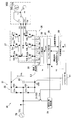
- FIG. 1 is a schematic configuration diagram of a motor drive device according to an embodiment of the present invention.
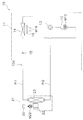
- the schematic block diagram of the motor drive device which concerns on the modification 1G.
- FIG. 1 is a schematic configuration diagram of a motor drive device 30.
- FIG. 1 shows a configuration of an indoor fan motor M22 as an actuator and a motor driving device 30 according to the present embodiment for controlling the driving of the indoor fan motor M22.
- the indoor fan motor M22 is a fan motor used as a drive source of the indoor fan 22 which is one of the devices included in the indoor unit 21 (see FIG. 2) of the air conditioner 10, and is applied with an AC voltage. AC motor to drive.
- the motor drive device 30 is mounted in the indoor unit 21.
- the motor drive device 30 is a device that performs vector control (Field Oriented Control) on the indoor fan motor M22 based on a motor current Im that is a current flowing through the indoor fan motor M22.
- vector control Field Oriented Control
- FIG. 2 is a schematic configuration diagram of the air conditioner 10.
- the air conditioner 10 is a separate type air conditioner mainly having an outdoor unit 11 installed outdoors and an indoor unit 21 installed on an indoor ceiling or wall surface. These units 11 and 21 are connected by refrigerant pipes Pi 1 and Pi 2, and a vapor compression refrigerant circuit 10 a is configured in the air conditioner 10.
- the air conditioner 10 can perform a cooling operation, a heating operation, and the like.
- the air conditioner 10 has a control mode including an operation mode and a stop mode. The operation mode is selected when operating the air conditioner 10. The stop mode is selected when the operation of the air conditioner 10 is stopped.
- Outdoor unit 11 The outdoor unit 11 mainly includes a compressor 12, a four-way switching valve 13, an outdoor heat exchanger 14, an expansion valve 15, and an outdoor fan 16.
- the compressor 12 is a mechanism that sucks low-pressure gas refrigerant and discharges it after compressing it into a high-pressure gas refrigerant.
- a rotary-type compression element such as a rotary type or a scroll type accommodated in a casing (not shown)
- a compressor motor M 12 also accommodated in the casing is used as a drive source.
- the capacity of the compressor 12 can be controlled. That is, the compressor 12 is a compressor whose type can be varied.
- the compressor motor M12 is a three-phase brushless DC motor, and includes a stator and a rotor.
- the four-way switching valve 13 is a valve for switching the direction of the refrigerant flow when switching between the cooling operation and the heating operation.
- the four-way switching valve 13 connects the discharge side of the compressor 12 and the gas side of the outdoor heat exchanger 14 and connects the gas side of the indoor heat exchanger 23 described later and the suction side of the compressor 12.
- the four-way switching valve 13 connects the discharge side of the compressor 12 and the gas side of the indoor heat exchanger 23 and connects the gas side of the outdoor heat exchanger 14 and the suction side of the compressor 12 during heating operation. Connecting. That is, the connection state that the four-way switching valve 13 can take changes according to the operation type of the air conditioner 10.
- the outdoor heat exchanger 14 is a heat exchanger that functions as a refrigerant condenser during the cooling operation and functions as a refrigerant evaporator during the heating operation.
- the outdoor heat exchanger 14 has a liquid side connected to the expansion valve 15 and a gas side connected to the four-way switching valve 13.
- the expansion valve 15 is an electric expansion valve.
- the expansion valve 15 decompresses the high-pressure liquid refrigerant radiated in the outdoor heat exchanger 14 before sending it to the indoor heat exchanger 23 during the cooling operation. Further, during the heating operation, the expansion valve 15 decompresses the high-pressure liquid refrigerant radiated in the indoor heat exchanger 23 before sending it to the outdoor heat exchanger 14.
- the outdoor fan 16 sucks outdoor air into the outdoor unit 11 and supplies it to the outdoor heat exchanger 14, and then discharges the air to the outside of the outdoor unit 11.
- a propeller fan is adopted, and is driven to rotate by using the outdoor fan motor M16 as a drive source.
- the outdoor fan motor M16 is a three-phase brushless motor having a stator and a rotor, for example.
- the outdoor unit 11 includes various units such as a refrigerant pressure sensor, a refrigerant temperature detection sensor, and an outdoor temperature detection sensor, and an outdoor unit control unit (not shown) that controls various devices in the outdoor unit 11. ing.
- the indoor unit 21 mainly has an indoor fan 22 and an indoor heat exchanger 23.
- the indoor fan 22 and the indoor heat exchanger 23 are arranged inside the casing of the indoor unit 21.
- the indoor fan 22 sucks indoor air into the casing through a suction port (not shown), and air after being heat-exchanged by the indoor heat exchanger 23 from the casing through a blower outlet (not shown). It is a blower that blows out indoors.
- the indoor fan 22 is configured by a cross flow fan, for example, and is rotationally driven by using the indoor fan motor M22 as a drive source.
- the indoor fan motor M22 is driven and controlled by the motor driving device 30.
- the indoor fan motor M22 is composed of a three-phase brushless DC motor, and includes a stator 22a and a rotor 22b.
- the stator 22a includes U-phase, V-phase, and W-phase drive coils Lu, Lv, and Lw that are star-connected.
- One ends of the drive coils Lu, Lv, and Lw are connected to drive coil terminals TU, TV, and TW of U-phase, V-phase, and W-phase wirings extending from an inverter 37 (described later), respectively.
- the other ends of the drive coils Lu, Lv, and Lw are connected to each other as a terminal TN.
- These three-phase drive coils Lu, Lv, and Lw generate an induced voltage according to the rotational speed and the position of the rotor 22b as the rotor 22b rotates.
- the rotor 22b includes a plurality of permanent magnets composed of N poles and S poles, and rotates about the rotation axis with respect to the stator 22a.
- the rotational torque of the rotor 22b is transmitted to the indoor fan 22 via an output shaft (not shown) that is on the same axis as the rotational shaft.
- the types of motors are roughly classified into a surface magnet type motor (Surface Permanent Magnet Motor: hereinafter referred to as an SPM motor) and an embedded magnet type motor (Interior Permanent Magnet Motor: hereinafter referred to as an IPM motor).
- SPM motor Surface Permanent Magnet Motor
- IPM motor Interior Permanent Magnet Motor
- the indoor heat exchanger 23 is a heat exchanger that functions as a refrigerant evaporator during cooling operation and functions as a refrigerant condenser during heating operation.
- the indoor heat exchanger 23 is connected to the refrigerant pipes Pi1 and Pi2, and includes, for example, a plurality of fins and a plurality of heat transfer tubes inserted into the fins.
- the indoor heat exchanger 23 performs heat exchange between the indoor air sucked into the casing and the refrigerant flowing through the heat transfer tubes.
- the indoor unit 21 has various sensors such as a horizontal flap provided at the air outlet, an intake air temperature sensor, and an indoor unit controller for controlling various devices in the indoor unit 21. is doing.
- the motor driving device 30 is mounted on, for example, one printed board and is connected to the indoor fan motor M22.
- the motor driving device 30 is supplied with power from a commercial power source 70.
- the motor drive device 30 and the commercial power source 70 are connected by a power cord via, for example, a household outlet.
- the motor drive device 30 mainly includes a DC voltage generation unit 31, a voltage phase detection unit 34, a current detection unit 35, a drive voltage generation unit 36, a level shifter 41, a switching unit 50, and a main body control microcomputer 60. , Is composed of.
- the DC voltage generation unit 31 is connected in series with the commercial power source 70 and converts the AC voltage Vac input from the commercial power source 70 into a DC voltage Vdc.
- the DC voltage generator 31 mainly includes a rectifier 32 and a smoothing capacitor 33.
- the rectifying unit 32 is configured in a bridge shape by four diodes D1a, D1b, D2a, and D2b. Specifically, the diodes D1a and D1b and D2a and D2b are respectively connected in series. The cathode terminals of the diodes D1a and D2a are both connected to the plus side terminal of the smoothing capacitor 33 and function as the positive side output terminal of the rectifying unit 32.
- the anode terminals of the diodes D1b and D2b are connected to the negative terminal of the smoothing capacitor 33 and function as the negative output terminal of the rectifier 32.
- a connection point between the diodes D1a and D1b and a connection point between the diodes D2a and D2b are connected to the commercial power source 70, respectively. That is, the connection point between the diodes D1a and D1b and the connection point between the diodes D2a and D2b each serve as an input to the rectifying unit 32.
- the rectifying unit 32 having such a configuration rectifies an AC voltage Vac input from the commercial power supply 70 via a switch 51 described later, and supplies this to the smoothing capacitor 33.
- the smoothing capacitor 33 has one end connected to the positive output terminal of the rectifying unit 32 and the other end connected to the negative output terminal of the rectifying unit 32.
- the smoothing capacitor 33 smoothes the voltage rectified by the rectifying unit 32.
- the smoothed voltage is a rippled DC voltage Vdc, which is applied to the inverter 37 connected to the subsequent stage of the smoothing capacitor 33, that is, the output side.
- the other end side of the capacitor is a reference potential (hereinafter abbreviated as GND).
- the voltage phase detection unit 34 is electrically connected to the commercial power supply 70 via a switching unit 50 described later. Specifically, the voltage phase detector 34 is connected in parallel with the rectifier 32 between the commercial power supply 70 and the DC voltage generator 31. Moreover, the voltage phase detection part 34 is connected with the below-mentioned sensorless control part 40, and transmits / receives a signal.
- the voltage phase detector 34 detects the phase of the AC voltage Vac by causing the current accompanying the AC voltage Vac to flow inside the voltage phase detector 34. More specifically, the voltage phase detector 34 detects the phase of the AC voltage Vac when the AC voltage Vac supplied from the commercial power supply 70 reaches a predetermined voltage, and a pulse corresponding to the detected phase. A pulse signal having a width is output to the sensorless control unit 40. Since the voltage phase detection unit 34 detects the phase of the AC voltage Vac because the current accompanying the AC voltage Vac flows through the voltage phase detection unit 34, the commercial power supply 70 is connected to the voltage phase detection unit 34. It can also be said to be a “current supply unit” for supplying current to the inside.
- FIG. 3 is a schematic configuration diagram of the voltage phase detector 34.
- the voltage phase detector 34 includes a diode 341, a first resistor 342, a second resistor 343, a photocoupler 344, and a third resistor 345.
- the primary side of the photocoupler 344 is connected to the commercial power supply 70 in parallel with the second resistor 343 via the diode 341 and the first resistor 342.
- the first resistor 342 and the second resistor 343 divide the AC voltage Vac so that the photocoupler 344 is turned on only in a period in which the AC voltage Vac exceeds a reference voltage Vs1 (see FIG. 4) described later.
- the emitter of the output transistor is pulled down by the third resistor 345 and connected to the input port of the sensorless control unit 40, and the collector of the output transistor is pulled up to the control voltage Vcc.
- the configuration of the voltage phase detection unit 34 is merely an example and can be changed as appropriate.
- FIG. 4 is a schematic diagram showing the relationship between the AC voltage Vac and the pulse signal output from the voltage phase detector 34.
- the power supply frequency of the AC voltage Vac is kept constant, and the period T of the AC voltage Vac is constant.
- a reference voltage Vs1 is set as a reference for detecting the phase of the AC voltage Vac.
- the reference voltage Vs1 is set to an appropriate voltage other than 0V.
- the voltage phase detection unit 34 does not turn on the secondary side of the photocoupler 344 and the output level of the pulse signal becomes Low (GND) during the time t1 when the AC voltage Vac is lower than the reference voltage Vs1. It is configured as follows. On the other hand, at time t2 when the AC voltage Vac is higher than the phase detection reference voltage Vs1, the secondary side of the photocoupler 344 is turned on, and the voltage phase detection unit 34 sets High (Vcc) as the output level of the pulse signal. It outputs to the sensorless control part 40. That is, the time t2 is the time from the rising edge to the falling edge of the pulse signal output from the voltage phase detector 34, and corresponds to the pulse width of the pulse signal.
- the pulse width of the output pulse signal is dependent on the magnitude of the AC voltage Vac.
- the pulse signal output from the voltage phase detector 34 becomes Low, and the AC voltage Vac becomes the reference voltage. It may be configured such that the pulse signal output from the voltage phase detector 34 becomes High when it becomes lower than Vs1 (that is, time t1).
- the reference voltage Vs1 may be set to a negative voltage instead of a positive voltage.
- the current detection unit 35 is connected between the smoothing capacitor 33 and the inverter 37 in the drive voltage generation unit 36 and connected to the negative output terminal side of the smoothing capacitor 33.
- the current detection unit 35 detects the motor current Im flowing through the indoor fan motor M22 after the indoor fan motor M22 is activated.
- Such a current detection unit 35 is configured by, for example, a shunt resistor and an amplifier circuit (not shown).
- the shunt resistor is connected in series on the GND wiring L1 connected to the negative output terminal of the smoothing capacitor 33.
- the amplifier circuit is a circuit composed of an operational amplifier or the like for amplifying the voltage across the shunt resistor at a predetermined magnification. Two inputs are connected to both ends of the shunt resistor, and one output is the sensorless control unit 40. It is connected to the.
- the current detection unit 35 detects the voltage across the shunt resistor according to the motor current Im according to the energization state. The motor current Im can be detected.
- the drive voltage generator 36 detects the drive voltages SU, SV, and SW (corresponding to drive signals) that are three-phase AC voltages for driving the indoor fan motor M22, and the detection results of the voltage phase detector 34 and the current detector 35. And so on.
- the drive voltage generator 36 outputs the generated drive voltages SU, SV, and SW to the indoor fan motor M22.
- the drive voltage generation unit 36 according to the present embodiment generates the drive voltages SU, SV, and SW based on the rotor position sensorless method using the estimated value of the DC voltage Vdc obtained from the detected voltage phase.
- the drive voltage generation unit 36 includes an inverter 37 (corresponding to an output unit) and an indoor fan control unit 38 (corresponding to a determination unit).
- the inverter 37 is connected to the output side of the smoothing capacitor 33.
- the inverter 37 includes a plurality of insulated gate bipolar transistors (hereinafter simply referred to as transistors) Q3a, Q3b, Q4a, Q4b, Q5a, Q5b and a plurality of freewheeling diodes D3a, D3b, D4a, D4b, D5a and D5b are included.
- Transistors Q3a and Q3b, Q4a and Q4b, and Q5a and Q5b are connected to each other in series.
- Each of the diodes D3a to D5b is connected in reverse parallel to each of the transistors Q3a to Q5b by connecting the collector terminal of the transistor and the cathode terminal of the diode and connecting the emitter terminal of the transistor and the anode terminal of the diode. It is connected.
- the inverter 37 turns on and off each of the transistors Q3a to Q5b at a timing instructed by a gate drive unit 39 (described later), so that the drive voltages SU, SV, and SW (corresponding to the drive signal) having a desired duty ) Is generated.
- the drive voltages SU, SV, and SW are output to the indoor fan motor M22 from the connection points NU, NV, NW of the transistors Q3a and Q3b, Q4a and Q4b, and Q5a and Q5b. That is, the inverter 37 supplies power to the indoor fan motor M22.
- the indoor fan control unit 38 is a microcomputer including a RAM, a ROM, and a CPU, and is connected to the inverter 37.
- the indoor fan control unit 38 is a drive control computer dedicated to the indoor fan motor M22.
- the indoor fan control unit 38 performs control to determine the drive voltages SU, SV, and SW that the inverter 37 should output to the indoor fan motor M22 using a pulse signal or the like output from the voltage phase detection unit 34.
- Such an indoor fan control unit 38 mainly includes a gate drive unit 39 and a sensorless control unit 40 as shown in FIG.
- Gate driver 39 Based on the voltage command value Vpwm from the sensorless control unit 40, the gate drive unit 39 changes the on / off states of the transistors Q3a to Q5b of the inverter 37. Specifically, the gate drive unit 39 is configured so that the drive voltages SU, SV, and SW having the duty determined by the sensorless control unit 40 are output from the inverter 37 to the indoor fan motor M22. Gate control voltages Gu, Gx, Gv, Gy, Gw and Gz to be applied to the gate are generated. The generated gate control voltages Gu, Gx, Gv, Gy, Gw and Gz are applied to the gate terminals of the respective transistors Q3a to Q5b.
- the voltage command value Vpwm is a command value for determining parameters relating to the drive voltages SU, SV and SW.
- the voltage command value Vpwm is determined in association with the value of the motor current Im detected by the current detection unit 35 and the estimated value of the DC voltage Vdc estimated by the sensorless control unit 40, and is output from the sensorless control unit 40.
- the parameters relating to the drive voltages SU, SV, and SW include the duty, frequency, voltage value, and the like of each of the drive voltages SU, SV, and SW.
- the voltage command value Vpwm is the drive voltage SU, SV, and SW.
- the case where the indoor fan motor M22 is PWM-controlled is taken as an example.
- the sensorless control unit 40 is connected to the voltage phase detection unit 34, the current detection unit 35, the gate drive unit 39, and the main body control microcomputer 60.
- the sensorless control unit 40 is a functional unit for driving and controlling the indoor fan motor M22 by a sensorless method (more specifically, a rotor position sensorless method).
- the indoor fan motor M22 is first activated by a DC excitation method or a forced drive method.
- direct current is applied to the indoor fan motor M22 immediately before start-up, so that the position of the rotor 22b in the indoor fan motor M22 is temporarily fixed at a predetermined position, and the indoor fan motor is fixed from the state where the rotor 22b is fixed.
- the driving of M22 is started.
- the indoor fan motor M22 is forcibly energized by applying drive voltages SU, SV and SW having a certain voltage value and frequency to the indoor fan motor M22 regardless of the position of the rotor 22b. This is a method for forcibly starting.
- the sensorless control unit 40 estimates the position of the rotor 22b of the indoor fan motor M22 after startup, and estimates the rotational speed of the indoor fan motor M22 based on the estimated position of the rotor 22b.
- the estimated rotation speed of the indoor fan motor M22 is input to the main body control microcomputer 60 as a rotation speed signal FG.
- the sensorless control unit 40 receives the operation command, the estimated position of the rotor 22b, the estimated rotation speed, and the estimated DC voltage Vdc.
- the duty of the drive voltages SU, SV, and SW at each control timing is determined as the voltage command value Vpwm by the rotor position sensorless method using the voltage value and the detection result of the current detection unit 35.
- the voltage value of the DC voltage Vdc is estimated based on the pulse signal output from the voltage phase detector 34.
- the sensorless control unit 40 holds in advance a table in which the correspondence relationship between the pulse width of the pulse signal output from the voltage phase detection unit 34 and the voltage value of the DC voltage Vdc is defined and output.
- the voltage value of the DC voltage Vdc is estimated by referring to the table according to the pulse width.
- FIG. 4 shows an example of the estimated DC voltage Vdc.
- the DC voltage Vdc has a ripple synchronized with the power supply voltage at a frequency twice the power supply voltage, and changes depending on the capacity of the capacitor and the load (current).
- the DC voltage Vdc changes according to the magnitude of the load (current)
- the rotor position sensorless system relates to various parameters indicating the characteristics of the indoor fan motor M22, the voltage value of the DC voltage Vdc, the motor current Im (that is, the detection result of the current detection unit 35), and the control of the indoor fan motor M22.
- This is a method of performing estimation of the position of the rotor 22b, estimation of the rotational speed, PI control with respect to the rotational speed, PI control with respect to the motor current Im, etc. using a predetermined mathematical model or the like.
- Various parameters indicating the characteristics of the indoor fan motor M22 include winding resistance, inductance component, induced voltage, number of poles and the like of the indoor fan motor M22 used.
- Level shifter 41 As shown in FIG. 1, the level shifter 41 is connected in parallel to the smoothing capacitor 33, and a voltage across the smoothing capacitor 33 (that is, a DC voltage Vdc) is applied.
- the output of the level shifter 41 is connected to the indoor fan control unit 38, the main body control microcomputer 60, and the driving power supply unit 52.
- the level shifter 41 converts the applied DC voltage Vdc into three predetermined voltages V1, V2, and V3.
- the level shifter 41 applies the converted predetermined voltages V1, V2, and V3 to the indoor fan control unit 38, the drive power supply unit 52, and the main body control microcomputer 60 as power supply voltages. That is, the level shifter 41 functions as a power source for the indoor fan control unit 38, the drive power supply unit 52, and the main body control microcomputer 60.
- the level shifter 41 converts the DC voltage Vdc into a voltage V1 of 3V and voltages V2 and V3 of 5V.
- the voltage V1 of 3V is a power supply voltage applied to the main body control microcomputer 60.
- the voltage V2 or V3 of 5V is a power supply voltage applied to the indoor fan control unit 38 or the driving power supply unit 52.
- the level shifter 41 may further convert a control power supply voltage (for example, 15 V) for controlling the inverter 37 as described above.
- the switching unit 50 is for switching the current flow to the voltage phase detection unit 34 and is connected in series with the voltage phase detection unit 34 between the commercial power supply 70 and the voltage phase detection unit 34 as described above. ing. By providing the switching unit 50 in this way, the motor drive device 30 can cut off the power supply to the voltage phase detection unit 34.
- the switching unit 50 mainly includes a switch 51 and a driving power supply unit 52.
- the switch 51 is an electrical component for preventing the power from being consumed unnecessarily in the voltage phase detection unit 34 configured such that a current flows if the voltage Vac is applied.
- the switch 51 is configured by, for example, a MOSFET (Metal-Oxide-Semiconductor Field-Effect Transistor) which is a kind of semiconductor switch, and plays a role of a switch for switching whether or not current flows to the voltage phase detection unit 34. Yes.
- MOSFET Metal-Oxide-Semiconductor Field-Effect Transistor
- the MOSFET is turned on by setting the potential of the gate terminal to a threshold value or higher with respect to the potential of the source terminal. Therefore, by applying an appropriate voltage to the gate terminal, the switch 51 formed of a MOSFET can operate as a switch for switching on and off.
- Driving power supply unit 52 includes a plurality of transistors and the like.
- the input of the drive power supply unit 52 is connected to the main body control microcomputer 60 and the level shifter 41.
- the output of the driving power supply unit 52 is connected to the gate terminal of the switch 51.
- the driving power supply unit 52 is supplied with a predetermined power supply voltage V3 from the level shifter 41.
- the drive power supply unit 52 generates a switch drive power supply Vsw for the switch 51 in response to an instruction from the main body control microcomputer 60, and outputs this to the drive power supply unit 52. That is, the operation of turning on and off the switch 51 is controlled by the main body control microcomputer 60.
- the drive power supply unit 52 turns on the switch 51 by supplying a switch drive power supply Vsw of, for example, 5 V to the switch 51 so that a current flows through the voltage phase detection unit 34. Further, the drive power supply unit 52 turns off the switch 51 by cutting off the supply of the switch drive power supply Vsw to the switch 51 so that no current flows through the voltage phase detection unit 34.
- the main body control microcomputer 60 is a microcomputer including a RAM, a ROM, and a CPU.
- the main body control microcomputer 60 is supplied with the power supply voltage V ⁇ b> 1 from the level shifter 41.
- the main body control microcomputer 60 is connected to a remote controller, an indoor unit control unit, an outdoor unit control unit, and the like, although not shown, in addition to the indoor fan control unit 38.
- the main body control microcomputer 60 comprehensively controls a plurality of devices included in the air conditioner 10 (specifically, the compressor 12, the four-way switching valve 13, the outdoor fan 16, the indoor fan 22, and the like). For example, when an operation start instruction is given from the remote controller, the main body control microcomputer 60 outputs an activation instruction for the compressor motor M12 and the outdoor fan motor M16 as an operation start instruction to the outdoor unit control unit.
- the main body control microcomputer 60 outputs an instruction to start the indoor fan motor M22 to the indoor unit controller when an instruction to start operation is given from the remote controller. Further, the main body control microcomputer 60 monitors a rotation speed signal FG indicating the rotation speed of the indoor fan motor M22, or outputs an operation command including the rotation speed command Vfg to the sensorless control unit 40.
- the main body control microcomputer 60 controls the switching unit 50 by causing the drive power supply unit 52 to supply and shut off the switch drive power supply Vsw to the switch 51.
- the main body control microcomputer 60 performs control so that the switch 51 is turned on in the operation mode in which the indoor fan motor M22 is driven. Thereby, a current flows through the voltage phase detector 34 in the operation mode.
- the main body control microcomputer 60 controls the switch 51 to be turned off in the stop mode when the indoor fan motor M22 is not driven. As a result, no current flows through the voltage phase detector 34.
- the main body control microcomputer 60 switches the switch 51 on or off depending on whether the operation mode or the stop mode. Thereby, it is suppressed that a current flows into the voltage phase detection unit 34 in the stop mode, and the power consumption of the motor drive device 30 is 0.02 W compared with the case where the current flows in the voltage phase detection unit 34 in the stop mode. It is reduced by about 0.24W. Note that the power consumption reduction value varies depending on the product design specifications and installation environment.
- FIG. 5 shows the modes that the air conditioner 10 can take, the power supply voltage V2 applied to the indoor fan control unit 38 and the power supply voltage V3 applied to the driving power supply unit 52, the driving state of the indoor fan motor M22, the switch 51 It is a timing chart showing how the state which can be taken and operation
- the air conditioner 10 is operating. Specifically, focusing on the indoor fan motor M22, in the “operation mode”, the power supply voltage V2 of 5 V is applied to the indoor fan control unit 38, and the indoor fan control unit 38 is connected to the indoor fan motor M22. The drive is being controlled. For this reason, the indoor fan motor M22 is driven.
- the drive power supply unit 52 supplies the switch drive power supply Vsw to the switch 51.
- the switch 51 is turned on, and a power supply voltage is supplied from the commercial power supply 70 to the voltage phase detector 34 via the switch 51, and a current flows inside the voltage phase detector 34.
- the voltage phase detector 34 can detect the phase of the AC voltage Vac necessary for the drive control of the indoor fan motor M22.
- “Stop mode” has “standby determination mode” and “standby mode” as further detailed modes, but “standby” until a predetermined time elapses after the operation stop instruction is given. "Judgment mode" is assigned.
- “Standby determination mode” is a mode for determining whether or not to shift to “standby mode”.
- the standby mode for example, the supply of the power supply voltage V2 or V3 from the level shifter 41 to the indoor fan control unit 38 and the drive power supply unit 52 is cut off, so that various types of air conditioners 10 are possible.
- the operation of the equipment is stopped.
- the air conditioner 10 is set in a state in which only a minimum number of devices are started up (standby state) so that various devices can be started immediately when the next operation instruction is received. This mode saves as much energy as possible.
- the main body control microcomputer 60 determines whether to shift from the “standby determination mode” to the “standby mode”.
- the drive of the indoor fan motor M22 is stopped first, and the indoor unit 21 Operation is stopped.
- the main body control microcomputer 60 performs control to switch the switch 51 from on to off at a timing when a transition from the “standby determination mode” to the “standby mode” has occurred after a predetermined time has elapsed from the operation stop instruction.
- the level shifter 41 is controlled so as to cut off the supply of the power supply voltage V2 or V3 to the indoor fan control section 38 and the drive power supply section 52.
- the indoor fan control unit 38 stops the control operation of the indoor fan motor M22. Further, the power supply voltage V3 to the driving power supply unit 52 is cut off, whereby the switch 51 is switched from on to off. Therefore, the current path from the commercial power supply 70 to the voltage phase detector 34 is interrupted, and no current flows inside the voltage phase detector 34. Therefore, the voltage phase detector 34 is in a state where it cannot detect the value of the AC voltage Vac.
- the voltage phase detector 34 can detect the phase of the power supply voltage (that is, the AC voltage Vac) supplied from the commercial power supply 70.
- the determination of mode transition is made by the main body control microcomputer 60, and thus it is necessary to continue to supply the power supply voltage to the main body control microcomputer 60. In other words, it is necessary to supply the power supply voltage V1 to the main body control microcomputer 60 even in the “standby mode”. Accordingly, the level shifter 41 and the DC voltage generation unit 31 that is the conversion source of the level shifter 41 need to continue to operate even in at least the portion related to the supply of the power supply voltage V1 even during the “standby mode”.
- the main body controlling microcomputer 60 is in the standby mode in which the current flows into the voltage phase detector 34 in the operation mode in which the indoor fan motor M22 that is an actuator is driven, and the indoor fan motor M22 stops driving.
- the switching unit 50 is switched so that no current flows into the voltage phase detection unit 34. Thereby, a current flows into the voltage phase detector 34 in the operation mode, and a current does not flow into the voltage phase detector 34 in the standby mode. As a result, the power consumption of the voltage phase detector 34 in the standby mode is reduced. Therefore, the power consumption of the air conditioner 10 can be reduced.
- the main body control microcomputer 60 detects the voltage phase in the indoor fan control unit 38 that uses the detection result of the voltage phase detection unit 34 when the detection result of the voltage phase detection unit 34 is necessary.
- the switching unit 50 is switched so that current does not flow into the voltage phase detection unit 34 in the standby mode when the current flows into the unit 34 and the detection result of the voltage phase detection unit 34 is unnecessary.
- the indoor fan control unit 38 when the detection result of the voltage phase detection unit 34 is required, the current flows into the voltage phase detection unit 34 in the operation mode, and the detection result of the voltage phase detection unit 34 is unnecessary.
- the standby mode current does not flow into the voltage phase detector 34.
- the power consumption of the voltage phase detector 34 in the standby mode which is a time when the detection result of the voltage phase detector 34 is unnecessary, is reduced. Therefore, the power consumption of the air conditioner 10 can be reduced.
- the main body control microcomputer 60 shifts to the standby mode when a predetermined time has elapsed after the indoor fan motor M22 that is an actuator stops driving, and the current flows into the voltage phase detector 34.
- the switching unit 50 is switched so as to shut off.
- the flow of current into the voltage phase detector 34 is interrupted when it may be reliably interrupted.
- stable control of the switching unit 50 can be realized.
- the actuator is the indoor fan motor M22 that is at least one drive source of a plurality of devices included in the air conditioner 10. Thereby, the power consumption of the air conditioner 10 can be reduced.
- the voltage phase detector 34 detects the phase of the AC voltage Vac supplied from the commercial power supply 70. Thereby, in the air conditioner 10 that controls the indoor fan motor M22 that is an actuator based on the detected phase of the AC voltage Vac, the power consumption in the standby mode when the phase of the AC voltage Vac is not required is reduced. Has been reduced.
- the motor to be driven by the motor drive device 30 may be other types of motors such as an induction motor driven by an inverter instead of a brushless DC motor.
- the voltage phase detector 34 is configured to be connected to the commercial power source 70 via the switch 51 and supplied with power.
- the voltage phase detection unit 34 may be configured to be connected to a power source that is not a commercial power source via the switch 51 to be supplied with power.
- the voltage phase detection unit 34 detects the phase of the AC voltage Vac supplied from the commercial power supply 70, and the sensorless control unit 40 estimates the value of the DC voltage Vdc based on the detection result.
- the voltage phase detector 34 may identify the polarity by detecting the zero cross point of the AC voltage Vac.
- the voltage phase detector 34 may be configured to detect a change in polarity of the AC voltage Vac and output a pulse signal based on the change in polarity.
- the voltage phase detector 34 outputs a pulse signal at a time t3 corresponding to a period in which the polarity of the AC voltage Vac is positive, and corresponds to a period in which the polarity of the AC voltage Vac is negative.
- generation and output of the pulse signal may not be performed.
- the time t3 is the time from the rising edge to the falling edge of the pulse signal output from the voltage phase detector 34, and corresponds to the pulse width of the pulse signal.
- the sensorless control unit 40 refers to the table in which the correspondence relationship between the pulse width of the pulse signal output from the voltage phase detection unit 34 and the voltage value of the DC voltage Vdc is defined, whereby the voltage value of the DC voltage Vdc is determined. May be configured to estimate.
- the pulse signal output from the voltage phase detector 34 may be configured to be Low output at time t3 and to be High output at time t4.
- the power consumption of the voltage phase detector 34 when the polarity of the AC voltage Vac or the detection of the zero-cross point is not required is reduced, and the power consumption of the air conditioner 10 can be reduced.
- the voltage phase detector 34 is connected in parallel with the rectifier 32 between the commercial power supply 70 and the DC voltage generator 31.
- the present invention is not limited to this.
- the DC voltage generator 31 and the inverter 37 may be connected in parallel with the smoothing capacitor 33. In such a case, the effect similar to that of the above embodiment can be realized by connecting the switching unit 50 in series with the voltage phase detection unit 34 as in the above embodiment.
- the voltage phase detector 34 detects the phase of the DC voltage Vdc and outputs a pulse signal.
- the voltage phase detector 34 is set with a reference voltage Vs2 as a reference for detecting the phase of the DC voltage Vdc.
- the reference voltage Vs2 is set to an appropriate voltage exceeding 0V.
- the voltage phase detector 34 does not generate and output a pulse signal at time t5, which is a period in which the DC voltage Vdc is lower than the reference voltage Vs2.
- the voltage phase detection unit 34 generates a pulse signal and outputs it to the sensorless control unit 40. That is, the time t6 is the time from the rising edge to the falling edge of the pulse signal output from the voltage phase detector 34, and corresponds to the pulse width of the pulse signal.
- the pulse width of the output pulse signal depends on the magnitude of the DC voltage Vdc.
- the pulse signal output from the voltage phase detector 34 may be configured to be Low output at time t6 and to be High output at time t5.
- the switching unit 50 includes the switch 51 and the driving power supply unit 52 has been described as illustrated in FIG. 1.
- the switching unit 50 may include only the switch 51 without including the driving power supply unit 52.
- the switch 51 is turned on and off by connecting the gate terminal of the switch 51 and the main body control microcomputer 60 and applying a switch control signal sent from the main body control microcomputer 60 as the switch driving power source Vsw. May be switched.
- the switch 51 is not turned on or off in response to the supply or cutoff of the switch drive power supply Vsw, but is sent from the main body control microcomputer 60.
- the switch 51 may be configured to be turned on or off according to the state of the switch control signal.
- the switch 51 is configured by a MOSFET.
- the configuration of the switch 51 according to the present invention is not limited to the MOSFET.
- the switch 51 may be another semiconductor switch such as an IGBT (Insulated Gate Bipolar Transistor) or a solid state relay, or an electromagnetic relay.
- the mode is changed from the “standby mode” to the “operation mode” and the switch 51 is switched from OFF to ON at the timing when the operation instruction is given.
- the mode is changed from “standby mode” to “operation mode” and the switch 51 is switched from OFF to ON. Also good.
- the power consumption reduction device according to the present invention is applied to the motor drive device 30 that is an actuator drive device, but can also be applied to a device that is not an actuator drive device.
- the present invention can also be applied to a DC power supply device 80 that constantly detects the phase of the power supply voltage supplied from the commercial power supply 70 and constantly consumes power.
- the DC power supply device 80 shown in FIG. 10 will be described.
- the DC power supply device 80 is a device that converts the AC voltage Vac supplied from the commercial power supply 70 into a DC voltage Vdc.
- the DC power supply device 80 mainly includes a reactor 81, a power factor correction switch 82, a DC voltage generation unit 83, a voltage phase detection unit 84, a power factor improvement switch control unit 85, a level shifter 86, and a switching control unit 87. And a switching unit 88, and is electrically connected to the commercial power source 70 and the load 90.
- the load 90 is assumed to be an inverter circuit, a motor, or the like, but is not limited to this, and can be appropriately selected.
- the DC voltage generation unit 83 includes a rectification unit 83a and a smoothing capacitor 83b. Since these components have the same configuration as the DC voltage generation unit 31, a description thereof will be omitted. Moreover, since the voltage phase detection part 84 is the structure similar to the voltage phase detection part 34, description is abbreviate
- the switching unit 88 mainly includes a switch 88a and a driving power supply unit 88b. Since these are the same as the switching unit 50, the description thereof is omitted.
- the reactor 81 is disposed between the commercial power supply 70 and the AC input terminal of the DC voltage generator 83.
- the power factor correction switch 82 is a switch for short-circuiting the commercial power supply 70, and is represented by one element in FIG. 10, but actually, for example, a diode bridge or a MOSFET It is configured by combining semiconductor elements such as IGBTs.
- the DC voltage generation unit 83 rectifies the current that flows due to the AC voltage Vac of the commercial power supply 70 and the short-circuiting / opening operation of the power factor correction switch 82 and supplies it to the load 90.
- the voltage phase detector 84 is connected to both ends of the commercial power supply 70 via the switch 88a, and is arranged in parallel with the power factor correction switch 82 between the commercial power supply 70 and the reactor 81.
- the voltage phase detector 84 is connected to the input port of the power factor correction switch controller 85, which is a microcomputer, and detects the zero cross point of the AC voltage Vac by the method shown in FIG.
- the pulse signal is output to the power factor correction switch control unit 85.
- the power factor correction switch control unit 85 corrects the timing of the pulse signal output from the voltage phase detection unit 84, and then generates a drive signal for driving the power factor correction switch 82, for example, a power supply half cycle.
- the power factor correction switch 82 is repeatedly shorted and opened once every time.
- the power factor correction switch control unit 85 controls the power factor correction switch 82 so as to short-circuit after a predetermined time from the zero cross point and then open after a predetermined time. That is, the direct-current power supply 80 determines the power factor variation according to the pulse width of the pulse signal output from the voltage phase detector 84 as the main variation factor in detecting the voltage phase of the alternating-current power supply. By correcting the timing at which the improvement switch 82 is short-circuited / opened, variations in power factor are suppressed.
- the level shifter 86 is connected in parallel to the smoothing capacitor 83b, and a voltage across the smoothing capacitor 83b (that is, a DC voltage Vdc) is applied.
- the output of the level shifter 86 is connected to the power factor correction switch control unit 85, the driving power supply unit 88b, and the switching control unit 87.
- Such a level shifter 86 converts the applied DC voltage Vdc into three predetermined voltages V4, V5 and V6.
- the level shifter 86 applies the converted predetermined voltages V4, V5, and V6 as power supply voltages to the power factor correction switch control unit 85, the switching control unit 87, and the drive power supply unit 88b, respectively.
- the level shifter 86 functions as a power source for the power factor correction switch control unit 85, the drive power supply unit 88b, and the switching control unit 87.
- the level shifter 86 converts the DC voltage Vdc into 3V voltages V4 and V6 and 5V voltage V5.
- the voltage V4 or V5 of 3 V is a power supply voltage applied to the power factor correction switch control unit 85 or the switching control unit 87.
- the 5V voltage V6 is a power supply voltage applied to the driving power supply unit 88b.
- the switching control unit 87 is a microcomputer including a RAM, a ROM, and a CPU.
- the switching control unit 87 is supplied with the power supply voltage V5 from the level shifter 86.
- the switching control unit 87 is connected to a remote controller (not shown). Further, the switching control unit 87 receives the instruction from the user via the remote controller, and causes the driving power supply unit 88b to supply and shut off the switch driving power source Vsw1 ′ to the switch 88a, thereby switching the switching unit. 88 controls are performed.
- the switching unit 88 is connected in series with the voltage phase detection unit 84. By providing the switching unit 88 in this way, the DC power supply device 80 can block the flow of current to the voltage phase detection unit 84.
- the input of the drive power supply unit 88 b is connected to the switching control unit 87 and the level shifter 86.
- the output of the driving power supply unit 88b is connected to the gate terminal of the switch 88a.
- the driving power supply unit 88b is supplied with a predetermined voltage V6 from the level shifter 86.
- the drive power supply unit 88b generates a switch drive power supply Vsw1 ′ for the switch 88a in response to an instruction from the switching control unit 87, and outputs this to the drive power supply unit 88b. That is, the operation of turning on and off the switch 88a is controlled by the switching control unit 87.
- the drive power supply unit 88b supplies the switch drive power supply Vsw1 ′ of 5V, for example, to the switch 88a to turn on the switch 88a, and the current flows through the voltage phase detection unit 84. Further, the drive power supply unit 88b cuts off the supply of the switch drive power supply Vsw1 ′ to the switch 88a, thereby turning off the switch 88a so that no current flows through the voltage phase detection unit 84.
- the power factor correction switch control unit 85 controls on / off of the power factor correction switch 82 based on the output from the voltage phase detection unit 84.
- the power factor correction switch control unit 85 uses the detection result of the voltage phase detection unit 84.
- the control by the power factor correction switch control unit 85 is executed when the load 90 is operating. Therefore, when the load 90 is operating, the detection result of the voltage phase detector 84 is necessary, and the switching controller 87 controls the switching unit 88 so that the switch 88a is turned on.
- the control by the power factor correction switch control unit 85 is not executed when the load 90 stops operating. Therefore, when the load 90 stops operating, the detection result of the voltage phase detector 84 is unnecessary, and the switching controller 87 controls the switching unit 88 so that the switch 88a is turned off.
- the switching control unit 87 uses the detection result of the voltage phase detection unit 84 to cause a current to flow into the voltage phase detection unit 84 when the detection result is necessary in the power factor correction switch control unit 85.
- the switching unit 88 is switched so that no current flows into the voltage phase detection unit 84.
- the detection result of the voltage phase detection unit 84 is necessary, current flows into the voltage phase detection unit 84, and when the detection result of the voltage phase detection unit 84 is unnecessary, no current flows into the voltage phase detection unit 84. It has become.
- power consumption when the detection result of the voltage phase detector 84 is unnecessary is reduced. Therefore, the power consumption of the DC power supply device 80 can be reduced.
- the power supply frequency can be detected from the pulse width of the pulse signal, it is possible to perform control using the power supply frequency or to count the timer.
- the present invention can be used for, for example, an actuator driving device or a DC power supply device in an air conditioner.
Landscapes
- Engineering & Computer Science (AREA)
- Power Engineering (AREA)
- Control Of Motors That Do Not Use Commutators (AREA)
- Inverter Devices (AREA)
- Control Of Ac Motors In General (AREA)
- Air Conditioning Control Device (AREA)
Abstract
モータ駆動装置(30)の電圧位相検出部(34)は、商用電源(70)と電気的に接続され、内部に電流が流れることにより商用電源(70)から供給される電圧の特性を検出する。駆動電圧生成部(36)は、電圧位相検出部(34)の検出結果に基づいて、室内ファンモータ(M22)を駆動するための駆動信号を生成する。スイッチ(51)は、商用電源(70)と電圧位相検出部(34)との間において電圧位相検出部(34)に直列に接続され、電圧位相検出部(34)内への電流の流れを遮断可能である。本体制御用マイコン(60)は、室内ファンモータ(M22)が駆動する運転モード時には電圧位相検出部(34)内へ電流が流れ、室内ファンモータ(M22)が駆動を停止している待機モード時には電圧位相検出部(34)内へ電流が流れないように、切換部(50)を制御する。
Description
本発明は、消費電力を削減する装置に関する。
従来、モータなどの負荷をインバータにより駆動する装置などにおいては、供給される電圧の、位相、ゼロクロス点および極性などのいわゆる電圧特性情報を検出し、その検出結果に応じて制御等をおこなうものが知られている。例えば、特許文献1(特開2012-125018号公報)では、交流電源から出力される交流電圧を直流電圧に変換する際に、電圧極性検出部によって交流電圧の極性を検出し、その検出結果に応じてスイッチを切り換えてノイズを抑制する直流電圧変換装置が開示されている。
ところで、上述のような装置においては、交流電源から装置に対して常時電流が供給されており、常時電力を消費しているものがある。例えば、特許文献1に記載される直流電圧変換装置においては、負荷が動作状態にない場合においても、電圧極性検出部に電流が流れて電力を消費することが想定される。かかる場合には、消費電力の増大が懸念される。
そこで、本発明の課題は、消費電力を削減できる装置を提供することである。
本発明の第1観点に係る消費電力削減装置は、電圧特性検出部と、駆動信号生成部と、スイッチ部と、スイッチ制御部と、を備える。電圧特性検出部は、電源と電気的に接続され、内部に電流が流れることにより電源から供給される電圧の特性を検出する。駆動信号生成部は、電圧特性検出部の検出結果に基づいて、アクチュエータを駆動するための駆動信号を生成する。スイッチ部は、電源と電圧特性検出部との間において電圧特性検出部に直列に接続され、電圧特性検出部内への電流の流れを遮断可能である。スイッチ制御部は、スイッチ部の切換えを制御する。スイッチ制御部は、アクチュエータが駆動する運転モード時には電圧特性検出部内へ電流が流れ、アクチュエータが駆動を停止している待機モード時には電圧特性検出部内へ電流が流れないように、スイッチ部を切り換える。
本発明の第1観点に係る消費電力削減装置では、スイッチ制御部は、アクチュエータが駆動する運転モード時には電圧特性検出部内へ電流が流れ、アクチュエータが駆動を停止している待機モード時には電圧特性検出部内へ電流が流れないように、スイッチ部を切り換える。これにより、運転モード時には電圧特性検出部内へ電流が流れ、待機モード時には電圧特性検出部内へ電流が流れなくなる。その結果、待機モード時における電圧特性検出部の消費電力が削減される。したがって、消費電力を削減できる。
本発明の第2観点に係る消費電力削減装置は、電圧特性検出部と、検出結果利用部と、スイッチ部と、スイッチ制御部と、を備える。電圧特性検出部は、電源と電気的に接続され、内部に電流が流れることにより電源から供給される電圧の特性を検出する。検出結果利用部は、電圧特性検出部の検出結果に基づいて動作する。スイッチ部は、電源と電圧特性検出部との間において電圧特性検出部に直列に接続され、電圧特性検出部内への電流の流れを遮断可能である。スイッチ制御部は、スイッチ部の切換えを制御する。スイッチ制御部は、検出結果利用部において電圧特性検出結果が必要な時には電圧特性検出部内へ電流が流れ、検出結果利用部において電圧特性検出結果が不要な時には電圧特性検出部内へ電流が流れないようにスイッチ部を切り換える。
本発明の第2観点に係る消費電力削減装置では、スイッチ制御部は、検出結果利用部において電圧特性検出結果が必要な時には電圧特性検出部内へ電流が流れ、検出結果利用部において電圧特性検出結果が不要な時には電圧特性検出部内へ電流が流れないようにスイッチ部を切り換える。これにより、電圧特性検出結果が必要な時には電圧特性検出部内へ電流が流れ、電圧特性検出結果が不要な時には電圧特性検出部内へ電流が流れなくなる。その結果、電圧特性検出結果が不要な時における電圧特性検出部の消費電力が削減される。したがって、消費電力を削減できる。
本発明の第3観点に係る消費電力削減装置は、第1観点に係る消費電力削減装置であって、スイッチ制御部は、アクチュエータが駆動を停止してから所定時間が経過した時に電圧特性検出部内への電流の流れを遮断するように、スイッチ部を切り換える。
本発明の第3観点に係る消費電力削減装置では、スイッチ制御部は、アクチュエータが駆動を停止してから所定時間が経過した時に電圧特性検出部内への電流の流れを遮断するように、スイッチ部を切り換える。これにより、電圧特性検出部内への電流の流れが、確実に遮断されてもよい場合に遮断される。その結果、安定したスイッチ部の切換制御を実現できる。
本発明の第4観点に係る消費電力削減装置は、第1観点または第3観点に係る消費電力削減装置であって、アクチュエータは、空調機に含まれている複数の機器の、少なくとも1つの駆動源であるモータである。駆動信号生成部は、決定部と、出力部と、を含む。決定部は、電圧特性検出部の検出結果を用いて駆動信号を決定する制御を行う。出力部は、決定部により決定された駆動信号を生成してアクチュエータに出力する。また、統括制御部をさらに備える。統括制御部は、空調機に含まれている複数の機器を統括的に制御する。統括制御部は、スイッチ制御部を含む。
本発明の第4観点に係る消費電力削減装置では、アクチュエータは、空調機に含まれている複数の機器の、少なくとも1つの駆動源であるモータである。これにより、空調機の消費電力を削減することができる。
本発明の第5観点に係る消費電力削減装置は、第1観点から第4観点のいずれかに係る消費電力削減装置であって、電圧特性検出部は、電源から供給される電圧の位相を検出する。
本発明の第5観点に係る消費電力削減装置では、電圧特性検出部は、電源から供給される電圧の位相を検出する。これにより、電源電圧の位相の検出が不要な時における電圧特性検出部の消費電力が削減される。
本発明の第6観点に係る消費電力削減装置は、第1観点から第4観点のいずれかに係る消費電力削減装置であって、電圧特性検出部は、電源から供給される電圧の極性を検出する。
本発明の第6観点に係る消費電力削減装置では、電圧特性検出部は、電源から供給される電圧の極性を検出する。これにより、電源電圧の極性の検出が不要な時における電圧特性検出部の消費電力が削減される。
本発明の第7観点に係る消費電力削減装置は、第1観点から第4観点のいずれかに係る消費電力削減装置であって、電圧特性検出部は、電源から供給される電圧のゼロクロス点を検出する。
本発明の第7観点に係る消費電力削減装置では、電圧特性検出部は、電源から供給される電圧のゼロクロス点を検出する。これにより、電源電圧のゼロクロス点の検出が不要な時における電圧特性検出部の消費電力が削減される。
本発明の第1観点に係る消費電力削減装置では、待機モード時における電圧特性検出部の消費電力が削減される。したがって、消費電力を削減できる。
本発明の第2観点に係る消費電力削減装置では、電圧特性の検出が不要な時における電圧特性検出部の消費電力が削減される。したがって、消費電力を削減できる。
本発明の第3観点に係る消費電力削減装置では、安定したスイッチ部の切換制御を実現できる。
本発明の第4観点に係る消費電力削減装置では、空調機においてモータの駆動が停止している待機モード時の消費電力を削減することができる。
本発明の第5観点に係る消費電力削減装置では、電圧位相の検出が不要な時における電圧特性検出部の消費電力が削減される。
本発明の第6観点に係る消費電力削減装置では、電圧極性の検出が不要な時における電圧特性検出部の消費電力が削減される。
本発明の第7観点に係る消費電力削減装置では、電圧のゼロクロス点の検出が不要な時における電圧特性検出部の消費電力が削減される。
以下、図面を参照しながら、本発明の実施形態について説明する。なお、以下の実施形態は、本発明の具体例であって、本発明の技術的範囲を限定するものではなく、発明の要旨を逸脱しない範囲で適宜変更が可能である。
(1)概要および空調機10の構成
図1は、モータ駆動装置30の概略構成図である。図1では、アクチュエータとしての室内ファンモータM22と、この室内ファンモータM22の駆動を制御するための本実施形態に係るモータ駆動装置30の構成を示している。
図1は、モータ駆動装置30の概略構成図である。図1では、アクチュエータとしての室内ファンモータM22と、この室内ファンモータM22の駆動を制御するための本実施形態に係るモータ駆動装置30の構成を示している。
室内ファンモータM22は、空調機10の室内ユニット21(図2参照)に含まれる機器の1つである室内ファン22の駆動源として用いられるファンモータであって、交流電圧を印加されることによって駆動する交流モータである。
モータ駆動装置30は、室内ユニット21内に搭載されている。モータ駆動装置30は、室内ファンモータM22に流れる電流であるモータ電流Imに基づいて室内ファンモータM22をベクトル制御(Field Oriented Control)する装置である。
以下、図2を参照して空調機10の構成について説明する。図2は、空調機10の概略構成図である。
空調機10は、主として、屋外に設置される室外ユニット11と、室内の天井や壁面等に設置される室内ユニット21と、を有するセパレートタイプの空調機である。これらのユニット11、21は、冷媒配管Pi1、Pi2によって接続されており、空調機10において蒸気圧縮式の冷媒回路10aが構成されている。空調機10は、冷房運転および暖房運転等が可能である。空調機10は、運転モードおよび停止モードを含む制御モードを有している。運転モードは、空調機10を運転させる場合に選択される。停止モードは、空調機10の運転を停止させる場合に選択される。
(1-1)室外ユニット11
室外ユニット11は、主として、圧縮機12、四路切換弁13、室外熱交換器14、膨張弁15、および室外ファン16を有している。
室外ユニット11は、主として、圧縮機12、四路切換弁13、室外熱交換器14、膨張弁15、および室外ファン16を有している。
圧縮機12は、低圧のガス冷媒を吸入し、圧縮して高圧のガス冷媒とした後に吐出する機構である。ここでは、圧縮機12として、ケーシング(図示省略)内に収容されたロータリ式やスクロール式等の容積式の圧縮要素(図示省略)が、同じくケーシング内に収容された圧縮機モータM12を駆動源として駆動される密閉式圧縮機が採用されており、これにより圧縮機12の容量制御が可能になっている。すなわち、圧縮機12は、容量可変自在なタイプの圧縮機である。圧縮機モータM12は、3相のブラシレスDCモータであって、ステータおよびロータ等を有している。
四路切換弁13は、冷房運転と暖房運転との切換時に、冷媒の流れの方向を切り換えるための弁である。四路切換弁13は、冷房運転時には、圧縮機12の吐出側と室外熱交換器14のガス側とを接続するとともに後述の室内熱交換器23のガス側と圧縮機12の吸入側とを接続する。また、四路切換弁13は、暖房運転時には、圧縮機12の吐出側と室内熱交換器23のガス側とを接続するとともに室外熱交換器14のガス側と圧縮機12の吸入側とを接続する。つまり、四路切換弁13の採り得る接続状態は、空調機10の運転種類に応じて変化する。
室外熱交換器14は、冷房運転時には冷媒の凝縮器として機能し、暖房運転時には冷媒の蒸発器として機能する熱交換器である。室外熱交換器14は、その液側が膨張弁15に接続されており、ガス側が四路切換弁13に接続されている。
膨張弁15は、電動膨張弁で構成されている。膨張弁15は、冷房運転時には、室外熱交換器14において放熱した高圧の液冷媒を室内熱交換器23に送る前に減圧する。また、膨張弁15は、暖房運転時には、室内熱交換器23において放熱した高圧の液冷媒を室外熱交換器14に送る前に減圧する。
室外ファン16は、室外空気を室外ユニット11内に吸入して室外熱交換器14に供給した後に、当該空気を室外ユニット11の外に排出する。室外ファン16としては、例えばプロペラファンが採用されており、室外ファンモータM16を駆動源として回転駆動される。室外ファンモータM16は、例えばステータおよびロータを有する3相のブラシレスモータである。
その他、室外ユニット11は、冷媒圧力センサ、冷媒温度検知センサ、外気温度検知センサ等の様々なセンサの他、室外ユニット11内の各種機器を制御する室外ユニット制御部(図示省略)等を有している。
(1-2)室内ユニット21
室内ユニット21は、主として、室内ファン22および室内熱交換器23を有している。室内ファン22および室内熱交換器23は、室内ユニット21のケーシング内部に配置されている。
室内ユニット21は、主として、室内ファン22および室内熱交換器23を有している。室内ファン22および室内熱交換器23は、室内ユニット21のケーシング内部に配置されている。
室内ファン22は、室内空気を吸込口(図示省略)を介してケーシング内に吸い込むとともに、室内熱交換器23にて熱交換された後の空気を吹出口(図示省略)を介してケーシング内から室内に吹き出す送風機である。室内ファン22は、例えばクロスフローファンで構成され、室内ファンモータM22を駆動源として回転駆動される。室内ファンモータM22は、モータ駆動装置30によって駆動制御される。
ここで、室内ファンモータM22について、図1を参照して詳述する。室内ファンモータM22は、他のモータM12、M16と同様、3相のブラシレスDCモータにて構成されており、ステータ22aとロータ22bとを有している。
ステータ22aは、スター結線されたU相、V相およびW相の駆動コイルLu、Lv、Lwを含む。各駆動コイルLu、Lv、Lwの一方端は、それぞれインバータ37(後述)から延びるU相、V相およびW相の各配線の駆動コイル端子TU、TV、TWに接続されている。各駆動コイルLu、Lv、Lwの他方端は、互いに端子TNとして接続されている。これら3相の駆動コイルLu、Lv、Lwは、ロータ22bが回転することにより、その回転速度とロータ22bの位置とに応じた誘起電圧を発生させる。
ロータ22bは、N極およびS極からなる複数極の永久磁石を含み、ステータ22aに対し回転軸を中心として回転する。ロータ22bの回転トルクは、この回転軸と同一軸心上にある出力軸(図示省略)を介して室内ファン22に伝達される。ロータの構造に着目すると、モータの種類は、大きく分けて、表面磁石型モータ(Surface Permanent Magnet Motor:以下、SPMモータと記載する)と、埋め込み磁石型モータ(Interior Permanent Magnet Motor:以下、IPMモータと記載する)と、に分かれる。以下の説明では、室内ファンモータM22として使用されるブラシレスDCモータが、主に一般的なSPMモータである場合を想定することとする。
室内熱交換器23は、冷房運転時には、冷媒の蒸発器として機能し、暖房運転時には、冷媒の凝縮器として機能する熱交換器である。室内熱交換器23は、各冷媒配管Pi1、Pi2に接続されており、例えば、複数のフィンと、このフィンに挿入された複数の伝熱管とで構成されている。室内熱交換器23は、ケーシング内に吸い込まれた室内の空気と、伝熱管を流れる冷媒との間で、熱交換を行う。
その他、室内ユニット21は、図示してはいないが、吹出口に設けられた水平フラップ、吸込空気温度センサ等の各種センサ、及び室内ユニット21内の各種機器を制御する室内ユニット制御部等を有している。
(2)モータ駆動装置30の構成
以下、図1を参照してモータ駆動装置30の構成について説明する。モータ駆動装置30は、例えば1枚のプリント基板上に実装されており、室内ファンモータM22と接続されている。モータ駆動装置30は、商用電源70から電力を供給されている。なお、モータ駆動装置30と商用電源70とは、例えば家屋内のコンセントを介して電源コードによって接続される。
以下、図1を参照してモータ駆動装置30の構成について説明する。モータ駆動装置30は、例えば1枚のプリント基板上に実装されており、室内ファンモータM22と接続されている。モータ駆動装置30は、商用電源70から電力を供給されている。なお、モータ駆動装置30と商用電源70とは、例えば家屋内のコンセントを介して電源コードによって接続される。
モータ駆動装置30は、主として、直流電圧生成部31と、電圧位相検出部34と、電流検出部35と、駆動電圧生成部36と、レベルシフタ41と、切換部50と、本体制御用マイコン60と、から構成されている。
(2-1)直流電圧生成部31
直流電圧生成部31は、商用電源70と直列に接続されており、商用電源70から入力される交流電圧Vacを直流電圧Vdcに変換している。直流電圧生成部31は、主として、整流部32と平滑コンデンサ33とを有する。
直流電圧生成部31は、商用電源70と直列に接続されており、商用電源70から入力される交流電圧Vacを直流電圧Vdcに変換している。直流電圧生成部31は、主として、整流部32と平滑コンデンサ33とを有する。
整流部32は、4つのダイオードD1a、D1b、D2a、D2bによってブリッジ状に構成されている。具体的には、ダイオードD1aとD1b、D2aとD2bは、それぞれ互いに直列に接続されている。ダイオードD1a、D2aの各カソード端子は、ともに平滑コンデンサ33のプラス側端子に接続されており、整流部32の正側出力端子として機能する。
ダイオードD1b、D2bの各アノード端子同士は平滑コンデンサ33のマイナス側端子に接続されており、整流部32の負側出力端子として機能する。ダイオードD1a、D1b同士の接続点およびダイオードD2a、D2b同士の接続点は、それぞれ商用電源70に接続されている。すなわち、ダイオードD1a、D1b同士の接続点、およびダイオードD2a、D2b同士の接続点は、それぞれ整流部32の入力の役割を担っている。
このような構成を有する整流部32は、後述するスイッチ51を介して商用電源70から入力される交流電圧Vacを整流し、これを平滑コンデンサ33に供給する。
平滑コンデンサ33は、一端が整流部32の正側出力端子に接続され、他端が整流部32の負側出力端子に接続されている。平滑コンデンサ33は、整流部32によって整流された電圧を平滑する。平滑コンデンサの容量が比較的小さい場合には、平滑された電圧は、リップルのある直流電圧Vdcであり、平滑コンデンサ33の後段、すなわち出力側に接続されたインバータ37に印加される。このコンデンサの他端側が、基準電位(以下GNDと略す)となる。
なお、コンデンサの種類としては、電解コンデンサやセラミックコンデンサ、タンタルコンデンサ等が挙げられるが、本実施形態においては、平滑コンデンサ33として電解コンデンサが採用される場合を例に採る。
(2-2)電圧位相検出部34
電圧位相検出部34は、後述する切換部50を介して商用電源70と電気的に接続されている。具体的には、電圧位相検出部34は、商用電源70と直流電圧生成部31との間において、整流部32と並列に接続されている。また、電圧位相検出部34は、後述のセンサレス制御部40と接続されており、信号の送受信を行っている。
電圧位相検出部34は、後述する切換部50を介して商用電源70と電気的に接続されている。具体的には、電圧位相検出部34は、商用電源70と直流電圧生成部31との間において、整流部32と並列に接続されている。また、電圧位相検出部34は、後述のセンサレス制御部40と接続されており、信号の送受信を行っている。
電圧位相検出部34は、交流電圧Vacに伴う電流が電圧位相検出部34の内部を流れることで、交流電圧Vacの位相を検出している。より詳細には、電圧位相検出部34は、商用電源70から供給される交流電圧Vacが所定の電圧に達したときの交流電圧Vacの位相を検出して、その検出された位相に応じたパルス幅を有するパルス信号をセンサレス制御部40に出力している。なお、電圧位相検出部34は、交流電圧Vacに伴う電流が電圧位相検出部34の内部を流れることで、交流電圧Vacの位相を検出しているため、商用電源70は、電圧位相検出部34内部に電流を供給するための「電流供給部」ともいえる。
図3は、電圧位相検出部34の概略構成図である。電圧位相検出部34は、ダイオード341と、第1抵抗342と、第2抵抗343と、フォトカプラ344と、第3抵抗345と、から構成されている。フォトカプラ344の1次側は、ダイオード341および第1抵抗342を介して、第2抵抗343と並列に商用電源70に接続されている。第1抵抗342および第2抵抗343は、交流電圧Vacが後述の基準電圧Vs1(図4参照)を超える期間においてのみフォトカプラ344がONするように、交流電圧Vacを分圧している。フォトカプラ344の2次側は、出力トランジスタのエミッタが第3抵抗345によってプルダウンされて、センサレス制御部40の入力ポートに接続されており、出力トランジスタのコレクタは制御電圧Vccにプルアップされている。なお、このような電圧位相検出部34の構成は、一例にすぎず、適宜変更が可能である。
ここから、交流電圧Vacと、電圧位相検出部34から出力されるパルス信号と、の関係について説明する。図4は、交流電圧Vacと、電圧位相検出部34から出力されるパルス信号と、の関係を示した模式図である。交流電圧Vacの電源周波数は、一定に保たれており、交流電圧Vacの周期Tは一定である。
電圧位相検出部34には、交流電圧Vacの位相を検出する基準として、基準電圧Vs1が設定されている。ここで、基準電圧Vs1は、フォトカプラ344の特性を考慮して、0Vではない適当な電圧に設定される。そして、電圧位相検出部34は、交流電圧Vacが基準電圧Vs1よりも低い期間である時間t1においては、フォトカプラ344の2次側がオンせず、パルス信号の出力レベルがLow(GND)となるように構成されている。一方、交流電圧Vacが位相検出基準電圧Vs1よりも高い期間である時間t2においては、フォトカプラ344の2次側がオンし、電圧位相検出部34は、パルス信号の出力レベルとしてHigh(Vcc)をセンサレス制御部40に出力するようになっている。つまり、時間t2は、電圧位相検出部34から出力されるパルス信号の立上りから立下りまでの時間であり、当該パルス信号のパルス幅に相当する。
ここで、交流電圧Vacが低くなると時間t1が長くなり、交流電圧Vacが高くなると時間t2が長くなる。すなわち、出力されるパルス信号のパルス幅は、交流電圧Vacの大きさに依存するようになっている。
なお、電圧位相検出部34は、交流電圧Vacが基準電圧Vs1よりも高くなった時(すなわち時間t2)に、電圧位相検出部34から出力されるパルス信号がLowとなり、交流電圧Vacが基準電圧Vs1よりも低くなった時(すなわち時間t1)に、電圧位相検出部34から出力されるパルス信号がHighとなるように構成してもよい。また、基準電圧Vs1は正の電圧ではなく、負の電圧に設定されてもよい。
(2-3)電流検出部35
電流検出部35は、平滑コンデンサ33と駆動電圧生成部36におけるインバータ37との間であって、かつ平滑コンデンサ33の負側出力端子側に接続されている。電流検出部35は、室内ファンモータM22の起動後、室内ファンモータM22に流れるモータ電流Imを検出する。このような電流検出部35は、例えばシャント抵抗および増幅回路によって構成される(図示省略)。
電流検出部35は、平滑コンデンサ33と駆動電圧生成部36におけるインバータ37との間であって、かつ平滑コンデンサ33の負側出力端子側に接続されている。電流検出部35は、室内ファンモータM22の起動後、室内ファンモータM22に流れるモータ電流Imを検出する。このような電流検出部35は、例えばシャント抵抗および増幅回路によって構成される(図示省略)。
シャント抵抗は、平滑コンデンサ33の負側出力端子に接続されているGND配線L1上において、直列に接続されている。増幅回路は、シャント抵抗の両端の電圧を所定の倍率で増幅させるためのオペアンプなどからなる回路であって、2つの入力はシャント抵抗の両端に接続されており、1つの出力はセンサレス制御部40に接続されている。
室内ファンモータM22を流れる電流(すなわちモータ電流Im)はGND配線L1上を流れるため、電流検出部35は、このモータ電流Imに伴うシャント抵抗の両端電圧を通電状態に応じて検出することによって、モータ電流Imを検出することができる。
(2-4)駆動電圧生成部36
駆動電圧生成部36は、室内ファンモータM22を駆動するための三相交流電圧である駆動電圧SU、SVおよびSW(駆動信号に相当)を、電圧位相検出部34および電流検出部35の検出結果等に基づいて生成する。駆動電圧生成部36は、生成した駆動電圧SU、SVおよびSWを室内ファンモータM22に出力する。特に、本実施形態に係る駆動電圧生成部36は、検出された電圧位相より求めた直流電圧Vdcの推定値等を用いて、ロータ位置センサレス方式に基づく駆動電圧SU、SVおよびSWを生成する。
駆動電圧生成部36は、室内ファンモータM22を駆動するための三相交流電圧である駆動電圧SU、SVおよびSW(駆動信号に相当)を、電圧位相検出部34および電流検出部35の検出結果等に基づいて生成する。駆動電圧生成部36は、生成した駆動電圧SU、SVおよびSWを室内ファンモータM22に出力する。特に、本実施形態に係る駆動電圧生成部36は、検出された電圧位相より求めた直流電圧Vdcの推定値等を用いて、ロータ位置センサレス方式に基づく駆動電圧SU、SVおよびSWを生成する。
駆動電圧生成部36は、図1に示すように、インバータ37(出力部に相当)と、室内ファン制御部38(決定部に相当)と、によって構成されている。
(2-4-1)インバータ37
インバータ37は、平滑コンデンサ33の出力側に接続されている。インバータ37は、図1に示すように、複数の絶縁ゲート型バイポーラトランジスタ(以下、単にトランジスタという)Q3a、Q3b、Q4a、Q4b、Q5a、Q5bおよび複数の還流用ダイオードD3a、D3b、D4a、D4b、D5a、D5bを含む。
インバータ37は、平滑コンデンサ33の出力側に接続されている。インバータ37は、図1に示すように、複数の絶縁ゲート型バイポーラトランジスタ(以下、単にトランジスタという)Q3a、Q3b、Q4a、Q4b、Q5a、Q5bおよび複数の還流用ダイオードD3a、D3b、D4a、D4b、D5a、D5bを含む。
トランジスタQ3aとQ3b、Q4aとQ4b、Q5aとQ5bは、それぞれ互いに直列に接続されている。各ダイオードD3a~D5bは、トランジスタのコレクタ端子とダイオードのカソード端子とが接続されるとともにトランジスタのエミッタ端子とダイオードのアノード端子とが接続されることで、各トランジスタQ3a~Q5bに対して逆並列に接続されている。
インバータ37には、平滑コンデンサ33からの直流電圧Vdcが印加される。そして、インバータ37は、ゲート駆動部39(後述)により指示されたタイミングで各トランジスタQ3a~Q5bがオンおよびオフを行うことで、所望のデューティを有する駆動電圧SU、SVおよびSW(駆動信号に相当)を生成する。この駆動電圧SU、SVおよびSWは、各トランジスタQ3aとQ3b、Q4aとQ4b、Q5aとQ5bの各接続点NU、NV、NWから室内ファンモータM22に出力される。すなわち、インバータ37は、室内ファンモータM22に電力を供給する。
(2-4-2)室内ファン制御部38
室内ファン制御部38は、RAM、ROMおよびCPUからなるマイコンであって、インバータ37と接続されている。室内ファン制御部38は、室内ファンモータM22専用の駆動制御用コンピュータである。室内ファン制御部38は、インバータ37が室内ファンモータM22に出力すべき駆動電圧SU、SVおよびSWを、電圧位相検出部34から出力されるパルス信号等を用いて決定する制御を行う。
室内ファン制御部38は、RAM、ROMおよびCPUからなるマイコンであって、インバータ37と接続されている。室内ファン制御部38は、室内ファンモータM22専用の駆動制御用コンピュータである。室内ファン制御部38は、インバータ37が室内ファンモータM22に出力すべき駆動電圧SU、SVおよびSWを、電圧位相検出部34から出力されるパルス信号等を用いて決定する制御を行う。
このような室内ファン制御部38は、図1に示すように、主として、ゲート駆動部39およびセンサレス制御部40を有する。
(2-4-2-1)ゲート駆動部39
ゲート駆動部39は、センサレス制御部40からの電圧指令値Vpwmに基づき、インバータ37の各トランジスタQ3a~Q5bのオンおよびオフの状態を変化させる。具体的には、ゲート駆動部39は、センサレス制御部40によって決定されたデューティを有する駆動電圧SU、SVおよびSWがインバータ37から室内ファンモータM22に出力されるように、各トランジスタQ3a~Q5bのゲートに印加するゲート制御電圧Gu、Gx、Gv、Gy、GwおよびGzを生成する。生成されたゲート制御電圧Gu、Gx、Gv、Gy、GwおよびGzは、それぞれのトランジスタQ3a~Q5bのゲート端子に印加される。
ゲート駆動部39は、センサレス制御部40からの電圧指令値Vpwmに基づき、インバータ37の各トランジスタQ3a~Q5bのオンおよびオフの状態を変化させる。具体的には、ゲート駆動部39は、センサレス制御部40によって決定されたデューティを有する駆動電圧SU、SVおよびSWがインバータ37から室内ファンモータM22に出力されるように、各トランジスタQ3a~Q5bのゲートに印加するゲート制御電圧Gu、Gx、Gv、Gy、GwおよびGzを生成する。生成されたゲート制御電圧Gu、Gx、Gv、Gy、GwおよびGzは、それぞれのトランジスタQ3a~Q5bのゲート端子に印加される。
ここで、電圧指令値Vpwmとは、駆動電圧SU、SVおよびSWに関するパラメータを定めるための指令値である。電圧指令値Vpwmは、電流検出部35によって検出されたモータ電流Imの値およびセンサレス制御部40によって推定される直流電圧Vdcの推定値などに関連して決定され、センサレス制御部40から出力される。駆動電圧SU、SVおよびSWに関するパラメータとしては、駆動電圧SU、SVおよびSWそれぞれのデューティ、周波数および電圧値等が挙げられるが、本実施形態では、電圧指令値Vpwmが駆動電圧SU、SVおよびSWのデューティを定めるための指令値である場合、つまりは室内ファンモータM22がPWM制御される場合を例に採る。
(2-4-2―2)センサレス制御部40
センサレス制御部40は、電圧位相検出部34、電流検出部35、ゲート駆動部39、および本体制御用マイコン60と接続されている。センサレス制御部40は、室内ファンモータM22をセンサレス方式(より具体的には、ロータ位置センサレス方式)にて駆動制御するための機能部である。
センサレス制御部40は、電圧位相検出部34、電流検出部35、ゲート駆動部39、および本体制御用マイコン60と接続されている。センサレス制御部40は、室内ファンモータM22をセンサレス方式(より具体的には、ロータ位置センサレス方式)にて駆動制御するための機能部である。
具体的には、室内ファンモータM22は、まずは、直流励磁方式または強制駆動方式にて起動する。直流励磁方式とは、起動直前の室内ファンモータM22に対して直流通電を行うことで、室内ファンモータM22におけるロータ22bの位置を所定位置に一旦固定させ、ロータ22bが固定した状態から室内ファンモータM22の駆動を開始させる方式である。また、強制駆動方式とは、ロータ22bの位置に関係なく、ある程度の電圧値および周波数を有する駆動電圧SU、SVおよびSWを室内ファンモータM22に印加する強制通電を行うことで、室内ファンモータM22を強制的に起動させる方式である。
そして、センサレス制御部40は、起動後の室内ファンモータM22のロータ22bの位置を推定するとともに、推定したロータ22bの位置に基づいて室内ファンモータM22の回転数を推定する。推定された室内ファンモータM22の回転数は、回転数信号FGとして、本体制御用マイコン60に入力される。
さらに、センサレス制御部40は、本体制御用マイコン60から回転数指令Vfgを含む運転指令が送られてくると、この運転指令、推定したロータ22bの位置、推定した回転数、推定した直流電圧Vdcの電圧値および電流検出部35の検出結果を用いて、ロータ位置センサレス方式により各制御タイミングにおける駆動電圧SU、SVおよびSWのデューティを、電圧指令値Vpwmとして決定していく。
ここで、直流電圧Vdcの電圧値は、電圧位相検出部34から出力されたパルス信号に基づいて、推定される。具体的には、センサレス制御部40は、電圧位相検出部34から出力されたパルス信号のパルス幅と直流電圧Vdcの電圧値との対応関係が定義されたテーブルを予め保持しており、出力されるパルス幅に応じて当該テーブルを参照することで直流電圧Vdcの電圧値を推定している。なお、図4において、推定される直流電圧Vdcの一例を示している。図4に示すように、直流電圧Vdcは、電源電圧の2倍の周波数で電源電圧に同期したリプルを持ち、コンデンサ容量と負荷(電流)の大きさに依存した変化となる。このように、直流電圧Vdcは負荷(電流)の大きさに応じて変化するため、更に電流検出値を考慮したテーブルを設けるなどすることにより、さらに正確に直流電圧を推定することが可能である。
なお、ロータ位置センサレス方式とは、室内ファンモータM22の特性を示す各種パラメータ、直流電圧Vdcの電圧値、モータ電流Im(すなわち、電流検出部35の検出結果)、および室内ファンモータM22の制御に関する所定の数式モデル等を用いて、ロータ22bの位置の推定、回転数の推定、回転数に対するPI制御、およびモータ電流Imに対するPI制御等を行う方式である。室内ファンモータM22の特性を示す各種パラメータとしては、使用される室内ファンモータM22の巻線抵抗、インダクタンス成分、誘起電圧、極数などが挙げられる。
(2―5)レベルシフタ41
レベルシフタ41は、図1に示すように、平滑コンデンサ33に対し並列に接続されており、平滑コンデンサ33の両端電圧(つまりは直流電圧Vdc)が印加される。レベルシフタ41の出力は、室内ファン制御部38、本体制御用マイコン60および駆動用電源供給部52に接続されている。
レベルシフタ41は、図1に示すように、平滑コンデンサ33に対し並列に接続されており、平滑コンデンサ33の両端電圧(つまりは直流電圧Vdc)が印加される。レベルシフタ41の出力は、室内ファン制御部38、本体制御用マイコン60および駆動用電源供給部52に接続されている。
レベルシフタ41は、印加された直流電圧Vdcを、3つの所定電圧V1、V2およびV3に変換する。レベルシフタ41は、変換後の所定電圧V1、V2およびV3を、電源電圧として室内ファン制御部38、駆動用電源供給部52および本体制御用マイコン60のそれぞれに印加する。すなわち、レベルシフタ41は、室内ファン制御部38、駆動用電源供給部52および本体制御用マイコン60の電源として機能する。一例として、直流電圧Vdcが140Vであるとして、レベルシフタ41は、この直流電圧Vdcを、3Vの電圧V1と、5Vの電圧V2およびV3と、に変換する。3Vの電圧V1は、本体制御用マイコン60に印加される電源電圧である。5Vの電圧V2またはV3は、室内ファン制御部38または駆動用電源供給部52に印加される電源電圧である。なお、レベルシフタ41は、上記と同様に、インバータ37を制御するための制御用電源電圧(例えば15V)をさらに変換してもよい。
(2-6)切換部50
切換部50は、電圧位相検出部34への電流の流れを切換えるためのものであり、上述のように商用電源70と電圧位相検出部34との間において電圧位相検出部34と直列に接続されている。このように切換部50が配設されていることにより、モータ駆動装置30においては、電圧位相検出部34への電力供給を遮断できるようになっている。切換部50は、主として、スイッチ51と、駆動用電源供給部52と、から構成されている。
切換部50は、電圧位相検出部34への電流の流れを切換えるためのものであり、上述のように商用電源70と電圧位相検出部34との間において電圧位相検出部34と直列に接続されている。このように切換部50が配設されていることにより、モータ駆動装置30においては、電圧位相検出部34への電力供給を遮断できるようになっている。切換部50は、主として、スイッチ51と、駆動用電源供給部52と、から構成されている。
(2-6-1)スイッチ51
スイッチ51は、電圧Vacが印加されていれば電流が流れてしまう構成となっている電圧位相検出部34において、不必要に電力が消費されてしまうのを防ぐための電気部品である。
スイッチ51は、電圧Vacが印加されていれば電流が流れてしまう構成となっている電圧位相検出部34において、不必要に電力が消費されてしまうのを防ぐための電気部品である。
スイッチ51は、例えば半導体スイッチの一種であるMOSFET(Metal-Oxide-Semiconductor Field-Effect Transistor)で構成されており、電圧位相検出部34に電流が流れるか流れないかを切換えるスイッチの役割を担っている。MOSFETは、ゲート端子の電位をソース端子の電位に対して閾値以上とすることによりオンする。そのため、ゲート端子に適切な電圧を印加することにより、MOSFETで構成されたスイッチ51は、オンとオフとを切換えるスイッチとして動作することができる。
(2-6-2)駆動用電源供給部52
駆動用電源供給部52は、複数のトランジスタ等によって構成されている。
駆動用電源供給部52は、複数のトランジスタ等によって構成されている。
駆動用電源供給部52の入力は、本体制御用マイコン60およびレベルシフタ41に接続されている。また、駆動用電源供給部52の出力は、スイッチ51のゲート端子に接続されている。駆動用電源供給部52は、レベルシフタ41から所定の電源電圧V3を供給される。駆動用電源供給部52は、本体制御用マイコン60からの指示に応じて、スイッチ51のスイッチ駆動用電源Vswを生成し、これを駆動用電源供給部52に出力する。すなわち、スイッチ51がオンおよびオフする動作は、本体制御用マイコン60によって制御されている。
具体的に、駆動用電源供給部52は、例えば5Vであるスイッチ駆動用電源Vswをスイッチ51に供給することでスイッチ51をオンさせ、電圧位相検出部34に電流が流れるようにする。また、駆動用電源供給部52は、スイッチ駆動用電源Vswのスイッチ51への供給を断つことによって、スイッチ51をオフさせて、電圧位相検出部34に電流が流れないようにする。
なお、スイッチ51が、具体的にどのタイミングでオンからオフまたはオフからオンへと切換えられるのかについては、「(3)スイッチ51および室内ファンモータM22の動作について」において説明する。
(2-7)本体制御用マイコン60
本体制御用マイコン60は、RAM、ROMおよびCPUからなるマイコンである。本体制御用マイコン60は、レベルシフタ41から電源電圧V1を供給される。本体制御用マイコン60は、室内ファン制御部38の他に、図示してはいないが、リモートコントローラ、室内ユニット制御部および室外ユニット制御部等とも接続されている。
本体制御用マイコン60は、RAM、ROMおよびCPUからなるマイコンである。本体制御用マイコン60は、レベルシフタ41から電源電圧V1を供給される。本体制御用マイコン60は、室内ファン制御部38の他に、図示してはいないが、リモートコントローラ、室内ユニット制御部および室外ユニット制御部等とも接続されている。
本体制御用マイコン60は、空調機10に含まれる複数の機器(具体的には、圧縮機12、四路切換弁13、室外ファン16、室内ファン22等)を、統括的に制御する。例えば、本体制御用マイコン60は、リモートコントローラから運転開始の指示がなされた場合には、室外ユニット制御部に対し、圧縮機モータM12や室外ファンモータM16の起動指示を運転開始指示として出力する。
また、本体制御用マイコン60は、リモートコントローラから運転開始の指示がなされた場合には、室内ユニット制御部に対し、室内ファンモータM22の起動指示を出力する。さらに、本体制御用マイコン60は、室内ファンモータM22の回転数を示す回転数信号FGの監視を行ったり、回転数指令Vfgを含む運転指令をセンサレス制御部40に出力したりする。
また、本体制御用マイコン60は、スイッチ駆動用電源Vswのスイッチ51への供給および遮断を駆動用電源供給部52に行わせることで、切換部50の制御を行っている。
具体的に、本体制御用マイコン60は、室内ファンモータM22が駆動している運転モード時には、スイッチ51をオンするように制御する。これにより、運転モード時には電圧位相検出部34に電流が流れるようになっている。また、本体制御用マイコン60は、室内ファンモータM22が駆動していない停止モード時には、スイッチ51をオフするように制御する。これにより、電圧位相検出部34に電流が流れないようになっている。
このように、本体制御用マイコン60は、運転モードか停止モードかによって、スイッチ51のオンまたはオフを切り換えている。これにより、停止モード時に電圧位相検出部34に電流が流れることを抑制しており、停止モード時に電圧位相検出部34に電流が流れる場合と比較してモータ駆動装置30の消費電力が0.02W~0.24W程度削減される。なお、当該消費電力の削減値は、製品の設計仕様や設置環境に応じて変化する。
(3)スイッチ51および室内ファンモータM22の動作について
以下、図5を参照して、スイッチ51がオンからオフへと切換えられるタイミングおよびオフからオンへと切換えられるタイミング、および室内ファンモータM22の動作等について説明する。図5は、空調機10の採り得るモード、室内ファン制御部38に印加される電源電圧V2および駆動用電源供給部52に印加される電源電圧V3、室内ファンモータM22の駆動状態、スイッチ51の採り得る状態、および電圧位相検出部34の動作が、時間の経過と共にどのように変化するかを表したタイミングチャートである。
以下、図5を参照して、スイッチ51がオンからオフへと切換えられるタイミングおよびオフからオンへと切換えられるタイミング、および室内ファンモータM22の動作等について説明する。図5は、空調機10の採り得るモード、室内ファン制御部38に印加される電源電圧V2および駆動用電源供給部52に印加される電源電圧V3、室内ファンモータM22の駆動状態、スイッチ51の採り得る状態、および電圧位相検出部34の動作が、時間の経過と共にどのように変化するかを表したタイミングチャートである。
図5に示す「運転モード」の場合、空調機10は運転している状態である。具体的には、室内ファンモータM22に着目すると、「運転モード」の場合、室内ファン制御部38には5Vの電源電圧V2が印加されており、室内ファン制御部38は、室内ファンモータM22の駆動を制御している状態にある。そのため、室内ファンモータM22は駆動している。そして、駆動用電源供給部52は、スイッチ駆動用電源Vswをスイッチ51に供給している。スイッチ51はオンしており、電圧位相検出部34にはスイッチ51を介して商用電源70から電源電圧が供給され、電圧位相検出部34の内部には電流が流れている。これにより、電圧位相検出部34は、室内ファンモータM22の駆動制御において必要となる交流電圧Vacの位相を検出できるようになっている。
例えば、図示しないリモートコントローラを介してユーザにより運転停止指示がなされた場合、モードは、「運転モード」から「停止モード」へと移行し、空調機10は運転を停止する状態となる。「停止モード」は、更なる詳細なモードとして、「待機判断モード」と「待機モード」とを有しているが、運転停止指示がなされてから所定時間が経過するまでの間は、「待機判断モード」があてられる。
「待機判断モード」は、「待機モード」に移行してもよいか否かを判断するためのモードである。一方で、「待機モード」は、例えばレベルシフタ41から室内ファン制御部38および駆動用電源供給部52への電源電圧V2またはV3の供給を断っておくことによって、可能な限り空調機10内の各種機器の運転を停止させておくモードである。つまり、「待機モード」では、次に運転指示を受信した際には直ちに各種機器の起動ができるよう、最低限の機器のみを立ち上げた状態(待機状態)としておくことで、空調機10が消費する電力量を可能な限りセーブするモードである。「待機判断モード」から「待機モード」へと移行してよいか否かの判断は、本体制御用マイコン60によって行われる。
具体的には、運転停止指示がなされ、「運転モード」から「停止モード」における「待機判断モード」へと移行したタイミングにて、先ずは室内ファンモータM22の駆動が停止され、室内ユニット21の運転が停止される。そして、運転停止指示から所定時間が経過して「待機判断モード」から「待機モードへ」と移行したタイミングにて、本体制御用マイコン60は、スイッチ51をオンからオフへと切換える制御を行うと共に、室内ファン制御部38および駆動用電源供給部52への電源電圧V2またはV3の供給を断つべくレベルシフタ41の制御を行う。
これにより、運転停止指示がなされてから所定時間が経過した時、室内ファン制御部38は室内ファンモータM22の制御動作を停止した状態となる。また、駆動用電源供給部52への電源電圧V3が断たれることで、スイッチ51がオンからオフへと切換えられる。したがって、商用電源70から電圧位相検出部34への電流経路が遮断され、電圧位相検出部34内部には電流が流れなくなる。よって、電圧位相検出部34は、交流電圧Vacの値の検出を行えない状態となる。
一方で、「待機モード」中に、ユーザにより運転指示がなされたタイミングにて、レベルシフタ41から室内ファン制御部38および駆動用電源供給部52への電源電圧V2またはV3の供給が再開される。これにより、室内ファンモータM22の起動動作が開始される。同時に、スイッチ51には、スイッチ駆動用電源Vswが供給されるため、スイッチ51はオンする。
したがって、商用電源70から電圧位相検出部34への電流経路が再度形成され、電圧位相検出部34へと電流が流れるようになる。よって、電圧位相検出部34は、商用電源70から供給される電源電圧(つまりは、交流電圧Vac)の位相を検出することが可能となる。
なお、上記からわかるように、モードの移行の判断は、本体制御用マイコン60が行なっているため、本体制御用マイコン60には電源電圧が供給され続ける必要がある。言い換えれば、「待機モード」中においても、本体制御用マイコン60への電源電圧V1の供給が必要である。これに伴い、レベルシフタ41、および、その変換元である直流電圧生成部31も、少なくとも電源電圧V1の供給に関わる部分だけは、「待機モード」中においても、動作し続ける必要がある。
(4)特徴
(4-1)
上記実施形態では、本体制御用マイコン60は、アクチュエータである室内ファンモータM22が駆動する運転モード時には電圧位相検出部34内へ電流が流れ、室内ファンモータM22が駆動を停止している待機モード時には電圧位相検出部34内へ電流が流れないように、切換部50を切り換えている。これにより、運転モード時には電圧位相検出部34内へ電流が流れ、待機モード時には電圧位相検出部34内へ電流が流れないようになっている。その結果、待機モード時における電圧位相検出部34の消費電力が削減されている。したがって、空調機10の消費電力を削減できている。
(4-1)
上記実施形態では、本体制御用マイコン60は、アクチュエータである室内ファンモータM22が駆動する運転モード時には電圧位相検出部34内へ電流が流れ、室内ファンモータM22が駆動を停止している待機モード時には電圧位相検出部34内へ電流が流れないように、切換部50を切り換えている。これにより、運転モード時には電圧位相検出部34内へ電流が流れ、待機モード時には電圧位相検出部34内へ電流が流れないようになっている。その結果、待機モード時における電圧位相検出部34の消費電力が削減されている。したがって、空調機10の消費電力を削減できている。
(4-2)
上記実施形態では、本体制御用マイコン60は、電圧位相検出部34の検出結果を利用する室内ファン制御部38において、電圧位相検出部34の検出結果が必要な時である運転モード時には電圧位相検出部34内へ電流が流れ、電圧位相検出部34の検出結果が不要な時である待機モード時には電圧位相検出部34内へ電流が流れないように切換部50を切り換えている。これにより、室内ファン制御部38において、電圧位相検出部34の検出結果が必要な時である運転モード時には電圧位相検出部34内へ電流が流れ、電圧位相検出部34の検出結果が不要な時である待機モード時には電圧位相検出部34内へ電流が流れないようになっている。その結果、電圧位相検出部34の検出結果が不要な時である待機モード時における電圧位相検出部34の消費電力が削減されている。したがって、空調機10の消費電力を削減できている。
上記実施形態では、本体制御用マイコン60は、電圧位相検出部34の検出結果を利用する室内ファン制御部38において、電圧位相検出部34の検出結果が必要な時である運転モード時には電圧位相検出部34内へ電流が流れ、電圧位相検出部34の検出結果が不要な時である待機モード時には電圧位相検出部34内へ電流が流れないように切換部50を切り換えている。これにより、室内ファン制御部38において、電圧位相検出部34の検出結果が必要な時である運転モード時には電圧位相検出部34内へ電流が流れ、電圧位相検出部34の検出結果が不要な時である待機モード時には電圧位相検出部34内へ電流が流れないようになっている。その結果、電圧位相検出部34の検出結果が不要な時である待機モード時における電圧位相検出部34の消費電力が削減されている。したがって、空調機10の消費電力を削減できている。
(4-3)
上記実施形態では、本体制御用マイコン60は、アクチュエータである室内ファンモータM22が駆動を停止してから所定時間が経過した時に待機モードに移行して、電圧位相検出部34内への電流の流れを遮断するように、切換部50を切り換えている。これにより、電圧位相検出部34内への電流の流れが、確実に遮断されてもよい場合に遮断されるようになっている。その結果、安定した切換部50の制御を実現できている。
上記実施形態では、本体制御用マイコン60は、アクチュエータである室内ファンモータM22が駆動を停止してから所定時間が経過した時に待機モードに移行して、電圧位相検出部34内への電流の流れを遮断するように、切換部50を切り換えている。これにより、電圧位相検出部34内への電流の流れが、確実に遮断されてもよい場合に遮断されるようになっている。その結果、安定した切換部50の制御を実現できている。
(4-4)
上記実施形態では、アクチュエータは、空調機10に含まれている複数の機器の、少なくとも1つの駆動源である室内ファンモータM22である。これにより、空調機10の消費電力を削減できている。
上記実施形態では、アクチュエータは、空調機10に含まれている複数の機器の、少なくとも1つの駆動源である室内ファンモータM22である。これにより、空調機10の消費電力を削減できている。
(4-5)
上記実施形態では、電圧位相検出部34は、商用電源70から供給される交流電圧Vacの位相を検出している。これにより、検出された交流電圧Vacの位相に基づいてアクチュエータである室内ファンモータM22の制御を行う空調機10において、交流電圧Vacの位相の検出が不要な時である待機モード時の消費電力が削減されている。
上記実施形態では、電圧位相検出部34は、商用電源70から供給される交流電圧Vacの位相を検出している。これにより、検出された交流電圧Vacの位相に基づいてアクチュエータである室内ファンモータM22の制御を行う空調機10において、交流電圧Vacの位相の検出が不要な時である待機モード時の消費電力が削減されている。
(5)変形例
(5-1)変形例1A
上記実施形態では、モータ駆動装置30が、室内ファン22の駆動源である室内ファンモータM22を駆動制御するための装置として用いられる場合について説明した。しかし、モータ駆動装置30の駆動対象は、室内ファンモータM22に限定されず、室外ファンモータM16や圧縮機モータM12、膨張弁15であってもよい。また、モータ駆動装置30は、空調機10ではなく、給湯器などの他のヒートポンプ装置に含まれる圧縮機モータ、ポンプ用モータまたは室外ファンモータ等の駆動用装置として用いられてもよい。
(5-1)変形例1A
上記実施形態では、モータ駆動装置30が、室内ファン22の駆動源である室内ファンモータM22を駆動制御するための装置として用いられる場合について説明した。しかし、モータ駆動装置30の駆動対象は、室内ファンモータM22に限定されず、室外ファンモータM16や圧縮機モータM12、膨張弁15であってもよい。また、モータ駆動装置30は、空調機10ではなく、給湯器などの他のヒートポンプ装置に含まれる圧縮機モータ、ポンプ用モータまたは室外ファンモータ等の駆動用装置として用いられてもよい。
(5-2)変形例1B
上記実施形態では、モータ駆動装置30が、ロータ位置センサレス方式にて室内ファンモータM22の駆動を制御する場合について説明した。しかし、これに限定されず、例えばロータ22bの位置を検出する位置検出センサ(例えば、ホール素子)が搭載されている室内ファンモータM22に対し、当該センサの検出結果に基づく制御を行うタイプの装置であってもよい。
上記実施形態では、モータ駆動装置30が、ロータ位置センサレス方式にて室内ファンモータM22の駆動を制御する場合について説明した。しかし、これに限定されず、例えばロータ22bの位置を検出する位置検出センサ(例えば、ホール素子)が搭載されている室内ファンモータM22に対し、当該センサの検出結果に基づく制御を行うタイプの装置であってもよい。
また同様に、モータ駆動装置30の駆動対象であるモータは、ブラシレスDCモータではなく、インバータで駆動する誘導モータなど、他の種類のモータであってもよい。
(5-3)変形例1C
上記実施形態では、電圧指令値Vpwmが、駆動電圧SU、SVおよびSWのデューティを定めるための指令値である場合、つまりは室内ファンモータM22がPWM制御される場合について説明した。しかし、室内ファンモータM22がPWM制御される場合に限定されず、電圧指令値Vpwmは、駆動電圧SU、SVおよびSWの周波数および/または電圧値を定めるための指令値であってもよい。
上記実施形態では、電圧指令値Vpwmが、駆動電圧SU、SVおよびSWのデューティを定めるための指令値である場合、つまりは室内ファンモータM22がPWM制御される場合について説明した。しかし、室内ファンモータM22がPWM制御される場合に限定されず、電圧指令値Vpwmは、駆動電圧SU、SVおよびSWの周波数および/または電圧値を定めるための指令値であってもよい。
(5-4)変形例1D
上記実施形態では、室内ファンモータM22がブラシレスDCモータであって、さらに具体的にはSPMモータである場合について説明した。しかし、本発明に係るブラシレスDCモータの種類は、SPMモータに限定されない。
上記実施形態では、室内ファンモータM22がブラシレスDCモータであって、さらに具体的にはSPMモータである場合について説明した。しかし、本発明に係るブラシレスDCモータの種類は、SPMモータに限定されない。
(5-5)変形例1E
上記実施形態では、電圧位相検出部34は、商用電源70とスイッチ51を介して接続され電力供給されるように構成されていた。しかし、電圧位相検出部34は、商用電源ではない電源とスイッチ51を介して接続されて電力を供給されるように構成されてもよい。
上記実施形態では、電圧位相検出部34は、商用電源70とスイッチ51を介して接続され電力供給されるように構成されていた。しかし、電圧位相検出部34は、商用電源ではない電源とスイッチ51を介して接続されて電力を供給されるように構成されてもよい。
(5-6)変形例1F
上記実施形態では、電圧位相検出部34は商用電源70から供給される交流電圧Vacの位相を検出し、センサレス制御部40は当該検出結果に基づいて直流電圧Vdcの値を推定していた。
上記実施形態では、電圧位相検出部34は商用電源70から供給される交流電圧Vacの位相を検出し、センサレス制御部40は当該検出結果に基づいて直流電圧Vdcの値を推定していた。
しかし、これに限定されず、例えば、電圧位相検出部34は、交流電圧Vacのゼロクロス点を検出することで極性を識別するようにしてもよい。言い換えると、電圧位相検出部34は交流電圧Vacの極性の変化を検出し、当該極性の変化に基づいてパルス信号を出力するように構成してもよい。具体的には、図6に示すように、電圧位相検出部34は、交流電圧Vacの極性が正である期間にあたる時間t3においてパルス信号を出力し、交流電圧Vacの極性が負である期間にあたる時間t4においては、パルス信号の生成および出力を行わないようにしてもよい。かかる場合、時間t3は、電圧位相検出部34から出力されるパルス信号の立上りから立下りまでの時間であり、当該パルス信号のパルス幅に相当する。
そして、センサレス制御部40が、電圧位相検出部34から出力されたパルス信号のパルス幅と直流電圧Vdcの電圧値との対応関係が定義されたテーブルを参照することで、直流電圧Vdcの電圧値を推定するように構成してもよい。なお、かかる場合には、電圧位相検出部34から出力されるパルス信号は、時間t3においてLow出力となり、時間t4においてHigh出力となるように構成してもよい。
上述のような構成とすることによっても、交流電圧Vacの極性またはゼロクロス点の検出が不要な時における電圧位相検出部34の消費電力が削減され、空調機10の消費電力を削減できる。
(5-7)変形例1G
上記実施形態では、電圧位相検出部34は、商用電源70と直流電圧生成部31との間において、整流部32と並列に接続されていた。しかし、これに限定されず、例えば図7に示すように、直流電圧生成部31とインバータ37との間において、平滑コンデンサ33と並列に接続されるように配設されてもよい。かかる場合、上記実施形態と同様に切換部50を電圧位相検出部34に直列に接続することで、上記実施形態と同様の効果を実現できる。
上記実施形態では、電圧位相検出部34は、商用電源70と直流電圧生成部31との間において、整流部32と並列に接続されていた。しかし、これに限定されず、例えば図7に示すように、直流電圧生成部31とインバータ37との間において、平滑コンデンサ33と並列に接続されるように配設されてもよい。かかる場合、上記実施形態と同様に切換部50を電圧位相検出部34に直列に接続することで、上記実施形態と同様の効果を実現できる。
ここで、図7に示す実施形態では、電圧位相検出部34は、直流電圧Vdcの位相を検出してパルス信号を出力している。具体的には、図8に示すように、電圧位相検出部34には、直流電圧Vdcの位相を検出する基準として、基準電圧Vs2が設定されている。ここで、基準電圧Vs2は、0Vを超える適当な電圧に設定されている。そして、電圧位相検出部34は、直流電圧Vdcが基準電圧Vs2よりも低い期間である時間t5においては、パルス信号の生成および出力を行わないようになっている。一方、直流電圧Vdcが位相検出基準電圧Vs2よりも高い期間である時間t6においては、電圧位相検出部34は、パルス信号を生成してセンサレス制御部40に出力する。つまり、時間t6は、電圧位相検出部34から出力されるパルス信号の立上りから立下りまでの時間であり、当該パルス信号のパルス幅に相当する。
ここで、直流電圧Vdcが低くなると時間t5が長くなり、直流電圧Vdcが高くなると時間t6が長くなる。すなわち、出力されるパルス信号のパルス幅は、直流電圧Vdcの大きさに依存するようになっている。なお、かかる場合には、電圧位相検出部34から出力されるパルス信号は、時間t6においてLow出力となり、時間t5においてHigh出力となるように構成してもよい。
(5-8)変形例1H
上記実施形態では、図1に示すように、切換部50がスイッチ51と駆動用電源供給部52とを有する場合について説明した。しかし、図9に示すように、切換部50は、駆動用電源供給部52を有さずに、スイッチ51のみを有していていもよい。この場合には、スイッチ51のゲート端子と本体制御用マイコン60とを接続して、本体制御用マイコン60が送るスイッチ制御信号をスイッチ駆動用電源Vswとして印加することにより、スイッチ51のオンおよびオフを切り換えるようにすればよい。
上記実施形態では、図1に示すように、切換部50がスイッチ51と駆動用電源供給部52とを有する場合について説明した。しかし、図9に示すように、切換部50は、駆動用電源供給部52を有さずに、スイッチ51のみを有していていもよい。この場合には、スイッチ51のゲート端子と本体制御用マイコン60とを接続して、本体制御用マイコン60が送るスイッチ制御信号をスイッチ駆動用電源Vswとして印加することにより、スイッチ51のオンおよびオフを切り換えるようにすればよい。
また、切換部50が駆動用電源供給部52を有していたとしても、スイッチ駆動用電源Vswの供給および遮断に応じてスイッチ51をオンまたはオフするのではなく、本体制御用マイコン60から送られてくるスイッチ制御信号の状態に応じて、スイッチ51をオンまたはオフするように構成してもよい。
(5-9)変形例1I
上記実施形態では、スイッチ51が、MOSFETによって構成されている場合について説明した。しかし、本発明に係るスイッチ51の構成は、MOSFETに限定されない。例えば、スイッチ51は、IGBT(Insulated Gate Bipolar Transistor)やソリッドステートリレー等の他の半導体スイッチ、電磁リレーであってもよい。
上記実施形態では、スイッチ51が、MOSFETによって構成されている場合について説明した。しかし、本発明に係るスイッチ51の構成は、MOSFETに限定されない。例えば、スイッチ51は、IGBT(Insulated Gate Bipolar Transistor)やソリッドステートリレー等の他の半導体スイッチ、電磁リレーであってもよい。
(5-10)変形例1J
上記実施形態では、本体制御用マイコン60によって、スイッチ51の切り替え制御がなされる場合について説明した。しかし、これに限定されず、スイッチ51は、室内ファン制御部38によって切り替え制御がなされてもよい。また、本体制御用マイコン60に代えて新たにスイッチ制御部を配設してもよい。その場合、スイッチ制御部は、レベルシフタ41から電源電圧の供給をうけて、スイッチ51の切換制御を行う。なお、以上のような場合においてスイッチ51の切換えを行うタイミングは、図4に示すタイミングと同様に構成すればよい。
上記実施形態では、本体制御用マイコン60によって、スイッチ51の切り替え制御がなされる場合について説明した。しかし、これに限定されず、スイッチ51は、室内ファン制御部38によって切り替え制御がなされてもよい。また、本体制御用マイコン60に代えて新たにスイッチ制御部を配設してもよい。その場合、スイッチ制御部は、レベルシフタ41から電源電圧の供給をうけて、スイッチ51の切換制御を行う。なお、以上のような場合においてスイッチ51の切換えを行うタイミングは、図4に示すタイミングと同様に構成すればよい。
(5-11)変形例1K
上記実施形態では、図4に示すように、運転停止指示がなされた場合、所定時間経過後に、モードが待機判断モードから待機モードへと移行する場合について説明した。しかし、これに限定されず、待機判断モードについては省略してもよい。すなわち、運転停止指示がなされたタイミングにおいて、モードが運転モードから直接待機モードへと移行するとともに、スイッチ51がオンからオフへと切換えられてもよい。
上記実施形態では、図4に示すように、運転停止指示がなされた場合、所定時間経過後に、モードが待機判断モードから待機モードへと移行する場合について説明した。しかし、これに限定されず、待機判断モードについては省略してもよい。すなわち、運転停止指示がなされたタイミングにおいて、モードが運転モードから直接待機モードへと移行するとともに、スイッチ51がオンからオフへと切換えられてもよい。
また、上記実施形態では、運転指示がなされたタイミングにて、モードが「待機モード」から「運転モード」へと移行し、スイッチ51がオフからオンへと切り換えられる場合について説明した。しかし、運転指示が為されてから所定時間が経過したタイミングにて、モードが「待機モード」から「運転モード」へと移行するとともに、スイッチ51がオフからオンへと切換えられるように構成してもよい。
(5-12)変形例1L
上記実施形態では、待機モード時において、室外ユニット11への電力供給が遮断されるか否かについて言及しなかったが、待機モード時には、室外ユニット11とその駆動用電源である商用電源70との間の主電源リレーもしくはスイッチ(図示省略)をオフして、商用電源70から室外ユニット11への電力供給が断たれるようにしてもよいことはもちろんである。これにより、待機モード時に室外ユニット11において消費される電力量を、抑えることができる。
上記実施形態では、待機モード時において、室外ユニット11への電力供給が遮断されるか否かについて言及しなかったが、待機モード時には、室外ユニット11とその駆動用電源である商用電源70との間の主電源リレーもしくはスイッチ(図示省略)をオフして、商用電源70から室外ユニット11への電力供給が断たれるようにしてもよいことはもちろんである。これにより、待機モード時に室外ユニット11において消費される電力量を、抑えることができる。
(5-13)変形例1M
上記実施形態においては、本発明に係る消費電力削減装置は、アクチュエータ駆動装置であるモータ駆動装置30に適用されたが、アクチュエータ駆動装置ではない装置にも適用可能である。例えば、図10に示すように、商用電源70から供給される電源電圧の位相を常時検出して常時電力を消費しているような直流電源装置80などにも適用できる。以下、図10に示す直流電源装置80について説明する。
上記実施形態においては、本発明に係る消費電力削減装置は、アクチュエータ駆動装置であるモータ駆動装置30に適用されたが、アクチュエータ駆動装置ではない装置にも適用可能である。例えば、図10に示すように、商用電源70から供給される電源電圧の位相を常時検出して常時電力を消費しているような直流電源装置80などにも適用できる。以下、図10に示す直流電源装置80について説明する。
直流電源装置80は、商用電源70から供給される交流電圧Vacを直流電圧Vdcに変換する装置である。直流電源装置80は、主として、リアクタ81と、力率改善スイッチ82と、直流電圧生成部83と、電圧位相検出部84と、力率改善スイッチ制御部85と、レベルシフタ86と、切換制御部87と、切換部88と、から構成されており、商用電源70および負荷90と電気的に接続されている。負荷90は、インバータ回路や、モータ等を想定しているが、これに限定されず、適宜選択が可能である。
なお、直流電圧生成部83は、整流部83aと、平滑コンデンサ83bと、から構成されるが、これらは直流電圧生成部31と同一の構成であるため説明を省略する。また、電圧位相検出部84は、電圧位相検出部34と同様の構成であるため、説明を省略する。また、切換部88は、主として、スイッチ88aおよび駆動用電源供給部88bから構成されるが、これらは切換部50と同一の構成であるため説明を省略する。
リアクタ81は、商用電源70と、直流電圧生成部83の交流入力端と、の間に配設される。力率改善スイッチ82は、商用電源70を短絡するためのスイッチで、図10では1つの素子で表されているが、実際には、電流を双方向に流すために、例えばダイオードブリッジやMOSFET・IGBTなどの半導体素子を組み合わせて構成されている。直流電圧生成部83は、商用電源70の交流電圧Vacおよび力率改善スイッチ82の短絡・開放動作により流れる電流を整流して負荷90へ供給する。
電圧位相検出部84は、スイッチ88aを介して商用電源70の両端に接続されており、商用電源70とリアクタ81との間において力率改善スイッチ82と並列に配設されている。また、電圧位相検出部84は、マイクロコンピュータである力率改善スイッチ制御部85の入力ポートに接続されており、上述の図6に示したような方法で、交流電圧Vacのゼロクロス点を検出してパルス信号を力率改善スイッチ制御部85へ出力している。
力率改善スイッチ制御部85は、電圧位相検出部84から出力されたパルス信号に対して、タイミングを補正した後、力率改善スイッチ82を駆動する駆動信号を生成することによって、例えば電源半周期毎に1回、力率改善スイッチ82の短絡・開放を繰り返す。具体的には、力率改善スイッチ制御部85は、ゼロクロス点から所定時間後に短絡し、その後所定時間後に開放するよう、力率改善スイッチ82を制御している。すなわち、直流電源装置80は、交流電源の電圧の位相を検出する場合における主要なばらつき要因であるフォトカプラによるばらつきを、電圧位相検出部84から出力されるパルス信号のパルス幅に応じて力率改善スイッチ82を短絡・開放するタイミングを補正することにより、力率のばらつきを抑制している。
レベルシフタ86は、平滑コンデンサ83bに対し並列に接続されており、平滑コンデンサ83bの両端電圧(つまりは直流電圧Vdc)が印加される。レベルシフタ86の出力は、力率改善スイッチ制御部85、駆動用電源供給部88bおよび切換制御部87に接続されている。
このようなレベルシフタ86は、印加された直流電圧Vdcを、3つの所定電圧V4、V5およびV6に変換する。レベルシフタ86は、変換後の所定電圧V4、V5およびV6を電源電圧として力率改善スイッチ制御部85、切換制御部87および駆動用電源供給部88bそれぞれに印加する。
すなわち、レベルシフタ86は、力率改善スイッチ制御部85、駆動用電源供給部88bおよび切換制御部87の電源として機能する。一例として、直流電圧Vdcが140Vであるとして、レベルシフタ86は、この直流電圧Vdcを、3Vの電圧V4およびV6と、5Vの電圧V5と、に変換する。3Vの電圧V4またはV5は、力率改善スイッチ制御部85または切換制御部87に印加される電源電圧である。5Vの電圧V6は、駆動用電源供給部88bに印加される電源電圧である。
切換制御部87は、RAM、ROMおよびCPUからなるマイクロコンピュータである。切換制御部87は、レベルシフタ86から電源電圧V5を供給される。切換制御部87は、切換部88の他に、図示しないリモートコントローラ等とも接続されている。また、切換制御部87は、リモートコントローラを介してユーザからの指示をうけて、スイッチ駆動用電源Vsw1´のスイッチ88aへの供給および遮断を駆動用電源供給部88bに行わせることで、切換部88の制御を行っている。
切換部88は、電圧位相検出部84と直列に接続されている。このように切換部88が配設されていることにより、直流電源装置80においては、電圧位相検出部84への電流の流れを遮断できるようになっている。
駆動用電源供給部88bの入力は、切換制御部87およびレベルシフタ86に接続されている。また、駆動用電源供給部88bの出力は、スイッチ88aのゲート端子に接続されている。駆動用電源供給部88bは、レベルシフタ86から所定電圧V6を供給される。駆動用電源供給部88bは、切換制御部87からの指示に応じて、スイッチ88aのスイッチ駆動用電源Vsw1´を生成し、これを駆動用電源供給部88bに出力する。すなわち、スイッチ88aがオンおよびオフする動作は、切換制御部87によって制御されている。
具体的に、駆動用電源供給部88bは、例えば5Vであるスイッチ駆動用電源Vsw1´をスイッチ88aに供給することでスイッチ88aをオンさせ、電圧位相検出部84に電流が流れるようにする。また、駆動用電源供給部88bは、スイッチ駆動用電源Vsw1´のスイッチ88aへの供給を断つことによって、スイッチ88aをオフさせて、電圧位相検出部84に電流が流れないようにする。
図10に示す直流電源装置80では、力率改善スイッチ制御部85が電圧位相検出部84からの出力に基づいて力率改善スイッチ82のオン・オフを制御している。言い換えると、力率改善スイッチ制御部85は、電圧位相検出部84の検出結果を利用している。ここで、力率改善スイッチ制御部85による制御は、負荷90が動作をしている場合において実行される。よって、負荷90が動作をしている場合においては、電圧位相検出部84の検出結果が必要であり、切換制御部87はスイッチ88aがオンするように切換部88を制御する。一方、力率改善スイッチ制御部85による制御は、負荷90が動作を停止している場合には実行されない。よって、負荷90が動作を停止している場合には電圧位相検出部84の検出結果が不要であり、切換制御部87はスイッチ88aがオフするように切換部88を制御する。
すなわち、直流電源装置80では、切換制御部87は、電圧位相検出部84の検出結果を利用する力率改善スイッチ制御部85において、当該検出結果が必要な時には電圧位相検出部84内へ電流が流れ、当該検出結果が不要な時には電圧位相検出部84内へ電流が流れないように切換部88を切り換えている。これにより、電圧位相検出部84の検出結果が必要な時には電圧位相検出部84内へ電流が流れ、電圧位相検出部84の検出結果が不要な時には電圧位相検出部84内へ電流が流れないようになっている。その結果、電圧位相検出部84の検出結果が不要な時における消費電力が削減されている。したがって、直流電源装置80の消費電力を削減できるようになっている。
また、パルス信号のパルス幅から電源周波数を検出することができるため、その電源周波数を用いて制御を行ったり、タイマのカウントを行なうことなども可能である。
本発明は、例えば空調機におけるアクチュエータ駆動装置や直流電源装置などに利用可能である。
10 空調機
M22 室内ファンモータ
30 モータ駆動装置
31、83 直流電圧生成部
34、84 電圧位相検出部
35 電流検出部
36 駆動電圧生成部
37 インバータ
38 室内ファン制御部
39 ゲート駆動部
40 センサレス制御部
41、86 レベルシフタ
50、88 切換部
51、88a スイッチ
52、88b 駆動用電源供給部
60 本体制御用マイコン
70 商用電源
80 直流電源装置
81 リアクタ
82 力率改善スイッチ
85 力率改善スイッチ制御部
87 切換制御部
90 負荷
M22 室内ファンモータ
30 モータ駆動装置
31、83 直流電圧生成部
34、84 電圧位相検出部
35 電流検出部
36 駆動電圧生成部
37 インバータ
38 室内ファン制御部
39 ゲート駆動部
40 センサレス制御部
41、86 レベルシフタ
50、88 切換部
51、88a スイッチ
52、88b 駆動用電源供給部
60 本体制御用マイコン
70 商用電源
80 直流電源装置
81 リアクタ
82 力率改善スイッチ
85 力率改善スイッチ制御部
87 切換制御部
90 負荷
Claims (7)
- 電源(70)と電気的に接続され、内部に電流が流れることにより前記電源から供給される電圧(Vac、Vdc)の特性を検出する電圧特性検出部(34、84)と、
前記電圧特性検出部の検出結果に基づいて、アクチュエータ(M22)を駆動するための駆動信号(SU、SV、SW)を生成する駆動信号生成部(36)と、
前記電源と前記電圧特性検出部との間において前記電圧特性検出部に直列に接続され、前記電圧特性検出部内への電流の流れを遮断可能なスイッチ部(50、88)と、
前記スイッチ部の切換えを制御するスイッチ制御部(60、87)と、
を備え、
前記スイッチ制御部は、前記アクチュエータが駆動する運転モード時には前記電圧特性検出部内へ電流が流れ、前記アクチュエータが駆動を停止している待機モード時には前記電圧特性検出部内へ電流が流れないように、前記スイッチ部を切り換える、
消費電力削減装置(30、80)。 - 電源(70)と電気的に接続され、内部に電流が流れることにより前記電源から供給される電圧(Vac、Vdc)の特性を検出する電圧特性検出部(34、84)と、
前記電圧特性検出部の検出結果に基づいて動作する検出結果利用部(36、85)と、
前記電源と前記電圧特性検出部との間において前記電圧特性検出部に直列に接続され、前記電圧特性検出部内への電流の流れを遮断可能なスイッチ部(50、88)と、
前記スイッチ部の切換えを制御するスイッチ制御部(60、87)と、
を備え、
前記スイッチ制御部は、前記検出結果利用部において電圧特性検出結果が必要な時には前記電圧特性検出部内へ電流が流れ、前記検出結果利用部において電圧特性検出結果が不要な時には前記電圧特性検出部内へ電流が流れないように前記スイッチ部を切り換える、
消費電力削減装置(30、80)。 - 前記スイッチ制御部は、前記アクチュエータが駆動を停止してから所定時間が経過した時に前記電圧特性検出部内への前記電流の流れを遮断するように、前記スイッチ部を切り換える、
請求項1に記載の消費電力削減装置。 - 前記アクチュエータは、空調機(10)に含まれている複数の機器の、少なくとも1つの駆動源であるモータ(M22)であって、
前記駆動信号生成部は、前記電圧特性検出部の検出結果を用いて前記駆動信号を決定する制御を行う決定部(38)と、前記決定部により決定された前記駆動信号を生成して前記アクチュエータに出力する出力部(37)と、を含み、
前記空調機に含まれている複数の前記機器を統括的に制御する統括制御部(60)をさらに備え、
前記統括制御部は、前記スイッチ制御部を含む、
請求項1または3に記載の消費電力削減装置。 - 前記電圧特性検出部は、前記電源から供給される電圧の位相を検出する、
請求項1から4のいずれか1項に記載の消費電力削減装置。 - 前記電圧特性検出部は、前記電源から供給される電圧の極性を検出する、
請求項1から4のいずれか1項に記載の消費電力削減装置。 - 前記電圧特性検出部は、前記電源から供給される電圧のゼロクロス点を検出する、
請求項1から4のいずれか1項に記載の消費電力削減装置。
Priority Applications (3)
| Application Number | Priority Date | Filing Date | Title |
|---|---|---|---|
| CN201380072520.7A CN105027420B (zh) | 2013-02-08 | 2013-12-18 | 消耗电力削减装置 |
| ES13874479.2T ES2637433T3 (es) | 2013-02-08 | 2013-12-18 | Aparato de reducción del consumo de potencia |
| EP13874479.2A EP2955839B1 (en) | 2013-02-08 | 2013-12-18 | Power consumption reduction device |
Applications Claiming Priority (2)
| Application Number | Priority Date | Filing Date | Title |
|---|---|---|---|
| JP2013-023462 | 2013-02-08 | ||
| JP2013023462A JP5505528B1 (ja) | 2013-02-08 | 2013-02-08 | 消費電力削減装置 |
Publications (1)
| Publication Number | Publication Date |
|---|---|
| WO2014122860A1 true WO2014122860A1 (ja) | 2014-08-14 |
Family
ID=50941857
Family Applications (1)
| Application Number | Title | Priority Date | Filing Date |
|---|---|---|---|
| PCT/JP2013/083897 Ceased WO2014122860A1 (ja) | 2013-02-08 | 2013-12-18 | 消費電力削減装置 |
Country Status (5)
| Country | Link |
|---|---|
| EP (1) | EP2955839B1 (ja) |
| JP (1) | JP5505528B1 (ja) |
| CN (1) | CN105027420B (ja) |
| ES (1) | ES2637433T3 (ja) |
| WO (1) | WO2014122860A1 (ja) |
Cited By (2)
| Publication number | Priority date | Publication date | Assignee | Title |
|---|---|---|---|---|
| JP2017192231A (ja) * | 2016-04-14 | 2017-10-19 | 三菱電機株式会社 | 駆動装置一体型回転電機、及び、電動パワーステアリング装置 |
| WO2021001966A1 (ja) * | 2019-07-03 | 2021-01-07 | 三菱電機株式会社 | インバータ装置、空気調和機およびインバータ装置の制御方法 |
Families Citing this family (9)
| Publication number | Priority date | Publication date | Assignee | Title |
|---|---|---|---|---|
| CN106208729B (zh) | 2015-05-25 | 2020-01-21 | 松下知识产权经营株式会社 | 电力变换装置 |
| CN110463015B (zh) * | 2017-04-05 | 2023-02-17 | 三菱电机株式会社 | 同步马达驱动装置、送风机以及空调装置 |
| JP6638746B2 (ja) * | 2018-01-31 | 2020-01-29 | ダイキン工業株式会社 | インバータの制御方法、交流負荷駆動システム、冷凍回路 |
| CN109270862B (zh) * | 2018-10-01 | 2024-08-09 | 珠海格力电器股份有限公司 | 设备控制方法、控制装置及采用该控制装置的设备 |
| JP6711385B2 (ja) | 2018-10-16 | 2020-06-17 | ダイキン工業株式会社 | 電源回路、その電源回路を備えたモータ駆動回路、及び、その電源回路又はそのモータ駆動回路を備えた冷凍装置 |
| DE112018008080T5 (de) * | 2018-10-19 | 2021-07-29 | Mitsubishi Electric Corporation | Verfahren zur Steuerung einer Stromversorgungserfassungsschaltung und Schaltungssystem |
| JP7038893B2 (ja) * | 2019-02-28 | 2022-03-18 | 三菱電機株式会社 | モータ駆動装置および空気調和機 |
| AU2019469894B2 (en) * | 2019-10-10 | 2023-03-23 | Mitsubishi Electric Corporation | Fan motor stopping apparatus |
| CN113676111A (zh) * | 2021-08-27 | 2021-11-19 | 深圳市兆威机电股份有限公司 | 驱动电路、驱动器以及电机装置 |
Citations (4)
| Publication number | Priority date | Publication date | Assignee | Title |
|---|---|---|---|---|
| JP2001231290A (ja) * | 2000-02-18 | 2001-08-24 | Hitachi Ltd | モータ制御装置 |
| JP2002081712A (ja) * | 2000-09-08 | 2002-03-22 | Hitachi Ltd | 空気調和機 |
| JP2009148028A (ja) * | 2007-12-12 | 2009-07-02 | Max Co Ltd | モータ制御装置 |
| JP2012125018A (ja) | 2010-12-07 | 2012-06-28 | Mitsubishi Electric Corp | 単相交流直流変換装置及び単相交流直流変換装置を用いた空気調和機 |
Family Cites Families (4)
| Publication number | Priority date | Publication date | Assignee | Title |
|---|---|---|---|---|
| JP4548360B2 (ja) * | 2006-02-21 | 2010-09-22 | 株式会社富士通ゼネラル | 空気調和機 |
| KR101235220B1 (ko) * | 2006-07-28 | 2013-02-20 | 삼성전자주식회사 | 위상 감지 장치, 이를 구비한 위상 제어 장치 및 정착기제어 장치 |
| JP4349465B1 (ja) * | 2008-03-28 | 2009-10-21 | ダイキン工業株式会社 | 電力変換装置 |
| CN202201606U (zh) * | 2011-08-19 | 2012-04-25 | 宁波市鸿腾机电有限公司 | 节能电梯系统 |
-
2013
- 2013-02-08 JP JP2013023462A patent/JP5505528B1/ja not_active Expired - Fee Related
- 2013-12-18 EP EP13874479.2A patent/EP2955839B1/en not_active Not-in-force
- 2013-12-18 CN CN201380072520.7A patent/CN105027420B/zh not_active Expired - Fee Related
- 2013-12-18 WO PCT/JP2013/083897 patent/WO2014122860A1/ja not_active Ceased
- 2013-12-18 ES ES13874479.2T patent/ES2637433T3/es active Active
Patent Citations (4)
| Publication number | Priority date | Publication date | Assignee | Title |
|---|---|---|---|---|
| JP2001231290A (ja) * | 2000-02-18 | 2001-08-24 | Hitachi Ltd | モータ制御装置 |
| JP2002081712A (ja) * | 2000-09-08 | 2002-03-22 | Hitachi Ltd | 空気調和機 |
| JP2009148028A (ja) * | 2007-12-12 | 2009-07-02 | Max Co Ltd | モータ制御装置 |
| JP2012125018A (ja) | 2010-12-07 | 2012-06-28 | Mitsubishi Electric Corp | 単相交流直流変換装置及び単相交流直流変換装置を用いた空気調和機 |
Cited By (4)
| Publication number | Priority date | Publication date | Assignee | Title |
|---|---|---|---|---|
| JP2017192231A (ja) * | 2016-04-14 | 2017-10-19 | 三菱電機株式会社 | 駆動装置一体型回転電機、及び、電動パワーステアリング装置 |
| WO2021001966A1 (ja) * | 2019-07-03 | 2021-01-07 | 三菱電機株式会社 | インバータ装置、空気調和機およびインバータ装置の制御方法 |
| JPWO2021001966A1 (ja) * | 2019-07-03 | 2021-11-04 | 三菱電機株式会社 | インバータ装置、空気調和機およびインバータ装置の制御方法 |
| JP7080403B2 (ja) | 2019-07-03 | 2022-06-03 | 三菱電機株式会社 | インバータ装置、空気調和機およびインバータ装置の制御方法 |
Also Published As
| Publication number | Publication date |
|---|---|
| EP2955839A1 (en) | 2015-12-16 |
| JP2014155343A (ja) | 2014-08-25 |
| CN105027420A (zh) | 2015-11-04 |
| JP5505528B1 (ja) | 2014-05-28 |
| EP2955839A4 (en) | 2016-04-13 |
| ES2637433T3 (es) | 2017-10-13 |
| CN105027420B (zh) | 2016-09-07 |
| EP2955839B1 (en) | 2017-08-02 |
Similar Documents
| Publication | Publication Date | Title |
|---|---|---|
| JP5505528B1 (ja) | 消費電力削減装置 | |
| JP5590179B2 (ja) | 消費電力削減装置 | |
| US7427841B2 (en) | Driving method and driver of brushless DC motor | |
| CN106063115B (zh) | 功率转换装置 | |
| JP6533950B2 (ja) | モータ駆動装置、およびこれを用いた圧縮機の駆動装置、冷凍装置および冷蔵庫 | |
| KR19980064755A (ko) | 모우터 구동장치 | |
| JP2012135157A (ja) | モータ駆動システム | |
| JP2003274694A (ja) | 制御装置及び冷凍空調装置 | |
| JP5895964B2 (ja) | アクチュエータ駆動装置 | |
| JP5850069B2 (ja) | 消費電力削減装置 | |
| JP5648700B2 (ja) | 消費電力削減装置 | |
| JP4197974B2 (ja) | モータ制御装置及びモータの制御方法 | |
| JP6182462B2 (ja) | 電力変換装置 | |
| WO2005039037A1 (ja) | ファン制御装置、冷凍サイクル装置及びファン回転数推定方法 | |
| JP6450939B2 (ja) | モータ駆動装置、およびこれを用いた圧縮機の駆動装置、冷凍装置および冷蔵庫 | |
| JP2006109624A (ja) | ブラシレスdcモータの駆動装置 | |
| JP2003319690A (ja) | 空気調和機のファン用ブラシレスモータの駆動装置 | |
| JP2008005639A (ja) | ブラシレスdcモータの駆動方法およびその装置 | |
| CN112868155B (zh) | 电源电路、包括该电源电路的马达驱动电路以及包括该电源电路或该马达驱动电路的冷冻装置 |
Legal Events
| Date | Code | Title | Description |
|---|---|---|---|
| WWE | Wipo information: entry into national phase |
Ref document number: 201380072520.7 Country of ref document: CN |
|
| 121 | Ep: the epo has been informed by wipo that ep was designated in this application |
Ref document number: 13874479 Country of ref document: EP Kind code of ref document: A1 |
|
| NENP | Non-entry into the national phase |
Ref country code: DE |
|
| REEP | Request for entry into the european phase |
Ref document number: 2013874479 Country of ref document: EP |
|
| WWE | Wipo information: entry into national phase |
Ref document number: 2013874479 Country of ref document: EP |