WO2014122990A1 - Dispositif d'imagerie, procédé de commande pour un dispositif d'imagerie et programme d'ordinateur - Google Patents
Dispositif d'imagerie, procédé de commande pour un dispositif d'imagerie et programme d'ordinateur Download PDFInfo
- Publication number
- WO2014122990A1 WO2014122990A1 PCT/JP2014/051219 JP2014051219W WO2014122990A1 WO 2014122990 A1 WO2014122990 A1 WO 2014122990A1 JP 2014051219 W JP2014051219 W JP 2014051219W WO 2014122990 A1 WO2014122990 A1 WO 2014122990A1
- Authority
- WO
- WIPO (PCT)
- Prior art keywords
- imaging
- time
- user
- composition
- image
- Prior art date
- Legal status (The legal status is an assumption and is not a legal conclusion. Google has not performed a legal analysis and makes no representation as to the accuracy of the status listed.)
- Ceased
Links
Images




Classifications
-
- H—ELECTRICITY
- H04—ELECTRIC COMMUNICATION TECHNIQUE
- H04N—PICTORIAL COMMUNICATION, e.g. TELEVISION
- H04N23/00—Cameras or camera modules comprising electronic image sensors; Control thereof
- H04N23/60—Control of cameras or camera modules
- H04N23/64—Computer-aided capture of images, e.g. transfer from script file into camera, check of taken image quality, advice or proposal for image composition or decision on when to take image
-
- G—PHYSICS
- G03—PHOTOGRAPHY; CINEMATOGRAPHY; ANALOGOUS TECHNIQUES USING WAVES OTHER THAN OPTICAL WAVES; ELECTROGRAPHY; HOLOGRAPHY
- G03B—APPARATUS OR ARRANGEMENTS FOR TAKING PHOTOGRAPHS OR FOR PROJECTING OR VIEWING THEM; APPARATUS OR ARRANGEMENTS EMPLOYING ANALOGOUS TECHNIQUES USING WAVES OTHER THAN OPTICAL WAVES; ACCESSORIES THEREFOR
- G03B9/00—Exposure-making shutters; Diaphragms
- G03B9/64—Mechanism for delaying opening of shutter
-
- H—ELECTRICITY
- H04—ELECTRIC COMMUNICATION TECHNIQUE
- H04N—PICTORIAL COMMUNICATION, e.g. TELEVISION
- H04N23/00—Cameras or camera modules comprising electronic image sensors; Control thereof
- H04N23/60—Control of cameras or camera modules
- H04N23/62—Control of parameters via user interfaces
-
- H—ELECTRICITY
- H04—ELECTRIC COMMUNICATION TECHNIQUE
- H04N—PICTORIAL COMMUNICATION, e.g. TELEVISION
- H04N23/00—Cameras or camera modules comprising electronic image sensors; Control thereof
- H04N23/70—Circuitry for compensating brightness variation in the scene
- H04N23/73—Circuitry for compensating brightness variation in the scene by influencing the exposure time
Definitions
- the present disclosure relates to an imaging apparatus, an imaging apparatus control method, and a computer program.
- a digital camera that digitally encodes images captured by an image sensor consisting of a solid-state image sensor such as a CCD (Charge Coupled Device) or CMOS (Complementary Metal Oxide Semiconductor) instead of a silver halide camera that uses a film or a photosensitive plate.
- a digitally encoded image can be stored in a memory, image processing and image management by a computer can be performed, and there is no problem of film life.
- Patent Document 1 discloses a technique in which a digital camera detects a composition and automatically executes an imaging process, and notifies the user when a composition designated by the user is detected. Further, Patent Document 2 displays an image input from an optical viewfinder on the screen of a digital camera in order to prevent a shooting failure due to a time lag from when the shutter release button is pressed until the exposure operation to the image sensor is started. The technology is disclosed.
- the present disclosure provides a new and improved imaging apparatus, imaging apparatus control method, and computer capable of executing composition detection and automatic imaging processing taking into account a time lag from composition detection to start of an imaging operation Provide a program.
- the composition detection unit that calculates the time when the subject specified by the user included in the captured image becomes the composition specified by the user, and the image after the start instruction of the imaging operation is given
- a time calculation unit that calculates a time until the image is captured, and an imaging control unit that starts an imaging process in response to an instruction to start an imaging operation, and the composition detection unit is configured by the user
- An imaging apparatus is provided that gives an instruction to start an imaging operation to the imaging control unit before the time calculated by the time calculation unit starts.
- the time when the subject specified by the user included in the captured image becomes the composition specified by the user and the start of the imaging operation is instructed are calculated. Calculating a time until the image is captured, and starting an image capturing process in response to an instruction to start an image capturing operation.
- a method for controlling an image pickup apparatus in which an instruction to start the image pickup operation is given before.
- the computer is instructed to calculate the time when the subject specified by the user included in the captured image becomes the composition specified by the user, and to start the imaging operation. Calculating the time from when the image is captured until the image is captured, and starting the image capturing process upon receiving an instruction to start the image capturing operation.
- a computer program is provided that gives an instruction to start the imaging operation before the set time.
- a new and improved imaging device and imaging capable of performing composition detection and automatic imaging processing taking into account the time lag from composition detection to the start of imaging operation
- An apparatus control method and a computer program can be provided.
- FIG. 3 is an explanatory diagram illustrating an external appearance example of an imaging apparatus 100 according to an embodiment of the present disclosure in a perspective view from the back side of the imaging apparatus 100.
- FIG. 3 is an explanatory diagram illustrating a functional configuration example of an imaging apparatus 100 according to an embodiment of the present disclosure.
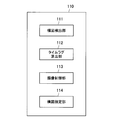
- FIG. 3 is an explanatory diagram illustrating a functional configuration example of a control unit 110 included in an imaging apparatus 100 according to an embodiment of the present disclosure.
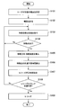
- 6 is a flowchart illustrating an operation example of the imaging apparatus 100 according to an embodiment of the present disclosure.
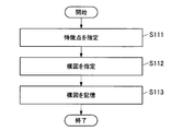
- 6 is a flowchart illustrating an operation example of the imaging apparatus 100 according to an embodiment of the present disclosure.
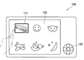
- 6 is an explanatory diagram illustrating an example of a screen displayed on the display unit 120.
- FIG. 6 is an explanatory diagram illustrating an example of a screen displayed on the display unit 120.
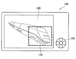
- FIG. 10 is an explanatory diagram for explaining a case where a user of the image apparatus 100 specifies a wider range.
- FIG. 1 is an explanatory diagram illustrating an external appearance example of the imaging apparatus 100 according to an embodiment of the present disclosure as a perspective view from the back side of the imaging apparatus 100.
- an appearance example of the imaging apparatus 100 according to an embodiment of the present disclosure will be described with reference to FIG.
- the imaging apparatus 100 includes a housing 101 provided with a display unit 120 and an operation unit 130.
- the display unit 120 displays an image captured by the image capturing apparatus 100 and displays various setting screens of the image capturing apparatus 100. As will be described later, the display unit 120 is provided with a touch panel, and the user of the imaging device 100 can operate the imaging device 100 by touching the touch panel provided on the display unit 120 with an operation member such as a finger. .
- the operation unit 130 is for causing the user to operate the imaging apparatus 100, and includes buttons, switches, and the like for operating the imaging apparatus 100.
- a zoom button 131, a shutter button 132, and a power button 133 are illustrated as the operation unit 130.
- the zoom button 131 is a button for changing the magnification at the time of imaging with the imaging apparatus 100.
- the shutter button 132 is a button for capturing an image with the imaging apparatus 100.
- the power button 133 is a button for turning on / off the power of the imaging apparatus 100.
- the appearance of the imaging apparatus 100 is not limited to the example.
- the buttons and switches constituting the operation unit 130 are not limited to those shown in FIG.
- the imaging apparatus 100 automatically starts an imaging operation when a subject specified by the user reaches a position specified by the user.
- the imaging apparatus 100 according to an embodiment of the present disclosure takes into account a time lag from composition detection to the start of the imaging operation during the automatic imaging operation. By taking into account the time lag from the detection of the composition to the start of the imaging operation, the imaging apparatus 100 according to an embodiment of the present disclosure can realize imaging with the composition intended by the user.
- the appearance of the imaging apparatus 100 according to the embodiment of the present disclosure illustrated in FIG. 1 is merely an example, and the appearance of the imaging apparatus 100 is not limited to that illustrated in FIG. It goes without saying that it can be taken.
- FIG. 2 is an explanatory diagram illustrating a functional configuration example of the imaging apparatus 100 according to an embodiment of the present disclosure.
- a functional configuration example of the imaging apparatus 100 according to an embodiment of the present disclosure will be described with reference to FIG.
- the imaging apparatus 100 includes an imaging unit 102, a control unit 110, a display unit 120, an operation unit 130, a flash memory 140, and a RAM 150. Consists of including.
- the imaging unit 102 includes a lens, a CCD (Charge Coupled Device), a solid-state imaging device such as a CMOS (Complementary Metal Oxide Semiconductor), a timing generator that controls the exposure timing of the image sensor, a sample hold circuit, and an imager An interface unit or the like for providing original data of an image obtained by exposure to a subsequent circuit.
- CMOS Complementary Metal Oxide Semiconductor
- An interface unit or the like for providing original data of an image obtained by exposure to a subsequent circuit.
- the control unit 110 controls the operation of the imaging apparatus 100.
- the control unit 110 may control the operation of the imaging apparatus 100 by reading out a computer program recorded in the flash memory 140 and sequentially executing the computer program.
- a specific configuration example of the control unit 110 will be described in detail later.
- the display unit 120 displays an image captured by the imaging unit 100 by the imaging unit 100 or displays various setting screens of the imaging device 100.
- the display unit 120 includes a display panel 121 and a touch panel 122.
- the display panel 121 displays an image captured by the image capturing apparatus 100 and displays various setting screens of the image capturing apparatus 100.
- the display panel 121 includes a flat panel display panel such as a liquid crystal display panel or an organic EL display panel. It is.
- the touch panel 122 is provided on the display surface of the display panel 121. The user can operate the imaging apparatus 100 by touching the touch panel 122 with an operation member such as a finger. Therefore, the control unit 110 executes various processes according to the contact state of the operation member with the touch panel 122.
- the operation unit 130 is for causing the user to operate the imaging apparatus 100, and includes a button, a switch, or the like for operating the imaging apparatus 100.
- the control unit 110 executes various processes according to the operation state of the operation unit 130.
- Various processes executed by the control unit 110 in accordance with the operation state of the operation unit 130 include, for example, power on / off processing of the imaging apparatus 100, magnification change processing during imaging, other imaging condition change processing, still image or For example, a moving image capturing process.
- the flash memory 140 is a non-volatile memory in which various computer programs and various data necessary for the processing of the control unit 110 are stored.
- the RAM 150 is a working memory used when the control unit 110 performs processing.
- control unit 110, the display unit 120, the operation unit 130, the flash memory 140, and the RAM 150 are connected to each other via the bus 160, and can communicate with each other.
- the functional configuration example of the imaging apparatus 100 according to an embodiment of the present disclosure has been described above with reference to FIG. Next, a functional configuration example of the control unit 110 included in the imaging device 100 according to an embodiment of the present disclosure will be described.
- FIG. 3 is an explanatory diagram illustrating a functional configuration example of the control unit 110 included in the imaging apparatus 100 according to an embodiment of the present disclosure.
- a functional configuration example of the control unit 110 included in the imaging apparatus 100 according to an embodiment of the present disclosure will be described with reference to FIG.
- control unit 110 includes a composition detection unit 111, a time lag calculation unit 112, an imaging control unit 113, and a composition designation unit 114.
- the composition detection unit 111 detects whether the image captured by the imaging unit 102 has a composition intended by the user. In the present embodiment, the composition detection unit 111 determines whether the image captured by the imaging unit 102 is based on whether the feature point of the subject specified by the user is located on the display unit 120 specified by the user. Detects whether the intended composition is achieved. In addition, when the feature point of the subject specified by the user is present in the image captured by the imaging unit 102, the composition detection unit 111 displays the feature point at a location on the display unit 120 specified by the user. Calculate the time to reach.
- composition detection unit 111 When the composition detection unit 111 detects that the feature point of the subject specified by the user exists at a location on the display unit 120 specified by the user, the composition detection unit 111 automatically performs an imaging operation on the imaging control unit 113 described later. Issue a trigger to start.
- the composition detection unit 111 issues the trigger to the image capturing control unit 113, the hardware factor or software factor of the image capturing apparatus 100 until the image capturing control unit 113 starts the image capturing process.
- the hardware factor or software factor of the image capturing apparatus 100 until the image capturing control unit 113 starts the image capturing process.
- the time lag calculation unit 112 described later calculates the time from when the composition detection unit 111 issues the trigger to the imaging control unit 113 until the imaging control unit 113 starts the imaging process. .
- the composition detection unit 111 issues a trigger for automatically starting the imaging operation to the imaging control unit 113 in consideration of the time calculated by the time lag calculation unit 112.
- the imaging apparatus 100 considers the time from when the composition detection unit 111 issues the trigger to the imaging control unit 113 until the imaging control unit 113 starts the imaging process. By inserting it, it becomes possible to obtain an image having a composition as intended by the user.
- the time lag calculation unit 112 calculates the time (time lag) from when the composition detection unit 111 issues the trigger to the imaging control unit 113 until the imaging control unit 113 starts the imaging process. .
- this time lag is caused by hardware factors or software factors of the image capturing apparatus 100 and an environment during image capturing.
- the time lag calculation unit 112 is a time period (time lag) from when the composition detection unit 111 issues the trigger to the imaging control unit 113 until the imaging control unit 113 starts the imaging process, which is caused by the factors that cause these time lags. ) And notifies the composition detection unit 111 of the calculated time.
- the composition detection unit 111 issues the trigger to the imaging control unit 113 in consideration of the time calculated by the time lag calculation unit 112.
- the imaging control unit 113 executes imaging processing in response to a user pressing the shutter button 132 or receiving a trigger for starting an imaging operation from the composition detection unit 111.
- the imaging control unit 113 instructs the imaging unit 102 to acquire a captured image in response to the user pressing the shutter button 132 or receiving a trigger for starting an imaging operation from the composition detection unit 111.
- a captured image acquired by an instruction from the imaging control unit 113 is stored in the flash memory 140 or displayed on the display unit 120.
- the composition specifying unit 114 allows the user to specify an arbitrary composition. Information relating to the composition designated by the user by the composition designating unit 114 is stored in the flash memory 140. When the user designates the composition, the composition designation unit 114 causes the subject (or the feature point of the subject) to be designated and the position in the image where the subject is desired to appear.
- control unit 110 The function configuration example of the control unit 110 according to an embodiment of the present disclosure has been described above with reference to FIG. Next, an operation example of the imaging apparatus 100 according to an embodiment of the present disclosure will be described.
- FIG. 4 is a flowchart illustrating an operation example of the imaging apparatus 100 according to an embodiment of the present disclosure.
- FIG. 4 illustrates an operation example of the imaging apparatus 100 when the control unit 110 detects the content of the image captured by the imaging unit 102 and automatically executes the imaging operation. is there.
- an operation example of the imaging apparatus 100 according to an embodiment of the present disclosure will be described with reference to FIG.
- the imaging apparatus 100 causes the user to specify an arbitrary composition (step S101).
- the composition designation in step S101 is executed by, for example, the composition designation unit 114.
- the imaging apparatus 100 stores the designated composition (step S102).
- This step S102 is executed by, for example, storing in the flash memory 140 information related to the composition that the composition designating unit 114 has designated by the user.
- FIG. 5 is a flowchart illustrating an operation example of the imaging apparatus 100 according to an embodiment of the present disclosure.
- FIG. 5 shows the composition designation process in step S101 of FIG. 4 in more detail.
- the composition specifying unit 114 causes the user to specify the feature points of the subject to be processed (step S111).
- FIG. 6 is an explanatory diagram illustrating an example of a screen displayed on the display unit 120 when the feature point of the target subject is designated by the user in step S111.
- FIG. 6 shows a Shinkansen vehicle body, a human face, a cat face, a moon, a bird face, and an airplane body as clockwise examples from the upper left as subject feature points to be designated by the user.
- the feature points of the subject specified by the user are not limited to those.
- the imaging apparatus 100 may prepare an example of feature points of a subject in advance and allow the user to select a feature point, or may cause a user to specify a feature point of an arbitrary object.
- FIG. 6 shows a state where the user has selected a Shinkansen vehicle body as a subject, and the Shinkansen vehicle body is surrounded by a frame line 171.
- the touch panel 122 is provided in the imaging apparatus 100, the feature point of the subject is designated by causing the user to touch the display unit 120 with a finger as shown in FIG.
- the present disclosure is not limited to the example in which the feature point of the target subject is designated, and the feature point of the subject may be designated by causing the user to operate the operation unit 130.
- FIG. 7 is an explanatory diagram illustrating an example of a screen displayed on the display unit 120 when the user designates a composition in step S112.
- an example of a screen displayed on the display unit 120 when the user selects the Shinkansen vehicle body as a subject feature point and designates the position of the Shinkansen vehicle body is shown.
- the composition is designated by causing the user to touch the display unit 120 with a finger.
- FIG. 7 shows a frame line 172 for designating the composition.
- the present disclosure is not limited to the example in which the composition is designated, and the composition may be designated by causing the user to operate the operation unit 130.
- the composition designating unit 114 When the user designates an arbitrary composition in this way, for example, the composition designating unit 114 then stores the designated composition in the flash memory 140 (step S102).
- step S102 the imaging apparatus 100 continues to detect whether the feature point designated by the user is included in the image captured by the imaging unit 102 or not. Is executed (step S103). This feature point detection process is executed by, for example, the composition detection unit 111.
- the imaging apparatus 100 determines whether the feature point designated by the user is included in the image captured by the imaging unit 102 (step S104). For example, the composition detection unit 111 executes the determination process in step S104.
- step S104 if the feature point designated by the user is not included in the image captured by the imaging unit 102, the process returns to step S103, and the imaging device 100 executes the feature point detection process again. To do.
- step S104 if the feature point designated by the user is included in the image captured by the image capturing unit 102, the image capturing apparatus 100 subsequently moves the detected feature point in the moving direction. Then, the moving speed is obtained (step S105). For example, the composition detection unit 111 executes the process of obtaining the moving direction and moving speed of the detected feature point in step S105.
- FIG. 8 is an explanatory diagram for explaining the process of obtaining the moving direction and moving speed of the detected feature point in step S105.
- the composition detection unit 111 can obtain the moving direction of the feature point by detecting that the feature point is moving from the upper left to the lower right of the image. If it can be detected that the detected feature point is moving linearly as shown in FIG. 8, the composition detection unit 111 can obtain the moving speed of the feature point.
- step S105 When the moving direction and moving speed of the detected feature point are obtained in step S105, the imaging apparatus 100 subsequently moves to the position designated by the user when the detected feature point is moving linearly.
- the time for the detected feature point to reach is calculated (step S106).
- the composition detection unit 111 executes the time calculation processing in step S106.
- FIG. 9 is an explanatory diagram for explaining the time calculation process in step S106.
- the feature point is located at the position designated by the user at time T1 after 900 milliseconds, for example, from the moving speed of the feature point.
- the composition detection unit 111 can calculate that it has reached.
- the imaging apparatus 100 calculates the time lag from when the imaging start trigger is issued until the imaging operation starts.
- the release correction time is determined (step S107).
- the release correction time is a time corresponding to the difference between the time when the feature point reaches the position designated by the user and the time when the trigger for actually starting imaging is issued.
- the time lag calculation process in step S107 is executed by the time lag calculation unit 112, for example.
- examples of factors that cause a time lag include, for example, the inherent processing speed of the imaging apparatus 100, the driving speed of the shutter curtain and the aperture of the imaging apparatus 100, the driving speed of the shutter curtain and the aperture specific to the lens, and the imaging apparatus.
- There are a processing speed that dynamically changes depending on the control state of 100 a processing speed that dynamically changes depending on the control state of the lens, and the like.
- the time lag from the state of the imaging device 100 or the lens depends on the processing performance of the imaging device 100.
- step S107 the time lag calculation unit 112 starts from when the composition detection unit 111 issues the trigger to the imaging control unit 113 until the imaging control unit 113 starts imaging processing. Time is calculated and the calculated time is notified to the composition detection unit 111.
- FIG. 10 is an explanatory diagram for explaining the time lag calculation processing in step S107.
- the time lag calculation unit 112 calculates that the time lag from when the imaging start trigger is issued to when the imaging operation is started is 20 milliseconds as a result of the time lag calculation process in step S107
- the time lag calculation unit 112 detects composition of the time lag information. Notification to the unit 111.
- the time lag calculation unit 112 may obtain the time lag by calculation when the feature point of the subject is detected. However, when the processing performance of the imaging device 100 is not high, the time lag calculation unit 112 is based on the setting state of the imaging device 100. Alternatively, a fixed value held in advance may be referred to.
- the imaging apparatus 100 determines whether the release timing has been reached from the time calculated in step S106 and the release correction time determined in step S107 ( Step S108).
- the determination of whether or not the release timing has been reached in step S108 is executed by, for example, the composition detection unit 111.
- a time lag release correction time
- the imaging apparatus 100 issues an imaging start trigger 20 milliseconds before the time T1 calculated in step S106, the imaging apparatus 100 captures an image in which a feature point exists at the position specified by the user. can do.
- step S108 if it is determined that the release timing has not been reached, the imaging apparatus 100 executes the feature point detection process in step S103 again. On the other hand, if it is determined that the release timing has been reached as a result of the determination in step S108, the imaging apparatus 100 performs release by issuing a trigger for starting imaging (step S109).
- the composition detection unit 111 issues a trigger for starting imaging to the imaging control unit 113.
- the imaging apparatus 100 performs the automatic imaging process in consideration of the time lag from when the imaging start trigger is issued until the imaging operation is started. As described above, by performing the automatic imaging process in consideration of the time lag, the imaging apparatus 100 according to an embodiment of the present disclosure executes imaging of the image with the composition specified by the user as the user intends. can do.
- the image capturing apparatus 100 may display the image captured by the release on the display unit 120 after executing the release in step S109, and correct the release correction time and the release timing when displaying the image. If not, the position of the subject may be superimposed on the image. In the above example, the imaging apparatus 100 may display the release correction time such as “20 msec” and superimpose it on the image. In addition, the imaging apparatus 100 may represent the position of the subject when correction is not performed by shifting the subject itself by image processing, or may be represented by an arbitrary mark or the like instead of the subject itself.
- the release correction time and the position of the subject when the release timing is not corrected are displayed superimposed on the image, so that the skill of the user of the imaging apparatus 100 regarding the release timing can be expected to improve.
- the imaging apparatus 100 starts the imaging operation after the time T1 when the feature point reaches the position specified by the user and the imaging start trigger are issued.
- the time lag to do was calculated.
- the subject to be imaged by the user using the imaging device 100 does not necessarily move linearly in the image, and may move in a curved manner in the image.
- the time lag is calculated as described above, and even if the imaging device 100 determines that the release timing has come, the user actually The subject may not exist at the specified position.
- the imaging apparatus 100 may allow position designation in a wider range, rather than position designation at one point on the screen, that is, so-called pinpoint position designation, when the user designates the composition. Further, in addition to pinpoint position designation, the imaging apparatus 100 designates a range in which the subject is assumed to move linearly, and when the subject is within the range, the user designates as described above. The time T1 at which the feature point arrives at the position and the time lag from when the imaging start trigger is issued until the imaging operation is started may be calculated.
- FIG. 11 is an explanatory diagram for explaining a case where the user of the imaging apparatus 100 is allowed to specify a wider range rather than pinpointing a position.
- a reference numeral 173 in FIG. 11 is a frame line indicating a range designated by the user.
- the composition specifying unit 114 may allow the user to specify a wider range than when the position is specified by pinpoint.
- the imaging apparatus 100 may automatically determine whether the position is specified in a pinpoint or in a wider range from the movement of the feature points. For example, if the feature point moves linearly within a certain time range, the imaging apparatus 100 may execute an automatic imaging process based on pinpoint position designation.
- the imaging apparatus 100 has performed the automatic imaging process of still images taking into account the time lag from when the trigger for starting imaging is issued until the imaging operation is started. It is not limited to examples.
- the imaging apparatus 100 may start the moving image imaging operation when the subject reaches the vicinity of the location specified by the user, and may end the moving image imaging operation when the subject moves away from the vicinity of the location specified by the user. . Then, the imaging apparatus 100 may extract a frame in which a subject is present at a location designated by the user from the moving images thus captured and record the frame as a still image.
- the imaging apparatus 100 that performs the automatic imaging process of a still image taking into account the time lag from when the trigger for starting imaging is issued until the imaging operation is started. Can be provided. By executing the still image automatic imaging process taking into account the time lag, the imaging apparatus 100 captures a still image with a composition reflecting the user's intention even when the subject moves at high speed. Can do.
- each step in the processing executed by each device in this specification does not necessarily have to be processed in chronological order in the order described as a sequence diagram or flowchart.
- each step in the processing executed by each device may be processed in an order different from the order described as the flowchart, or may be processed in parallel.
- a digital still camera has been described as an example.
- an apparatus to which the present disclosure is applied is not limited to such an example.
- the technology according to the present disclosure can also be provided in a mobile phone, a game machine, a personal computer, a tablet terminal, and other information processing apparatuses equipped with a camera.
- this technique can also take the following structures.
- a composition detection unit that calculates a time when the subject specified by the user included in the captured image becomes the composition specified by the user;
- a time calculation unit for calculating a time from when an instruction to start an imaging operation is performed until an image is captured;
- An imaging control unit that starts an imaging process of an image in response to an instruction to start an imaging operation;
- the composition detection unit instructs the imaging control unit to start an imaging operation before a time calculated by the time calculation unit from a time when the composition specified by the user is reached.
- the imaging control unit superimposes the time information calculated by the time calculation unit on an image obtained by an imaging operation performed based on an instruction from the composition detection unit.
- the imaging control unit converts information on the position of the subject when the imaging operation is executed at the time calculated by the composition detection unit into an image obtained by the imaging operation executed based on an instruction from the composition detection unit.
- the composition detection unit according to any one of (1) to (5), wherein the composition detection unit instructs the imaging control unit to start an imaging operation only when the subject is continuously included in the captured image. Imaging device.
- composition detection unit changes a timing for starting calculation of a time at which the composition specified by the user starts according to a method for specifying the composition by the user. apparatus.
- a method of specifying a composition by the user is changed depending on whether the subject moves linearly or curvedly.
- the composition detection step is a computer program for instructing to start an imaging operation in the imaging control step when the composition calculation step is before the time calculated in the time calculation step from the time specified by the user.
Landscapes
- Engineering & Computer Science (AREA)
- Multimedia (AREA)
- Signal Processing (AREA)
- Physics & Mathematics (AREA)
- General Physics & Mathematics (AREA)
- Human Computer Interaction (AREA)
- Studio Devices (AREA)
Abstract
L'invention a pour but de proposer un dispositif d'imagerie apte à réaliser une détection de composition et un traitement d'imagerie automatique qui prennent en compte un écoulement de temps de la détection d'une composition au début d'une opération d'imagerie. A cet effet, l'invention concerne un dispositif d'imagerie comportant : une unité de détection de composition qui calcule un instant auquel un sujet spécifié par l'utilisateur inclus dans une image qui est imagée adoptera une composition spécifiée par l'utilisateur ; une unité de calcul d'intervalle de temps qui calcule un intervalle de temps s'étendant de la délivrance d'une instruction de départ pour une opération d'imagerie, jusqu'à ce que l'image soit imagée ; et une unité de commande d'imagerie qui reçoit l'instruction de départ pour l'opération d'imagerie, et commence le traitement d'imagerie pour l'image. L'unité de détection de composition donne l'instruction à l'unité de commande d'imagerie de commencer l'opération d'imagerie à un moment qui est un intervalle de temps avant l'instant auquel la composition spécifiée par l'utilisateur est adoptée, ledit intervalle de temps étant l'intervalle de temps calculé par l'unité de calcul d'intervalle de temps.
Priority Applications (1)
| Application Number | Priority Date | Filing Date | Title |
|---|---|---|---|
| US14/763,091 US9554035B2 (en) | 2013-02-07 | 2014-01-22 | Image pickup device, method of controlling image pickup device, and computer program for automatically achieving composition specified by user |
Applications Claiming Priority (2)
| Application Number | Priority Date | Filing Date | Title |
|---|---|---|---|
| JP2013-022247 | 2013-02-07 | ||
| JP2013022247 | 2013-02-07 |
Publications (1)
| Publication Number | Publication Date |
|---|---|
| WO2014122990A1 true WO2014122990A1 (fr) | 2014-08-14 |
Family
ID=51299587
Family Applications (1)
| Application Number | Title | Priority Date | Filing Date |
|---|---|---|---|
| PCT/JP2014/051219 Ceased WO2014122990A1 (fr) | 2013-02-07 | 2014-01-22 | Dispositif d'imagerie, procédé de commande pour un dispositif d'imagerie et programme d'ordinateur |
Country Status (2)
| Country | Link |
|---|---|
| US (1) | US9554035B2 (fr) |
| WO (1) | WO2014122990A1 (fr) |
Citations (2)
| Publication number | Priority date | Publication date | Assignee | Title |
|---|---|---|---|---|
| JP2002335436A (ja) * | 2001-05-08 | 2002-11-22 | Fuji Photo Film Co Ltd | カメラ |
| JP2005215373A (ja) * | 2004-01-30 | 2005-08-11 | Konica Minolta Photo Imaging Inc | 撮像装置 |
Family Cites Families (9)
| Publication number | Priority date | Publication date | Assignee | Title |
|---|---|---|---|---|
| JP3814363B2 (ja) * | 1997-02-18 | 2006-08-30 | キヤノン株式会社 | カメラ |
| US7027087B2 (en) * | 1998-08-21 | 2006-04-11 | Nikon Corporation | Electronic camera |
| JP2003222790A (ja) * | 2002-01-31 | 2003-08-08 | Minolta Co Ltd | カメラ |
| JP2005107213A (ja) * | 2003-09-30 | 2005-04-21 | Olympus Corp | カメラの自動焦点調節装置 |
| US7773872B2 (en) * | 2007-02-19 | 2010-08-10 | Canon Kabushiki Kaisha | Camera having a function of predicting a future image plane position from a change in a plurality of past image plane positions and of time detection, a photographic lens to be mounted on the same, and a camera system |
| EP1986421A3 (fr) * | 2007-04-04 | 2008-12-03 | Nikon Corporation | Appareil photographique numérique |
| JP5225065B2 (ja) * | 2008-12-27 | 2013-07-03 | キヤノン株式会社 | 撮像装置及び撮像方法 |
| JP2012099984A (ja) | 2010-10-29 | 2012-05-24 | Fujifilm Corp | 撮像装置及び表示制御方法 |
| JP2011139498A (ja) | 2011-02-14 | 2011-07-14 | Fujifilm Corp | 撮像装置およびその制御方法 |
-
2014
- 2014-01-22 WO PCT/JP2014/051219 patent/WO2014122990A1/fr not_active Ceased
- 2014-01-22 US US14/763,091 patent/US9554035B2/en active Active
Patent Citations (2)
| Publication number | Priority date | Publication date | Assignee | Title |
|---|---|---|---|---|
| JP2002335436A (ja) * | 2001-05-08 | 2002-11-22 | Fuji Photo Film Co Ltd | カメラ |
| JP2005215373A (ja) * | 2004-01-30 | 2005-08-11 | Konica Minolta Photo Imaging Inc | 撮像装置 |
Also Published As
| Publication number | Publication date |
|---|---|
| US20150373260A1 (en) | 2015-12-24 |
| US9554035B2 (en) | 2017-01-24 |
Similar Documents
| Publication | Publication Date | Title |
|---|---|---|
| US10270975B2 (en) | Preview image display method, apparatus and storage medium | |
| US9106836B2 (en) | Imaging apparatus, control method for the same, and recording medium, where continuous shooting or single shooting is performed based on touch | |
| US20100166404A1 (en) | Device and Method Using a Touch-Detecting Surface | |
| JP2017069618A (ja) | 電子機器及び撮像方法 | |
| KR20170042491A (ko) | 전자기기 및 그 제어 방법 | |
| JP6414218B2 (ja) | 制御装置、制御方法及びプログラム | |
| KR101493591B1 (ko) | 촬상 장치 및 촬상 처리 방법과 기억 매체 | |
| US20130329110A1 (en) | Image capturing apparatus and control method therefor | |
| JP2013009189A (ja) | 撮影装置および撮像方法 | |
| JP2013179536A (ja) | 電子機器及びその制御方法 | |
| JP2014068081A (ja) | 撮像装置及びその制御方法、プログラム、並びに記憶媒体 | |
| JP2005143112A (ja) | カメラ及びこれに関連する方法 | |
| JP7292033B2 (ja) | 情報処理装置、情報処理方法、撮像装置、及びプログラム | |
| JP4910584B2 (ja) | 撮像装置、携帯電話、撮像制御方法、撮像制御プログラムおよびプログラム記録媒体 | |
| US9232133B2 (en) | Image capturing apparatus for prioritizing shooting parameter settings and control method thereof | |
| JP5777446B2 (ja) | 表示制御装置及びその制御方法 | |
| JP2010193049A (ja) | 電子カメラ | |
| WO2014122990A1 (fr) | Dispositif d'imagerie, procédé de commande pour un dispositif d'imagerie et programme d'ordinateur | |
| JP6124535B2 (ja) | 表示制御装置、制御方法、プログラム及び記憶媒体 | |
| JP2008098954A (ja) | 撮像装置及び方法並びにプログラム | |
| JP6270508B2 (ja) | 撮像装置および撮像装置の画像表示方法 | |
| JP5633679B2 (ja) | 撮像装置およびプログラム | |
| JP2006317778A (ja) | 撮影装置 | |
| JP6762856B2 (ja) | 撮像装置およびその制御方法 | |
| JP5700072B2 (ja) | 撮像装置および撮像方法 |
Legal Events
| Date | Code | Title | Description |
|---|---|---|---|
| 121 | Ep: the epo has been informed by wipo that ep was designated in this application |
Ref document number: 14749215 Country of ref document: EP Kind code of ref document: A1 |
|
| WWE | Wipo information: entry into national phase |
Ref document number: 14763091 Country of ref document: US |
|
| NENP | Non-entry into the national phase |
Ref country code: DE |
|
| 122 | Ep: pct application non-entry in european phase |
Ref document number: 14749215 Country of ref document: EP Kind code of ref document: A1 |
|
| NENP | Non-entry into the national phase |
Ref country code: JP |