WO2014123012A1 - 清掃具 - Google Patents
清掃具 Download PDFInfo
- Publication number
- WO2014123012A1 WO2014123012A1 PCT/JP2014/051587 JP2014051587W WO2014123012A1 WO 2014123012 A1 WO2014123012 A1 WO 2014123012A1 JP 2014051587 W JP2014051587 W JP 2014051587W WO 2014123012 A1 WO2014123012 A1 WO 2014123012A1
- Authority
- WO
- WIPO (PCT)
- Prior art keywords
- cleaning
- sheet
- strip
- cleaning tool
- region
- Prior art date
- Legal status (The legal status is an assumption and is not a legal conclusion. Google has not performed a legal analysis and makes no representation as to the accuracy of the status listed.)
- Ceased
Links
Images







Classifications
-
- A—HUMAN NECESSITIES
- A47—FURNITURE; DOMESTIC ARTICLES OR APPLIANCES; COFFEE MILLS; SPICE MILLS; SUCTION CLEANERS IN GENERAL
- A47L—DOMESTIC WASHING OR CLEANING; SUCTION CLEANERS IN GENERAL
- A47L13/00—Implements for cleaning floors, carpets, furniture, walls, or wall coverings
- A47L13/10—Scrubbing; Scouring; Cleaning; Polishing
- A47L13/38—Other dusting implements
-
- A—HUMAN NECESSITIES
- A47—FURNITURE; DOMESTIC ARTICLES OR APPLIANCES; COFFEE MILLS; SPICE MILLS; SUCTION CLEANERS IN GENERAL
- A47L—DOMESTIC WASHING OR CLEANING; SUCTION CLEANERS IN GENERAL
- A47L13/00—Implements for cleaning floors, carpets, furniture, walls, or wall coverings
- A47L13/10—Scrubbing; Scouring; Cleaning; Polishing
- A47L13/12—Implements with several different treating devices
-
- A—HUMAN NECESSITIES
- A47—FURNITURE; DOMESTIC ARTICLES OR APPLIANCES; COFFEE MILLS; SPICE MILLS; SUCTION CLEANERS IN GENERAL
- A47L—DOMESTIC WASHING OR CLEANING; SUCTION CLEANERS IN GENERAL
- A47L13/00—Implements for cleaning floors, carpets, furniture, walls, or wall coverings
- A47L13/10—Scrubbing; Scouring; Cleaning; Polishing
- A47L13/42—Details
- A47L13/44—Securing scouring-cloths to the brush or like body of the implement
-
- A—HUMAN NECESSITIES
- A47—FURNITURE; DOMESTIC ARTICLES OR APPLIANCES; COFFEE MILLS; SPICE MILLS; SUCTION CLEANERS IN GENERAL
- A47L—DOMESTIC WASHING OR CLEANING; SUCTION CLEANERS IN GENERAL
- A47L13/00—Implements for cleaning floors, carpets, furniture, walls, or wall coverings
- A47L13/10—Scrubbing; Scouring; Cleaning; Polishing
-
- A—HUMAN NECESSITIES
- A47—FURNITURE; DOMESTIC ARTICLES OR APPLIANCES; COFFEE MILLS; SPICE MILLS; SUCTION CLEANERS IN GENERAL
- A47L—DOMESTIC WASHING OR CLEANING; SUCTION CLEANERS IN GENERAL
- A47L13/00—Implements for cleaning floors, carpets, furniture, walls, or wall coverings
- A47L13/10—Scrubbing; Scouring; Cleaning; Polishing
- A47L13/16—Cloths; Pads; Sponges
-
- A—HUMAN NECESSITIES
- A47—FURNITURE; DOMESTIC ARTICLES OR APPLIANCES; COFFEE MILLS; SPICE MILLS; SUCTION CLEANERS IN GENERAL
- A47L—DOMESTIC WASHING OR CLEANING; SUCTION CLEANERS IN GENERAL
- A47L13/00—Implements for cleaning floors, carpets, furniture, walls, or wall coverings
- A47L13/10—Scrubbing; Scouring; Cleaning; Polishing
- A47L13/20—Mops
Definitions
- the present invention relates to a cleaning tool for cleaning an object to be cleaned.
- Japanese Patent Application Laid-Open No. 2007-137466 describes a handle insertion part and a cleaning article provided with a fiber layer and a scraping sheet above and below the handle insertion part.
- the handle insertion portion is formed by a pair of handle mounting sheets.
- This cleaning article is used by being attached to a handle.
- the end of the cleaning article described in JP-A-2007-137666 in the longitudinal cross direction is formed in a zigzag shape.
- an object of the present invention is to provide a cleaning tool having a high cleaning effect.
- the cleaning sheet is held on the cleaning sheet.
- the cleaning tool is configured to extend in both the cleaning sheet longitudinal direction defined by the direction in which the tool is inserted and the cleaning sheet longitudinal intersecting direction defined by the direction intersecting with the cleaning sheet longitudinal direction.
- a brush unit configured to be able to clean a cleaning target; and a brush unit having a holding unit for holding the cleaning sheet, and a gripping unit connected to the holding unit and gripped by a user.
- a base part to which the part is connected, and an insertion part that is formed in the base part and into which the holding part is inserted, and the brush part has a plurality of strips formed by strip-shaped sheets,
- the strip has a first strip and a second strip having higher rigidity than the first strip, and the second strip can scrape dust to be cleaned. Has a scraped part.
- the second strip has a highly rigid region.
- the said strip piece is a strip piece length prescribed
- the said 2nd strip piece is provided in the edge part area
- the said 2nd strip piece is provided in the center area
- the said 2nd strip piece is provided in the edge part area
- the said 2nd strip piece is provided in the center area
- the first strip pieces and the second strip pieces are alternately arranged.
- the said base is formed of the 1st sheet
- the said base has a some cutting part provided in the edge part of the said 1st sheet
- the said strip piece is a plurality of said cutting parts. Formed between.
- the cleaning tool which concerns on this invention, it has a 2nd sheet body overlapped with the said 1st sheet body,
- the said insertion part has the said 1st sheet body, the said 2nd, and sheet
- the cleaning tool which concerns on this invention, while the said insertion part contact
- the cleaning tool which concerns on this invention, It has a 3rd sheet
- the insertion portion is formed between the third sheet body and the fourth and sheet bodies.
- the cleaning tool which concerns on this invention, it has a 5th sheet body piled up on a said 1st sheet body,
- the said insertion part hits predetermined surfaces in the said 5th sheet body. It forms by joining and forming the joining sheet area
- the said brush part is provided in the one side of the said base.
- the said brush part is provided in the other side which is the one side of the said base, and the other side which is the said one side.
- a cleaning tool having a high cleaning effect can be provided by the scraping portion of the second strip.
- FIG. 6 is a cross-sectional view taken along line IX-IX in FIG. 5. It is a figure which shows the state which engaged the cleaning body holder with the cleaning body.
- FIG. 10 is a cross-sectional view taken along line IIX-IIX in FIG.
- the cleaning object to be cleaned using this cleaning tool A is to be cleaned in a room, outdoor, outdoor such as a detached house, condominium, building, factory, vehicle, etc. (floor surface, wall surface, window, ceiling surface, outer wall surface, furniture) Surface, clothes, curtains, bedding, lighting, home appliances, etc.) and surfaces to be cleaned in each component of the human body.
- These various surfaces to be cleaned may be configured as a flat surface, or may be configured as a curved surface, an uneven surface, or a step surface.
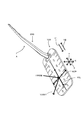
- the cleaning tool A includes a cleaning body holder 200 and a cleaning body 100.
- the cleaning body holder 200 is detachably attached to the cleaning body 100 and is configured to hold the cleaning body 100.
- This cleaning tool A is an example of the “cleaning tool” in the present invention.
- This cleaning body holder 200 is an example of the “holder” in the present invention.
- This cleaning body 100 is an example of the “cleaning sheet” in the present invention.
- the cleaning body 100 is configured to extend in both the cleaning body longitudinal direction Y and the cleaning body longitudinal intersecting direction X defined by the direction intersecting with the cleaning body longitudinal direction Y.
- the cleaning body longitudinal direction Y is defined by a direction parallel to the direction in which the cleaning body holder 200 is inserted into the cleaning body 100.
- the direction in which the cleaning body holder 200 is inserted into the cleaning body 100 is the insertion direction Y1.
- the direction opposite to the insertion direction Y1 is the drawing direction Y2.
- a direction intersecting with each of the cleaning body longitudinal direction Y and the cleaning body longitudinal crossing direction X is a thickness direction Z.
- “intersection” means “orthogonal”.
- This cleaning body longitudinal direction Y is an example of "cleaning sheet longitudinal direction” in the present invention.
- This cleaning body longitudinal cross direction X is an example of the “cleaning sheet longitudinal cross direction” in the present invention.
- the cleaning body 100 has an end portion 100B in the cleaning body longitudinal direction Y and an end portion 100A in the cleaning body longitudinal cross direction X.
- the end portion 100B has a central region 100BC as a region including the central portion.
- the end portion 100A has a central region 100AC as a region including the central portion.
- a point that is the center of the longitudinal cross direction X is defined as a longitudinal cross direction center point XCP.
- the longitudinal cross direction X for forming the longitudinal cross direction center point XCP can be appropriately selected from the longitudinal cross directions X at arbitrary locations on the cleaning body 100.
- a straight line passing through the longitudinal cross-direction center point XCP and parallel to the longitudinal direction Y is defined as a longitudinal center line YCL.
- the direction from the longitudinal crossing direction center point XCP to the region where the cleaning body 100 does not exist is defined as the outer direction 100D1. Furthermore, a direction from the region where the cleaning body 100 does not exist to the longitudinal cross direction center point XCP is defined as an inner direction 100D2.
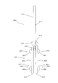
- the cleaning body holder 200 is mainly composed of a handle part 210 and a cleaning body holding part 220.
- the handle part 210 is a member that is formed in a long shape and is held by the user during cleaning.
- the handle part 210 has a handle 211 and a handle joint part 212.
- the handle joint portion 212 is joined to the connecting portion 230 of the cleaning body holding portion 220.
- the handle 211 is formed in a long shape extending from the handle joint portion 212.
- the handle portion 210 is an example of the “gripping portion” in the present invention.
- the cleaning body holding unit 220 is an example of the “holding unit” in the present invention.
- the cleaning body holding part 220 is formed of a resin material and is a member for holding the cleaning body 100.
- the cleaning body holding part 220 is mainly composed of two holding members 221 formed in a long shape, a convex part 260, a pressing plate 270, and the like.
- the cleaning body holder 220 is made of polypropylene (PP).
- maintenance part 220 can select the resin material which has flexibility suitably.
- polyethylene (PE), polyethylene terephthalate (PET), acrylonitrile-butadiene-styrene resin (ABS), and polyester-based thermoplastic elastomer can be used.
- the holding member 221 extends from the connecting portion 230 in a direction opposite to the direction in which the handle 211 extends. That is, the holding member 221 includes a connecting portion 230, a tip portion 240, and an intermediate portion 250 that extends from the connecting portion 230 toward the tip portion 240.
- the front end portions 240 of the two holding members 221 are free ends.
- the convex portion 260 is provided in the outer direction 100D1 in the intermediate portion 250.
- the convex portion 260 includes a first convex portion 261 provided on the connecting portion 230 side and a second convex portion 262 provided on the distal end portion 240 side.
- the pressing plate 270 is formed so as to protrude from the connecting portion 230.
- the holding plate 270 is formed between the pair of holding members 221 so as to extend in parallel with the holding member 221.
- the presser plate 270 is configured as a plate-like member that is curved so as to be convex downward, and further includes a locking projection (not shown) on the lower surface.
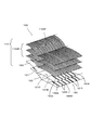
- the cleaning body 100 is a sheet-like cleaning body having a dirt collecting function for collecting dirt such as dust to be cleaned. As shown in FIGS. 4 and 5, the cleaning body 100 is formed in a rectangular shape in plan view.
- This cleaning body 100 is a disposable type that is used once as a guide, or a disposable type that is replaced with multiple uses as a guide while holding dust and dust removed from the surface to be cleaned. It may be of a type that can be used repeatedly after washing or the like.
- the base 120 is formed by the first sheet body 121.
- the base 120 has an end 120A on the longitudinal cross direction X, an end 120B on the longitudinal direction Y, one surface 120C, and the other surface 120D.
- the base 120, the first sheet body 121, the one surface 120C, and the other surface 120D are respectively the “base”, “first sheet body”, “one side”, and “the other side” in the present invention. It is an example.
- the fiber assembly 110GF is disposed on one surface 120C of the base 120.
- a second sheet body 122 is disposed on the other surface 120D of the base 120.
- These laminated base 120, fiber assembly 110 ⁇ / b> GF, and second sheet body 122 all extend in the longitudinal direction Y in the cleaning body 100.
- the fiber assembly 110GF forms a brush portion 110 having a dirt collecting function together with a strip piece 150 described later.
- This fiber assembly 110GF is an example of the “fiber assembly” according to the present invention.
- the brush portion 110 is an example of the “brush portion” in the present invention.
- the fiber aggregate 110GF is formed by an aggregate of fibers 110SF.
- the fiber 110SF is a single fiber structure composed of typical fibers, or a fiber structure in which typical fibers are aligned in the length direction and / or radial direction (twisted yarn, spun yarn, a plurality of long lengths). A thread material in which fibers are partially connected), or an aggregate of the fiber structure.
- the “typical fiber” is a structural unit such as a yarn or a woven fabric, and has a length that is sufficiently long compared to the thickness, and is in a thin and flexible form.
- long continuous fibers are long fibers (filaments), and short fibers are short fibers (staples).
- the fibers 110SF partially include thermoplastic fibers, and each fiber 110SF can be fused (also referred to as “welding”).
- the fiber aggregate 110GF is formed by a plurality of fibers 110SF arranged in parallel in a predetermined fiber orientation direction 110D and stacked in the thickness direction Z.
- the fiber orientation direction 110D substantially coincides with the longitudinal cross direction X.
- the fiber orientation direction 110D of the fiber 110SF indicates the fiber orientation in the product design.
- the fiber 110SF of the fiber assembly 110GF has a connection end portion 110SFA which is an end portion to be welded to the central joint portion 140.
- the fiber 110SF has an open end 110SFB that is an end opposite to the connection end 110SFA.
- the open end 110SFB is a free end.
- the fiber assembly 110GF is formed by laminating three fiber layers, but the number of fiber layers may be one or more as necessary.
- the fiber assembly 110GF preferably has a planar structure with a predetermined plane or curved surface, and is configured as a three-dimensional shape having a certain thickness or a thin sheet shape.
- the fiber aggregate 110GF is typically made of polyethylene (PE), polypropylene (PP), polyethylene terephthalate (PET), nylon, rayon, etc., and is practically a long fiber (filament) obtained by opening the tow. ) Is preferably used.
- the core portion is preferably made of polypropylene (PP) or polyethylene terephthalate (PET), and the sheath portion covering the outer surface of the core portion is preferably composed of a composite fiber of polyethylene (PE) to form the fiber assembly 110GF.
- the fineness 110SF of the fibers forming the fiber aggregate 110GF is preferably 1 to 50 dtex, more preferably 2 to 10 dtex.
- each fiber assembly may be composed of fibers having substantially the same fineness, or each fiber assembly may include fibers having different finenesses.
- an oil agent is supplied to the fiber assembly 110GF.
- This oil agent is mainly composed of liquid paraffin.
- the fiber assembly 110GF includes crimped fibers.
- a crimped fiber here is comprised as a fiber to which the well-known crimping process was provided, and is set as the structure where fibers are easy to get entangled.
- the fiber assembly 110GF is bulkier than the state before the cleaning body holder 200 is mounted, and a structure in which dust is easily taken into the crimped portion.
- This structure can be realized in particular by using crimped fibers formed from tow fibers.
- the second sheet body 122 is a sheet formed of a rectangular nonwoven fabric shorter than the base 120 in the longitudinal direction Y.
- the nonwoven fabric which comprises the base 120 (1st sheet body 121) and the 2nd sheet body 122 all typically the sheet-like nonwoven fabric which consists of a thermomeltable fiber (thermoplastic fiber) is used. That is, the base 120 and the second sheet body 122 are also referred to as “nonwoven fabric sheets”.
- nonwoven fabric sheets in order to improve the sweeping-out function at the time of cleaning, it is preferable to use a highly rigid nonwoven fabric.
- synthetic fibers such as polyethylene (PE), polypropylene (PP), and polyethylene terephthalate (PET), are used for this nonwoven fabric.
- nonwoven fabric As a form of a nonwoven fabric, what was formed by the air through method or the spun bond method is used. On the other hand, even if it is other than a nonwoven fabric, a cloth or a film body made of a synthetic resin can be used.
- the base 120 and the second sheet body 122 include a central joint 140 that extends along the longitudinal center line YCL of the cleaning body 100 and a plurality of first joints 141 that are located on both sides of the central joint 140. Are welded together. That is, as shown in FIG. 7, the base 120, the second sheet body 122, and the fiber assembly 110 ⁇ / b> GF are welded and joined at the central joint 140. Further, the base 120, the second sheet body 122, and a part of the fiber aggregate 110 ⁇ / b> GF are welded and joined at the first joint 141. In addition, the 1st junction part 141 located in the both ends side in the longitudinal direction Y is formed in the position where the 2nd sheet
- a pair of holding spaces 130 extending in the longitudinal direction Y are formed between the base 120 and the second sheet body 122 in a region sandwiched between the central joint 140 and the first joint 141. Yes.
- openings 131 are formed at both ends of the holding space 130 in the longitudinal direction Y, respectively.
- the holding space 130 is an example of the “insertion portion” in the present invention.
- the holding space 130 is formed by a predetermined region of the base 120 between the pair of first joining portions 141 in the longitudinal cross direction X and a predetermined region of the second sheet body 122.
- a plurality of first joint portions 141 are continuously formed substantially along the longitudinal direction Y.
- the first welded joints 141 adjacent in the longitudinal direction Y do not necessarily need to be arranged in the longitudinal direction Y.
- the arrangement form of the first welding joint portion 141 can be appropriately designed depending on the design property and the shape of the cleaning body holding portion 220. At this time, of course, the first weld joint 141 can be formed in a continuous line shape.
- the above-described central joint 140 and first joint 141 are formed by heat welding.
- the joint portion according to the present invention can also be formed by an adhesive such as ultrasonic welding, sewing, or a hot melt adhesive.
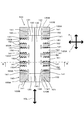
- the cleaning body 100 has a strip piece 150.
- the strip piece 150 includes a strip piece 121S formed between a plurality of cut lines provided at an end portion in the longitudinal crossing direction X in the base portion 120, and an end portion on the longitudinal crossing method X in the second sheet body 122. And strip strips 122S formed between a plurality of cut lines provided in. Note that the cut lines in the base 120 and the second sheet body 122 have a zigzag shape. By making the strips 150 into a zigzag shape, a structure with a high cleaning function that can easily catch and capture dust is realized.
- a single type or a plurality of types of shapes such as a zigzag shape, a linear shape, and a curved shape can be appropriately used.
- the strip piece 150 which concerns on this invention forms the brush part 110 with the fiber assembly 110GF.
- the strip 150 may be either the strip 121S of the base 120 or the strip 122S of the second sheet 122. That is, it is sufficient that the strip 150 is formed on any sheet-like body for forming the cleaning body 100. In this sense, the cut for forming the strip 150 is referred to as a cut portion 150A.
- This strip piece 150 is an example of a “strip piece” according to the present invention.
- the strip piece 150 includes a first strip piece 151 and a second strip piece 152 having higher rigidity than the first strip piece 151.
- the second strip 152 is subjected to hot embossing.
- the rigidity of the first strip 151 is 51.2 (mm / 25 mm)
- the rigidity of the second strip 152 is 67.6 (mm / 25 mm).
- the rigidity was measured by the JIS / L1096 cantilever method.
- the second strip 152 has a scraping portion 152A that can scrape dust to be cleaned.
- the first strip 151 is an example of the “first strip” according to the present invention.
- the second strip piece 152 is an example of the “second strip piece” according to the present invention.
- This scraping portion 152A is an example of the “scraping portion” according to the present invention.
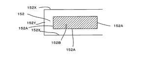
- the second strip piece 152 has a high rigidity region 152B.
- This high-rigidity region 152 ⁇ / b> B is configured to improve the rigidity of the second strip piece 152.
- a high-rigidity region 152B is formed by the heat embossing described above. Further, the high-rigidity region 152B can be achieved by other configurations. Specifically, it is formed by impregnating the second strip piece 152 with a hot melt adhesive. In addition, it is possible to appropriately select attachment of a non-woven fabric, heat melting processing, or the like to the second strip piece 152.
- This high-rigidity region 152B is an example of the “high-rigidity region” according to the present invention.
- the strip 150 is configured to extend in both the strip strip longitudinal direction 150Y defined by the direction in which the strip strip 150 extends and the strip strip longitudinal cross direction 150X defined by the direction intersecting the strip strip longitudinal direction 150Y.
- the strip piece longitudinal direction 150Y is an example of the “strip piece longitudinal direction” according to the present invention.
- the strip piece longitudinal cross direction 150X is an example of the “strip piece longitudinal cross direction” according to the present invention.
- the first strip 151 has an end 151Y that is an end on the strip piece longitudinal direction 150Y and an end 151X that is an end on the strip piece longitudinal cross direction X.
- the second strip piece 152 has an end portion 152Y which is an end portion in the strip piece longitudinal direction 150Y and an end portion 152X which is an end portion in the strip piece longitudinal cross direction X.
- the high-rigidity region 152A is formed to extend in the strip piece longitudinal direction 150Y. As a result, the second strip 152 is strengthened with respect to the longitudinal direction Y of the strip.
- the scraped portion 152A is provided at the end of the high rigidity region 152B. That is, in FIG. 6, the high-rigidity region 152 ⁇ / b> B is provided over the entire second strip piece 152. In such a case, the scraping portion 152A coincides with the end portion 152X and the end portion 152Y of the second strip piece 152. On the other hand, in FIG. 7, the high rigidity region 152 ⁇ / b> B is provided in a partial region of the second strip piece 152. In such a case, the scraping portion 152 ⁇ / b> A is provided at the end of the high-rigidity region 152 ⁇ / b> B on the region of the second strip piece 152.
- the first strip piece 151 and the second strip piece 152 are provided at the end portion 100 ⁇ / b> A on the cleaning body longitudinal cross direction X in the cleaning body 100. Further, the first strip pieces 151 and the second strip pieces 152 are alternately arranged.
- each holding member 221 can be inserted into the holding space 130.
- the cleaning body 100 is held by the cleaning body holder 200 by the holding member 221 being inserted into the holding space 130 along the insertion direction Y1.
- the cleaning body holder 200 is pulled out from the holding space 130 along the pulling direction Y2.
- the convex portion 260 is disposed between the adjacent first joint portions 141. Thereby, the engagement state of the cleaning body holder 200 and the cleaning body 100 is reliably maintained.
- the holding plate 270 holds the second sheet body 122 together with the holding member 221.
- the notch 150A is described as a straight line.
- the user brings the end 100A of the cleaning body 100 in the longitudinal cross direction X into contact with the object to be cleaned.
- the scraping portion 152A of the second strip piece 152 comes into contact with the object to be cleaned.
- dust is scraped by the scraping portion 152A.
- the second strip piece 152 since the second strip piece 152 has the high-rigidity region 152B, the second strip piece 152 is not deformed so as to greatly hinder the scraping operation.
- the present invention is not limited to the above-described embodiment, and various applications and modifications are possible.
- two holding members 211 of the holder 200 are formed, and two holding spaces 130 of the cleaning body 100 are also formed correspondingly.
- a single holding space 130 may be provided for the two holding members 211.
- a single holding space 130 can be provided for a single holding member 211.
- the cleaning body 101 which concerns on a 1st modification differs in the structure of the holding
- the central joint 140 can join only the brush part 110.
- the brush part 110 and the base part 120 can be joined by an adhesive (not shown) or the like.
- the first strip piece 151 and the second strip piece 152 are formed, and thus the same operation and effect as the cleaning body 100 in the above-described embodiment are obtained. Play.
- the cleaning body 102 which concerns on a 2nd modification differs in the structure of the holding
- a holding space 130 that is a space extending in the longitudinal direction Y can be formed between the third sheet 123 and the fourth sheet 124.
- the central joint 140 joins only the brush part 110 and the base 120.
- the third sheet 123 is joined to the base 120 with an adhesive or the like to form a fifth joint 145.
- the cleaning body 103 according to the third modification is different in the configuration of the holding space 130 from the cleaning body 100 in the above-described embodiment. That is, the holding space 130 of the cleaning body 103 according to the third modification is formed independently of the base 120. That is, predetermined surfaces of the fifth sheet body 125 are brought into contact with each other to form the joining sheet region 125A. A predetermined region in the bonding sheet region 125A is welded to form a sixth bonding portion 146. Thereby, the holding space 130 which is a space extending in the longitudinal direction Y can be formed.
- the central joint 140 joins only the brush part 110 and the base 120.
- the fifth sheet 125 is bonded to the base 120 with an adhesive or the like to form a seventh bonded portion 147. Even in the cleaning body 103 according to the third modified example, since the first strip 151 and the second strip 152 are formed, the same operations and effects as the cleaning body 100 in the above-described embodiment are obtained. Play.
- the cleaning body 104 according to the fourth modified example includes the brush portion 110 not only on the one surface 120C side of the base 120 but also on the other surface 120D side as compared with the cleaning body 100 in the above-described embodiment. Is formed. That is, the fiber assembly 110GF is overlaid on the one surface 120C side of the base 120. The second sheet 122 and the fiber assembly 110GF are overlaid on the other surface 120D of the base 120. In other words, the base body 120 and the second sheet body 122 are sandwiched between the two fiber assemblies 110GF.
- the cleaning body 105 according to the fifth modification is not limited to the one surface 120C side of the base 120 but also the other surface 120D side as compared with the cleaning body 101 in the first modification described above.
- the part 110 is formed. That is, the fiber assembly 110GF is joined to the first sheet body 121 forming the holding space 130.
- the fiber aggregate 110GF on the other surface 120D side of the base 120 is welded in the central region.
- the weld location in this central region forms a tenth joint 1410.
- the fiber assembly 110GF having the tenth joint portion 1410 is joined to the first sheet body 121 forming the holding space 130 by an adhesive (not shown) or the like. In this way, the cleaning body 105 is formed.
- the cleaning body 105 Even in the cleaning body 105 according to the fifth modified example, the first strip 151 and the second strip 152 are formed, so that the same operation and effect as the cleaning body 100 in the above-described embodiment are obtained. Play. Furthermore, since the brush part 110 is also formed on the other surface 120D side of the base part 120, the convenience of the user is improved as compared with the cleaning body 101 according to the first modification described above.
- the cleaning body 106 according to the sixth modification is not limited to the one surface 120C side of the base 120 but also the other surface 120D side as compared with the cleaning body 102 according to the second modification described above.
- the part 110 is formed. That is, the fiber assembly 110 and the sixth sheet body 126 are welded in the central region to form the eleventh joint portion 1411. Then, the surface of the sixth sheet body 126 where the fiber aggregate 110 is not disposed and the fourth sheet body 124 are joined together with an adhesive or the like to form a twelfth joining portion 1412. In this way, the cleaning body 106 is formed.
- the cleaning body 106 according to the sixth modified example since the first strip 151 and the second strip 152 are formed, the same operations and effects as the cleaning body 100 in the above-described embodiment are obtained. Play. Furthermore, since the brush part 110 is also formed on the other surface 120D side of the base part 120, the convenience of the user is improved as compared with the cleaning body 102 according to the second modified example.
- the cleaning body 107 according to the seventh modification is not limited to the one surface 120C side of the base 120 but also the other surface 120D side, as compared with the cleaning body 103 according to the third modification described above.
- the part 110 is formed. That is, the fiber assembly 110 and the seventh sheet body 127 are welded in the central region to form the thirteenth joint portion 1413. Then, the surface of the seventh sheet body 127 on which the fiber assembly 110 is not disposed and the fifth sheet body 125 are bonded together with an adhesive or the like to form a fourteenth bonded portion 1414. In this way, the cleaning body 107 is formed.
- the cleaning body 107 according to the seventh modified example since the first strip 151 and the second strip 152 are formed, the same operation and effect as the cleaning body 100 in the above-described embodiment are obtained. Play. Furthermore, since the brush part 110 is also formed on the other surface 120D side of the base part 120, the convenience of the user is improved as compared with the cleaning body 103 according to the third modified example.
- the cleaning body 108 according to the eighth modified example includes the second strip 152 in the central region 100AC in the end portion 100A on the cleaning body longitudinal cross direction X, as compared with the cleaning body 100 in the above-described embodiment. Is formed. At this time, the first strip 151 is disposed in a region where the cleaning body longitudinal direction end portion 100A and the cleaning body longitudinal direction end portion 100B intersect. Even in the cleaning body 108 according to the eighth modified example, the first strip 151 and the second strip 152 are formed, and thus basically the same as the cleaning body 100 in the above-described embodiment. There are effects and effects.
- the cleaning body 108 according to the eighth modification is different from the cleaning body 100 according to the embodiment in the arrangement position of the second strip pieces 152. Therefore, with respect to a specific cleaning object, it becomes possible to improve cleaning efficiency rather than the cleaning body 100 which concerns on embodiment.
- the cleaning body 109 according to the ninth modified example has the first strip 151 in the central region 100AC in the end portion 100A on the cleaning body longitudinal cross direction X, as compared with the cleaning body 100 in the above-described embodiment. Is formed. Under the present circumstances, the 2nd strip piece 152 is arrange
- the cleaning body 109 according to the ninth modification is different from the cleaning body 100 according to the embodiment in the arrangement position of the second strip pieces 152. Therefore, with respect to a specific cleaning object, it becomes possible to improve cleaning efficiency rather than the cleaning body 100 which concerns on embodiment.
- the strip piece 150 can be provided also in the edge part 100B on the cleaning body longitudinal direction Y in a cleaning body.
- a modified example in which the strip piece 150 is provided at the end 100B of the cleaning body in the longitudinal direction of the cleaning body will be described with reference to FIGS. 21 to 23, for the sake of convenience, detailed description of the strip piece 150 at the end portion 100A in the cleaning body longitudinal cross direction X will be omitted.
- the first strip 151 and the second strip 152 can be provided for the strip 150 of the end portion 100A in the cleaning body longitudinal cross direction X.
- the first strip 151 and the second strip 152 can be provided for the strip 150 of the end portion 100A in the cleaning body longitudinal cross direction X.
- the cleaning body 110 which concerns on a 10th modification has the 1st strip piece 151 and the 2nd strip at the edge part 100B on the cleaning body longitudinal direction Y compared with the cleaning body 100 in the above-mentioned embodiment.
- the pieces 152 are alternately arranged.
- the cleaning body 110 according to the tenth modified example the first strip piece 151 and the second strip piece 152 are formed, and thus basically the same as the cleaning body 100 in the above-described embodiment. There are effects and effects.
- the cleaning body 110 according to the tenth modification is different from the cleaning body 100 according to the embodiment in the arrangement position of the second strip pieces 152. Therefore, with respect to a specific cleaning object, it becomes possible to improve cleaning efficiency rather than the cleaning body 100 which concerns on embodiment.
- the second strip 152 is formed in the central region 100BC in the end portion 100B on the cleaning body longitudinal direction Y, as compared with the cleaning body 100 in the above-described embodiment. It is what has been. At this time, the first strip 151 is disposed in a region where the cleaning body longitudinal direction end portion 100A and the cleaning body longitudinal direction end portion 100B intersect. Even in the cleaning body 111 according to the eleventh modification, the first strip 151 and the second strip 152 are formed, and thus basically the same as the cleaning body 100 in the above-described embodiment. There are effects and effects.
- the cleaning body 111 according to the eleventh modification differs from the cleaning body 100 according to the embodiment in the arrangement position of the second strip pieces 152. Therefore, with respect to a specific cleaning object, it becomes possible to improve cleaning efficiency rather than the cleaning body 100 which concerns on embodiment.
- the first strip 151 is formed in the central region 100BC in the end portion 100B on the cleaning body longitudinal direction Y, as compared with the cleaning body 100 in the above-described embodiment. It is what has been. Under the present circumstances, the 2nd strip piece 152 is arrange
- the cleaning body 112 according to the twelfth modification differs from the cleaning body 100 according to the embodiment in the arrangement position of the second strip pieces 152. Therefore, with respect to a specific cleaning object, it becomes possible to improve cleaning efficiency rather than the cleaning body 100 which concerns on embodiment.
- the cleaning tool A is an example of the “cleaning tool” according to the present invention.
- the cleaning bodies 100, 101, 102, 103, 104, 105, 106, 107, 108, 109, 110, 111, and 112 are examples of the “cleaning sheet” according to the present invention.
- the cleaning body holder 200 is an example of the “holding tool” according to the present invention.
- the cleaning body longitudinal direction Y is an example of the “cleaning sheet longitudinal direction” according to the present invention.
- the cleaning body longitudinal cross direction X is an example of the “cleaning sheet longitudinal cross direction” according to the present invention.
- the cleaning body holding unit 220 is an example embodiment that corresponds to the “holding unit” according to the present invention.
- the handle part 210 is an example embodiment that corresponds to the “gripping part” according to the present invention.
- the brush portion 110 is an example of a “brush portion” according to the present invention.
- the base 120 is an example of the “base” according to the present invention.
- the holding space 130 is an example of the “insertion portion” according to the present invention.
- the strip piece 150 is an example of the “strip piece” according to the present invention.
- the first strip piece 151 is an example of the “first strip piece” according to the present invention.
- the second strip piece 152 is an example of the “second strip piece” according to the present invention.
- the scraping portion 152A is an example of the “scraping portion” according to the present invention.
- the high rigidity region 152B is an example of the “high rigidity region” according to the present invention.
- the strip piece longitudinal direction 150Y is an example of the “strip piece longitudinal direction” according to the present invention.
- the strip piece longitudinal cross direction 150X is an example of the “strip piece longitudinal cross direction” according to the present invention.
- the first sheet 121 is an example of the “first sheet body” according to the present invention.
- the second sheet body 122 is an example embodiment that corresponds to the “second sheet body” according to the present invention.
- the third sheet body 123 is an example of the “third sheet body” according to the present invention.
- the fourth sheet body 124 is an example of the “fourth sheet body” according to the present invention.
- the fifth sheet body 125 is an example embodiment that corresponds to the “fifth sheet body” according to the present invention.
- One surface 120A is an example of "one side” according to the present invention.
- the other surface 120D is an example of the “other side” according to the present invention.
- the cleaning tool according to the present invention can be configured as follows.
- (Aspect 1) In a cleaning tool having a cleaning sheet and a holder for holding the cleaning sheet, The cleaning sheet extends in both a cleaning sheet longitudinal direction defined by a direction in which the holder is inserted into the cleaning sheet and a cleaning sheet longitudinal intersecting direction defined by a direction intersecting with the cleaning sheet longitudinal direction.
- Configured as The holder has a holding part for holding the cleaning sheet, and a holding part that is connected to the holding part and is held by a user.
- the cleaning sheet has a brush portion configured to be able to clean the object to be cleaned, a base portion to which the brush portion is connected, and an insertion portion that is formed on the base portion and into which the holding portion is inserted,
- the brush portion has a plurality of strips formed by strip-shaped sheets,
- the strip piece includes a first strip piece and a second strip piece having higher rigidity than the first strip piece,
- the said 2nd strip piece has a scraping part which can scrape out the dust of the said cleaning object,
- the cleaning tool characterized by the above-mentioned. (Aspect 2) In the cleaning tool described in aspect 1, The cleaning tool, wherein the second strip has a highly rigid region.
- the strip piece is configured to extend in both a strip piece longitudinal direction defined by a direction in which the strip piece extends and a strip piece longitudinal cross direction defined by a direction intersecting with the strip piece longitudinal direction, The high-rigidity region is formed so as to extend in the longitudinal direction of the strip.
- the cleaning tool, wherein the second strip is provided in an end region in a longitudinal direction of the cleaning sheet.
- the said 2nd strip piece is provided in the center area
- the base has a plurality of cut portions provided at an end of the first sheet body, The strip, wherein the strip is formed between the plurality of cut portions.
- the base has a plurality of cut portions provided at an end of the first sheet body, The strip, wherein the strip is formed between the plurality of cut portions.
- the cleaning tool described in any one of aspect 9 or 10 Having a second sheet body overlaid with the first sheet body; The said insertion part is formed between the said 1st sheet
- the insertion portion is formed by bringing predetermined surfaces in the first sheet body into contact with each other to form a bonding sheet region, and bonding the predetermined surfaces in the bonding sheet region.
- a cleaning tool In the cleaning tool described in any one of aspect 9 or 10, A third sheet body overlaid on the first sheet body, and a fourth sheet body overlaid on the third sheet body, The said insertion part is formed between the said 3rd sheet
- Aspect 14 In the cleaning tool described in any one of aspect 9 or 10, Having a fifth sheet body overlaid on the first sheet body; The insertion portion is formed by bringing predetermined surfaces in the fifth sheet body into contact with each other to form a bonding sheet region and bonding the predetermined surfaces in the bonding sheet region.
- a cleaning tool In the cleaning tool described in any one of aspect 9 or 10, Having a fifth sheet body overlaid on the first sheet body; The insertion portion is formed by bringing predetermined surfaces in the fifth sheet body into contact with each other to form a bonding sheet region and bonding the predetermined surfaces in the bonding sheet region.
- the second strip piece is disposed in a region where an end of the cleaning body in the longitudinal crossing direction of the cleaning body and an end of the cleaning body in the longitudinal direction of the cleaning body intersect.
Landscapes
- Cleaning Implements For Floors, Carpets, Furniture, Walls, And The Like (AREA)
Abstract
Description
この特開2007-137566号に記載された清掃用物品の長手交差方向上の端部は、ジグザク状に形成されている。
そこで、本発明は上記に鑑み、清掃効果の高い清掃具を提供することを目的とする。
以下、本発明の実施形態について、図1~図10を参照しつつ詳細に説明する。まず、本発明における「清掃具」の一実施の形態である清掃用具Aの構成につき説明する。この清掃用具Aを用いて清掃される清掃対象としては、一戸建て、マンション、ビル、工場、車両等の室内、室外、屋外における被清掃面(床面、壁面、窓、天井面、外壁面、家具面、衣類、カーテン、寝具、照明、家電品等)や、人体の各構成部位における被清掃面等が挙げられる。これら各種の被清掃面は、平面として構成されてもよいし、或いは曲面、凹凸面、段差面として構成されてもよい。
清掃体長手方向Yおよび清掃体長手交差方向Xのそれぞれと交差する方向は、厚み方向Zとされる。なお、本発明に係る実施形態の説明において、特別の記載がない限りは、「交差」とは「直交」を意味するものである。
この清掃体長手方向Yが、本発明における「清掃シート長手方向」の一例である。この、清掃体長手交差方向Xが、本発明における「清掃シート長手交差方向」の一例である。
なお、清掃体100は、清掃体長手方向Y上の端部100Bと、清掃体長手交差方向X上の端部100Aを有する。端部100Bは、その中央部分を含む領域として中央領域100BCを有する。端部100Aは、その中央部分を含む領域として中央領域100ACを有する。
そして、長手交差方向中心点XCPを通過する、長手方向Yと平行な直線を長手方向中心線YCLと規定する。
図2に示すように、清掃体ホルダ200は、ハンドル部210および清掃体保持部220を主体として構成されている。ハンドル部210は、長尺状に形成されており、清掃時にユーザに保持される部材である。ハンドル部210は、ハンドル211とハンドル接合部212を有している。ハンドル接合部212は、清掃体保持部220の連接部230に接合されている。そして、ハンドル211は、ハンドル接合部212から延在する長尺状に形成されている。このハンドル部210が、本発明における「把持部」の一例である。この清掃体保持部220が、本発明における「保持部」の一例である。
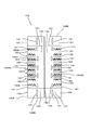
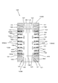
次に図3~図5を参照しつつ、清掃体100について説明する。清掃体100は、清掃対象の塵芥等の汚れを捕集する、汚れ捕集機能を有するシート状の清掃体である。図4、図5に示すように、清掃体100は、平面視で長方形状に形成されている。
この清掃体100は、一回使用を目安とした使い捨てタイプのものや、清掃対象の被清掃面から除去したごみや埃を保持しつつ複数回の使用を目安として交換を行う使い捨てタイプのものであってもよいし、或いは洗濯などを行ったうえで繰り返し使用することが可能なタイプのものであってもよい。
これらの積層された基部120、繊維集合体110GF、第2のシート体122は、いずれも清掃体100の長手方向Yに長尺状に延在している。
繊維集合体110GFは、後述する短冊片150とともに、汚れ捕集機能を有する刷毛部110を形成する。この繊維集合体110GFが、本発明に係る「繊維集合体」の一例である。この刷毛部110が本発明における「刷毛部」の一例である。
繊維110SFは熱可塑性繊維を一部に含み、それぞれの繊維110SFが融着(「溶着」ともいう)可能とされている。
繊維集合体110GFは、所定の繊維配向方向110Dにて並列に並べられるとともに、厚み方向Zに積層された複数の繊維110SFにより形成される。本発明の実施形態において、繊維配向方向110Dは、長手交差方向Xと概ね合致する。一方、繊維110SFは柔軟な素材であるため、容易に屈曲、変形される。よって、繊維110SFの繊維配向方向110Dとは、製品の設計上における繊維配向性のことを示すものである。
また、清掃時の掃き出し機能を向上させるためには、剛性の高い繊維110SF、すなわち繊度が高い繊維110SFを含む繊維集合体110GFを用いるのが好ましい。また、繊維集合体110GFは、捲縮繊維を有する構成されるのが好ましい。ここでいう捲縮繊維は、周知の捲縮処理が付与された繊維として構成され、繊維同士が絡み易い構造とされる。このような捲縮繊維を用いると、繊維集合体110GFが清掃体ホルダ200装着前の状態よりも嵩高となり、更に捲縮部分にごみを取り込み易い構造とされる。本構造は、特にトウ繊維から形成された捲縮繊維を用いることによって実現され得る。
基部120(第1のシート体121)および第2のシート体122を構成する不織布は、いずれも典型的には熱溶融性繊維(熱可塑性繊維)からなるシート状の不織布が使用されている。すなわち、これら基部120および第2のシート体122は、「不織布シート」とも称呼される。なお、清掃時の掃き出し機能を向上させるためには、剛性の高い不織布を用いるのが好ましい。
なお、この不織布は、ポリエチレン(PE)、ポリプロピレン(PP)、ポリエチレンテレフタレート(PET)等の合成繊維が使用される。また、不織布の形態としては、エアースルー法や、スパンボンド法により形成されたものが使用される。
一方、不織布以外であっても、布帛や、合成樹脂によるフィルム体などを使用することもできる。
なお、換言すると、保持空間130は、長手交差方向Xにおける一対の第1の接合部141同士の間における基部120の所定領域と、第2のシート体122の所定領域とにより形成される。
一方、本発明に係る接合部は、超音波溶着、縫製、ホットメルト接着剤などによる粘着剤にて形成することも可能である。
この短冊片150が、本発明に係る「短冊片」の一例である。
短冊片150は、第1の短冊片151と、第1の短冊片151よりも高い剛性を有する第2の短冊片152とを有する。なお、本発明に係る実施形態においては、第2の短冊片152には熱エンボス加工が施されている。
具体的には、第1の短冊片151の剛性は51.2(mm/25mm)であり、第2の短冊片152の剛性は67.6(mm/25mm)である。なお、この剛性の測定は、JIS/L1096のカンチレバー法で測定した。
第2の短冊片152は、清掃対象の塵芥を掻き出し可能な掻き出し部152Aを有する。
この第1の短冊片151が、本発明に係る「第1の短冊片」の一例である。この第2の短冊片152が、本発明に係る「第2の短冊片」の一例である。この掻き出し部152Aが、本発明に係る「掻き出し部」の一例である。
この高剛性領域152Bが、本発明に係る「高剛性領域」の一例である。
第1の短冊片151は、短冊片長手方向150Y上の端部である端部151Yと、短冊片長手交差方向X上の端部である端部151Xを有する。第2の短冊片152は、短冊片長手方向150Y上の端部である端部152Yと、短冊片長手交差方向X上の端部である端部152Xを有する。
そして、高剛性領域152Aは、短冊片長手方向150Yに延びるように形成されている。この結果、第2の短冊片152が、その短冊片長手方向Yに対して強化される。
すなわち、図6においては、高剛性領域152Bは、第2の短冊片152の全体に亘って設けられている。このような場合は、掻き出し部152Aは、第2の短冊片152の端部152X、端部152Yと一致する。
一方、図7においては、高剛性領域152Bは、第2の短冊片152の一部の領域に設けられる。このような場合、掻き出し部152Aは、第2の短冊片152の領域上における高剛性領域152Bの端部に設けられる。
また、第1の短冊片151と前記第2の短冊片152とは、交互に配置されている。
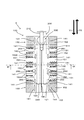
次に図9、図10を参照しつつ、清掃体ホルダ200と清掃体100の係合について説明する。図9に示すように、保持部材221はそれぞれ、保持空間130に挿入が可能とされている。保持部材221が挿入方向Y1に沿って保持空間130に挿入されることで、清掃体100が清掃体ホルダ200に保持される。一方、係合している清掃体ホルダ200と清掃体100とを分離するためには、清掃体ホルダ200を、引抜方向Y2に沿って保持空間130から引き抜く。
また、押え板270は、保持部材221とともに第2のシート体122を挟持する。
次に、本発明に係る清掃用具Aの作用につき、図11に基づき説明する。なお、図11においては、便宜上、切込み部150Aを直線として記載する。
ユーザが、清掃体100の長手交差方向X上の端部100Aを清掃対象に当接させる。すると、第2の短冊片152の掻き出し部152Aが、清掃対象に当接する。この状態で、ユーザが清掃用具Aの操作を継続することにより、塵芥が掻き出し部152Aにより掻き出される。この際、第2の短冊片152は高剛性領域152Bを有しているため、掻き出し作業に大きく支障を来すような変形をしない。この状態で、ユーザがさらに清掃用具Aの操作を継続すると、第1の短冊片151が清掃対象に当接し、変形される。さらにユーザが清掃用具Aの操作を継続すると、他の第2の短冊片152が清掃対象に当接する。このように、第1の短冊片151と第2の短冊片152が交互に形成されているため、複数の第2の短冊片152を連続して清掃対象に当接させることができる。なお、掻き出された塵芥は、繊維集合体110GFにより捕捉される。
よって、本発明に係る清掃用具Aにおいては、塵芥を効率的に掻き出すことが可能となる。従って、本発明に係る清掃用具Aは、清掃効率を向上させることができる。
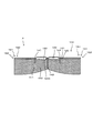
図12に基づき第1の変形例を説明する。なお、第1の変形例に係る清掃体101は、上述の実施形態における清掃体100に比して、保持空間130の構成が異なるものである。
すなわち、第1の変形例に係る清掃体101の保持空間130は、基部120を構成する第1のシート体121のみにて形成される。すなわち、第1のシート体121における所定の面同士を当接させ、接合シート領域121Aを形成する。この接合シート領域121Aにおける所定領域を溶着し、第2の接合部142を形成する。
これにより、長手方向Yに延びる空間である、保持空間130を形成することができる。
なお、この第1の変形例の場合、中央接合部140は、刷毛部110のみを接合することができる。この場合、刷毛部110と基部120とは、接着剤(図示せず)などにより接合することができる。
この第1の変形例に係る清掃体101であっても、第1の短冊片151と第2の短冊片152が形成されるため、上述の実施形態における清掃体100と同様の作用および効果を奏する。
図13に基づき第2の変形例を説明する。なお、第2の変形例に係る清掃体102は、上述の実施形態における清掃体100に比して、保持空間130の構成が異なるものである。
すなわち、第2の変形例に係る清掃体102の保持空間130は、基部120とは独立して形成される。第3のシート体123と、第4のシート体124を重ねる。そして、第3のシート123と第4のシート124における長手交差方向X上の両端部近傍の領域を、長手方向Y方向に沿って溶着し、第4の接合部144を形成する。
これにより、第3のシート123と第4のシート124との間に、長手方向Yに延びる空間である、保持空間130を形成することができる。
なお、この第2の変形例の場合、中央接合部140は、刷毛部110と基部120のみを接合する。第3のシート123は、接着剤などにより基部120と接合され、第5の接合部145を形成する。
この第2の変形例に係る清掃体101であっても、第1の短冊片151と第2の短冊片152が形成されるため、上述の実施形態における清掃体100と同様の作用および効果を奏する。
図14に基づき第3の変形例を説明する。なお、第3の変形例に係る清掃体103は、上述の実施形態における清掃体100に比して、保持空間130の構成が異なるものである。
すなわち、第3の変形例に係る清掃体103の保持空間130は、基部120とは独立して形成される。すなわち、第5のシート体125における所定の面同士を当接させ、接合シート領域125Aを形成する。この接合シート領域125Aにおける所定領域を溶着し、第6の接合部146を形成する。これにより、長手方向Yに延びる空間である、保持空間130を形成することができる。
なお、この第3の変形例の場合、中央接合部140は、刷毛部110と基部120のみを接合する。第5のシート125は、接着剤などにより基部120と接合され、第7の接合部147を形成する。
この第3の変形例に係る清掃体103であっても、第1の短冊片151と第2の短冊片152が形成されるため、上述の実施形態における清掃体100と同様の作用および効果を奏する。
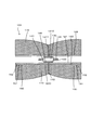
図15に基づき第4の変形例を説明する。なお、第4の変形例に係る清掃体104は、上述の実施形態における清掃体100に比して、基部120の一方の面120C側だけではなく、他方の面120D側にも刷毛部110が形成されているものである。
すなわち、基部120の一方の面120C側には繊維集合体110GFが重ねられる。基部120の他方面120Dには、第2のシート122と、繊維集合体110GFが重ねられる。すなわち、2つの繊維集合体110GFの間に、基部120と第2のシート体122が挟持された積層体となる。この積層体において、基部120および第2のシート体122における長手交差方向X上の端部領域が溶着され、一対の第8の接合部148を形成する。さらに、一対の第8の接合部148の間における領域において、積層体が溶着され、第9の接合部149を形成する。このようにして、清掃体104が形成される。
この第4の変形例に係る清掃体104であっても、第1の短冊片151と第2の短冊片152が形成されるため、上述の実施形態における清掃体100と同様の作用および効果を奏する。
さらに、基部120の他方の面120D側にも刷毛部110が形成されているため、ユーザの利便性が向上する。
図16に基づき第5の変形例を説明する。なお、第5の変形例に係る清掃体105は、上述の第1の変形例における清掃体101に比して、基部120の一方の面120C側だけではなく、他方の面120D側にも刷毛部110が形成されているものである。
すなわち、保持空間130を形成する第1のシート体121に、繊維集合体110GFが接合されるものである。基部120の他方の面120D側の繊維集合体110GFは、中央領域において溶着される。この中央領域における溶着箇所は、第10の接合部1410を形成する。この第10の接合部1410を有する繊維集合体110GFは、図示しない接着剤などにより、保持空間130を形成する第1のシート体121に接合する。このようにして、清掃体105が形成される。
この第5の変形例に係る清掃体105であっても、第1の短冊片151と第2の短冊片152が形成されるため、上述の実施形態における清掃体100と同様の作用および効果を奏する。
さらに、基部120の他方の面120D側にも刷毛部110が形成されているため、上述の第1の変形例に係る清掃体101よりも、ユーザの利便性が向上する。
図17に基づき第6の変形例を説明する。なお、第6の変形例に係る清掃体106は、上述の第2の変形例における清掃体102に比して、基部120の一方の面120C側だけではなく、他方の面120D側にも刷毛部110が形成されているものである。
すなわち、繊維集合体110と、第6のシート体126とを中央領域において溶着し、第11の接合部1411を形成する。そして、第6のシート体126における繊維集合体110が配置されていない面と、第4のシート体124とを接着剤などにより接合し、第12の接合部1412を形成する。このようにして、清掃体106が形成される。
この第6の変形例に係る清掃体106であっても、第1の短冊片151と第2の短冊片152が形成されるため、上述の実施形態における清掃体100と同様の作用および効果を奏する。
さらに、基部120の他方の面120D側にも刷毛部110が形成されているため、上述の第2の変形例に係る清掃体102よりも、ユーザの利便性が向上する。
図18に基づき第7の変形例を説明する。なお、第7の変形例に係る清掃体107は、上述の第3の変形例における清掃体103に比して、基部120の一方の面120C側だけではなく、他方の面120D側にも刷毛部110が形成されているものである。
すなわち、繊維集合体110と、第7のシート体127とを中央領域において溶着し、第13の接合部1413を形成する。そして、第7のシート体127における繊維集合体110が配置されていない面と、第5のシート体125とを接着剤などにより接合し、第14の接合部1414を形成する。このようにして、清掃体107が形成される。
この第7の変形例に係る清掃体107であっても、第1の短冊片151と第2の短冊片152が形成されるため、上述の実施形態における清掃体100と同様の作用および効果を奏する。
さらに、基部120の他方の面120D側にも刷毛部110が形成されているため、上述の第3の変形例に係る清掃体103よりも、ユーザの利便性が向上する。
図19に基づき第8の変形例を説明する。なお、第8の変形例に係る清掃体108は、上述の実施形態における清掃体100に比して、清掃体長手交差方向X上の端部100Aにおける中央領域100ACに第2の短冊片152が形成されているものである。この際、第1の短冊片151は、清掃体長手交差方向端部100Aと、清掃体長手方向端部100Bとが交差する領域に配置される。
この第8の変形例に係る清掃体108であっても、第1の短冊片151と第2の短冊片152が形成されるため、上述の実施形態における清掃体100と基本的には同様の作用および効果を奏する。一方、第8の変形例に係る清掃体108は、実施形態に係る清掃体100に比して第2の短冊片152の配置位置が異なる。よって、特定の清掃対象に対しては、実施形態に係る清掃体100よりも清掃効率を向上させることが可能となる。
図20に基づき第9の変形例を説明する。なお、第9の変形例に係る清掃体109は、上述の実施形態における清掃体100に比して、清掃体長手交差方向X上の端部100Aにおける中央領域100ACに第1の短冊片151が形成されているものである。この際、第2の短冊片152は、清掃体長手交差方向端部100Aと、清掃体長手方向端部100Bとが交差する領域に配置される。
この第9の変形例に係る清掃体109であっても、第1の短冊片151と第2の短冊片152が形成されるため、上述の実施形態における清掃体100と基本的には同様の作用および効果を奏する。一方、第9の変形例に係る清掃体109は、実施形態に係る清掃体100に比して第2の短冊片152の配置位置が異なる。よって、特定の清掃対象に対しては、実施形態に係る清掃体100よりも清掃効率を向上させることが可能となる。
図21に基づき第10の変形例を説明する。なお、第10の変形例に係る清掃体110は、上述の実施形態における清掃体100に比して、清掃体長手方向Y上の端部100Bに、第1の短冊片151と第2の短冊片152とが交互に配置されているものである。
この第10の変形例に係る清掃体110であっても、第1の短冊片151と第2の短冊片152が形成されるため、上述の実施形態における清掃体100と基本的には同様の作用および効果を奏する。一方、第10の変形例に係る清掃体110は、実施形態に係る清掃体100に比して第2の短冊片152の配置位置が異なる。よって、特定の清掃対象に対しては、実施形態に係る清掃体100よりも清掃効率を向上させることが可能となる。
図22に基づき第11の変形例を説明する。なお、第11の変形例に係る清掃体111は、上述の実施形態における清掃体100に比して、清掃体長手方向Y上の端部100Bにおける中央領域100BCに第2の短冊片152が形成されているものである。この際、第1の短冊片151は、清掃体長手交差方向端部100Aと、清掃体長手方向端部100Bとが交差する領域に配置される。
この第11の変形例に係る清掃体111であっても、第1の短冊片151と第2の短冊片152が形成されるため、上述の実施形態における清掃体100と基本的には同様の作用および効果を奏する。一方、第11の変形例に係る清掃体111は、実施形態に係る清掃体100に比して第2の短冊片152の配置位置が異なる。よって、特定の清掃対象に対しては、実施形態に係る清掃体100よりも清掃効率を向上させることが可能となる。
図23に基づき第12の変形例を説明する。なお、第12の変形例に係る清掃体112は、上述の実施形態における清掃体100に比して、清掃体長手方向Y上の端部100Bにおける中央領域100BCに第1の短冊片151が形成されているものである。この際、第2の短冊片152は、清掃体長手交差方向端部100Aと、清掃体長手方向端部100Bとが交差する領域に配置される。
この第12の変形例に係る清掃体112であっても、第1の短冊片151と第2の短冊片152が形成されるため、上述の実施形態における清掃体100と基本的には同様の作用および効果を奏する。一方、第12の変形例に係る清掃体112は、実施形態に係る清掃体100に比して第2の短冊片152の配置位置が異なる。よって、特定の清掃対象に対しては、実施形態に係る清掃体100よりも清掃効率を向上させることが可能となる。
清掃具Aは、本発明に係る「清掃具」の一例である。清掃体100、101、102、103、104、105、106、107、108、109、110、111、112は、本発明に係る「清掃シート」の一例である。清掃体ホルダ200は、本発明に係る「保持具」の一例である。清掃体長手方向Yは、本発明に係る「清掃シート長手方向」の一例である。清掃体長手交差方向Xは、本発明に係る「清掃シート長手交差方向」の一例である。清掃体保持部220は、本発明に係る「保持部」の一例である。ハンドル部210は、本発明に係る「把持部」の一例である。刷毛部110は、本発明に係る「刷毛部」の一例である。基部120は、本発明に係る「基部」の一例である。保持空間130は、本発明に係る「挿入部」の一例である。短冊片150は、本発明に係る「短冊片」の一例である。第1の短冊片151は、本発明に係る「第1の短冊片」の一例である。第2の短冊片152は、本発明に係る「第2の短冊片」の一例である。掻き出し部152Aは、本発明に係る「掻き出し部」の一例である。高剛性領域152Bは、本発明に係る「高剛性領域」の一例である。短冊片長手方向150Yは、本発明に係る「短冊片長手方向」の一例である。短冊片長手交差方向150Xは、本発明に係る「短冊片長手交差方向」の一例である。
第1のシート121は、本発明に係る「第1のシート体」の一例である。第2のシート体122は、本発明に係る「第2のシート体」の一例である。第3のシート体123は、本発明に係る「第3のシート体」の一例である。第4のシート体124は、本発明に係る「第4のシート体」の一例である。第5のシート体125は、本発明に係る「第5のシート体」の一例である。一方の面120Aは、本発明に係る「一方の側」の一例である。他方の面120Dは、本発明に係る「他方の側」の一例である。
(態様1)
清掃シートと、前記清掃シートを保持する保持具とを有する清掃具において、
前記清掃シートは、当該清掃シートに前記保持具を挿入する方向によって規定される清掃シート長手方向と、当該清掃シート長手方向と交差する方向によって規定される清掃シート長手交差方向の双方に延在するように構成され、
前記保持具は、前記清掃シートを保持するための保持部と、前記保持部に連結されてユーザに把持される把持部とを有し、
前記清掃シートは、清掃対象を清掃可能に構成された刷毛部と、前記刷毛部が接続される基部と、当該基部に形成されて、前記保持部が挿入される挿入部とを有し、
前記刷毛部は、短冊状のシートにより形成される複数の短冊片を有し、
当該短冊片は、第1の短冊片と、当該第1の短冊片よりも高い剛性を有する第2の短冊片とを有し、
当該第2の短冊片は、前記清掃対象の塵芥を掻き出し可能な掻き出し部を有することを特徴とする清掃具。
(態様2)
態様1に記載された清掃具において、
前記第2の短冊片は、高剛性領域を有することを特徴とする清掃具。
(態様3)
態様2に記載された清掃具において、
前記短冊片は、当該短冊片が延びる方向によって規定される短冊片長手方向と、当該短冊片長手方向と交差する方向によって規定される短冊片長手交差方向の双方に延在するように構成され、
前記高剛性領域は、前記短冊片長手方向に延びるように形成されていることを特徴とする清掃具。
(態様4)
態様1~3のいずれか1項に記載された清掃具において、
前記第2の短冊片は、前記清掃シート長手方向上の端部領域に設けられていることを特徴とする清掃具。
(態様5)
態様1~3のいずれか1項に記載された清掃具において、
前記前記第2の短冊片は、前記清掃シート長手方向上の中央領域に設けられていることを特徴とする清掃具。
(態様6)
態様1~3のいずれか1項に記載された清掃具において、
前記第2の短冊片は、前記清掃シート長手交差方向上の端部領域に設けられていることを特徴とする清掃具。
(態様7)
態様1~3のいずれか1項に記載された清掃具において、
前記第2の短冊片は、前記清掃シート長手交差方向上の中央領域に設けられていることを特徴とする清掃具。
(態様8)
態様1~7のいずれか1項に記載された清掃具において、
前記第1の短冊片と前記第2の短冊片とは、交互に配置されていることを特徴とする清掃具。
(態様9)
態様1~8のいずれか1項に記載された清掃具において、
前記基部は、第1のシート体により形成されていることを特徴とする清掃具。
(態様10)
態様9に記載された清掃具において、
前記基部は、前記第1のシート体の端部に設けられた複数の切込み部を有し、
前記短冊片は、前記複数の切込み部同士の間に形成されることを特徴とする清掃具。
(態様11)
態様9または10のいずれか1項に記載された清掃具において、
前記第1のシート体と重ねられる第2のシート体を有し、
前記挿入部は、前記第1のシート体と、前記第2とシート体との間に形成されることを特徴とする清掃具。
(態様12)
態様9または10のいずれか1項に記載された清掃具において、
前記挿入部は、前記第1のシート体における所定の面同士を当接させ接合シート領域を形成するとともに、当該接合シート領域における前記所定の面同士を接合することにより形成されていることを特徴とする清掃具。
(態様13)
態様9または10のいずれか1項に記載された清掃具において、
前記第1のシート体に重ねられる第3のシート体と、当該第3のシート体に重ねられる第4のシート体とを有し、
前記挿入部は、前記第3のシート体と、前記第4とシート体との間に形成されることを特徴とする清掃具。
(態様14)
態様9または10のいずれか1項に記載された清掃具において、
前記第1のシート体に重ねられる第5のシート体を有し、
前記挿入部は、前記第5のシート体における所定の面同士を当接させ接合シート領域を形成するとともに、当該接合シート領域における前記所定の面同士を接合することにより形成されていることを特徴とする清掃具。
(態様15)
態様1~14のいずれか1項に記載された清掃具において、
前記刷毛部は、前記基部の一方の側に設けられていることを特徴とする清掃具。
(態様16)
態様1~14のいずれか1項に記載された清掃具において、
前記刷毛部は、前記基部の一方の側および他方の側に設けられていることを特徴とする清掃具。
(態様17)
態様1~16のいずれか1項に記載された清掃具において、
前記掻き出し部は、前記高剛性領域の端部に設けられることを特徴とする清掃具。
(態様18)
態様1~17のいずれか1項に記載された清掃具において、
前記第2の短冊片は、前記清掃体の清掃体長手交差方向上の端部と、前記清掃体の前記清掃体長手方向端部とが交差する領域に配置されることを特徴とする清掃具。
100、101、102、103、104、105、106、107、108、109、110、111、112 清掃シート(清掃体)
100B 端部
100A 端部
100BC 中央領域
100AC 中央領域
110 刷毛部
110GF 繊維集合体
110GF1 第1の繊維集合体
110GF2 第2の繊維集合体
110SF 繊維
110SFA 接続端部
110SFB 開放端部
110D 繊維配向方向
111 第1の刷毛部
112 第2の刷毛部
112A 端部
120 基部
120A 長手方向上の端部
120B 長手交差方向上の端部
120C 一方の面(一方の側)
120D 他方の面(他方の側)
121 第1のシート体
121A 接合シート領域
121S 短冊片
122 第2のシート体
122S 短冊片
123 第3のシート体
124 第4のシート体
125 第5のシート体
126 第6のシート体
127 第7のシート体
130 挿入部
131 開口部
140 全層接合部
141 第1の接合部
142 第2の接合部
143 第3の接合部
144 第4の接合部
145 第5の接合部
146 第6の接合部
147 第7の接合部
148 第8の接合部
149 第9の接合部
1410 第10の接合部
1411 第11の接合部
1412 第12の接合部
1413 第13の接合部
1414 第14の接合部
150 短冊片
150A 切込み部
150Y 短冊片長手方向
150X 短冊片長手交差方向
151 第1の短冊片
151Y 端部
151X 端部
152 第2の短冊片
152A 掻き出し部
152B 高剛性領域
152Y 端部
152X 端部
200 保持具(清掃体ホルダ)
210 ハンドル部(把持部)
211 ハンドル
212 ハンドル接合部
220 清掃体保持部(保持部)
221 保持部材
230 連接部
240 先端部
250 中間部
260 凸部
261 第1の凸部
262 第2の凸部
270 押え板
Y 清掃体長手方向
X 清掃体長手交差方向
Z 清掃シート厚み方向
Claims (16)
- 清掃シートと、当該清掃シートを保持する保持具とを有する清掃具において、
前記清掃シートは、当該清掃シートに前記保持具を挿入する方向によって規定される清掃シート長手方向と、当該清掃シート長手方向と交差する方向によって規定される清掃シート長手交差方向の双方に延在するように構成され、
前記保持具は、前記清掃シートを保持するための保持部と、当該保持部に連結されてユーザに把持される把持部とを有し、
前記清掃シートは、清掃対象を清掃可能に構成された刷毛部と、当該刷毛部が接続される基部と、当該基部に形成されて前記保持部が挿入される挿入部とを有し、
前記刷毛部は、短冊状のシートにより形成される複数の短冊片を有し、
当該短冊片は、第1の短冊片と、当該第1の短冊片よりも高い剛性を有する第2の短冊片とを有し、
当該第2の短冊片は、前記清掃対象の塵芥を掻き出し可能な掻き出し部を有することを特徴とする清掃具。 - 請求項1に記載された清掃具において、
前記第2の短冊片は、高剛性領域を有することを特徴とする清掃具。 - 請求項2に記載された清掃具において、
前記短冊片は、当該短冊片が延びる方向によって規定される短冊片長手方向と、当該短冊片長手方向と交差する方向によって規定される短冊片長手交差方向の双方に延在するように構成され、
前記高剛性領域は、前記短冊片長手方向に延びるように形成されていることを特徴とする清掃具。 - 請求項1~3のいずれか1項に記載された清掃具において、
前記第2の短冊片は、前記清掃シート長手方向上の端部領域に設けられていることを特徴とする清掃具。 - 請求項1~3のいずれか1項に記載された清掃具において、
前記前記第2の短冊片は、前記清掃シート長手方向上の中央領域に設けられていることを特徴とする清掃具。 - 請求項1~3のいずれか1項に記載された清掃具において、
前記第2の短冊片は、前記清掃シート長手交差方向上の端部領域に設けられていることを特徴とする清掃具。 - 請求項1~3のいずれか1項に記載された清掃具において、
前記第2の短冊片は、前記清掃シート長手交差方向上の中央領域に設けられていることを特徴とする清掃具。 - 請求項1~7のいずれか1項に記載された清掃具において、
前記第1の短冊片と前記第2の短冊片とは、交互に配置されていることを特徴とする清掃具。 - 請求項1~8のいずれか1項に記載された清掃具において、
前記基部は、第1のシート体により形成されていることを特徴とする清掃具。 - 請求項9に記載された清掃具において、
前記基部は、前記第1のシート体の端部に設けられた複数の切込み部を有し、
前記短冊片は、前記複数の切込み部同士の間に形成されることを特徴とする清掃具。 - 請求項9または10のいずれか1項に記載された清掃具において、
前記第1のシート体と重ねられる第2のシート体を有し、
前記挿入部は、前記第1のシート体と、前記第2とシート体との間に形成されることを特徴とする清掃具。 - 請求項9または10のいずれか1項に記載された清掃具において、
前記挿入部は、前記第1のシート体における所定の面同士を当接させ接合シート領域を形成するとともに、当該接合シート領域における前記所定の面同士を接合することにより形成されていることを特徴とする清掃具。 - 請求項9または10のいずれか1項に記載された清掃具において、
前記第1のシート体に重ねられる第3のシート体と、当該第3のシート体に重ねられる第4のシート体とを有し、
前記挿入部は、前記第3のシート体と、前記第4とシート体との間に形成されることを特徴とする清掃具。 - 請求項9または10のいずれか1項に記載された清掃具において、
前記第1のシート体に重ねられる第5のシート体を有し、
前記挿入部は、前記第5のシート体における所定の面同士を当接させ接合シート領域を形成するとともに、当該接合シート領域における前記所定の面同士を接合することにより形成されていることを特徴とする清掃具。 - 請求項1~14のいずれか1項に記載された清掃具において、
前記刷毛部は、前記基部の一方の側に設けられていることを特徴とする清掃具。 - 請求項1~14のいずれか1項に記載された清掃具において、
前記刷毛部は、前記基部の一方の側および当該一方の側と対向する側である他方の側に設けられていることを特徴とする清掃具。
Priority Applications (4)
| Application Number | Priority Date | Filing Date | Title |
|---|---|---|---|
| EP14749282.1A EP2954825B1 (en) | 2013-02-07 | 2014-01-24 | Cleaning tool |
| CN201480007793.8A CN104981191B (zh) | 2013-02-07 | 2014-01-24 | 清扫工具 |
| KR1020157020729A KR102175025B1 (ko) | 2013-02-07 | 2014-01-24 | 청소구 |
| US14/766,438 US10383503B2 (en) | 2013-02-07 | 2014-01-24 | Cleaning tool |
Applications Claiming Priority (2)
| Application Number | Priority Date | Filing Date | Title |
|---|---|---|---|
| JP2013022762A JP6323981B2 (ja) | 2013-02-07 | 2013-02-07 | 清掃具 |
| JP2013-022762 | 2013-02-07 |
Publications (1)
| Publication Number | Publication Date |
|---|---|
| WO2014123012A1 true WO2014123012A1 (ja) | 2014-08-14 |
Family
ID=51299609
Family Applications (1)
| Application Number | Title | Priority Date | Filing Date |
|---|---|---|---|
| PCT/JP2014/051587 Ceased WO2014123012A1 (ja) | 2013-02-07 | 2014-01-24 | 清掃具 |
Country Status (7)
| Country | Link |
|---|---|
| US (1) | US10383503B2 (ja) |
| EP (1) | EP2954825B1 (ja) |
| JP (1) | JP6323981B2 (ja) |
| KR (1) | KR102175025B1 (ja) |
| CN (1) | CN104981191B (ja) |
| TW (1) | TWI618520B (ja) |
| WO (1) | WO2014123012A1 (ja) |
Cited By (2)
| Publication number | Priority date | Publication date | Assignee | Title |
|---|---|---|---|---|
| CN107427178A (zh) * | 2015-03-12 | 2017-12-01 | 尤妮佳股份有限公司 | 清扫片材及清扫用具 |
| WO2024120965A1 (en) * | 2022-12-07 | 2024-06-13 | Carl Freudenberg Kg | Cleaning article |
Families Citing this family (7)
| Publication number | Priority date | Publication date | Assignee | Title |
|---|---|---|---|---|
| US10694915B2 (en) * | 2017-04-06 | 2020-06-30 | The Procter & Gamble Company | Sheet with tow fiber and movable strips |
| US11253128B2 (en) * | 2017-09-11 | 2022-02-22 | The Procter & Gamble Company | Cleaning article with differential pitch tow tufts |
| US11950737B2 (en) | 2017-09-11 | 2024-04-09 | The Procter & Gamble Company | Cleaning article with irregularly spaced tow tufts |
| CN121221012A (zh) * | 2018-04-10 | 2025-12-30 | 山田菊夫 | 清扫片 |
| WO2019240280A1 (ja) * | 2018-06-15 | 2019-12-19 | ユニ・チャーム株式会社 | 清掃シート、及び清掃シート用資材を連続で製造する方法 |
| USD923895S1 (en) * | 2019-03-05 | 2021-06-29 | Tyroler Ltd. | Rubber mop |
| JP7002490B2 (ja) * | 2019-03-08 | 2022-01-20 | ユニ・チャーム株式会社 | 清掃シート |
Citations (5)
| Publication number | Priority date | Publication date | Assignee | Title |
|---|---|---|---|---|
| JP2002369783A (ja) * | 2000-07-10 | 2002-12-24 | Uni Charm Corp | 清掃用物品 |
| JP2003265389A (ja) * | 2001-02-23 | 2003-09-24 | Uni Charm Corp | 清掃用物品 |
| JP2007137566A (ja) | 2005-11-16 | 2007-06-07 | Canon Inc | 画像記録装置 |
| JP2011156295A (ja) * | 2010-02-03 | 2011-08-18 | Unicharm Corp | 清掃用具、清掃体 |
| JP2012147993A (ja) * | 2011-01-20 | 2012-08-09 | Unicharm Corp | 清掃用具、清掃用物品 |
Family Cites Families (12)
| Publication number | Priority date | Publication date | Assignee | Title |
|---|---|---|---|---|
| SG64435A1 (en) * | 1996-09-27 | 1999-04-27 | Uni Charm Corp | Disposable wiper sheet and method for producing the same |
| CN2712262Y (zh) * | 2004-03-29 | 2005-07-27 | 富雅乐企业股份有限公司 | 擦拭用布 |
| JP4004508B2 (ja) * | 2005-02-23 | 2007-11-07 | 山崎産業株式会社 | 払拭材 |
| JP4675218B2 (ja) * | 2005-11-15 | 2011-04-20 | 花王株式会社 | 清掃用物品及びその製造方法 |
| JP4845525B2 (ja) * | 2006-02-08 | 2011-12-28 | ユニ・チャーム株式会社 | 清掃体及び清掃用具 |
| JP4738311B2 (ja) * | 2006-06-01 | 2011-08-03 | 花王株式会社 | 清掃用物品及びその製造方法 |
| JP4709105B2 (ja) * | 2006-09-12 | 2011-06-22 | ユニ・チャーム株式会社 | 清掃体及び清掃用具 |
| JP4934464B2 (ja) | 2007-03-05 | 2012-05-16 | 大日本印刷株式会社 | 清掃用具 |
| JP5048375B2 (ja) | 2007-03-30 | 2012-10-17 | ユニ・チャーム株式会社 | 清掃体及び清掃用具 |
| JP5171348B2 (ja) * | 2008-03-31 | 2013-03-27 | ユニ・チャーム株式会社 | 清掃用具、清掃体 |
| JP5171347B2 (ja) * | 2008-03-31 | 2013-03-27 | ユニ・チャーム株式会社 | 清掃用具 |
| JP3148559U (ja) * | 2008-12-05 | 2009-02-19 | 憲子 藤巻 | 埃取り掃除具 |
-
2013
- 2013-02-07 JP JP2013022762A patent/JP6323981B2/ja active Active
-
2014
- 2014-01-24 KR KR1020157020729A patent/KR102175025B1/ko active Active
- 2014-01-24 US US14/766,438 patent/US10383503B2/en active Active
- 2014-01-24 EP EP14749282.1A patent/EP2954825B1/en active Active
- 2014-01-24 CN CN201480007793.8A patent/CN104981191B/zh active Active
- 2014-01-24 WO PCT/JP2014/051587 patent/WO2014123012A1/ja not_active Ceased
- 2014-02-07 TW TW103104114A patent/TWI618520B/zh active
Patent Citations (5)
| Publication number | Priority date | Publication date | Assignee | Title |
|---|---|---|---|---|
| JP2002369783A (ja) * | 2000-07-10 | 2002-12-24 | Uni Charm Corp | 清掃用物品 |
| JP2003265389A (ja) * | 2001-02-23 | 2003-09-24 | Uni Charm Corp | 清掃用物品 |
| JP2007137566A (ja) | 2005-11-16 | 2007-06-07 | Canon Inc | 画像記録装置 |
| JP2011156295A (ja) * | 2010-02-03 | 2011-08-18 | Unicharm Corp | 清掃用具、清掃体 |
| JP2012147993A (ja) * | 2011-01-20 | 2012-08-09 | Unicharm Corp | 清掃用具、清掃用物品 |
Non-Patent Citations (1)
| Title |
|---|
| See also references of EP2954825A4 |
Cited By (3)
| Publication number | Priority date | Publication date | Assignee | Title |
|---|---|---|---|---|
| CN107427178A (zh) * | 2015-03-12 | 2017-12-01 | 尤妮佳股份有限公司 | 清扫片材及清扫用具 |
| EP3269285A4 (en) * | 2015-03-12 | 2018-05-30 | Uni-Charm Corporation | Cleaning sheet and cleaning instrument |
| WO2024120965A1 (en) * | 2022-12-07 | 2024-06-13 | Carl Freudenberg Kg | Cleaning article |
Also Published As
| Publication number | Publication date |
|---|---|
| US10383503B2 (en) | 2019-08-20 |
| EP2954825A1 (en) | 2015-12-16 |
| TWI618520B (zh) | 2018-03-21 |
| KR20150114952A (ko) | 2015-10-13 |
| JP6323981B2 (ja) | 2018-05-16 |
| CN104981191B (zh) | 2017-07-28 |
| EP2954825B1 (en) | 2020-01-15 |
| US20150359404A1 (en) | 2015-12-17 |
| EP2954825A4 (en) | 2016-09-07 |
| CN104981191A (zh) | 2015-10-14 |
| JP2014150975A (ja) | 2014-08-25 |
| KR102175025B1 (ko) | 2020-11-05 |
| TW201507677A (zh) | 2015-03-01 |
Similar Documents
| Publication | Publication Date | Title |
|---|---|---|
| JP6323981B2 (ja) | 清掃具 | |
| CN101980646A (zh) | 清扫用具、清扫体 | |
| JP6323980B2 (ja) | 清掃具 | |
| JP6228366B2 (ja) | 清掃具 | |
| JP6126398B2 (ja) | 清掃具 | |
| JP6208949B2 (ja) | 清掃具 | |
| JP6228407B2 (ja) | 清掃用具および清掃用具の製造方法 | |
| JP5637875B2 (ja) | 清掃用具、清掃用物品 | |
| JP6346586B2 (ja) | 清掃具 | |
| JP6239828B2 (ja) | 清掃具 | |
| JP6126399B2 (ja) | 清掃具および清掃シートの製造方法 | |
| JP5973930B2 (ja) | 清掃具 | |
| JP6126397B2 (ja) | 清掃具 | |
| JP6195863B2 (ja) | 清掃具の製造方法および清掃シートの製造方法 | |
| JP5968245B2 (ja) | 清掃具および清掃シートの製造方法 | |
| JP6060000B2 (ja) | 清掃具 | |
| JP2014150965A5 (ja) | ||
| JP2014150966A5 (ja) |
Legal Events
| Date | Code | Title | Description |
|---|---|---|---|
| 121 | Ep: the epo has been informed by wipo that ep was designated in this application |
Ref document number: 14749282 Country of ref document: EP Kind code of ref document: A1 |
|
| ENP | Entry into the national phase |
Ref document number: 20157020729 Country of ref document: KR Kind code of ref document: A |
|
| WWE | Wipo information: entry into national phase |
Ref document number: 14766438 Country of ref document: US |
|
| NENP | Non-entry into the national phase |
Ref country code: DE |
|
| WWE | Wipo information: entry into national phase |
Ref document number: 2014749282 Country of ref document: EP |
|
| WWE | Wipo information: entry into national phase |
Ref document number: IDP00201505393 Country of ref document: ID |