WO2014123013A1 - Outil de nettoyage - Google Patents
Outil de nettoyage Download PDFInfo
- Publication number
- WO2014123013A1 WO2014123013A1 PCT/JP2014/051588 JP2014051588W WO2014123013A1 WO 2014123013 A1 WO2014123013 A1 WO 2014123013A1 JP 2014051588 W JP2014051588 W JP 2014051588W WO 2014123013 A1 WO2014123013 A1 WO 2014123013A1
- Authority
- WO
- WIPO (PCT)
- Prior art keywords
- region
- cleaning
- sheet
- holding
- cleaning tool
- Prior art date
- Legal status (The legal status is an assumption and is not a legal conclusion. Google has not performed a legal analysis and makes no representation as to the accuracy of the status listed.)
- Ceased
Links
Images







Classifications
-
- A—HUMAN NECESSITIES
- A47—FURNITURE; DOMESTIC ARTICLES OR APPLIANCES; COFFEE MILLS; SPICE MILLS; SUCTION CLEANERS IN GENERAL
- A47L—DOMESTIC WASHING OR CLEANING; SUCTION CLEANERS IN GENERAL
- A47L13/00—Implements for cleaning floors, carpets, furniture, walls, or wall coverings
- A47L13/10—Scrubbing; Scouring; Cleaning; Polishing
- A47L13/42—Details
- A47L13/46—Securing scouring or polishing cloths or sponges to the handles by gripping means, tongs, or the like
-
- A—HUMAN NECESSITIES
- A47—FURNITURE; DOMESTIC ARTICLES OR APPLIANCES; COFFEE MILLS; SPICE MILLS; SUCTION CLEANERS IN GENERAL
- A47L—DOMESTIC WASHING OR CLEANING; SUCTION CLEANERS IN GENERAL
- A47L13/00—Implements for cleaning floors, carpets, furniture, walls, or wall coverings
- A47L13/10—Scrubbing; Scouring; Cleaning; Polishing
- A47L13/16—Cloths; Pads; Sponges
-
- A—HUMAN NECESSITIES
- A47—FURNITURE; DOMESTIC ARTICLES OR APPLIANCES; COFFEE MILLS; SPICE MILLS; SUCTION CLEANERS IN GENERAL
- A47L—DOMESTIC WASHING OR CLEANING; SUCTION CLEANERS IN GENERAL
- A47L13/00—Implements for cleaning floors, carpets, furniture, walls, or wall coverings
- A47L13/10—Scrubbing; Scouring; Cleaning; Polishing
- A47L13/20—Mops
-
- A—HUMAN NECESSITIES
- A47—FURNITURE; DOMESTIC ARTICLES OR APPLIANCES; COFFEE MILLS; SPICE MILLS; SUCTION CLEANERS IN GENERAL
- A47L—DOMESTIC WASHING OR CLEANING; SUCTION CLEANERS IN GENERAL
- A47L13/00—Implements for cleaning floors, carpets, furniture, walls, or wall coverings
- A47L13/10—Scrubbing; Scouring; Cleaning; Polishing
- A47L13/20—Mops
- A47L13/24—Frames for mops; Mop heads
-
- A—HUMAN NECESSITIES
- A47—FURNITURE; DOMESTIC ARTICLES OR APPLIANCES; COFFEE MILLS; SPICE MILLS; SUCTION CLEANERS IN GENERAL
- A47L—DOMESTIC WASHING OR CLEANING; SUCTION CLEANERS IN GENERAL
- A47L13/00—Implements for cleaning floors, carpets, furniture, walls, or wall coverings
- A47L13/10—Scrubbing; Scouring; Cleaning; Polishing
- A47L13/38—Other dusting implements
Definitions
- the present invention relates to a cleaning tool for cleaning an object to be cleaned.
- Japanese Patent Application Laid-Open No. 2011-041828 describes a cleaning tool including a sheet-like cleaning body and a cleaning body holder for holding the cleaning body.
- the cleaning body is formed by laminating a plurality of sheets and a fiber assembly.
- the cleaning body holder has a pair of bifurcated holding plates.
- the holding plate is a long flat plate, and the two holding plates are arranged on the same plane.
- a cleaning body is hold
- an object of this invention is to provide the cleaning tool which can utilize a cleaning sheet
- the cleaning tool includes a cleaning sheet and a holding tool for holding the cleaning sheet, and the cleaning tool is disposed on the cleaning sheet.
- the cleaning sheet has a longitudinal direction that is a direction in which the holder is inserted and a longitudinal intersecting direction that is a direction that intersects the longitudinal direction, and the cleaning sheet includes a first region that includes a sheet member, and a second region that includes a sheet member.
- An insertion portion in which an insertion space continuous in the longitudinal direction is formed so that the holder is inserted between the first region and the second region.
- a holding unit that is inserted into the insertion space and holds the cleaning sheet, a tension applying unit that is provided in the holding unit and applies a predetermined tension to the second region of the cleaning sheet, and a user connected to the holding unit To grip
- the second region of the cleaning sheet is applied with tension by the tension applying unit of the holding unit in a state where the holding unit of the holding tool is inserted into the insertion unit of the cleaning sheet.
- the tension member is formed, and the sheet member in the longitudinal crossing direction in the tension portion is moved in the direction in which the first region is arranged.
- tensile_strength provision part is tension
- tensile_strength provision part which provides tension
- a second tension applying unit that applies
- the said 2nd tension provision part is arrange
- the tension portion is formed from the second tension applying portion to the first tension applying portion.
- the sheet member is configured with a high-rigidity region having high rigidity and a low-rigidity region having lower rigidity than the high-rigidity region.
- region extends continuously in the said longitudinal cross direction.
- the cleaning tool which concerns on this invention, it has a 1st junction part for connecting the said 1st area
- the said highly rigid part is the 2nd junction part which welded the said sheet
- the said cleaning sheet has a fiber assembly,
- the second joint portion connects a part of the fiber assembly and the sheet member.
- the cleaning tool concerning the present invention, it is formed in the insertion direction which is a direction parallel to the longitudinal direction, the drawing direction which is the direction opposite to the insertion direction, and the side surface of the extension part.
- a convex portion, and the convex portion includes an insertion side region provided on the insertion direction side, a pulling side region provided on the pulling direction side, the insertion side region, and the pulling side region.
- An insertion start point which is a point at which the insertion side region first contacts the joint in the state where the holder is inserted into the insertion portion.
- an insertion end point which is the point where the insertion-side region finally comes into contact with the joint portion in a state where the holder is inserted into the insertion portion, and the insertion start point and the insertion end point.
- the first virtual straight line and the insertion passing through the insertion start point A second imaginary straight line that is parallel to the direction, a first angle formed by the first imaginary straight line and the second imaginary straight line, and a state in which the holder is pulled out from the insertion portion.
- a drawing start point which is a point at which the drawing side region first comes into contact with the joint portion, and a drawing point, at which the drawing side region finally comes into contact with the joint portion in a state in which the holder is pulled out from the insertion portion.
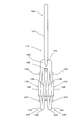
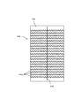
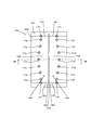
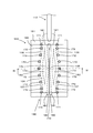
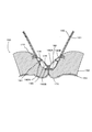
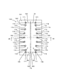
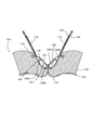
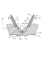
- FIG. 1 It is a perspective view which shows the whole structure of the cleaning tool which concerns on embodiment of this invention. It is a top view of a cleaning holder. It is a side view of a cleaning holder. It is a disassembled perspective view which shows each component of a cleaning body. It is a top view of the cleaning body seen from the cleaning surface side. It is a top view of the cleaning body seen from the holding surface side. It is sectional drawing in the VII-VII line of FIG. It is a figure which shows the state which engaged the cleaning holder with the cleaning body. It is sectional drawing in the IX-IX line of FIG. It is a top view equivalent to FIG. 6 in the 1st modification of this invention. It is sectional drawing equivalent to FIG.
- the cleaning object to be cleaned using the cleaning tool 100 is a surface to be cleaned (floor surface, wall surface, window, ceiling surface, outer wall surface, furniture, etc.) such as a single-family house, condominium, building, factory, vehicle, etc. Surface, clothes, curtains, bedding, lighting, home appliances, etc.) and surfaces to be cleaned in each component of the human body.
- surfaces to be cleaned may be configured as a flat surface, or may be configured as a curved surface, an uneven surface, or a step surface.
- the cleaning tool 100 includes a cleaning body holder 110 and a cleaning body 140.
- the cleaning body holder 110 is detachably attached to the cleaning body 140 and is configured to hold the cleaning body 140.
- the cleaning tool 100, the cleaning body holder 110, and the cleaning body 140 are implementation configuration examples corresponding to “cleaning tool”, “holding tool”, and “cleaning sheet” in the present invention, respectively.
- the cleaning tool 100 has a longitudinal direction Y and a longitudinal intersecting direction X that is a direction intersecting the longitudinal direction Y.
- the longitudinal direction Y is a direction parallel to an insertion direction Y1 that is a direction in which the cleaning body holder 110 is attached to the cleaning body 140, and a pulling direction Y2 that is a direction in which the cleaning body holder 110 is pulled out from the cleaning body 140.
- the longitudinal direction Y, the longitudinal cross direction X, the insertion direction Y1, and the drawing direction Y2 are implementation examples corresponding to the “longitudinal direction”, “longitudinal crossing direction”, “insertion direction”, and “pulling direction” in the present invention.
- the cleaning body holder 110 is mainly composed of a handle part 120 and a cleaning body holding part 130.
- the handle portion 120 is a member that is formed in a long shape and is held by the user during cleaning.
- the handle part 120 has a handle 121 and a joint part 122.
- the joining part 122 is joined to the base part 132 of the cleaning body holding part 130.
- the handle 121 is formed in a long shape extending from the joint portion 122.
- This handle portion 120 is an implementation configuration example corresponding to the “gripping portion” in the present invention.
- the upper side and the lower side in FIG. 2 are referred to as the right side and the left side of the cleaning body holder 110. 3 are referred to as the upper side and the lower side of the cleaning body holder 110, respectively.
- the cleaning body holding part 130 is a member that is molded of a resin material and holds the cleaning sheet 140.
- the cleaning body holding part 130 is mainly composed of two holding members 131 formed in a long shape, convex parts 137 and 138, a pressing plate 139, and the like.
- the cleaning body holder 220 is made of polypropylene (PP).
- maintenance part 220 can select the resin material which has flexibility suitably.
- maintenance part 130 is the implementation structural example corresponding to the "holding
- These convex portions 137 and 138 are an implementation configuration example corresponding to the “convex portion” in the present invention.
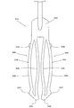
- the holding member 131 is formed to extend from the base portion 132 in a direction opposite to the direction in which the handle 121 extends. That is, the holding member 131 has a base portion 132 and a distal end portion 133, and an intermediate portion 134 that extends from the base portion 132 toward the distal end portion 133 is formed.
- the front end portions 133 of the two holding members 131 are free ends.
- the intermediate part 134 includes a first elastic member 135 and a second elastic member 136. That is, the first elastic member 135 and the second elastic member 136 are connected to each other on the base 132 side and the distal end 133 side. And in the area
- the first elastic member 135 protrudes below the cleaning body holder 110 (downward in FIG. 3) from the base portion 132 and the distal end portion 133 in the region between the base portion 132 and the distal end portion 133.
- the second elastic member 136 protrudes above the cleaning body holder 110 (upward in FIG. 3) from the base portion 132 and the tip portion 133 in the region.
- the first elastic member 135 of one holding member 131 and the first elastic member 135 of the other holding member 131 are close to each other in the region between the base portion 132 and the distal end portion 133.
- the second elastic member 136 of one holding member 131 and the second elastic member 136 of the other holding member 131 are arranged so as to be separated from each other in the region.
- the intermediate portion 134 configured as described above is configured so that the first elastic member 135 and the second elastic member 136 constituting one holding member 131 are in the region of the intermediate portion between the base portion 132 and the distal end portion 133. Are arranged so as to be most separated in the vertical direction and the horizontal direction. These separation distances are indicated by the left-right direction separation distance W of the cleaning body holder 110 in FIG. 2 and the up-down direction separation distance D of the cleaning holder 110 in FIG. Since the first elastic member 135 and the second elastic member 136 are molded of a resin material, the first elastic member 135 and the second elastic member 136 are configured to bend in the vertical direction and the horizontal direction of the cleaning body holder 110 by elastic deformation.
- the vertical separation distance D in the vertical direction of the cleaning body holder 110 is the vertical direction by elastically deforming the first elastic member 135 and the second elastic member 136. It is preferable that the ratio of the first elastic member 135 and the second elastic member 136 to the distance between the first elastic member 135 and the second elastic member 136 is 250% or more.
- convex portions 137 and 138 are formed on the side surfaces of the second elastic member 136. That is, a convex portion 137 is formed on the distal end 133 side of the second elastic member 136, and a convex portion 138 is formed on the base 132 side of the second elastic member 136. These convex portions 137 and 138 are formed in a semicircular shape in plan view.
- the holding plate 139 is formed so as to protrude from the base portion 132.
- the holding plate 139 is formed between the pair of holding members 131 so as to extend in parallel with the holding member 131.
- the presser plate 139 is configured as a plate-like member that is curved so as to be convex downward, and further includes a locking projection (not shown) on the lower surface.
- the cleaning body 140 is a sheet-like cleaning body having a dirt scraping function for scraping off dirt on a surface to be cleaned which is a cleaning target in wiping cleaning. As shown in FIGS. 5 and 6, the cleaning body 140 is formed in a rectangular shape in plan view. The long side direction of the cleaning body 140 substantially matches the direction in which the extending directions in which the plurality of fibers constituting the fiber assembly extend intersect.
- the cleaning body 140 is mainly composed of a cleaning body main body 150 and a holding sheet 160.
- This cleaning body 140 is a disposable type that is used once as a guide, or a disposable type that is exchanged using multiple times as a guide while holding dust and dust removed from the surface to be cleaned. It may be of a type that can be used repeatedly after washing or the like.
- the cleaning body body 150 is formed by laminating and joining a sheet-like base material sheet 151, a fiber assembly 152, and a cleaning target side sheet 153.
- the base sheet 151, the fiber assembly 152, and the cleaning target side sheet 153 have the same rectangular shape in plan view, and all extend in a long shape in the long side direction of the cleaning body 140.
- the fiber assembly 152 and the cleaning target side sheet 153 constitute a brush-like portion having a dirt scraping function, and are also referred to as a so-called “brush portion”.
- This fiber assembly 152 is an implementation configuration example corresponding to the “fiber assembly” in the present invention.
- the base sheet 151 and the cleaning target side sheet 153 are sheets formed of a rectangular nonwoven fabric.
- the cleaning target side sheet 153 includes a plurality of zigzag strips 153 a extending in parallel in the short side direction of the cleaning body 140.
- the fiber assembly 152 includes a single fiber structure made of fibers, or a fiber structure in which fibers are aligned in the length direction and / or radial direction (twisted yarn, spun yarn, and a plurality of long fibers. Partly connected thread material or the like) or an aggregate of the fiber structure, and is configured as a fiber aggregate that includes thermoplastic fibers in part and can be fused (also referred to as “welding”). .
- the fiber forming the fiber assembly 152 is a structural unit such as a thread or a woven fabric, and has a thin and flexible shape having a sufficient length compared to the thickness. Typically, long continuous fibers are long fibers (filaments), and short fibers are short fibers (staples).
- the fibers of the fiber assembly 152 are joined at the proximal end side by the central weld line 170 and the welded joints 171, 172, and 173, and the side opposite to the fixed end (front end side) with the welded joint part as a fixed end ) As a free end, and the cleaning body 140 (or the fiber assembly 152) extends in the long side direction.
- the fiber assembly 152 is also referred to as a “fiber bundle” in which a plurality of fibers are formed in a bundle shape.
- the weld joints 171, 172, 173 form a holding space 180 as will be described later.
- These welded joints 171, 172, and 173 are an implementation configuration example corresponding to the “first joint” in the present invention.
- the fiber assembly 152 is formed by laminating three fiber layers, the number of fiber layers can be one or more as necessary.
- the fiber assembly 152 preferably has a planar structure with a predetermined plane or curved surface, and is configured as a three-dimensional shape having a certain thickness or a thin sheet shape.
- the fiber assembly 152 is typically made of polyethylene (PE), polypropylene (PP), polyethylene terephthalate (PET), nylon, rayon, etc., and is practically a long fiber (filament) obtained by opening the tow. ) Is preferably used.
- the core portion is made of polypropylene (PP) or polyethylene terephthalate (PET), and the sheath portion covering the outer surface of the core portion is made of a composite fiber of polyethylene (PE).
- the fineness of the long fibers forming the fiber assembly 152 is preferably 1 to 50 dtex, more preferably 2 to 10 dtex.
- each fiber assembly may be composed of fibers having substantially the same fineness, or each fiber assembly may include fibers having different finenesses.
- a fiber assembly including fibers having high rigidity that is, fibers having high fineness.
- the fiber assembly is preferably configured to have crimped fibers.
- a crimped fiber here is comprised as a fiber to which the predetermined winding shrinkage process was provided, and is set as the structure where fibers are easy to get entangled. When such a crimped fiber is used, the fiber assembly becomes bulkier than the state before the cleaning body holder is mounted, and further, a structure in which dust is easily taken into the crimped portion is obtained. This structure can be realized in particular by using crimped fibers formed from tow fibers.
- the holding sheet 160 is a sheet formed of a rectangular nonwoven fabric whose long side direction is shorter than the base sheet 151 in the long side direction of the cleaning body 140.
- non-woven fabric sheet 151 As the non-woven fabric constituting the base sheet 151, the cleaning target side sheet 153, and the holding sheet 160 , a sheet-like non-woven fabric made of heat-meltable fibers (thermoplastic fibers) is typically used. That is, the base sheet 151, the cleaning target side sheet 153, and the holding sheet 160 are also referred to as “nonwoven fabric sheet” or “sheet member”. This sheet member is an example of the “sheet member” according to the present invention. In addition, in order to improve the sweeping-out function at the time of cleaning, it is preferable to use a highly rigid nonwoven fabric.
- the cleaning body main body 150 and the holding sheet 160 are positioned on both sides of the central welding line 170 that extends the central portion of the cleaning body 140 in the long side direction of the cleaning body 140 and the central welding line 170.
- a plurality of circular welded joints 171, 172, and 173 are welded and joined. That is, as shown in FIG. 7, the base sheet 151, the fiber assembly 152, and the cleaning target side sheet 153 constituting the cleaning body main body 150 and the holding sheet 160 are welded and joined at the center welding wire 170. Yes. Further, the base material sheet 151 and a part of the fiber assembly 152 in the cleaning body main body 150 and the holding sheet 160 are welded and joined at the welded joints 171, 172, and 173.
- a pair of holding spaces 180 extending in the long side direction of the cleaning body 140 are formed between the central welding wire 170 and the welding joints 171, 172, and 173 by welding the sheets as described above. Has been.
- openings 181 are formed at both ends of the cleaning body 140 in the long side direction in the holding space 180.
- This holding space 180 is an implementation configuration example corresponding to the “insertion portion” in the present invention.
- the holding space 180 is formed by a predetermined region of the holding sheet 160 and a predetermined region of the base sheet 151 between the pair of welded joints 171, 172, and 173.
- a predetermined area of the holding sheet 160 located above the cleaning tool 100 (upper side in FIG. 3) in the holding space 180 is defined as a first area 180A.
- a predetermined region of the base sheet 151 located on the lower side of the cleaning tool 100 (lower side in FIG. 3) in the holding space 180 is defined as a second region 180B.
- the first area 180A and the second area 180B are implementation configuration examples corresponding to the “first area” and the “second area” in the present invention.
- the plurality of welded joints 171, 172, and 173 are arranged to form a curved line in the long side direction of the cleaning body 140. That is, the welding joint 171 on the opening 181 side is disposed in the vicinity of the central welding line 170 in the short side direction of the cleaning body 140.
- the weld joint 172 is disposed in an intermediate region 182 between the openings 181 at both ends in the long side direction of the cleaning body 140, and is disposed farther from the central weld line 170 than the weld joint 171. .
- the weld joint 173 is disposed further away from the central weld line 170.
- the holding space 180 has a configuration in which the cross-sectional area of the intermediate region 182 is larger than the cross-sectional area of the opening 181 in the short side direction of the cleaning body 140.
- the holding space 180 is configured such that the displacement amount of the intermediate region 182 is larger than the opening 181 in the thickness direction of the cleaning body 140.
- each holding member 131 can be inserted into the holding space 180.
- the cleaning body 140 is held by the cleaning body holder 110.
- the width of the opening 181 of the holding space 180 is formed to be smaller than the larger one of the left-right direction separation distance W and the up-down direction separation distance D of the first holding member 135 and the second holding member 136. Therefore, in the process of inserting the holding member 131 into the holding space 180, the first elastic member 135 and the second holding member 136 are elastically deformed so as to be close to each other when passing through the opening 181.
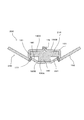
- the first elastic member 135 and the second elastic member 136 After the first elastic member 135 and the second elastic member 136 pass through the opening 181, the first elastic member 135 and the second elastic member 136 are separated from each other in the intermediate region between the base portion 132 and the distal end portion 133 due to the restoring force. Deform in the direction. That is, it is deformed to return to the initial state. Accordingly, as shown in FIG. 9, the holding space 180 is expanded in the vertical direction by the first elastic member 135 and the second elastic member 136.
- the convex portions 137 and 138 are held between the welded joint portions 172.
- the first elastic member 135 pushes the holding sheet 160 upward by the restoring force of the first elastic member 135 and the second elastic member 136, and the second elastic member 136 is a base sheet. Press 151 down.
- the holding member 131 is engaged with the intermediate region 182 in the holding space 180.
- the presser plate 139 presses the cleaning body 140 from above, and a locking projection (not shown) provided on the lower surface of the presser plate 139 acts as a retaining member for the cleaning body 140.
- the holding member 130 may be inserted into the holding space 180 from any opening 181 formed at both ends of the cleaning body 140.
- the cleaning body holding unit 130 expands and holds the cleaning body 140 in the vertical direction. That is, the holding member 131 is formed of a first elastic member 135 and a second elastic member 136 that can be elastically deformed, and the cleaning body 140 is moved in the thickness direction by the restoring force of the first elastic member 135 and the second elastic member 136. Has been extended to. Therefore, as shown in FIG. 9, the cleaning body 140 is held in a state where the bulk is increased (a state indicated by a dotted line).
- the bulk of the fiber assembly 152 is increased.
- the state in which the bulk of the fiber assembly 152 is increased can be defined as a state with a high volume feeling, and can be defined as a “bulky state”, “volume up state”, “space fullness state” or “high bulky degree”. It can also be called “state”. Therefore, it is possible to improve the cleaning effect by increasing the bulk of the fiber assembly 152.
- the degree of adhesion to the surface to be cleaned is increased, the stain of the fiber assembly 152 is easily noticeable (is likely to become black), and the user is surely trapped with dust. The satisfaction will be increased.
- the first elastic member 135 and the second elastic member 136 are not only separated in the vertical direction of the cleaning body holder 110 but also separated in the left-right direction of the cleaning body holder 110. Yes. That is, the first elastic member 135 and the second elastic member 136 are spaced apart from each other in the thickness direction of the cleaning body 140, and not only hold the cleaning body 140 bulky but also intersect the thickness direction of the cleaning body 140.
- the cleaning body 140 is secured in the plan view so as to be spaced apart from each other. In other words, the cleaning body 140 is held bulky while suppressing the area in plan view from becoming smaller. Therefore, the cleaning body 140 can be held bulky in a wide range, and the cleaning efficiency can be improved.
- the holding member 131 presses in the direction of expanding the inside of the holding space 180. That is, the first elastic member 135 of the holding member 131 presses the second region 180 ⁇ / b> B of the holding space 180. Further, the second elastic member 136 of the holding member 131 presses the first region 180 ⁇ / b> A of the holding space 180. As a result, tension is applied to the first region 180A and the second region 180B in the holding space 180. That is, the first elastic member 135 and the second elastic member 136 in the holding member 131 serve as a tension applying unit 190 that applies a predetermined tension to the second region 180B in the holding space 180.
- the second elastic member 136 is a first tension applying portion 190A.
- the first elastic member 135 is a second tension applying member 190B.
- the structure of the holding member 131 is an implementation configuration example corresponding to the “tension applying portion” in the present invention.
- the first tension applying unit 190A and the second tension applying unit 190B are implementation configuration examples corresponding to the “first tension applying unit” and the “second tension applying unit” in the present invention.
- the first elastic member 135 is disposed on the inner side in the longitudinal cross direction X than the second elastic member 136. That is, the second tension applying unit 190B is arranged on the inner side in the longitudinal cross direction X than the first tension applying unit 190A.
- the second region 180B is the second region 180B. The tension is applied from the bottom to the top (from bottom to top in FIG. 3) while being tensioned from the tension applying portion 190B (first elastic member 135) to the first tension applying portion 190A (second elastic member 136). That is, the second region 180B forms a tension portion 191.
- This tension portion 191 is an implementation configuration example corresponding to the “tension portion” in the present invention.
- the second region 180B is inclined in the direction in which the first region 180A is arranged (upward in FIG. 3). Further, the sheet members (base sheet 151 and holding sheet 160) that are continuous with the second region 180B are also moved in the direction in which the first region 180A is arranged (upward in FIG. 3). This is the “in the state where the holding portion of the holder is inserted into the insertion portion of the cleaning sheet, in the present invention, the tension is applied to the second region of the cleaning sheet by the tension applying portion of the holding portion. And the sheet member in the longitudinal crossing direction in the tension portion is moved in the direction in which the first region is disposed.
- the cleaning body 140 As a result, in the cleaning body 140, the distance between the sheet member (base sheet 151, holding sheet 160) and the cleaning target side sheet 153 is separated. That is, the area where the cleaning body 140 should come into contact with the object to be cleaned can be increased. Furthermore, in the cleaning tool 100 having this type of fiber assembly 152, the user may open the fiber assembly 152 by shaking the cleaning tool 100 before use. In the present invention, a region where the fiber assembly 152 is to be opened can be secured. Therefore, the opened state of the fiber assembly 152 is favorable.
- the cleaning body holding part 130 is formed with two holding members 131 in a bifurcated shape, the area in the plan view of the cleaning body 140 is large when the cleaning body holder 110 holds the cleaning body 140 bulky. It can further be suppressed from becoming smaller.
- the first elastic member 135 and the second elastic member 136 are the most in the vertical direction and the horizontal direction of the cleaning body holder 110 at the intermediate portion located at an equal distance from the base portion 132 and the distal end portion 133. It is separated. Therefore, the cleaning body 140 can be most bulky at the center of the cleaning body 140 held by the cleaning body holder 110. Thereby, the cleaning body 140 can be efficiently held bulky.
- the holding member 131 is held in the holding space 180 by the restoring force of the first elastic member 135 and the second elastic member 136 in a state where the cleaning body 140 is held by the cleaning body holder 110.
- seat 153 since the cleaning object side sheet
- the weld joints 171, 172, and 173 are not only arranged symmetrically with respect to the central weld line 170, but also pass through the center of the central weld line 170 and are perpendicular to the central weld line 170. It is preferable that they are arranged symmetrically with respect to the straight line. According to such a configuration, the holding member 131 can be inserted into the holding space 180 from any opening 181.
- the cleaning tool 140 of the cleaning tool according to the first modification is provided with a high-rigidity region 174 in a sheet member (base material sheet 151, holding sheet 160).
- region 174 is not provided is set as a low rigidity area
- the high-rigidity region 174 and the low-rigidity region are implementation examples of the “high-rigidity region” and the “low-rigidity region” of the present invention.
- the sheet member (base sheet 151, holding sheet 160) provided with the high-rigidity region 174 may be the holding sheet 160 or the base sheet 151. It is also possible to provide both the base sheet 151 and the holding sheet 160.
- the high rigidity region 174 extends continuously in the longitudinal cross direction X. Accordingly, the movement of the sheet member (base sheet 151, holding sheet 160) in the direction in which the first region 180A is arranged (upward in FIG. 3) becomes more reliable.
- the welding joints 171, 172, 173 (first joints) and the high-rigidity region 174 can be provided continuously. Accordingly, the movement of the sheet member (base sheet 151, holding sheet 160) in the direction in which the first region 180A is arranged (upward in FIG. 3) becomes more reliable.
- the high-rigidity region 174 is configured by applying an adhesive such as a hot-melt adhesive to predetermined regions of the sheet member (base material sheet 151 and holding sheet 160).
- the high-rigidity region 174 is configured by sticking a non-woven fabric formed in a predetermined size to a predetermined region of the sheet member (base sheet 151, holding sheet 160).
- the high-rigidity region 174 is configured by a second joint portion in which predetermined regions of the sheet member (base material sheet 151 and holding sheet 160) are welded.
- the second joint portion that is the high-rigidity region 174 is an implementation configuration example of the “second joint portion” of the present invention.
- the cleaning tool according to the third modification the high-rigidity region 174 of the sheet member (base sheet 151, holding sheet 160) is formed by the second joint portion 175.
- a part of the fiber assembly 152 can be welded to the second joint portion 175. Therefore, a part of the fiber assembly 152 is connected to the strip pieces 151a and 160a where the second welded portion 175 exists. Therefore, when a cleaning operation is performed using the sheet members (base sheet 151, holding sheet 160), the possibility that dust or the like can be captured by the fiber assembly 152 is improved.
- the cleaning tool 200 of FIG. 13 includes a cleaning body holder 210 and a cleaning body 240.
- the cleaning body holder 210 has a holding member 131.
- the holding member 131 has a single long structure extending in the longitudinal direction Y.
- the holding member 131 constitutes a tension applying unit 190. That is, one side (upper side in FIG. 13) in the thickness direction of the holding member 231 is the first tension applying portion 190A. Further, the holding member 231 has a convex portion on the other side (downward in FIG. 13) in the thickness direction. This convex portion is the second tension applying portion 190B.
- the holding space 180 in the cleaning body 240 of the cleaning tool 200 is formed by joining both end portions of the holding space sheet 161, which is a single sheet-like member, at the welding joint portion 176. Even with such a configuration, the first region 180A and the second region 180B of the holding space 180 according to the present invention can be configured. Note that a brush sheet 162 forming a brush portion is joined to the holding space sheet 161.
- the holding member 131 presses in the direction of expanding the inside of the holding space 180. That is, the first tension applying unit 190A of the holding member 131 presses the first region 180A of the holding space 180. Further, the second tension applying portion 190 ⁇ / b> B of the holding member 131 presses the second region 180 ⁇ / b> B of the holding space 180. As a result, tension is applied to the first region 180A and the second region 180B in the holding space 180.
- the second tension applying unit 190B is disposed on the inner side in the longitudinal crossing direction X than the first tension applying unit 190A. Therefore, the second region 180B is inclined while being tensioned from the bottom to the top (from bottom to top in FIG. 13) from the second tension applying portion 190B to the first tension applying portion 190A (second elastic member 136). Is done. That is, the second region 180B forms a tension portion 191.
- the second region 180B is inclined in the direction in which the first region 180A is disposed (upward in FIG. 13). Further, the brush sheet 160 continuous with the second region 180B is also moved in the direction in which the first region 180A is arranged (upward in FIG. 13).
- the second elastic member 136 has a convex portion 237 and a convex portion 238.
- the convex portion 237 is provided on the distal end portion 133 side of the second elastic member 136.
- the convex portion 238 is provided on the base 132 side of the second elastic member 136.
- the insertion direction Y1 is a direction in which the holding member 131 of the cleaning body holder 110 is inserted into the holding space 180 of the cleaning body 140.
- This insertion direction Y1 is the implementation structural example corresponding to the "insertion direction” in this invention.
- the drawing direction Y2 is a direction in which the holding member 131 of the cleaning body holder 110 inserted into the holding space 180 of the cleaning body 140 is pulled out.
- This drawing direction Y2 is a direction facing the opposite direction to the insertion direction Y1.
- This drawing direction Y2 is an implementation configuration example corresponding to the “drawing direction” in the present invention.
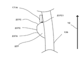
- the convex portion 237 has an insertion side region 237A provided on the insertion direction Y1 side and a drawing side region 237C provided on the drawing direction Y2 side. Furthermore, the convex part 237 has an intermediate region 237B provided between the insertion side region 237A and the extraction side region 237C.
- the insertion side region 237A, the intermediate region 237B, and the extraction side region 237C are implementation configuration examples corresponding to the “insertion side region”, “intermediate region”, and “extraction side region” in the present invention.
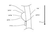
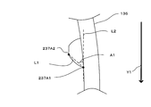
- FIG. 15 shows a state in which the cleaning body holder 110 is moved in the insertion direction Y ⁇ b> 1 and the holding member 131 of the cleaning body holder 110 is inserted into the holding space 180 of the cleaning body 140.
- the insertion side region 237A of the convex portion 237 comes into contact with the joint portion 171A of the cleaning body 140.
- a point where the insertion side region 237A first comes into contact with the joint 171A is defined as an insertion start point 237A1.
- This insertion start point 237A1 is an implementation configuration example corresponding to the “insertion start point” in the present invention.
- the cleaning body holder 110 is further moved in the insertion direction Y1 until the insertion side region 237A finally comes into contact with the joint portion 171A.
- the point where the insertion side region 237A finally comes into contact with the joint portion 171A is defined as an insertion end point 237A2.
- This insertion end point 237A2 is an implementation configuration example corresponding to the “insertion end point” in the present invention.
- the cleaning body holder 110 is further moved in the insertion direction Y1. Then, the joint portion 171A passes through the insertion end point 237A2 and comes into contact with the intermediate region 237B. Further, by moving the cleaning body holder 110 in the insertion direction Y1, the mounting of the cleaning body holder 110 and the cleaning body 140 is completed.
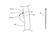
- a straight line connecting the insertion start point 237A1 and the insertion end point 237A2 is defined as a first virtual straight line L1.
- a straight line parallel to the insertion direction Y1 passing through the insertion start point 237A1 is defined as a second virtual straight line L2.
- the angle formed by the first virtual line L1 and the second virtual line L2 is defined as a first angle A1.
- the first virtual straight line L1, the second virtual straight line L2, and the first angle A1 correspond to the “first virtual straight line”, “second virtual straight line”, and “first angle” in the present invention. It is an implementation structural example.
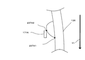
- FIG. 19 shows a state in which the cleaning body holder 110 is moved in the drawing direction Y2 from the state where the cleaning body holder 110 and the cleaning body 140 are mounted.
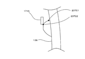
- the pull-out side region 237C of the convex portion 237 comes into contact with the joint portion 171A of the cleaning body 140.
- a point where the drawing side region 237C first comes into contact with the joint portion 171A is a drawing start point 237C1.
- This drawing start point 237C1 is an implementation configuration example corresponding to the “drawing start point” in the present invention.
- the cleaning body holder 110 is further moved in the drawing direction Y2 until the drawing side region 237C finally comes into contact with the joint portion 171A.
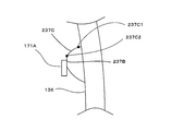
- the point where the drawing side region 237C finally comes into contact with the joint portion 171A is defined as a drawing end point 237C2.
- This drawing end point 237C2 is an implementation configuration example corresponding to the “drawing end point” in the present invention.
- the cleaning body holder 110 is further moved in the drawing direction Y2. Then, the joint portion 171A passes through the drawing end point 237C2 and comes into contact with the intermediate region 237B. And the cleaning body holder 110 is removed from the cleaning body 140 by moving the cleaning body holder 110 further in the drawing direction Y2.
- a straight line connecting the drawing start point 237C1 and the drawing end point 237C2 is defined as a third virtual straight line L3.
- a straight line parallel to the drawing direction Y2 passing through the drawing start point 237C1 is defined as a fourth virtual straight line L4.
- the angle formed by the third virtual straight line L3 and the fourth virtual straight line L4 is defined as a second angle A2.
- the third virtual straight line L3, the fourth virtual straight line L4, and the second angle A2 correspond to “third virtual straight line”, “fourth virtual straight line”, and “second angle” in the present invention. It is an implementation structural example.
- the first angle A1 is configured to be smaller than the second angle A2.
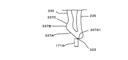
- the cleaning body holder 330 of the cleaning body holder 310 according to the fifth modification is configured by a first elastic member 335 and a second elastic member 336.
- the second elastic member 336 includes a convex portion 337 on the distal end portion 333 side and a convex portion 338 on the base portion 332 side.
- the convex portion 337 on the distal end portion 333 side is formed by deforming the distal end portion 333 side of the second elastic member 336 outward.
- the convex portion 337 on the distal end portion 333 side of the cleaning body holder 310 according to the fifth modified example has a second elasticity compared to the convex portion 237 on the distal end portion 133 side of the cleaning body holder 110 according to the fourth modified example.
- the boundary between the member 336 and the convex portion 337 is not clear. Further, with regard to the convex portion 337 having such a structure, there is a problem in particular where the insertion side region 337A of the convex portion 337 starts.
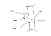
- FIG. 25 shows a state in which the cleaning body holder 310 is moved in the insertion direction Y ⁇ b> 1 and the holding member 331 of the cleaning body holder 310 is inserted into the holding space 180 of the cleaning body 340.
- the convex portion 337 comes into contact with the joint portion 171A of the cleaning body 340.
- a point where the insertion side region 237A first comes into contact with the joint portion 171A is defined as an insertion start point 337A1.
- a portion extending from the insertion start point 337A1 to the intermediate portion 337B is defined as an insertion side region 337A of the convex portion 337.
- FIG. 27 shows a state in which the cleaning body holder is moved in the insertion direction Y1, the holding member of the cleaning body holder is inserted into the holding space 180 of the cleaning body 140, and the cleaning body holder is moved in the pulling direction Y2.
- FIG. 27 shows both the state which pulls out the holding member of a holder from the holding space 180 of the cleaning body 140.
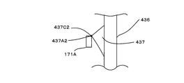
- FIG. In the case of the convex portion 437 having such a structure, the insertion end point 437A2 and the drawing end point 437C2 coincide with each other in the intermediate region 437B. On the other hand, even if the insertion end point 437A2 and the drawing end point 437C2 are the same portion in the convex portion 437, there is no problem in obtaining the “first angle” and the “second angle”.
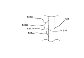
- the convex portion 537 has a concave portion 537AA in the insertion side region 537A.
- FIG. 29 is an explanatory diagram illustrating a state in which the cleaning body holder is moved in the insertion direction Y ⁇ b> 1 and the holding member of the cleaning body holder is inserted into the holding space 180 of the cleaning body 140.
- the contact state between the insertion region 537A and the joint portion 171A is different from the convex portions according to the third to fifth modifications described above. That is, the joining portion 171A passes through the recess 537AA from the insertion start point (not shown) of the insertion region 537A of the projection 537 to the insertion end point 537A1.
- the insertion end point 537A2 is only the point where the insertion side region 537A comes into contact with the joint portion 171A last. This is the same even when the extraction side region 537C has a recess. Therefore, even if the convex portion 537 has the concave portion 537AA, there is no problem in obtaining the “first angle” and the “second angle”.
- each joint portion continuous in the longitudinal direction is The first angle A1 and the second angle A2 may be different angles.
- 1st angle A1 let the smallest angle be a "1st angle” which concerns on this invention.
- 2nd angle A2 let the largest angle be a "2nd angle” which concerns on this invention.
- the cleaning body holder 110 has the two holding members 131 in a bifurcated shape, but may have only one holding member 131 without being formed in a bifurcated shape.
- the cleaning tools 100 and 200 are examples of the “cleaning tool” according to the present invention.
- the cleaning bodies 140 and 240 are examples of the “cleaning sheet” according to the present invention.
- the cleaning body holders 110, 210, and 310 are examples of the “holding tool” according to the present invention.
- the longitudinal direction Y is an example of the “longitudinal direction” according to the present invention.
- the longitudinal cross direction X is an example of the “longitudinal cross direction” according to the present invention.
- the first region 180A is an example of the “first region” according to the present invention.
- the second area 180B is an example of the “second area” according to the present invention.
- the holding space 180 is an example of the “insertion portion” according to the present invention.
- the base sheet 151, the holding sheet 160, and the brush sheet 162 are examples of the “sheet member” according to the present invention.
- the cleaning body holding units 130 and 330 are examples of the “holding unit” according to the present invention.
- the tension application 190 is an example of the “tension application unit” according to the present invention.
- the first tension applying unit 190A is an example of the “first tension applying unit” according to the present invention.
- the second tension applying unit 190B is an example of the “second tension applying unit” according to the present invention.
- the high rigidity region 174 is an example of the “high rigidity region” according to the present invention.
- the welded joints 171, 172, 173, 271, 273, 371, and 171 ⁇ / b> A are examples of the “first joint” according to the present invention.
- the 2nd junction part 175 is an example of the "2nd junction part” concerning the present invention.
- the insertion direction Y1 is an example of the “insertion direction” according to the present invention.
- the drawing direction Y2 is an example of the “drawing direction” according to the present invention.
- the convex portions 137, 138, 237, 238, 337, 338, 437, 537 are examples of the “convex portion” according to the present invention.
- the insertion side regions 237A, 337A, 437A, and 537A are examples of the “insertion side region” according to the present invention.
- the drawing side regions 237C, 337C, 437C, and 537C are examples of the “drawing side region” according to the present invention.
- the intermediate regions 237B, 337B, 437B, and 537B are examples of the “intermediate region” according to the present invention.
- the insertion start points 237A1 and 337A1 are examples of the “insertion start point” according to the present invention.
- the insertion end points 237A2, 437A2, and 537A2 are examples of the “insertion end point” according to the present invention.
- the first virtual straight line L1 is an example of the “first virtual straight line” according to the present invention.
- the second virtual straight line L2 is an example of the “second virtual straight line” according to the present invention.
- the first angle A1 is an example of the “first angle” according to the present invention.
- the drawing start point 237C1 is an example of the “drawing start point” according to the present invention.
- the drawing end points 237C2, 437C2, and 537C2 are examples of the “drawing end points” according to the present invention.
- the third virtual straight line L3 is an example of the “third virtual straight line” according to the present invention.
- the fourth virtual straight line L4 is an example of the “fourth virtual straight line” according to the present invention.
- the second angle A2 is an example of the “second angle” according to the present invention.
- the holding member 131 is an example of a “long member” according to the present invention.
- the base 132 is an example of the “joining part” according to the present invention.
- the first elastic members 135, 235 and the second elastic members 136, 236, 336, 436 are examples of “two elastic members” according to the present invention.
- the cleaning tool according to the present invention can be configured as follows.
- (Aspect 1) A cleaning sheet;
- a cleaning tool comprising a holder for holding the cleaning sheet,
- the cleaning tool has a longitudinal direction that is a direction of inserting the holding tool into the cleaning sheet, and a longitudinal crossing direction that is a direction intersecting the longitudinal direction,
- the cleaning sheet is A first region composed of a sheet member, a second region composed of a sheet member, and an insertion space continuous in the longitudinal direction are formed between the first region and the second region so that the holder can be inserted.
- the holding tool is inserted into the insertion space of the cleaning sheet and holds the cleaning sheet, and a tension applying unit that is provided in the holding unit and applies a predetermined tension to the second region of the cleaning sheet.
- a gripping part connected to the holding part and gripped by a user, In a state where the holding portion of the holder is inserted into the insertion portion of the cleaning sheet, the tension applying portion of the holding portion applies tension to the second region of the cleaning sheet to form a tension portion, and The cleaning tool, wherein the sheet member in the longitudinal crossing direction in the tension portion is moved in a direction in which the first region is arranged.
- the tension applying unit includes a first tension applying unit that applies tension to the first region of the cleaning sheet, and a second tension applying unit that applies tension to the second region of the cleaning sheet.
- a cleaning tool In the cleaning tool described in any one of aspects 1 or 2, The cleaning tool according to claim 1, wherein the second tension applying unit is disposed on an inner side in the longitudinal crossing direction than the first tension applying unit.
- the said tension part is formed ranging from a said 2nd tension provision part to a said 1st tension provision part, The cleaning tool characterized by the above-mentioned.
- a cleaning tool In the cleaning tool described in any one of aspects 1 to 4, A cleaning tool, wherein the sheet member includes a high-rigidity region having high rigidity and a low-rigidity region having lower rigidity than the high-rigidity region.
- the high-rigidity region continuously extends in the longitudinal cross direction.
- a cleaning tool comprising a first joint for connecting the first region and the second region, wherein the first joint and the high-rigidity portion are continuous.
- a cleaning tool according to any one of aspects 5 to 7, The high-rigidity portion is a second joint portion where the sheet member is welded.
- the cleaning sheet has a fiber assembly, The second bonding portion connects a part of the fiber assembly and a strip piece.
- the convex portion includes an insertion start point which is a point where the insertion side region first comes into contact with the joint portion in a state where the holder is inserted into the insertion portion, and a state where the holder is inserted into the insertion portion.
- An insertion end point that is the last point where the insertion-side region contacts the joint, a first imaginary straight line formed by connecting the insertion start point and the insertion end point, and the insertion start point
- a second imaginary straight line that is a straight line parallel to the insertion direction passing through, a first angle formed by the first imaginary straight line and the second imaginary straight line, and the holder from the insertion portion.
- the drawing start point which is the point at which the drawing side region first comes into contact with the joint in the pulled out state, and the drawing side region finally comes into contact with the joint in the state where the holder is pulled out from the insertion part.
- the drawing end point which is a point, and the drawing A third imaginary straight line formed by connecting a start point and the drawing end point, a fourth imaginary straight line passing through the drawing start point and parallel to the drawing direction, and the third imaginary straight line And a second angle formed by the fourth virtual straight line,
Landscapes
- Cleaning Implements For Floors, Carpets, Furniture, Walls, And The Like (AREA)
Abstract
La présente invention vise à fournir un outil de nettoyage, avec lequel une feuille de nettoyage peut être utilisée efficacement pendant le nettoyage. La présente invention concerne un outil de nettoyage (100), comprenant un outil de retenue (110) pour retenir une feuille de nettoyage (140). Dans un état dans lequel des parties de retenue (130) de l'outil de retenue (110) sont introduites dans des parties d'introduction (180) de la feuille de nettoyage (140), des parties de communication de tension (190) des parties de retenue (130) communiquent une force de traction à des secondes régions (180B) de la feuille de nettoyage (140) pour former des parties tension (190), et des éléments de feuille (151) dans les parties tension (191) dans une direction coupant la longueur (X) se déplacent dans des directions dans lesquelles sont disposées des premières régions (180A).
Priority Applications (3)
| Application Number | Priority Date | Filing Date | Title |
|---|---|---|---|
| US14/766,443 US10098517B2 (en) | 2013-02-07 | 2014-01-24 | Cleaning tool |
| CN201480007831.XA CN104981195B (zh) | 2013-02-07 | 2014-01-24 | 清扫工具 |
| EP14749380.3A EP2954826B1 (fr) | 2013-02-07 | 2014-01-24 | Outil de nettoyage |
Applications Claiming Priority (2)
| Application Number | Priority Date | Filing Date | Title |
|---|---|---|---|
| JP2013022747A JP6208948B2 (ja) | 2013-02-07 | 2013-02-07 | 清掃具 |
| JP2013-022747 | 2013-02-07 |
Publications (1)
| Publication Number | Publication Date |
|---|---|
| WO2014123013A1 true WO2014123013A1 (fr) | 2014-08-14 |
Family
ID=51299610
Family Applications (1)
| Application Number | Title | Priority Date | Filing Date |
|---|---|---|---|
| PCT/JP2014/051588 Ceased WO2014123013A1 (fr) | 2013-02-07 | 2014-01-24 | Outil de nettoyage |
Country Status (6)
| Country | Link |
|---|---|
| US (1) | US10098517B2 (fr) |
| EP (1) | EP2954826B1 (fr) |
| JP (1) | JP6208948B2 (fr) |
| CN (1) | CN104981195B (fr) |
| TW (1) | TWI617276B (fr) |
| WO (1) | WO2014123013A1 (fr) |
Families Citing this family (1)
| Publication number | Priority date | Publication date | Assignee | Title |
|---|---|---|---|---|
| JP6506964B2 (ja) * | 2014-12-26 | 2019-04-24 | ユニ・チャーム株式会社 | 清掃シートおよび清掃用具 |
Citations (3)
| Publication number | Priority date | Publication date | Assignee | Title |
|---|---|---|---|---|
| JP2006158866A (ja) * | 2004-12-10 | 2006-06-22 | Oimo Industrial Co Ltd | 回転式はたき |
| JP2011041828A (ja) | 2010-10-28 | 2011-03-03 | Uni Charm Corp | 清掃体及び清掃用具 |
| JP4869984B2 (ja) * | 2007-03-05 | 2012-02-08 | 大日本印刷株式会社 | 清掃用具 |
Family Cites Families (13)
| Publication number | Priority date | Publication date | Assignee | Title |
|---|---|---|---|---|
| US1637595A (en) * | 1924-12-18 | 1927-08-02 | Sturgis Mop Company | Mop |
| CA2384357C (fr) * | 2000-07-10 | 2004-08-10 | Yoshinori Tanaka | Article de nettoyage |
| IL152340A (en) * | 2001-02-23 | 2007-12-03 | Yoshinori Tanaka | Cleaning article |
| CN2726513Y (zh) * | 2004-07-16 | 2005-09-21 | 毛莹 | 清洁刷 |
| JP4662454B2 (ja) * | 2005-04-20 | 2011-03-30 | 花王株式会社 | 清掃具 |
| JP4675218B2 (ja) * | 2005-11-15 | 2011-04-20 | 花王株式会社 | 清掃用物品及びその製造方法 |
| JP4738311B2 (ja) * | 2006-06-01 | 2011-08-03 | 花王株式会社 | 清掃用物品及びその製造方法 |
| JP4731433B2 (ja) | 2006-09-12 | 2011-07-27 | ユニ・チャーム株式会社 | 清掃体及び清掃用具 |
| CN101406377A (zh) * | 2007-10-11 | 2009-04-15 | 杨雅菁 | 清洁布的双向旋紧装置 |
| JP3148559U (ja) * | 2008-12-05 | 2009-02-19 | 憲子 藤巻 | 埃取り掃除具 |
| US8578564B2 (en) | 2009-11-05 | 2013-11-12 | The Procter & Gamble Company | Handle for removable cleaning implement |
| JP5427628B2 (ja) * | 2010-02-03 | 2014-02-26 | ユニ・チャーム株式会社 | 清掃用具、清掃体 |
| JP5685093B2 (ja) * | 2011-01-20 | 2015-03-18 | ユニ・チャーム株式会社 | 清掃用具、清掃用物品 |
-
2013
- 2013-02-07 JP JP2013022747A patent/JP6208948B2/ja active Active
-
2014
- 2014-01-24 EP EP14749380.3A patent/EP2954826B1/fr active Active
- 2014-01-24 CN CN201480007831.XA patent/CN104981195B/zh active Active
- 2014-01-24 US US14/766,443 patent/US10098517B2/en active Active
- 2014-01-24 WO PCT/JP2014/051588 patent/WO2014123013A1/fr not_active Ceased
- 2014-02-07 TW TW103104111A patent/TWI617276B/zh active
Patent Citations (3)
| Publication number | Priority date | Publication date | Assignee | Title |
|---|---|---|---|---|
| JP2006158866A (ja) * | 2004-12-10 | 2006-06-22 | Oimo Industrial Co Ltd | 回転式はたき |
| JP4869984B2 (ja) * | 2007-03-05 | 2012-02-08 | 大日本印刷株式会社 | 清掃用具 |
| JP2011041828A (ja) | 2010-10-28 | 2011-03-03 | Uni Charm Corp | 清掃体及び清掃用具 |
Also Published As
| Publication number | Publication date |
|---|---|
| EP2954826A1 (fr) | 2015-12-16 |
| EP2954826A4 (fr) | 2016-09-07 |
| TWI617276B (zh) | 2018-03-11 |
| JP2014150961A (ja) | 2014-08-25 |
| TW201507683A (zh) | 2015-03-01 |
| CN104981195A (zh) | 2015-10-14 |
| JP6208948B2 (ja) | 2017-10-04 |
| EP2954826B1 (fr) | 2019-09-04 |
| US20150366429A1 (en) | 2015-12-24 |
| US10098517B2 (en) | 2018-10-16 |
| CN104981195B (zh) | 2017-07-28 |
Similar Documents
| Publication | Publication Date | Title |
|---|---|---|
| JP6323980B2 (ja) | 清掃具 | |
| US10694918B2 (en) | Cleaning tool | |
| JP2014168653A5 (fr) | ||
| JP6239827B2 (ja) | 清掃具 | |
| JP6228366B2 (ja) | 清掃具 | |
| JP6133612B2 (ja) | 清掃具 | |
| JP6208948B2 (ja) | 清掃具 | |
| JP6291195B2 (ja) | 清掃具 | |
| JP6126398B2 (ja) | 清掃具 | |
| JP6208949B2 (ja) | 清掃具 | |
| JP6228407B2 (ja) | 清掃用具および清掃用具の製造方法 | |
| JP6239828B2 (ja) | 清掃具 |
Legal Events
| Date | Code | Title | Description |
|---|---|---|---|
| 121 | Ep: the epo has been informed by wipo that ep was designated in this application |
Ref document number: 14749380 Country of ref document: EP Kind code of ref document: A1 |
|
| WWE | Wipo information: entry into national phase |
Ref document number: 14766443 Country of ref document: US |
|
| NENP | Non-entry into the national phase |
Ref country code: DE |
|
| WWE | Wipo information: entry into national phase |
Ref document number: 2014749380 Country of ref document: EP |