WO2014123166A1 - Anneau de tolérance, et dispositif de disque dur - Google Patents
Anneau de tolérance, et dispositif de disque dur Download PDFInfo
- Publication number
- WO2014123166A1 WO2014123166A1 PCT/JP2014/052699 JP2014052699W WO2014123166A1 WO 2014123166 A1 WO2014123166 A1 WO 2014123166A1 JP 2014052699 W JP2014052699 W JP 2014052699W WO 2014123166 A1 WO2014123166 A1 WO 2014123166A1
- Authority
- WO
- WIPO (PCT)
- Prior art keywords
- tolerance ring
- circumferential direction
- hard disk
- base
- carriage
- Prior art date
- Legal status (The legal status is an assumption and is not a legal conclusion. Google has not performed a legal analysis and makes no representation as to the accuracy of the status listed.)
- Ceased
Links
Images


Classifications
-
- G—PHYSICS
- G11—INFORMATION STORAGE
- G11B—INFORMATION STORAGE BASED ON RELATIVE MOVEMENT BETWEEN RECORD CARRIER AND TRANSDUCER
- G11B5/00—Recording by magnetisation or demagnetisation of a record carrier; Reproducing by magnetic means; Record carriers therefor
- G11B5/48—Disposition or mounting of heads or head supports relative to record carriers ; arrangements of heads, e.g. for scanning the record carrier to increase the relative speed
- G11B5/54—Disposition or mounting of heads or head supports relative to record carriers ; arrangements of heads, e.g. for scanning the record carrier to increase the relative speed with provision for moving the head into or out of its operative position or across tracks
- G11B5/55—Track change, selection or acquisition by displacement of the head
- G11B5/5521—Track change, selection or acquisition by displacement of the head across disk tracks
- G11B5/5569—Track change, selection or acquisition by displacement of the head across disk tracks details of specially adapted mobile parts, e.g. electromechanical control devices
-
- F—MECHANICAL ENGINEERING; LIGHTING; HEATING; WEAPONS; BLASTING
- F16—ENGINEERING ELEMENTS AND UNITS; GENERAL MEASURES FOR PRODUCING AND MAINTAINING EFFECTIVE FUNCTIONING OF MACHINES OR INSTALLATIONS; THERMAL INSULATION IN GENERAL
- F16C—SHAFTS; FLEXIBLE SHAFTS; ELEMENTS OR CRANKSHAFT MECHANISMS; ROTARY BODIES OTHER THAN GEARING ELEMENTS; BEARINGS
- F16C19/00—Bearings with rolling contact, for exclusively rotary movement
- F16C19/02—Bearings with rolling contact, for exclusively rotary movement with bearing balls essentially of the same size in one or more circular rows
- F16C19/04—Bearings with rolling contact, for exclusively rotary movement with bearing balls essentially of the same size in one or more circular rows for radial load mainly
- F16C19/08—Bearings with rolling contact, for exclusively rotary movement with bearing balls essentially of the same size in one or more circular rows for radial load mainly with two or more rows of balls
-
- F—MECHANICAL ENGINEERING; LIGHTING; HEATING; WEAPONS; BLASTING
- F16—ENGINEERING ELEMENTS AND UNITS; GENERAL MEASURES FOR PRODUCING AND MAINTAINING EFFECTIVE FUNCTIONING OF MACHINES OR INSTALLATIONS; THERMAL INSULATION IN GENERAL
- F16C—SHAFTS; FLEXIBLE SHAFTS; ELEMENTS OR CRANKSHAFT MECHANISMS; ROTARY BODIES OTHER THAN GEARING ELEMENTS; BEARINGS
- F16C19/00—Bearings with rolling contact, for exclusively rotary movement
- F16C19/52—Bearings with rolling contact, for exclusively rotary movement with devices affected by abnormal or undesired conditions
- F16C19/527—Bearings with rolling contact, for exclusively rotary movement with devices affected by abnormal or undesired conditions related to vibration and noise
-
- F—MECHANICAL ENGINEERING; LIGHTING; HEATING; WEAPONS; BLASTING
- F16—ENGINEERING ELEMENTS AND UNITS; GENERAL MEASURES FOR PRODUCING AND MAINTAINING EFFECTIVE FUNCTIONING OF MACHINES OR INSTALLATIONS; THERMAL INSULATION IN GENERAL
- F16C—SHAFTS; FLEXIBLE SHAFTS; ELEMENTS OR CRANKSHAFT MECHANISMS; ROTARY BODIES OTHER THAN GEARING ELEMENTS; BEARINGS
- F16C27/00—Elastic or yielding bearings or bearing supports, for exclusively rotary movement
- F16C27/04—Ball or roller bearings, e.g. with resilient rolling bodies
-
- G—PHYSICS
- G11—INFORMATION STORAGE
- G11B—INFORMATION STORAGE BASED ON RELATIVE MOVEMENT BETWEEN RECORD CARRIER AND TRANSDUCER
- G11B5/00—Recording by magnetisation or demagnetisation of a record carrier; Reproducing by magnetic means; Record carriers therefor
- G11B5/48—Disposition or mounting of heads or head supports relative to record carriers ; arrangements of heads, e.g. for scanning the record carrier to increase the relative speed
- G11B5/4806—Disposition or mounting of heads or head supports relative to record carriers ; arrangements of heads, e.g. for scanning the record carrier to increase the relative speed specially adapted for disk drive assemblies, e.g. assembly prior to operation, hard or flexible disk drives
- G11B5/4813—Mounting or aligning of arm assemblies, e.g. actuator arm supported by bearings, multiple arm assemblies, arm stacks or multiple heads on single arm
-
- F—MECHANICAL ENGINEERING; LIGHTING; HEATING; WEAPONS; BLASTING
- F16—ENGINEERING ELEMENTS AND UNITS; GENERAL MEASURES FOR PRODUCING AND MAINTAINING EFFECTIVE FUNCTIONING OF MACHINES OR INSTALLATIONS; THERMAL INSULATION IN GENERAL
- F16C—SHAFTS; FLEXIBLE SHAFTS; ELEMENTS OR CRANKSHAFT MECHANISMS; ROTARY BODIES OTHER THAN GEARING ELEMENTS; BEARINGS
- F16C2370/00—Apparatus relating to physics, e.g. instruments
- F16C2370/12—Hard disk drives or the like
-
- F—MECHANICAL ENGINEERING; LIGHTING; HEATING; WEAPONS; BLASTING
- F16—ENGINEERING ELEMENTS AND UNITS; GENERAL MEASURES FOR PRODUCING AND MAINTAINING EFFECTIVE FUNCTIONING OF MACHINES OR INSTALLATIONS; THERMAL INSULATION IN GENERAL
- F16D—COUPLINGS FOR TRANSMITTING ROTATION; CLUTCHES; BRAKES
- F16D1/00—Couplings for rigidly connecting two coaxial shafts or other movable machine elements
- F16D1/06—Couplings for rigidly connecting two coaxial shafts or other movable machine elements for attachment of a member on a shaft or on a shaft-end
- F16D1/08—Couplings for rigidly connecting two coaxial shafts or other movable machine elements for attachment of a member on a shaft or on a shaft-end with clamping hub; with hub and longitudinal key
- F16D1/0829—Couplings for rigidly connecting two coaxial shafts or other movable machine elements for attachment of a member on a shaft or on a shaft-end with clamping hub; with hub and longitudinal key with radial loading of both hub and shaft by an intermediate ring or sleeve
- F16D1/0835—Couplings for rigidly connecting two coaxial shafts or other movable machine elements for attachment of a member on a shaft or on a shaft-end with clamping hub; with hub and longitudinal key with radial loading of both hub and shaft by an intermediate ring or sleeve due to the elasticity of the ring or sleeve
Definitions
- the present invention relates to a hard disk device and a tolerance ring used for the hard disk device and the like.
- hard disk devices are used in devices that perform information processing such as computers.
- this hard disk device has been mounted not only as an external storage device of a computer but also in home appliances such as a television and a video, and in electronic devices for automobiles.
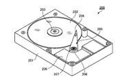
- FIG. 13 is a perspective view showing a schematic configuration of a conventional hard disk device.
- a conventional hard disk device 200 shown in FIG. 13 has a drive mechanism housed in a casing body 201.
- the drive mechanism supports a spindle 203 that rotates and drives a hard disk 202 that is a recording medium (this spindle is rotated by a motor (not shown)), and a magnetic head 204 that records information on and reads information from the hard disk 202.
- a carriage 205 that rotates on the surface of the hard disk 202, a VCM (Voice Coil Motor) 206 that controls the scanning of the magnetic head 204 by precisely rotating the carriage 205, a casing body 201, A pivot shaft 207 that couples the carriage 205 and a tolerance ring 208 that fixes the carriage 205 and the pivot shaft 207 are provided.
- the pivot shaft 207 has a substantially columnar shape, for example, and has a bearing configuration.
- FIG. 14 is a perspective view showing a configuration of a tolerance ring of a conventional hard disk device.
- FIG. 15 is a cross-sectional view showing the structure of the main part of a conventional hard disk device, and shows the structure in the vicinity of the carriage 205, the pivot shaft 207 and the tolerance ring 208.
- the conventional tolerance ring has a convex shape from a substantially rectangular region in the shape of a ring on the outer peripheral surface of a ring-shaped base portion 208a in which a belt-like member is substantially circulated along a predetermined direction.
- a plurality of convex portions 208b (contact portions) projecting from each other are provided.
- a tolerance ring having a plurality of convex contact portions protruding on the outer peripheral side is disclosed (for example, see Patent Documents 1 to 5).
- the contact portion presses against one side surface of the carriage or the pivot shaft to fix the carriage and the pivot shaft.
- the pivot shaft 207 has a bearing as described above to prevent the rotation of the carriage 205 from being transmitted to the casing body 201.
- the pivot shaft 207 includes a rod-shaped member 207a serving as the axis of the pivot shaft 207 and a bearing 207b provided on the outer periphery of the rod-shaped member 207a.
- the bearing 207 b is connected to the carriage 205 via the tolerance ring 208.
- the convex portion 208b of the tolerance ring 208 when the convex portion 208b of the tolerance ring 208 is disposed between the carriage 205 and the pivot shaft 207, the convex portion 208b fixes both the carriage 205 and the pivot shaft 207 in pressure contact with each other.
- the two convex portions 208b are arranged in the circumferential direction at the base portion 208a. It is preferable to be provided respectively on the base end side in the width direction orthogonal to.
- the bearing 207b prevents the central axis from tilting with respect to the central axis of the rod-shaped member 207a, so that the bearing balls forming a row along the outer periphery of the rod-shaped member 207a Are preferably provided at the edge portions of the arrangement area of the carriage 205 along the line.
- the bearing ball and the convex portion 208b of the bearing 207b are provided on the proximal end side of the coupling region of the carriage 205 of the pivot shaft 207 and the proximal end side of the base portion 208a of the tolerance ring 208, respectively.
- the bearing ball and the convex portion 208b are located at substantially the same height when assembled.
- the present invention has been made in view of the above, and provides a tolerance ring and a hard disk device capable of suppressing deterioration of the function of the bearing while maintaining the stability of fixation between the carriage and the pivot shaft.
- the purpose is to do.
- the tolerance ring according to the present invention has a plurality of convex portions protruding in the radial direction from the outer peripheral surface of the base portion in which the band-shaped member substantially circulates to form a ring shape,
- a tolerance ring provided along a circumferential direction of the base portion, wherein the base portion has a substantially cylindrical shape, a cylindrical portion provided with the convex portion, and the circumferential direction and the radial direction in the cylindrical portion;
- One or a plurality of curved portions provided in a part of the orthogonal width direction along the circumferential direction and curved in a convex shape with the main surface of the base portion facing the inner peripheral side of the cylindrical portion.
- the tolerance ring according to the present invention is characterized in that, in the above invention, the curved portions are respectively provided at both ends of the cylindrical portion in the width direction.
- the curved portion is provided between the plurality of convex portions.
- the bending portion is provided continuously along the circumferential direction.
- the tolerance ring according to the present invention is characterized in that, in the above invention, the radius of curvature of the end portion of the base portion in the circumferential direction is smaller than the radius of curvature of the portion other than the end portion in the circumferential direction.
- the tolerance ring according to the present invention is characterized in that, in the above invention, the radius of curvature continuously decreases in a direction from the portion other than the end portion toward the end portion.
- the tolerance ring according to the present invention is characterized in that, in the above invention, the tolerance ring has an edge portion in the width direction of the base portion, and has a notch portion notched in the width direction from at least one edge portion.
- the tolerance ring according to the present invention is characterized in that, in the above invention, one or a plurality of the notches are provided on the one edge.
- the hard disk device supports a hard disk as a recording medium, a magnetic head part for recording and reading information to and from the hard disk, and supports the magnetic head part, and rotates on the surface of the hard disk.
- Provided along the circumferential direction in a part of the circumferential direction and the width direction orthogonal to the radial direction in the cylindrical portion, and the main surface of the base portion is the cylindrical portion One or a plurality of curved portions convexly curved toward the inner peripheral side, and having a
- FIG. 1 is a perspective view showing a schematic configuration of a hard disk device according to an embodiment of the present invention.
- FIG. 2 is a partial cross-sectional view showing a configuration of a main part of the hard disk device shown in FIG.
- FIG. 3 is a perspective view showing a configuration of a main part of the hard disk device shown in FIG.
- FIG. 4 is a perspective view showing a configuration of a tolerance ring used in the hard disk device according to the embodiment of the present invention.
- FIG. 5 is a cross-sectional view showing the configuration of the tolerance ring shown in FIG.
- FIG. 6 is a cross-sectional view showing a configuration of a main part of the hard disk device shown in FIG. FIG.
- FIG. 7 is a perspective view showing a configuration of a tolerance ring according to the first modification of the embodiment of the present invention.
- FIG. 8 is a cross-sectional view showing the configuration of the tolerance ring shown in FIG.
- FIG. 9 is a top view showing the configuration of the tolerance ring according to the second modification of the embodiment of the present invention.
- FIG. 10 is a perspective view showing a configuration of a tolerance ring according to the third modification of the embodiment of the present invention.
- FIG. 11 is a perspective view showing a configuration of a tolerance ring according to the fourth modification of the embodiment of the present invention.
- FIG. 12 is a perspective view showing a configuration of a tolerance ring according to the fifth modification of the embodiment of the present invention.
- FIG. 13 is a perspective view showing a schematic configuration of a conventional hard disk device.
- FIG. 14 is a perspective view showing a configuration of a tolerance ring of a conventional hard disk device.
- FIG. 15 is a cross-sectional view showing a configuration of a main part of a conventional hard disk device.
- FIG. 1 is a perspective view showing a schematic configuration of a hard disk device according to an embodiment of the present invention.
- the hard disk device 1 shown in FIG. 1 has a drive mechanism housed in a casing body 2.
- the drive mechanism supports a spindle 4 that rotationally drives a hard disk 3 that is a recording medium, a magnetic head unit 50 that records information on and reads information from the hard disk 3, and a carriage 5 that rotates on the surface of the hard disk 3;
- a VCM 6 that precisely rotates the carriage 5 to control scanning of the magnetic head unit 50, a columnar pivot shaft 7 that is fixed to the casing body 2 and connects the casing body 2 and the carriage 5, and the carriage 5 and pivot shaft And a tolerance ring 8 for fixing between the two.
- the pivot shaft 7 has a substantially columnar shape, for example, and has a bearing structure in which a bearing ball is disposed, for example.
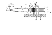
- FIG. 2 is a partial cross-sectional view showing a configuration of a main part of the hard disk device 1 shown in FIG.
- FIG. 3 is a perspective view showing a configuration of a main part of the hard disk device 1 shown in FIG.
- the carriage 5 extends on the surface of the hard disk 3 and is connected to the arm 51 that holds the magnetic head unit 50 at the tip, the pivot shaft 7, and the coupling portion 52 that has a hollow space whose diameter is slightly larger than the diameter of the pivot shaft 7.
- the magnetic head unit 50 includes a suspension 50 a that floats with respect to the surface of the hard disk 3 by an air flow caused by the rotation of the hard disk 3, and an end of the suspension 50 a that is connected to the arm 51.
- a magnetic head 50b that is provided at an end portion on a different side and performs information recording and information reading.
- the carriage 5 has a plurality of magnetic head units 50 according to the number of hard disks 3.
- the VCM 6 includes a coil 60 connected to an end side different from the arm 51 side, and two magnets 61 sandwiching the coil 60.
- the VCM 6 drives the carriage 5 with a force generated by a current flowing through the coil 60 and a magnetic field.
- the carriage 5 rotates on the surface of the hard disk 3 with the central axis of the pivot shaft 7 as a rotation axis by the power from the VCM 6, and rotates the magnetic head unit 50 on the surface of the hard disk 3.
- the pivot shaft 7 has a bearing configuration as described above in order to prevent the rotation of the carriage 5 from being transmitted to the casing body 2.
- the pivot shaft 7 includes a rod-shaped member 71 that serves as an axis of the pivot shaft 7 and a bearing 72 provided on the outer periphery of the rod-shaped member 71.
- the bearing 72 two rows of bearing balls 72 a are arranged along the outer periphery of the rod-shaped member 71 along the central axis direction of the rod-shaped member 71.
- the bearing 72 is connected to the carriage 5 via a tolerance ring 8 described later, and the rod-like member 71 is connected to the casing body 2.
- the bearing ball 72 a rotates according to the rotational power of the carriage 5 by the VCM 6, so that the rotational power of the carriage 5 can be prevented from being transmitted to the rod-like member 71.
- Tolerance ring 8 is used for fixing between carriage 5 and pivot shaft 7.
- the tolerance ring 8 is inserted into the hollow space of the connecting portion 52 of the carriage 5, and the pivot shaft 7 is press-fitted (inserted) therein, thereby fixing between the carriage 5 and the pivot shaft 7.
- the carriage 5 is fixed so as to be rotatable around the central axis of the pivot shaft 7 (rod-like member 71).
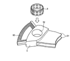
- FIG. 4 is a perspective view showing the configuration of the tolerance ring 8.
- FIG. 5 is a cross-sectional view showing a configuration of the tolerance ring 8, and is a cross-sectional view having a plane parallel to the central axis of the tolerance ring 8 as a cut surface.
- the tolerance ring 8 is provided on the base 80, which is formed by a belt-shaped stainless steel that circulates in a substantially cylindrical shape, and is provided in the radial direction from the base 80 (direction perpendicular to the main surface of the base 80). And a plurality of convex portions 81 projecting from each other.
- the tolerance ring 8 may be formed using other metal materials besides stainless steel.
- the base 80 is provided at the center in the width direction (the direction orthogonal to the circumferential direction and the radial direction of the base 80), and is provided at each of the cylindrical portion 80a having a substantially cylindrical shape and both ends of the cylindrical portion 80a in the width direction. And a curved portion 80b having a principal surface curved.
- the curved portion 80b passes through the inner peripheral surface of the cylindrical portion 80a and is curved toward the substantially cylindrical curved surface N1 extending in the central axis direction of the cylindrical portion 80a. That is, the curved portion 80 b has an arc shape that is convex toward the inner peripheral side of the tolerance ring 8.
- the curved portion 80 b is continuously provided along the circumferential direction of the base portion 80.
- a substantially cylindrical shape that is an edge in the width direction of the curved portion 80b, and an edge on the outer peripheral side passes through the outer peripheral surface of the cylindrical portion 80a and extends in the central axis direction of the cylindrical portion 80a.
- the curved surface N2 On the curved surface N2.
- the convex portion 81 is provided along the circumferential direction of the cylindrical portion 80a and protrudes in the radial direction from the main surface on the outer peripheral side of the cylindrical portion 80a.
- each convex portion 81 is provided in two rows in the width direction of the tolerance ring 8. After the tolerance ring 8 is inserted into the opening on the carriage 5 side, the pivot shaft 7 is press-fitted into the tolerance ring 8. At this time, the convex portion 81 is pressed against the inner wall surface of the connecting portion 52 of the carriage 5, and the carriage 5 and the pivot shaft 7 are fixed.
- the length of the tolerance ring 8 in the circumferential direction is preferably equal to the circumferential length of the opening of the connecting portion 52.
- the plurality of convex portions 81 are described as being provided in two rows in the width direction, but may be one row or three or more rows.
- the number of the convex parts 81 to be arranged is, for example, a number that is a multiple of 3 in the circumferential direction.
- the multiple convex portions 81 By arranging the multiple convex portions 81 in multiples of 3, contact with the contact side surface is symmetrical with 120 °, the load applied to the side surface of the connecting portion 52 is made substantially uniform, and the operation efficiency of the bearing 72 is maintained with high accuracy. can do.
- the convex portion 81 has a symmetrical shape with respect to a plane that passes through the center of the convex portion 81 and is orthogonal to the main surface of the cylindrical portion 80a, so that the tolerance ring 8 can be moved up and down when the hard disk device 1 is assembled. Work efficiency can be improved because there is no need to worry.
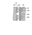
- FIG. 6 is a cross-sectional view showing a configuration of a main part of the hard disk device 1 shown in FIG.
- the tolerance ring 8 when the tolerance ring 8 is disposed between the carriage 5 and the pivot shaft 7, the curved portion 80 b comes into contact with the pivot shaft 7 and deforms. Due to the deformation of the curved portion 80b, the edge in the width direction of the cylindrical portion 80a is lifted with respect to the pivot shaft 7 (bearing 72). Due to the change in the contact state of the cylindrical portion 80a (convex portion 81) with respect to the pivot shaft 7, the load distribution in the central axis direction of the tolerance ring 8 (cylindrical portion 80a) is increased in the curved portion 80b, and the load applied to the bearing ball 72a is increased. Since it can reduce, the increase in the rotational resistance of the bearing ball 72a which arises when the bearing 72 is compressed can be suppressed.
- the rigidity of the bending portion 80b is determined by the radial position of the edge portion of the bending portion 80b, the protruding amount of the bending portion 80b in the radial direction, the axial length of the bending portion 80b, and the like.
- the load applied to the bearing 72 by the bending portion 80b increases, and the load required when the bearing 72 (pivot shaft 7) is inserted into the tolerance ring 8 when the hard disk device 1 is assembled. (Hereinafter, insertion load) also increases.
- the bending portion 80b is not limited to the shape shown in FIG. 5, and the bending portion 80b is set so that the load applied to the bearing 72 by the bending portion 80b and the insertion load of the bearing 72 (pivot shaft 7) have a desired value.
- the radial position of the edge portion, the protruding amount of the curved portion 80b in the radial direction, the axial length of the curved portion 80b, and the like may be appropriately changed.
- the tolerance ring 8 includes the following method as an example of a manufacturing method.
- a progressive press is used in which a predetermined pressing process is sequentially performed on a base material extending in a strip shape.
- the base material extending in a flat plate shape is subjected to a contouring process by a press so that the contour (outer edge) of the tolerance ring 8 is formed, and a base material that forms the contour of the tolerance ring 8 is formed.
- the connected state of the base material and the base material is maintained by the runner.
- the formation process of the curved part 80b and the formation process of the convex part 81 are performed with respect to the shape
- the convex portions 81 are respectively formed at the positions described above by pressing.
- a bending process is performed on the base material on which the bending portion 80b and the convex portion 81 are formed.
- the base material is bent and shaped stepwise so that the convex portion 81 is on the outer surface side along the longitudinal direction of the main surface of the base material from both ends.
- the tolerance ring 8 can be obtained by cutting off the base material from the runner. Note that after the trimming process, the obtained tolerance ring 8 may be subjected to a process (setting process) for applying a stress greater than the maximum usable stress.
- the base 80 is provided at each of the cylindrical portion 80a in which the convex portion 81 is formed and both ends in the width direction of the cylindrical portion 80a. Since the curved portion 80b having an arc shape toward the periphery (the direction opposite to the protruding direction of the convex portion 81) is provided, the bearing is maintained while maintaining the stability of fixation between the carriage 5 and the pivot shaft 7. It is possible to suppress a decrease in function.
- the bending portion 80b is provided at both ends in the width direction of the base portion 80 (cylindrical portion 80a), so that the pivot shaft 7 is supported at both ends in the width direction of the base portion 80.
- the inclination of the central axis of the tolerance ring 8 with respect to the central axis of the pivot shaft 7 can be more reliably suppressed.
- a sleeve in which a belt-shaped member circulates between the rod-shaped member and the bearing ball forms a substantially cylindrical shape. It was provided.
- the tolerance ring 8 can easily press-fit the pivot shaft 7 into the tolerance ring 8, and can pivot the carriage 5 and the pivot 5 by pressing against the wall surface of the connecting portion 52 of the convex portion 81.
- the space between the shaft 7 can be securely fixed.
- FIG. 7 is a perspective view showing a configuration of a tolerance ring 8a according to the first modification of the present embodiment.
- FIG. 8 is a cross-sectional view showing the configuration of the tolerance ring 8a, and is a cross-sectional view with a plane perpendicular to the central axis of the tolerance ring 8a as a cut surface.
- the curved portions 80b are provided at both ends of the cylindrical portion 80a.
- the cylindrical portion 80c has a base portion 801 provided with a curved portion 80d at the center. There may be.
- the curved portion 80d shown in Modification 1 has a curved shape similar to that of the curved portion 80b described above, and is between the rows of convex portions 81 arranged in two rows in the width direction of the cylindrical portion 80c, that is, in the circumferential direction of the cylindrical portion 80c. And it is the center part of the width direction orthogonal to radial direction, Comprising: It is provided along the circumference direction. Even in the configuration of the first modification, the same effects as those of the above-described embodiment can be obtained.
- the cross-section of the curved portion having a cut surface that is a plane orthogonal to the main surfaces of the base portions 80 and 801 is uniformly arcuate (continuously along the circumferential direction). However, it may be a part that protrudes in a part of the region like the convex part 81. In this case, a plurality of bending portions are provided along the circumferential direction.
- the curved portion at this time is arranged according to the position of the convex portion 81, and is provided, for example, in a region overlapping with the convex portion 81 when viewed along the width direction of the cylindrical portion 80a.
- the curved portions may be provided in a region that does not overlap the convex portion 81 when viewed along the width direction of the cylindrical portion 80a. It may be provided so as to extend over the convex portion 81. Further, when a plurality of curved portions are provided in a convex shape, it is preferable that each curved portion is arranged so as to be symmetric with respect to the central axis of the tolerance ring.
- the bending portion is described as being provided between the rows of the convex portions 81.
- the curved portion may protrude in a convex shape between the convex portions 81, or may extend in a convex shape in the width direction perpendicular to the circumferential direction.
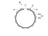
- FIG. 9 is a top view showing a configuration of a tolerance ring 8b according to the second modification of the present embodiment.
- the tolerance ring 8 b according to Modification 2 has different values of the radius of curvature of the end portions 82 and 83 in the circumferential direction and the radius of curvature of the portion other than the end portions 82 and 83 in the circumferential direction.
- the radius of curvature of the end portions 82 and 83 in the circumferential direction is equal to the radius of curvature of the connecting portion 52 of the carriage 5.
- the radius of curvature of the portion other than the end portions 82 and 83 in the circumferential direction is larger than the radius of curvature of the connecting portion 52 of the carriage 5.
- a broken line P 0 indicates a circular shape (a circumscribed circle shape) of a radius of curvature of a portion other than the end portions 82 and 83 in the circulation direction.
- the tolerance ring 8b is inserted into the connecting portion 52 of the carriage 5 and the open end portions 82 and 83 are closed, the shape along the circumferential direction is substantially equal to the curvature radius of the connecting portion 52.
- a circle with a radius can be formed.
- the tolerance ring 8 b is curved so that the radius of curvature continuously decreases in the direction from the portion other than the end portions 82 and 83 toward the end portions 82 and 83.
- the base material is bent so that the radius of curvature of the end portions 82 and 83 in the circumferential direction is smaller than the radius of curvature of the portion other than the end portions 82 and 83 in the circumferential direction.
- the base material is curved so that the radius of curvature decreases continuously (in a multistage manner) in a direction from the portion other than the end portions 82 and 83 toward the end portions 82 and 83.
- the radius of curvature of the end portions 82 and 83 in the circumferential direction is equal to the radius of curvature of the connecting portion 52 of the carriage 5, and the curvature radius of the portion other than the end portions 82 and 83 in the circumferential direction is the carriage 5. Therefore, the tolerance ring 8b is held inside the connecting portion 52 when inserted into the connecting portion 52 of the carriage 5, and the shape of the tolerance ring 8b in the circumferential direction is connected to the connecting portion 52. It can be a circle along the wall surface. For this reason, when inserting the tolerance ring 8b into the connecting portion 52 of the carriage 5, it can be inserted without damaging the wall surface of the connecting portion 52. Therefore, the occurrence of contamination due to insertion of the tolerance ring 8b can be suppressed.
- the conventional tolerance ring can be elastically deformed into a substantially circular shape whose shape along the circumferential direction is almost the same as the opening on the carriage side, but in reality, the tolerance ring is held in the carriage during the assembly work.
- the radius of curvature of the tolerance ring is designed to be larger than the radius of curvature of the carriage opening.
- the end side of the tolerance ring may be opened, and the radius of curvature of the end of the tolerance ring may be larger than the radius of curvature of the opening of the carriage.
- the insertion is performed without damaging the wall surface of the connecting portion 52 when inserted into the connecting portion 52. it can.
- the pivot shaft 7 when the pivot shaft 7 is press-fitted, the pivot shaft 7 can be press-fitted without damaging the inner peripheral surface of the tolerance ring 8b and / or the side surface of the pivot shaft 7. Therefore, the occurrence of contamination by the tolerance ring 8b can be further reliably suppressed.
- FIG. 10 is a perspective view schematically showing the configuration of the tolerance ring 8c according to the third modification of the present embodiment.
- the tolerance ring 8c according to the modified example 3 includes, in addition to the curved portion 80b and the convex portion 81 described above, two cutout portions 84a cut out in the width direction orthogonal to the circumferential direction (and the radial direction).
- the notch portion 84a includes an extending portion 841 extending in the width direction from the base end of the bending portion 80b (the edge in the width direction orthogonal to the circumferential direction and the radial direction of the base portion 80) to the cylindrical portion 80a, and the base end of the bending portion 80b.
- the cutout portion 84a includes the extending portion 841 extending in the width direction from the curved portion 80b to the cylindrical portion 80a, and at least the tip of the tip portion 842 is included in the formation region of the convex portion 81 in the circumferential direction of the cylindrical portion 80a. Preferably it is.
- the diameter of the tolerance ring becomes the diameter of the pivot shaft when the pivot shaft reaches the position where the convex portion is formed.
- the diameter is expanded along.
- the diameter of the ring formed by the base end on the pivot shaft insertion side is increased, and the diameter of the ring formed by the other base end is reduced by the reaction.
- the end on the opposite side to the insertion side rises. If the pivot shaft is further inserted from this state and the insertion is completed, the carriage shaft is rotated and inclined with respect to the central axis of the pivot shaft, which affects the assembly accuracy of the drive mechanism. .
- the notch 84a that is notched in the direction orthogonal to the circumferential direction (and the radial direction) of the base 80 of the tolerance ring 8c is provided.
- FIG. 11 is a perspective view schematically showing a configuration of a tolerance ring 8d according to the fourth modification of the present embodiment.
- the R-shaped diameter of the distal end portion 842 has been described as being equivalent to the length of the extending portion 841 in the circumferential direction.
- the tolerance ring 8d illustrated in FIG. It may be a notch 84b having a tip 843 having a diameter larger than the length of the base 80 in the circumferential direction at 841.
- FIG. 12 is a perspective view schematically showing a configuration of a tolerance ring 8e according to the fifth modification of the embodiment of the present invention.
- the notches 84a and 84b are described as being provided at both ends in the width direction of the tolerance ring.
- One or a plurality of (two in the fifth modification) may be provided on the side.
- the base end where the notch 84a is provided is the base end on the side different from the insertion side of the pivot shaft 7 of the tolerance ring 8e.
- the notch portion 84a is provided on one end side like the tolerance ring 8e according to the modified example 5
- the notch portion 84a is provided on the base end on the side different from the insertion side of the pivot shaft 7 of the tolerance ring 8e.
- the rotation suppression effect of 5 can be further increased.
- the notch portion 84a having a length of 1.0 mm is formed in the width direction (direction orthogonal to the circumferential direction), compared to the case where the notch portions 84a each having a length of 0.5 mm are formed at both ends, The effect of suppressing the rotation of the carriage 5 can be further increased when a 1.0 mm cutout is formed at one end (the base end on the side different from the insertion side of the pivot shaft 7).
- one or a plurality of cutout portions according to the modified examples 3 to 5 are provided at positions that equally divide the sides in the longitudinal direction. Further, when a plurality of notches are provided, the length of the extending portion 841 (the length in the direction orthogonal to the longitudinal direction of the tolerance ring) may be the same or different from each other. .
- the tolerance ring and the hard disk device according to the present invention are useful for suppressing deterioration of the function of the bearing while maintaining the stability of fixation between the carriage and the pivot shaft.
Landscapes
- Engineering & Computer Science (AREA)
- General Engineering & Computer Science (AREA)
- Mechanical Engineering (AREA)
- Moving Of Heads (AREA)
- Mounting Of Bearings Or Others (AREA)
Abstract
Dans l'anneau de tolérance (8) de l'invention, une pluralité de parties relief (81) en saillie dans une direction radiale à partir d'une face périphérique externe d'une partie base (80) dans laquelle un élément en forme de bande dessine sensiblement une boucle, lui donnant ainsi une forme d'anneau, est agencée suivant la direction périphérique de la partie base (80). La partie base (80) possède : une partie tubulaire (80a) qui prend sensiblement la forme d'un tube, et dans laquelle est agencée une partie relief (81) ; et une partie courbe (80b) qui est agencée suivant une direction périphérique dans une partie d'une direction de la direction périphérique de la partie tubulaire (80a) et d'une direction largeur croisant la direction radiale, et dans laquelle la face principale de la partie base (80) est courbée en forme de relief vers le côté périphérique interne de la partie tubulaire (80a).
Priority Applications (1)
| Application Number | Priority Date | Filing Date | Title |
|---|---|---|---|
| JP2014560788A JPWO2014123166A1 (ja) | 2013-02-05 | 2014-02-05 | トレランスリングおよびハードディスク装置 |
Applications Claiming Priority (2)
| Application Number | Priority Date | Filing Date | Title |
|---|---|---|---|
| JP2013020778 | 2013-02-05 | ||
| JP2013-020778 | 2013-02-05 |
Publications (1)
| Publication Number | Publication Date |
|---|---|
| WO2014123166A1 true WO2014123166A1 (fr) | 2014-08-14 |
Family
ID=51299758
Family Applications (1)
| Application Number | Title | Priority Date | Filing Date |
|---|---|---|---|
| PCT/JP2014/052699 Ceased WO2014123166A1 (fr) | 2013-02-05 | 2014-02-05 | Anneau de tolérance, et dispositif de disque dur |
Country Status (2)
| Country | Link |
|---|---|
| JP (1) | JPWO2014123166A1 (fr) |
| WO (1) | WO2014123166A1 (fr) |
Citations (4)
| Publication number | Priority date | Publication date | Assignee | Title |
|---|---|---|---|---|
| US4981390A (en) * | 1987-03-06 | 1991-01-01 | The Ray Engineering Co., Ltd. | Tolerance ring with retaining means |
| JP2012052638A (ja) * | 2010-09-03 | 2012-03-15 | Togo Seisakusho Corp | トルク伝達装置用トレランスリング |
| JP2012197927A (ja) * | 2011-03-04 | 2012-10-18 | Jtekt Corp | トルクリミッタ、伝達比可変装置及びトレランスリング |
| WO2012144628A1 (fr) * | 2011-04-22 | 2012-10-26 | 日本発條株式会社 | Bague tolérancée et procédé de fabrication d'une bague tolérancée |
-
2014
- 2014-02-05 WO PCT/JP2014/052699 patent/WO2014123166A1/fr not_active Ceased
- 2014-02-05 JP JP2014560788A patent/JPWO2014123166A1/ja active Pending
Patent Citations (4)
| Publication number | Priority date | Publication date | Assignee | Title |
|---|---|---|---|---|
| US4981390A (en) * | 1987-03-06 | 1991-01-01 | The Ray Engineering Co., Ltd. | Tolerance ring with retaining means |
| JP2012052638A (ja) * | 2010-09-03 | 2012-03-15 | Togo Seisakusho Corp | トルク伝達装置用トレランスリング |
| JP2012197927A (ja) * | 2011-03-04 | 2012-10-18 | Jtekt Corp | トルクリミッタ、伝達比可変装置及びトレランスリング |
| WO2012144628A1 (fr) * | 2011-04-22 | 2012-10-26 | 日本発條株式会社 | Bague tolérancée et procédé de fabrication d'une bague tolérancée |
Also Published As
| Publication number | Publication date |
|---|---|
| JPWO2014123166A1 (ja) | 2017-02-02 |
Similar Documents
| Publication | Publication Date | Title |
|---|---|---|
| JP6040167B2 (ja) | トレランスリング | |
| KR100463931B1 (ko) | 일정한 작은 설치력 프로파일을 가지는 공차 링 | |
| US7369368B1 (en) | Head stack assembly having an actuator body with multiple slots adjacent to a bore | |
| US6288878B1 (en) | Tolerance ring with high hoop strength to resist deformation | |
| JP5781628B2 (ja) | トレランスリング、ハードディスク装置およびハードディスク装置の製造方法 | |
| JP5787987B2 (ja) | トレランスリングおよびトレランスリングの製造方法 | |
| JP4553955B2 (ja) | ディスク回転駆動装置のクランプ及びクランプ製造方法 | |
| US9620158B2 (en) | Tolerance ring and hard disk device | |
| JP2004166497A (ja) | 薄型スピンドルモータ及びこれを備えるマイクロドライブ装置 | |
| JP6047106B2 (ja) | トレランスリングおよびハードディスク装置の製造方法 | |
| WO2014123166A1 (fr) | Anneau de tolérance, et dispositif de disque dur | |
| WO2013172313A1 (fr) | Anneau de tolérance | |
| KR100737531B1 (ko) | 스핀들 모터의 턴테이블 | |
| JP2005339716A (ja) | ディスク駆動装置およびこれを備えたディスク装置 | |
| US20060139800A1 (en) | Disk drive device, disk drive apparatus with the same, and method of manufacturing disk driving device | |
| JP2003303481A (ja) | ディスク装置のキャリッジサブアセンブリ | |
| JP4471301B2 (ja) | ディスク駆動装置および磁気ディスク装置 | |
| JP2001052401A (ja) | ディスク用調心装置およびこれを備えるディスク駆動用モータ | |
| JP2000050593A (ja) | スピンドルモータ | |
| US9908167B1 (en) | Disk drive tolerance ring with edge rounding from opposite major faces | |
| JPH07115752A (ja) | 形状記憶樹脂による極小モータのブラシ分け方法 | |
| JP2007265537A (ja) | ディスク回転駆動装置及びそのディスク取付方法、スプリング・ワッシャ |
Legal Events
| Date | Code | Title | Description |
|---|---|---|---|
| 121 | Ep: the epo has been informed by wipo that ep was designated in this application |
Ref document number: 14749574 Country of ref document: EP Kind code of ref document: A1 |
|
| ENP | Entry into the national phase |
Ref document number: 2014560788 Country of ref document: JP Kind code of ref document: A |
|
| NENP | Non-entry into the national phase |
Ref country code: DE |
|
| 122 | Ep: pct application non-entry in european phase |
Ref document number: 14749574 Country of ref document: EP Kind code of ref document: A1 |