WO2014123178A1 - チュービングポンプ - Google Patents
チュービングポンプ Download PDFInfo
- Publication number
- WO2014123178A1 WO2014123178A1 PCT/JP2014/052725 JP2014052725W WO2014123178A1 WO 2014123178 A1 WO2014123178 A1 WO 2014123178A1 JP 2014052725 W JP2014052725 W JP 2014052725W WO 2014123178 A1 WO2014123178 A1 WO 2014123178A1
- Authority
- WO
- WIPO (PCT)
- Prior art keywords
- tube
- pump
- valve
- cam
- pump block
- Prior art date
- Legal status (The legal status is an assumption and is not a legal conclusion. Google has not performed a legal analysis and makes no representation as to the accuracy of the status listed.)
- Ceased
Links
Images


Classifications
-
- F—MECHANICAL ENGINEERING; LIGHTING; HEATING; WEAPONS; BLASTING
- F04—POSITIVE - DISPLACEMENT MACHINES FOR LIQUIDS; PUMPS FOR LIQUIDS OR ELASTIC FLUIDS
- F04B—POSITIVE-DISPLACEMENT MACHINES FOR LIQUIDS; PUMPS
- F04B45/00—Pumps or pumping installations having flexible working members and specially adapted for elastic fluids
- F04B45/08—Pumps or pumping installations having flexible working members and specially adapted for elastic fluids having peristaltic action
-
- A—HUMAN NECESSITIES
- A61—MEDICAL OR VETERINARY SCIENCE; HYGIENE
- A61M—DEVICES FOR INTRODUCING MEDIA INTO, OR ONTO, THE BODY; DEVICES FOR TRANSDUCING BODY MEDIA OR FOR TAKING MEDIA FROM THE BODY; DEVICES FOR PRODUCING OR ENDING SLEEP OR STUPOR
- A61M5/00—Devices for bringing media into the body in a subcutaneous, intra-vascular or intramuscular way; Accessories therefor, e.g. filling or cleaning devices, arm rests
- A61M5/14—Infusion devices, e.g. infusing by gravity; Blood infusion; Accessories therefor
- A61M5/142—Pressure infusion, e.g. using pumps
-
- A—HUMAN NECESSITIES
- A61—MEDICAL OR VETERINARY SCIENCE; HYGIENE
- A61M—DEVICES FOR INTRODUCING MEDIA INTO, OR ONTO, THE BODY; DEVICES FOR TRANSDUCING BODY MEDIA OR FOR TAKING MEDIA FROM THE BODY; DEVICES FOR PRODUCING OR ENDING SLEEP OR STUPOR
- A61M5/00—Devices for bringing media into the body in a subcutaneous, intra-vascular or intramuscular way; Accessories therefor, e.g. filling or cleaning devices, arm rests
- A61M5/14—Infusion devices, e.g. infusing by gravity; Blood infusion; Accessories therefor
- A61M5/168—Means for controlling media flow to the body or for metering media to the body, e.g. drip meters, counters
- A61M5/16804—Active flow controllers
- A61M5/16813—Active flow controllers by controlling the degree of opening of the flow line
-
- A—HUMAN NECESSITIES
- A61—MEDICAL OR VETERINARY SCIENCE; HYGIENE
- A61M—DEVICES FOR INTRODUCING MEDIA INTO, OR ONTO, THE BODY; DEVICES FOR TRANSDUCING BODY MEDIA OR FOR TAKING MEDIA FROM THE BODY; DEVICES FOR PRODUCING OR ENDING SLEEP OR STUPOR
- A61M60/00—Blood pumps; Devices for mechanical circulatory actuation; Balloon pumps for circulatory assistance
- A61M60/20—Type thereof
- A61M60/247—Positive displacement blood pumps
- A61M60/253—Positive displacement blood pumps including a displacement member directly acting on the blood
- A61M60/268—Positive displacement blood pumps including a displacement member directly acting on the blood the displacement member being flexible, e.g. membranes, diaphragms or bladders
- A61M60/279—Peristaltic pumps, e.g. roller pumps
-
- F—MECHANICAL ENGINEERING; LIGHTING; HEATING; WEAPONS; BLASTING
- F04—POSITIVE - DISPLACEMENT MACHINES FOR LIQUIDS; PUMPS FOR LIQUIDS OR ELASTIC FLUIDS
- F04B—POSITIVE-DISPLACEMENT MACHINES FOR LIQUIDS; PUMPS
- F04B43/00—Machines, pumps, or pumping installations having flexible working members
- F04B43/08—Machines, pumps, or pumping installations having flexible working members having tubular flexible members
- F04B43/082—Machines, pumps, or pumping installations having flexible working members having tubular flexible members the tubular flexible member being pressed against a wall by a number of elements, each having an alternating movement in a direction perpendicular to the axes of the tubular member and each having its own driving mechanism
-
- F—MECHANICAL ENGINEERING; LIGHTING; HEATING; WEAPONS; BLASTING
- F04—POSITIVE - DISPLACEMENT MACHINES FOR LIQUIDS; PUMPS FOR LIQUIDS OR ELASTIC FLUIDS
- F04B—POSITIVE-DISPLACEMENT MACHINES FOR LIQUIDS; PUMPS
- F04B43/00—Machines, pumps, or pumping installations having flexible working members
- F04B43/12—Machines, pumps, or pumping installations having flexible working members having peristaltic action
-
- A—HUMAN NECESSITIES
- A61—MEDICAL OR VETERINARY SCIENCE; HYGIENE
- A61M—DEVICES FOR INTRODUCING MEDIA INTO, OR ONTO, THE BODY; DEVICES FOR TRANSDUCING BODY MEDIA OR FOR TAKING MEDIA FROM THE BODY; DEVICES FOR PRODUCING OR ENDING SLEEP OR STUPOR
- A61M5/00—Devices for bringing media into the body in a subcutaneous, intra-vascular or intramuscular way; Accessories therefor, e.g. filling or cleaning devices, arm rests
- A61M5/14—Infusion devices, e.g. infusing by gravity; Blood infusion; Accessories therefor
- A61M5/142—Pressure infusion, e.g. using pumps
- A61M5/14212—Pumping with an aspiration and an expulsion action
- A61M5/14228—Pumping with an aspiration and an expulsion action with linear peristaltic action, i.e. comprising at least three pressurising members or a helical member
-
- A—HUMAN NECESSITIES
- A61—MEDICAL OR VETERINARY SCIENCE; HYGIENE
- A61M—DEVICES FOR INTRODUCING MEDIA INTO, OR ONTO, THE BODY; DEVICES FOR TRANSDUCING BODY MEDIA OR FOR TAKING MEDIA FROM THE BODY; DEVICES FOR PRODUCING OR ENDING SLEEP OR STUPOR
- A61M60/00—Blood pumps; Devices for mechanical circulatory actuation; Balloon pumps for circulatory assistance
- A61M60/20—Type thereof
- A61M60/247—Positive displacement blood pumps
- A61M60/253—Positive displacement blood pumps including a displacement member directly acting on the blood
- A61M60/268—Positive displacement blood pumps including a displacement member directly acting on the blood the displacement member being flexible, e.g. membranes, diaphragms or bladders
- A61M60/279—Peristaltic pumps, e.g. roller pumps
- A61M60/284—Linear peristaltic pumps
Definitions
- the present invention is mainly used as a medical infusion pump, and relates to a tubing pump in which liquid in a tube that is detachably mounted is transferred by a pump mechanism.
- This shuttle-type infusion pump is, for example, disclosed in Patent Document 1 in which a tube is arranged between a V groove formed by an upper jaw (220) and a lower jaw (222) and a V groove of a shuttle (200), It is disclosed that the shuttle (200) is reciprocated so that the tube is repeatedly pressed.
- an upstream valve (412) is disposed on the upstream side of the shuttle (200), and a downstream valve (414) is disposed on the downstream side.
- the upstream valve (412) and the downstream valve (414) are interlocked with the reciprocating motion of the shuttle (200) and the infusion tube is closed or released from the closed state at an appropriate timing, the liquid in the infusion tube is transferred. Is done.
- the operating ranges of the shuttle (200), upstream valve (412), and downstream valve (414) are individually cam shapes for defining the operations of the shuttle (200), upstream valve (412), and downstream valve (414). Is defined by one cam (100) part.
- a tube is disposed between the V-groove of the V-groove-shaped fixing component (22) and the V-groove of the V-groove-shaped driving component (12A).
- the thing by the method of pressing a tube repeatedly is disclosed by reciprocating the groove-shaped drive component (12A).
- the shuttle-type infusion pump as shown in the cited document 1 and the cited document 2 is a peristaltic-type infusion that presses the infusion tube by a plurality of peristaltic movements as shown in Patent Document 3, for example. Compared to pumps, it achieves excellent flow accuracy.
- a first aspect for solving the above-described problem is a tubing pump for transferring liquid in a detachably mounted tube by a pump mechanism, wherein the pump mechanism is a valve for closing and opening the mounted tube. And a tube pressing mechanism that repeatedly presses the tube.
- the tube pressing mechanism includes a pump block that is movably held by at least two guide shafts, and the pump block continuously reciprocates. By operating, the tube is repeatedly pressed.
- the play of the drive unit can be prevented, so that the liquid in the infusion tube can be transferred with a more stable flow rate accuracy.
- the second aspect is the first aspect, wherein the tube pressing mechanism is disposed at a position facing the pump block, and an opposing part that does not operate when the liquid in the tube is transferred is disposed.
- a substantially V-shaped first groove is formed, and the opposing part is formed with a substantially V-shaped second groove, and when the pump block continuously reciprocates, the first The tube is repeatedly pressed between the second groove portion and the second groove portion.
- the deformed state of the tube due to pressing can be restored before being pressed again, so that the liquid in the infusion tube can be transferred with more stable flow accuracy. can do.
- a third aspect is the first aspect or the second aspect, wherein the valve mechanism is arranged on the upstream side and the downstream side, and the tube pressing mechanism includes the upstream side valve mechanism and the downstream side valve mechanism.
- the operation range of the pump block disposed in the tube pressing mechanism is determined by a pump cam, and the operation range of the upstream valve of the upstream valve mechanism is the first
- the operation range of the downstream valve of the downstream valve mechanism is determined by the second valve cam, and the pump cam, the first valve cam, and the second valve cam are Each is a separate cam part.
- valve opening / closing timing can be set more appropriately, so that the liquid in the infusion tube can be transferred with a more stable flow rate accuracy.
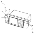
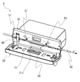
- FIG. 1 is an external perspective view of a tubing pump according to the present invention. It is an external appearance perspective view which shows the state which opened the front door of the tubing pump which concerns on this invention. It is a disassembled perspective view which shows the structure of the tubing pump which concerns on this invention.
- the tubing pump which concerns on this invention it is a figure which shows the positional relationship of a pump cam and a pump block. It is a figure which shows the cam shape of a pump cam in the tubing pump which concerns on this invention.
- the tubing pump concerning the present invention it is a chart figure showing operation timing of a pump block and a valve.
- FIGS. 1 to 8 correspond to this embodiment.
- the number of the reference drawing is described in parentheses when there is a drawing particularly suitable for reference with respect to the explanation portion.
- FIG. 1 and FIG. 2 are devices for forcing a liquid (for example, medicinal solution, nutrients, etc.) through a tube to inject it into a patient's body by applying a pump mechanism according to the present invention.
- the appearance of the tubing pump 1 is shown.
- the tubing pump 1 includes a door 20 that opens and closes the front portion of the pump body 10.
- FIG. 1 shows a state where the door 20 is closed
- FIG. 2 shows a state where the door 20 is opened.
- the pump body 10 is formed in a substantially rectangular box shape, and has an upright base 11 that is opened and closed by a door 20 on the front side, and a tube 30 clamped by a clamp device 40 on the base 11. Is inserted sideways (see FIG. 2). The clamp state of the tube 30 by the clamp device 40 is released when the door 20 is closed.
- the base 11 is a thick, substantially plate-like part, and includes a pump mechanism 50 for forcibly transferring the liquid in the attached tube 30.
- the pump mechanism 50 allows the liquid in the tube 30 to flow upstream by appropriately combining a pressing / releasing operation with respect to the attached tube 30, an opening / closing operation of the valve 51 on the upstream side, an opening / closing operation of the valve 52 on the downstream side, and the like. It is forcibly transferred in the direction d from the side to the downstream side (see FIG. 2).
- FIG. 3 is an exploded perspective view showing components of the pump mechanism 50.
- the pump mechanism 50 includes components such as an upstream valve 51, an upstream valve cam 51C, a downstream valve 52, a downstream valve cam 52C, a pump block 53, a pump block cam 53C, a guide shaft 53S, a shaft 54, and a pump block case 55. Has been.
- the tube pressing mechanism portion is formed with the pump block 53, the pump block cam 53C, and the guide shaft 53S as main components.
- the upstream side valve mechanism portion is formed in the pump mechanism 50 with the upstream side valve 51 and the upstream side valve cam 51C as main components. Further, the downstream side valve mechanism part is formed in the pump mechanism 50 with the downstream side valve 52 and the downstream side valve cam 52C as main components.
- the upstream valve cam 51C, the downstream valve cam 52C, and the pump block cam 53C are fixed to the shaft 54.
- the shaft 54 continuously rotates using an electric motor (not shown) as a power source.
- the upstream valve cam 51C, the downstream valve cam 52C, and the pump block cam 53C are within a certain range determined by the respective cam shapes on the upstream valve 51, the downstream valve 52, and the pump block 53, respectively. , Reciprocate.
- the tube pressing mechanism portion and the upstream and downstream valve mechanism portions work together to repeatedly press the tube 30 at an appropriate timing, and the tube 30 is closed or closed on the upstream and downstream sides. By releasing this, the liquid in the infusion tube is transferred.
- the tube pressing mechanism portion includes the pump block 53, the pump block cam 53C, and the guide shaft 53S.
- the position of the pump block 53 that reciprocates up and down is determined by the position of the pump block cam 53C that rotates about the shaft 54 as a rotation axis.
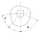
- FIG. 4 shows the cam shape of the pump block cam 53C.
- the cam surface of the pump block cam 53C having the cam shape shown in FIG. 4 contacts the upper bearing portion 53u or the lower bearing portion 53d of the pump block 53.
- the position of the pump block 53 is determined by the position.
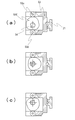
- FIG. 5A shows a positional relationship with the pump block cam 53C in a state where the pump block 53 is at the highest position.
- FIG. 5B shows the positional relationship with the pump block cam 53C in a state where the pump block 53 is in the intermediate position.
- FIG. 5C shows a positional relationship with the pump block cam 53C in a state where the pump block 53 is at the lowest position.
- the pump block 53 is held so as to be movable only in the vertical direction by being arranged through the guide shaft 53S in the ball bush portions 35b provided on the upstream side and the downstream side.
- the pump block 53 is formed with a V-groove 53v that is a substantially V-shaped recess, and the tube 30 is disposed along the V-groove 53v.
- the pump block facing component 21 having a substantially V-shaped concave portion is fixedly disposed at a position facing the pump block 53 when the door 20 is closed.
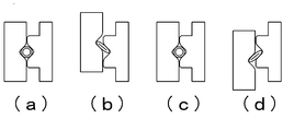
- the tube is arranged in a diamond-shaped space formed by the V groove 21v, which is a substantially V-shaped recess formed in the pump block facing part 21, facing the V groove 53v of the pump block 53. (See FIG. 6 (a) and FIG. 6 (c))
- the shape of the tube 30 is the elastic force of the material of the tube 30 and the tube Due to the pressure of the liquid flowing in 30, it tries to return to the state before being pressed.
- the infusion tube 30 is pushed from both sides by the inclined surface of the V-groove 53v and the inclined surface of the V-groove 21v, thereby restoring the shape of the tube.
- Cheap in addition to the elastic force of the material of the tube 30 and the pressure of the liquid, the infusion tube 30 is pushed from both sides by the inclined surface of the V-groove 53v and the inclined surface of the V-groove 21v, thereby restoring the shape of the tube.
- the valve mechanism section includes an upstream valve 51 and an upstream valve cam 51C on the upstream side, and includes a downstream valve 52 and a downstream valve cam 52C on the downstream side.
- the position of the valve 51 (52) that performs the operation of closing or releasing the tube 30 is determined by the position of the valve cam 51C (52C) that rotates around the shaft 54 as a rotation axis.
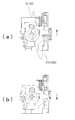
- FIG. 7A shows a positional relationship with the valve cam 51C (52C) in a state in which the valve 51 (52) is in a position where the tube 30 is not blocked.
- FIG. 7B shows a positional relationship with the valve cam 51C (52C) in a state where the valve 51 (52) is in a position where the tube 30 is closed.
- the upstream side valve 51 and the downstream side valve 52 are separate parts, a large movable part can be set and an ideal valve angle can be set, so that the flow rate accuracy as an infusion pump can be improved.
- FIG. 8 is a chart showing the operation timing of the pump block 53, the upstream valve 51, and the downstream valve 52 when the shaft 54 makes one rotation in the tubing pump 1 of this embodiment.
- the pump block 53 When the shaft 54 makes one rotation, the pump block 53 performs a reciprocating operation up and down. Further, when the shaft 54 makes one rotation, the upstream side valve 51 performs the operation of opening and closing the valve twice. At this time, the downstream valve 52 performs the operation of opening and closing the valve twice with a different timing from the upstream valve 51.
- FIG. 8 shows the relationship between these operations.
- 8 represents the movement displacement amount of the pump block 53, the upstream side valve 51, and the downstream side valve 52.
- the amount of movement when the valve opens to the maximum is set to 1, and the maximum amount of displacement that the pump block 53 moves upward or downward from the intermediate point is set to 3. .
- the pump block cam 53C operates the pump block 53 in the range of 44 ° indicated as F in FIG.
- the upstream valve 51 opens the infusion tube 30, and the downstream valve 52 closes the infusion tube 30.
- the pump block 53 moves toward the intermediate position, the liquid is sucked (Fill).
- the pump block cam 53C operates the pump block 53 within the range of 70 ° indicated as P in FIG.
- the upstream valve 51 closes the infusion tube 30, and the downstream valve 52 opens the infusion tube 30.
- the inclined surface of the V-groove 53v of the pump block 53 pushes the infusion tube 30 to discharge the liquid.
- the cams that change the operation directions of the pump block 53, the upstream valve 51, and the downstream valve 52 are used as separate cams, respectively, and as a result, the allowable range in design is expanded.
- the range could be set to 70 °.
- the cam angle range for discharge is set to 70 ° and the cam angle range for suction (Fill) is set to 44 °.
- Other angle ranges may be set according to the setting.
- one shaft 54 is used as a common rotation shaft for the pump block cam 53C, the upstream valve cam 51C, and the downstream valve cam 52C. May be.
- Tube 40 Clamp device 50: Pump mechanism 51: Upstream valve 51C: Upstream valve cam 52: Downstream valve 52C: Downstream valve cam 53: Pump block 53b: Ball bushing 53d: Lower bearing 53u: Upper bearing 53v: V groove 53S (guide pump) 53S: Guide shaft 54: Shaft
Landscapes
- Engineering & Computer Science (AREA)
- Health & Medical Sciences (AREA)
- Mechanical Engineering (AREA)
- General Engineering & Computer Science (AREA)
- Heart & Thoracic Surgery (AREA)
- Biomedical Technology (AREA)
- Hematology (AREA)
- Life Sciences & Earth Sciences (AREA)
- Animal Behavior & Ethology (AREA)
- General Health & Medical Sciences (AREA)
- Public Health (AREA)
- Veterinary Medicine (AREA)
- Anesthesiology (AREA)
- Vascular Medicine (AREA)
- Cardiology (AREA)
- Reciprocating Pumps (AREA)
- Infusion, Injection, And Reservoir Apparatuses (AREA)
Priority Applications (3)
| Application Number | Priority Date | Filing Date | Title |
|---|---|---|---|
| JP2014560797A JP5973002B2 (ja) | 2013-02-06 | 2014-02-06 | チュービングポンプ |
| CA2900336A CA2900336C (en) | 2013-02-06 | 2014-02-06 | Tubing pump |
| EP14748966.0A EP2955376B1 (de) | 2013-02-06 | 2014-02-06 | Schlauchpumpe |
Applications Claiming Priority (2)
| Application Number | Priority Date | Filing Date | Title |
|---|---|---|---|
| US13/760,794 US9217428B2 (en) | 2013-02-06 | 2013-02-06 | Tubing pump for delivering fluid in a tube |
| US13/760794 | 2013-02-06 |
Publications (1)
| Publication Number | Publication Date |
|---|---|
| WO2014123178A1 true WO2014123178A1 (ja) | 2014-08-14 |
Family
ID=51259357
Family Applications (1)
| Application Number | Title | Priority Date | Filing Date |
|---|---|---|---|
| PCT/JP2014/052725 Ceased WO2014123178A1 (ja) | 2013-02-06 | 2014-02-06 | チュービングポンプ |
Country Status (5)
| Country | Link |
|---|---|
| US (1) | US9217428B2 (de) |
| EP (1) | EP2955376B1 (de) |
| JP (1) | JP5973002B2 (de) |
| CA (1) | CA2900336C (de) |
| WO (1) | WO2014123178A1 (de) |
Cited By (1)
| Publication number | Priority date | Publication date | Assignee | Title |
|---|---|---|---|---|
| US10167861B2 (en) | 2016-05-26 | 2019-01-01 | Namiki Precision Singapore Pte. Ltd. | Infusion pump |
Families Citing this family (6)
| Publication number | Priority date | Publication date | Assignee | Title |
|---|---|---|---|---|
| EP2924289B1 (de) * | 2012-11-14 | 2019-08-14 | Adamant Namiki Precision Jewel Co., Ltd. | Schlauchpumpe |
| US20180140770A1 (en) * | 2015-06-01 | 2018-05-24 | Smiths Medical Asd, Inc. | Infusate tubing clamp systems for infusion pumps |
| US10366788B2 (en) * | 2016-08-22 | 2019-07-30 | Curlin Medical Inc. | Administration set detection and authentication using cam profiles |
| JP7767271B2 (ja) * | 2019-08-28 | 2025-11-11 | スミスズ メディカル エーエスディー,インコーポレイティド | 閉塞後のボーラス低減システム及び方法 |
| US11202859B2 (en) * | 2019-11-20 | 2021-12-21 | B Braun Medical Inc. | Cassette with free flow prevention for infusion pump |
| CN114129814B (zh) * | 2021-12-14 | 2023-06-23 | 北京信息科技大学 | 一种泵用输液器对输液精度的控制方法 |
Citations (8)
| Publication number | Priority date | Publication date | Assignee | Title |
|---|---|---|---|---|
| JPS5874881A (ja) * | 1981-10-28 | 1983-05-06 | Shimadzu Corp | 液体分注器 |
| US5151019A (en) * | 1988-11-04 | 1992-09-29 | Danby Medical Engineering Ltd. | Pumping device having inlet and outlet valves adjacent opposed sides of a tube deforming device |
| JPH05277183A (ja) | 1992-04-03 | 1993-10-26 | Sharp Corp | 輸液装置 |
| JPH11508017A (ja) | 1996-04-10 | 1999-07-13 | バクスター・インターナショナル・インコーポレイテッド | 容量注入ポンプ |
| US20030181865A1 (en) * | 2002-03-21 | 2003-09-25 | Kent Abrahamson | Pump and tube set thereof |
| WO2009133705A1 (ja) | 2008-04-30 | 2009-11-05 | 並木精密宝石株式会社 | 輸液ポンプ |
| WO2011082135A2 (en) * | 2009-12-31 | 2011-07-07 | Baxter International Inc. | Shuttle pump with controlled geometry |
| JP2013060813A (ja) * | 2011-09-12 | 2013-04-04 | Satoshi Konishi | ポンプ装置 |
Family Cites Families (12)
| Publication number | Priority date | Publication date | Assignee | Title |
|---|---|---|---|---|
| US2412397A (en) * | 1943-12-31 | 1946-12-10 | Lyndus E Harper | Flexible tube pump |
| US2689530A (en) * | 1950-06-26 | 1954-09-21 | Leo M Harvey | Machine for dispensing liquids |
| US3471079A (en) * | 1967-09-21 | 1969-10-07 | Elman B Myers | Reciprocating vacuum pump |
| US3606596A (en) * | 1970-04-14 | 1971-09-20 | Miles Lowell Edwards | Drug dispensing pump |
| SE380445B (sv) * | 1973-11-23 | 1975-11-10 | Bjoerklund K B | Forfarande for intermittent dosering av sma volymer samt anordning for genomforande av forfarandet |
| DE2746090A1 (de) * | 1977-10-13 | 1979-04-19 | Boehringer Mannheim Gmbh | Schlauchpumpe |
| US4936760A (en) * | 1989-06-12 | 1990-06-26 | Williams David R | Volumetric infusion pump |
| JP2547502Y2 (ja) * | 1989-09-13 | 1997-09-10 | 三和産業株式会社 | 圧送装置 |
| DE69013289T2 (de) * | 1989-11-02 | 1995-06-08 | Baxter Int | Pumpenvorrichtung. |
| US20030017066A1 (en) * | 2001-07-19 | 2003-01-23 | Baxter International Inc. | Apparatus, flexible bag and method for dispensing |
| ITBO20050203A1 (it) * | 2005-03-30 | 2006-09-30 | Medical Service S R L | Modulo monouso,pompa peristaltica,apparecchiatura per il trattamento del sangue e sistema costituito dall'associazione del modulo monouso e dell'apparecchiatura |
| US7998121B2 (en) * | 2009-02-06 | 2011-08-16 | Zevex, Inc. | Automatic safety occluder |
-
2013
- 2013-02-06 US US13/760,794 patent/US9217428B2/en active Active
-
2014
- 2014-02-06 CA CA2900336A patent/CA2900336C/en active Active
- 2014-02-06 WO PCT/JP2014/052725 patent/WO2014123178A1/ja not_active Ceased
- 2014-02-06 JP JP2014560797A patent/JP5973002B2/ja active Active
- 2014-02-06 EP EP14748966.0A patent/EP2955376B1/de not_active Not-in-force
Patent Citations (8)
| Publication number | Priority date | Publication date | Assignee | Title |
|---|---|---|---|---|
| JPS5874881A (ja) * | 1981-10-28 | 1983-05-06 | Shimadzu Corp | 液体分注器 |
| US5151019A (en) * | 1988-11-04 | 1992-09-29 | Danby Medical Engineering Ltd. | Pumping device having inlet and outlet valves adjacent opposed sides of a tube deforming device |
| JPH05277183A (ja) | 1992-04-03 | 1993-10-26 | Sharp Corp | 輸液装置 |
| JPH11508017A (ja) | 1996-04-10 | 1999-07-13 | バクスター・インターナショナル・インコーポレイテッド | 容量注入ポンプ |
| US20030181865A1 (en) * | 2002-03-21 | 2003-09-25 | Kent Abrahamson | Pump and tube set thereof |
| WO2009133705A1 (ja) | 2008-04-30 | 2009-11-05 | 並木精密宝石株式会社 | 輸液ポンプ |
| WO2011082135A2 (en) * | 2009-12-31 | 2011-07-07 | Baxter International Inc. | Shuttle pump with controlled geometry |
| JP2013060813A (ja) * | 2011-09-12 | 2013-04-04 | Satoshi Konishi | ポンプ装置 |
Non-Patent Citations (1)
| Title |
|---|
| See also references of EP2955376A4 |
Cited By (1)
| Publication number | Priority date | Publication date | Assignee | Title |
|---|---|---|---|---|
| US10167861B2 (en) | 2016-05-26 | 2019-01-01 | Namiki Precision Singapore Pte. Ltd. | Infusion pump |
Also Published As
| Publication number | Publication date |
|---|---|
| US9217428B2 (en) | 2015-12-22 |
| CA2900336A1 (en) | 2014-08-14 |
| JPWO2014123178A1 (ja) | 2017-02-02 |
| EP2955376A4 (de) | 2016-10-12 |
| JP5973002B2 (ja) | 2016-08-17 |
| EP2955376B1 (de) | 2020-12-16 |
| EP2955376A1 (de) | 2015-12-16 |
| CA2900336C (en) | 2021-05-04 |
| US20140219843A1 (en) | 2014-08-07 |
Similar Documents
| Publication | Publication Date | Title |
|---|---|---|
| JP5973002B2 (ja) | チュービングポンプ | |
| US9022755B2 (en) | Volumetric pump and its driving mechanism | |
| US7955060B2 (en) | Peristaltic pump | |
| JP5861341B2 (ja) | ポンプ装置 | |
| CN104039376B (zh) | 关于蠕动泵机构的系统和方法 | |
| US8944780B2 (en) | Pumping devices, systems including multiple pistons and methods for use with medical fluids | |
| CN101460742A (zh) | 包括驱动机构的容积泵 | |
| US20140170005A1 (en) | Liquid supply apparatus | |
| KR102267569B1 (ko) | 왕복동 펌프 | |
| JP2015086855A (ja) | プランジャポンプ | |
| KR101769787B1 (ko) | 무편심 정량펌프 | |
| KR102091581B1 (ko) | 스러스트 압력을 견디는 정량펌프 | |
| US8863644B2 (en) | Cam mechanism and liquid sending pump having same | |
| WO2019038108A1 (en) | ALTERNATIVE PUMP DRIVEN BY A CYLINDRICAL CAM | |
| CN102443977B (zh) | 供油泵及供油泵的阀装置 | |
| EP4477884B1 (de) | Quetschschlauchpumpe für den kontinuierlichen transfer und fluidtransferverfahren | |
| KR200482286Y1 (ko) | 사판식 유압모터의 각도조절장치 | |
| KR101725419B1 (ko) | 약물 주입을 위한 연동장치 | |
| JP3244287U (ja) | 輸液システム及び液体吐出安定化方法 | |
| CN202176471U (zh) | 微型电动超高压液压泵中柱塞的驱动装置 | |
| JP2016125413A (ja) | チューブポンプ | |
| CN120958235A (zh) | 泵送机构、泵以及操作泵的方法 | |
| JP2013070705A (ja) | 輸液ポンプ | |
| CN112840124A (zh) | 精确恒流的往复泵 | |
| JP2014231841A (ja) | 流体輸送装置 |
Legal Events
| Date | Code | Title | Description |
|---|---|---|---|
| 121 | Ep: the epo has been informed by wipo that ep was designated in this application |
Ref document number: 14748966 Country of ref document: EP Kind code of ref document: A1 |
|
| ENP | Entry into the national phase |
Ref document number: 2014560797 Country of ref document: JP Kind code of ref document: A |
|
| ENP | Entry into the national phase |
Ref document number: 2900336 Country of ref document: CA |
|
| NENP | Non-entry into the national phase |
Ref country code: DE |
|
| WWE | Wipo information: entry into national phase |
Ref document number: 2014748966 Country of ref document: EP |