WO2014125566A1 - Échangeur de chaleur du type à plaques et dispositif à cycle de réfrigération - Google Patents
Échangeur de chaleur du type à plaques et dispositif à cycle de réfrigération Download PDFInfo
- Publication number
- WO2014125566A1 WO2014125566A1 PCT/JP2013/053253 JP2013053253W WO2014125566A1 WO 2014125566 A1 WO2014125566 A1 WO 2014125566A1 JP 2013053253 W JP2013053253 W JP 2013053253W WO 2014125566 A1 WO2014125566 A1 WO 2014125566A1
- Authority
- WO
- WIPO (PCT)
- Prior art keywords
- fluid
- side inner
- flow path
- heat transfer
- inner fin
- Prior art date
- Legal status (The legal status is an assumption and is not a legal conclusion. Google has not performed a legal analysis and makes no representation as to the accuracy of the status listed.)
- Ceased
Links
Images



Classifications
-
- F—MECHANICAL ENGINEERING; LIGHTING; HEATING; WEAPONS; BLASTING
- F28—HEAT EXCHANGE IN GENERAL
- F28D—HEAT-EXCHANGE APPARATUS, NOT PROVIDED FOR IN ANOTHER SUBCLASS, IN WHICH THE HEAT-EXCHANGE MEDIA DO NOT COME INTO DIRECT CONTACT
- F28D9/00—Heat-exchange apparatus having stationary plate-like or laminated conduit assemblies for both heat-exchange media, the media being in contact with different sides of a conduit wall
- F28D9/0031—Heat-exchange apparatus having stationary plate-like or laminated conduit assemblies for both heat-exchange media, the media being in contact with different sides of a conduit wall the conduits for one heat-exchange medium being formed by paired plates touching each other
- F28D9/0043—Heat-exchange apparatus having stationary plate-like or laminated conduit assemblies for both heat-exchange media, the media being in contact with different sides of a conduit wall the conduits for one heat-exchange medium being formed by paired plates touching each other the plates having openings therein for circulation of at least one heat-exchange medium from one conduit to another
- F28D9/005—Heat-exchange apparatus having stationary plate-like or laminated conduit assemblies for both heat-exchange media, the media being in contact with different sides of a conduit wall the conduits for one heat-exchange medium being formed by paired plates touching each other the plates having openings therein for circulation of at least one heat-exchange medium from one conduit to another the plates having openings therein for both heat-exchange media
-
- F—MECHANICAL ENGINEERING; LIGHTING; HEATING; WEAPONS; BLASTING
- F28—HEAT EXCHANGE IN GENERAL
- F28F—DETAILS OF HEAT-EXCHANGE AND HEAT-TRANSFER APPARATUS, OF GENERAL APPLICATION
- F28F3/00—Plate-like or laminated elements; Assemblies of plate-like or laminated elements
- F28F3/02—Elements or assemblies thereof with means for increasing heat-transfer area, e.g. with fins, with recesses, with corrugations
- F28F3/025—Elements or assemblies thereof with means for increasing heat-transfer area, e.g. with fins, with recesses, with corrugations the means being corrugated, plate-like elements
- F28F3/027—Elements or assemblies thereof with means for increasing heat-transfer area, e.g. with fins, with recesses, with corrugations the means being corrugated, plate-like elements with openings, e.g. louvered corrugated fins; Assemblies of corrugated strips
-
- F—MECHANICAL ENGINEERING; LIGHTING; HEATING; WEAPONS; BLASTING
- F28—HEAT EXCHANGE IN GENERAL
- F28F—DETAILS OF HEAT-EXCHANGE AND HEAT-TRANSFER APPARATUS, OF GENERAL APPLICATION
- F28F3/00—Plate-like or laminated elements; Assemblies of plate-like or laminated elements
- F28F3/02—Elements or assemblies thereof with means for increasing heat-transfer area, e.g. with fins, with recesses, with corrugations
- F28F3/06—Elements or assemblies thereof with means for increasing heat-transfer area, e.g. with fins, with recesses, with corrugations the means being attachable to the element
-
- F—MECHANICAL ENGINEERING; LIGHTING; HEATING; WEAPONS; BLASTING
- F28—HEAT EXCHANGE IN GENERAL
- F28D—HEAT-EXCHANGE APPARATUS, NOT PROVIDED FOR IN ANOTHER SUBCLASS, IN WHICH THE HEAT-EXCHANGE MEDIA DO NOT COME INTO DIRECT CONTACT
- F28D21/00—Heat-exchange apparatus not covered by any of the groups F28D1/00 - F28D20/00
- F28D2021/0019—Other heat exchangers for particular applications; Heat exchange systems not otherwise provided for
- F28D2021/0068—Other heat exchangers for particular applications; Heat exchange systems not otherwise provided for for refrigerant cycles
Definitions
- the present invention relates to a plate heat exchanger and a refrigeration cycle apparatus.
- the present invention relates to an inner fin type plate heat exchanger or the like.
- JP 2003-185375 A page 5, FIG. 1
- Japanese Unexamined Patent Publication No. 2003-294382 page 4, FIG. 1
- JP 2003-056990 A page 5, FIG. 3
- the inner fin plate type heat exchanger as in Patent Document 1 has the following problems. For example, when heat exchange is performed between the first fluid (for example, refrigerant) and the second fluid (for example, water) and the first fluid is condensed from gas to liquid, a liquid film is formed on the wall surface of the fin on the second fluid side. It becomes easy to be done. Since the liquid film becomes a thermal resistance, the heat transfer coefficient has been lowered. Furthermore, when two types of fluids flow in adjacent flow paths, the shape of the flow paths is the same, so that only the characteristics of one of the fluids can be matched. Therefore, it has become impossible to design optimally in terms of heat transfer and strength.
- first fluid for example, refrigerant
- the second fluid for example, water
- the grooves are inclined with respect to the flow direction and are formed intermittently. For this reason, it is possible to hold a condensed liquid fluid (hereinafter referred to as “condensate”), but the liquid repellency is poor and the condensate becomes a thermal resistance.
- condensate a condensed liquid fluid
- the grooves are supported by the convex portions of each other, and the joining area of the adjacent heat transfer tubes is small and the strength is weak.
- channel is a cyclic
- the plate type heat exchanger according to the present invention has a passage hole serving as an outflow inlet for the first fluid and an outflow inlet for the second fluid.
- a heat transfer plate forming a second flow path through which the second fluid passes, a first fluid-side inner fin disposed in the first flow path for promoting heat transfer, and disposed in the second flow path, for heat transfer
- the first fluid fin has a convex portion protruding from the first flow path side to the second flow path side, and the surface serving as the first flow path in the heat transfer plate is
- the first fluid side inner fin has a concave portion matched with the convex portion.
- the first inner fin has a convex portion projecting to the second flow path side.
- the first fluid side inner fin has a liquid generated when the first fluid is condensed. It can hold
- FIG. 2 is a perspective view showing a partial cross section of the heat exchanger according to Embodiment 1.
- FIG. 3 is a diagram in which an upper second fluid side inner fin 9 is removed from FIG. 2.
- FIG. 6 is a perspective view showing a partial cross section of a second fluid side inner fin 9.
- FIG. 4 is a perspective view showing a partial cross section of a heat transfer plate 8. It is the figure which remove
- FIG. It is the figure which expanded a part of cross section of the heat exchanger in this Embodiment shown in FIG. It is a figure which shows the structure of the refrigerating-cycle apparatus which concerns on Embodiment 4 of this invention.
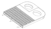
- FIG. 1 is a view showing a plate heat exchanger according to Embodiment 1 of the present invention.
- an inner fin type plate heat exchanger hereinafter referred to as a heat exchanger
- the upper side in each drawing will be described as the upper side
- the lower side will be described as the lower side.
- the first fluid is a refrigerant (for example, a fluid that changes phase by heat exchange)
- the second fluid is water.
- the first fluid inlet pipe 1, the first fluid outlet pipe 2, the first fluid outlet pipe 2, the first fluid outlet pipe 2, the first fluid outlet pipe 2, the first fluid outlet pipe 2, and the second fluid A two-fluid inflow pipe 3 and a second fluid outflow pipe 4 are provided.
- the side plate 5 which does not have the first fluid inflow pipe 1, the first fluid outflow pipe 2, the second fluid inflow pipe 3 and the second fluid outflow pipe 4 does not have a passage hole.
- the side plate 5 serves to reinforce the heat exchanger and increase the strength.
- the inner fin promotes heat transfer between the first fluid and the second fluid.
- the first fluid side inner fin 10 and the second fluid side inner fin 9 through which the second fluid flows are different in shape. The first fluid side inner fin 10 and the second fluid side inner fin 9 will be described later.
- a plurality of heat transfer plates 8 are stacked to form a flow path between the first fluid and the second fluid between the plates, and to exchange heat between the fluids.
- the direction from the passage hole communicating with the fluid inflow pipe to the passage hole communicating with the outflow pipe is the major axis direction (longitudinal direction), and the orthogonal direction is the minor axis direction (short direction).
- the first flow path and the second flow path are formed by laminating one or a plurality of heat transfer plates 8 between the pair of side plates 5.
- the first fluid side inner fins 10 and the second fluid side inner fins 9 are alternately sandwiched between the heat transfer plates 8.
- the heat transfer plate 8 of the present embodiment has irregularities corresponding to the shapes of the first fluid side inner fin 10 and the second fluid side inner fin 9.
- the first fluid-side inner fin 10 and the second fluid-side inner fin 9 have different heights (directions perpendicular to the direction in which the fluid flows)
- two types of heat transfer plates 8 matched to the height are used. have.
- it has a passage hole corresponding to the 1st fluid inflow pipe 1, the 1st fluid outflow pipe 2, the 2nd fluid inflow pipe 3, and the 2nd fluid outflow pipe 4.
- the flow direction of the first fluid be X and let the flow direction of the second fluid be Y. From FIG. 1, in the flow path formed in the heat transfer plate 8, the flow direction of the refrigerant in the first fluid and the second fluid is the opposite flow.
- FIG. 2 is a perspective view showing a partial cross section of the heat exchanger according to Embodiment 1 of the present invention.
- the heat transfer plate 8, the second fluid side inner fin 9, the heat transfer plate 8, the first fluid side inner fin 10, the heat transfer plate 8, and the second fluid side inner fin 9 are stacked in this order from the lower side. The figure is shown.
- FIG. 3 is a view obtained by removing the upper second fluid side inner fin 9 from FIG.
- FIG. 4 is a perspective view showing a cross section of a part of the second fluid side inner fin 9.
- FIG. 5 is a perspective view showing a partial cross section of the heat transfer plate 8.
- FIG. 6 is a view obtained by removing the heat transfer plate 8 from FIG.
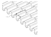
- FIG. 7 is a perspective view showing a partial cross section of the first fluid-side inner fin 10.
- FIG. 8 is an enlarged view of a part of the cross section of the heat exchanger in the present embodiment shown in FIG.
- the first fluid-side inner fin 10 has a protruding portion that protrudes toward the second flow path.
- corrugation is also formed in the heat-transfer plate 8.
- FIG. The concave portion of the heat transfer plate 8 corresponds to the convex portion of the first fluid-side inner fin 10. For this reason, the convex part when viewed from the first flow path side becomes a concave part on the second fluid side.
- the first fluid-side inner fin 10 Since the first fluid-side inner fin 10 has the convex portion, when the first fluid passes through the first flow path and condenses, a liquid film (condensed liquid film) formed by condensation is converted into the first fluid-side inner fin 10. It is made to concentrate on the convex part. For this reason, the condensate film formed on the wall surface of the first fluid-side inner fin 10 other than the convex portion and the wall surface of the heat transfer plate 8 can be thinned, and the heat transfer coefficient can be improved.
- the second fluid-side inner fin 9 is also formed with a convex portion.
- the arrangement of the inner fins may be parallel or orthogonal to the fluid flow direction.
- the heat transfer plate 8 and the protrusions formed on each inner fin may be formed so as to be linear along the fluid flow direction.
- the convex portion is formed from the passage hole communicating with the first fluid inflow pipe 1 toward the passage hole communicating with the first fluid outflow pipe 2 along the fluid flow direction (long axis direction). The first fluid that has been condensed and turned into a liquid is concentrated on the convex portion and flows down, so that the liquid spillability from the fin wall surface is improved and the heat transfer rate is improved.
- the heat transfer coefficient is improved by holding the condensate in the convex portion of the first fluid-side inner fin 10 and activating nucleate boiling between adjacent bubbles.
- the convex portions protruding into the flow paths promote local disturbance of the fluid, and compared to the case where the inner fin and heat transfer plate surfaces are flat, The heat transfer coefficient can be improved.
- by forming convex portions on the first fluid-side inner fin 10 and the second fluid-side inner fin 9 it is possible to increase the effective heat transfer area and further increase the amount of heat exchange.
- the convex portions of the first fluid-side inner fin 10 and the second fluid-side inner fin 9 can be fitted by forming the heat transfer plate 8 to be uneven, an offset type heat exchange having a flat surface is possible. Compared with a vessel, the bonding strength can be greatly improved. Thereby, the plate
- FIG. 5 Although not particularly shown in the first embodiment, the arrangement of the heat transfer plate 8 having a convex portion and a concave portion will be described in the present embodiment.
- the convex portions are arranged at equal intervals in the short axis direction.
- the dimension s which is the interval between the convex portions of the first fluid-side inner fin 10 and the interval t between the convex portions of the heat transfer plate 8 are each in the minor axis direction. Are arranged at equal intervals with the same length.
- corrugation of the heat-transfer plate 8 corresponding to the 1st fluid side inner fin 10 can be formed with the same kind of metal mold
- the interval between the convex portions of the second fluid side inner fin 9 and the interval between the convex portions of the heat transfer plate 8 are equally spaced in the minor axis direction.
- the unevenness of the two-fluid-side inner fins 9 and the unevenness of the heat transfer plate 8 corresponding to the second fluid-side inner fins 9 can be formed by the same type (two types in total, one type each).
- the interval between the convex portions of the first fluid-side inner fin 10 and the interval between the convex portions of the second fluid-side inner fin 9 are the same. There is no need to make the heat transfer plate 8. For this reason, in addition to the effect of Embodiment 1, a heat exchanger can be obtained more inexpensively.
- Embodiment 3 the convex portion of the first fluid-side inner fin 10 will be described.
- the convex portions and concave portions of the first fluid-side inner fin 10 are arranged in a staggered manner.
- the unevenness of the heat transfer plate 8 can be fitted so that a plurality of rows of protrusions can be fitted.
- corrugation of the heat-transfer plate 8 is formed so that the convex part for 2 rows of the 1st fluid side inner fin 10 can be fitted by one recessed part.
- the convex portion of the first fluid-side inner fin 10 when the convex portion of the first fluid-side inner fin 10 is set to s1 that is 1 ⁇ 2 of the dimension s, the convex portion of the first fluid-side inner fin 10 becomes the concave portion of the heat transfer plate 8. It will fit. For this reason, the 1st fluid side inner fin 10 and the heat-transfer plate 8, and the 2nd fluid side inner fin 9 and the heat-transfer plate 8 can each be created with 1 type (total 3 types) metal mold
- the first fluid-side inner fin 10 may be used as long as pressure loss and manufacturing restrictions of the first fluid are not exceeded.
- the number of convex portions may be divided.
- the first fluid-side inner fin 10 is arranged so that the direction u is the flow direction X, but may be arranged so that the direction s is the flow direction X. Similar effects can be obtained.
- the second fluid-side inner fin 9 is arranged so that the direction of v is the flow direction Y, but is arranged so that the direction of t is the flow direction X. The same effect can be obtained.
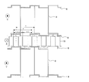
- FIG. 9 is a diagram showing a configuration of a refrigeration cycle apparatus according to Embodiment 4 of the present invention.
- a refrigerant circuit (refrigerant circulation circuit) is configured by connecting a compressor 21, a condenser (including a gas cooler) 22, an expansion device 23, and an evaporator 24.
- the blower 25 drives the blower motor 26 to form an air flow in order to promote heat exchange between the refrigerant passing through the evaporator 24 and the air.
- Compressor 21 sucks in refrigerant, compresses it, discharges it in a high temperature / high pressure state.
- it may be configured by a compressor of a type that can control the number of revolutions by an inverter circuit or the like and adjust the discharge amount of the refrigerant.
- the condenser 22 having the heat exchanger described in the first embodiment or the like performs heat exchange between, for example, water (second fluid) flowing through the water circuit 27 and the refrigerant (first fluid) to condense the refrigerant. To make a liquid refrigerant (condensed liquid).
- the expansion device 23 expands the refrigerant by decompressing it.
- a flow rate control means such as an electronic expansion valve, but may be constituted by an expansion valve having a temperature sensing cylinder, a refrigerant flow rate adjustment means such as a capillary tube (capillary), or the like.
- the evaporator 24 evaporates the refrigerant by exchanging heat with air or the like to form a gas (gas) -like refrigerant (evaporation gasification).
- the heat exchanger described in Embodiments 1 to 3 can be used for the evaporator 24.
- heat transfer performance can be improved by using the heat exchanger described in the first to third embodiments. By improving the heat transfer performance, an energy-efficient and energy-saving refrigeration cycle apparatus can be obtained.
- Heating energy efficiency indoor heat exchanger (condenser) capacity / total input
- Cooling energy efficiency indoor heat exchanger (evaporator) capacity / total input
- the compressor 21 sucks the refrigerant, compresses it, and discharges it in a high temperature / high pressure state.
- the discharged refrigerant flows into the condenser 22.
- the condenser 22 performs heat exchange between the water flowing through the water circuit 27 and the refrigerant to condense and liquefy the refrigerant.
- the condensed and liquefied refrigerant passes through the expansion device 23.
- the expansion device 23 depressurizes the condensed and liquefied refrigerant that passes therethrough.
- the decompressed refrigerant flows into the evaporator 24.
- the evaporator 24 exchanges heat between the air supplied from the blower 25 and the refrigerant, and evaporates the refrigerant.
- the compressor 21 sucks the evaporated gas refrigerant.
- the refrigeration cycle apparatus described above includes HCFC (R22) and HFC (R116, R125, R134a, R14, R143a, R152a, R227ea, R23, R236ea, R236fa, R245ca, R245fa, R32, R41, RC318, etc.
- the effect can be achieved more efficiently in R410A, R410A, and R32 whose design pressure and physical property values are close.
- the refrigerant and the oil dissolve, such as mineral oil, alkylbenzene oil, ester oil, ether oil, and fluorine oil.
- the effect can be achieved with any refrigeration oil, whether or not.
- the present invention is not particularly limited to the above-described embodiments, and can be combined as appropriate. Moreover, as an application example of the present invention, for example, the present invention can be used for many industrial and household equipment equipped with a plate heat exchanger such as air conditioning, power generation, and food sterilization equipment.
Landscapes
- Engineering & Computer Science (AREA)
- Physics & Mathematics (AREA)
- Thermal Sciences (AREA)
- Mechanical Engineering (AREA)
- General Engineering & Computer Science (AREA)
- Heat-Exchange Devices With Radiators And Conduit Assemblies (AREA)
Abstract
L'invention porte sur un échangeur de chaleur du type à plaques, lequel échangeur comporte : une pluralité de plaques de transfert de chaleur rectangulaires (8) qui comprennent un trou de passage jouant le rôle d'entrée/sortie pour un premier fluide et un second fluide, et qui sont empilées de façon à former une première trajectoire d'écoulement à travers laquelle passe le premier fluide et une seconde trajectoire d'écoulement à travers laquelle passe le second fluide ; une première ailette interne côté fluide (10) qui est disposée dans la première trajectoire d'écoulement et qui accélère le transfert de chaleur ; et une seconde ailette interne côté fluide (9) qui est disposée dans la seconde trajectoire d'écoulement et qui accélère le transfert de chaleur. La première ailette interne côté fluide (10) comprend une saillie qui fait saillie sur le côté de seconde trajectoire d'écoulement le long de la direction dans laquelle s'écoule le premier fluide dans la première trajectoire d'écoulement. Dans les plaques de transfert de chaleur (8), la surface jouant le rôle de première trajectoire d'écoulement comprend un creux qui correspond à la saillie de l'ailette interne côté premier fluide (10).
Priority Applications (3)
| Application Number | Priority Date | Filing Date | Title |
|---|---|---|---|
| PCT/JP2013/053253 WO2014125566A1 (fr) | 2013-02-12 | 2013-02-12 | Échangeur de chaleur du type à plaques et dispositif à cycle de réfrigération |
| JP2015500018A JPWO2014125566A1 (ja) | 2013-02-12 | 2013-02-12 | プレート式熱交換器及び冷凍サイクル装置 |
| CN201420062584.0U CN203758092U (zh) | 2013-02-12 | 2014-02-12 | 板式换热器及制冷循环装置 |
Applications Claiming Priority (1)
| Application Number | Priority Date | Filing Date | Title |
|---|---|---|---|
| PCT/JP2013/053253 WO2014125566A1 (fr) | 2013-02-12 | 2013-02-12 | Échangeur de chaleur du type à plaques et dispositif à cycle de réfrigération |
Publications (1)
| Publication Number | Publication Date |
|---|---|
| WO2014125566A1 true WO2014125566A1 (fr) | 2014-08-21 |
Family
ID=51253354
Family Applications (1)
| Application Number | Title | Priority Date | Filing Date |
|---|---|---|---|
| PCT/JP2013/053253 Ceased WO2014125566A1 (fr) | 2013-02-12 | 2013-02-12 | Échangeur de chaleur du type à plaques et dispositif à cycle de réfrigération |
Country Status (3)
| Country | Link |
|---|---|
| JP (1) | JPWO2014125566A1 (fr) |
| CN (1) | CN203758092U (fr) |
| WO (1) | WO2014125566A1 (fr) |
Cited By (9)
| Publication number | Priority date | Publication date | Assignee | Title |
|---|---|---|---|---|
| EP2998676A1 (fr) * | 2014-09-17 | 2016-03-23 | VALEO AUTOSYSTEMY Sp. Z. o.o. | Échangeur de chaleur, notamment un condensateur |
| FR3045801A1 (fr) * | 2015-12-21 | 2017-06-23 | Valeo Systemes Thermiques | Echangeur thermique, notamment pour vehicule automobile |
| JP2019078441A (ja) * | 2017-10-24 | 2019-05-23 | 株式会社日阪製作所 | プレート式熱交換器 |
| CN111271996A (zh) * | 2020-03-23 | 2020-06-12 | 江苏唯益换热器有限公司 | 一种具有非对称通道的板式换热器 |
| CN111351387A (zh) * | 2018-12-21 | 2020-06-30 | 因诺黑特瑞典公司 | 热交换器板和热交换器 |
| JPWO2021149139A1 (fr) * | 2020-01-21 | 2021-07-29 | ||
| US20220155019A1 (en) * | 2019-06-03 | 2022-05-19 | Mitsubishi Electric Corporation | Plate heat exchanger and heat transfer apparatus |
| WO2022108450A1 (fr) * | 2020-11-20 | 2022-05-27 | Level Holding Ii B.V. | Récupérateur à configuration de canal améliorée |
| WO2024253170A1 (fr) * | 2023-06-06 | 2024-12-12 | ダイキン工業株式会社 | Échangeur de chaleur et son procédé de fabrication |
Families Citing this family (3)
| Publication number | Priority date | Publication date | Assignee | Title |
|---|---|---|---|---|
| IL255877B (en) | 2017-11-23 | 2019-12-31 | Dulberg Sharon | A device for extracting water from the air, and for drying the air using high energy and methods for its production |
| JP7256951B2 (ja) * | 2018-10-29 | 2023-04-13 | 株式会社ノーリツ | プレート式熱交換器およびこれを備えた温水装置 |
| EP3686260B1 (fr) * | 2019-01-23 | 2022-12-28 | Weiss Technik GmbH | Agent réfrigérant |
Citations (5)
| Publication number | Priority date | Publication date | Assignee | Title |
|---|---|---|---|---|
| JP2002174495A (ja) * | 2000-12-07 | 2002-06-21 | Matsushita Electric Ind Co Ltd | 熱交換器 |
| JP2003075088A (ja) * | 2001-08-28 | 2003-03-12 | Mitsubishi Electric Corp | 冷却フィン構造 |
| JP2005069499A (ja) * | 2003-08-25 | 2005-03-17 | Nissan Motor Co Ltd | プレートフィン式熱交換器 |
| JP2009079779A (ja) * | 2007-09-25 | 2009-04-16 | Mitsubishi Electric Corp | プレート式熱交換器及びこのプレート式熱交換器を用いた空気調和装置 |
| JP2009150587A (ja) * | 2007-12-19 | 2009-07-09 | Denso Corp | 熱交換器 |
Family Cites Families (8)
| Publication number | Priority date | Publication date | Assignee | Title |
|---|---|---|---|---|
| US2782009A (en) * | 1952-03-14 | 1957-02-19 | Gen Motors Corp | Heat exchangers |
| JP2660207B2 (ja) * | 1987-11-25 | 1997-10-08 | 株式会社荏原シンワ | 間接型熱交換器の製造方法 |
| JPH08204074A (ja) * | 1995-01-30 | 1996-08-09 | Calsonic Corp | ヒートシンク及びその製造方法 |
| JP2003056990A (ja) * | 2001-08-16 | 2003-02-26 | Sasakura Engineering Co Ltd | プレート型蒸発装置 |
| JP2003185375A (ja) * | 2001-12-17 | 2003-07-03 | Daikin Ind Ltd | プレート式熱交換器 |
| JP2003185377A (ja) * | 2001-12-18 | 2003-07-03 | Nissan Motor Co Ltd | プレートフィン式熱交換器 |
| JP2003294382A (ja) * | 2002-04-04 | 2003-10-15 | Toyo Radiator Co Ltd | 熱交換器 |
| US9448013B2 (en) * | 2011-04-18 | 2016-09-20 | Mitsubishi Electric Corporation | Plate heat exchanger and heat pump apparatus |
-
2013
- 2013-02-12 JP JP2015500018A patent/JPWO2014125566A1/ja active Pending
- 2013-02-12 WO PCT/JP2013/053253 patent/WO2014125566A1/fr not_active Ceased
-
2014
- 2014-02-12 CN CN201420062584.0U patent/CN203758092U/zh not_active Expired - Lifetime
Patent Citations (5)
| Publication number | Priority date | Publication date | Assignee | Title |
|---|---|---|---|---|
| JP2002174495A (ja) * | 2000-12-07 | 2002-06-21 | Matsushita Electric Ind Co Ltd | 熱交換器 |
| JP2003075088A (ja) * | 2001-08-28 | 2003-03-12 | Mitsubishi Electric Corp | 冷却フィン構造 |
| JP2005069499A (ja) * | 2003-08-25 | 2005-03-17 | Nissan Motor Co Ltd | プレートフィン式熱交換器 |
| JP2009079779A (ja) * | 2007-09-25 | 2009-04-16 | Mitsubishi Electric Corp | プレート式熱交換器及びこのプレート式熱交換器を用いた空気調和装置 |
| JP2009150587A (ja) * | 2007-12-19 | 2009-07-09 | Denso Corp | 熱交換器 |
Cited By (18)
| Publication number | Priority date | Publication date | Assignee | Title |
|---|---|---|---|---|
| EP2998676A1 (fr) * | 2014-09-17 | 2016-03-23 | VALEO AUTOSYSTEMY Sp. Z. o.o. | Échangeur de chaleur, notamment un condensateur |
| WO2016042047A1 (fr) * | 2014-09-17 | 2016-03-24 | Valeo Autosystemy Sp. Z.O.O. | Échangeur de chaleur, en particulier condensateur |
| US20170241686A1 (en) * | 2014-09-17 | 2017-08-24 | Valeo Autosystemy Sp. Z O.O. | Heat exchanger, in particular a condenser |
| US10352598B2 (en) | 2014-09-17 | 2019-07-16 | Valeo Autosystemy Sp. Z O.O. | Heat exchanger, in particular a condenser |
| FR3045801A1 (fr) * | 2015-12-21 | 2017-06-23 | Valeo Systemes Thermiques | Echangeur thermique, notamment pour vehicule automobile |
| WO2017109348A1 (fr) * | 2015-12-21 | 2017-06-29 | Valeo Systemes Thermiques | Échangeur thermique, notamment pour véhicule automobile |
| JP2019078441A (ja) * | 2017-10-24 | 2019-05-23 | 株式会社日阪製作所 | プレート式熱交換器 |
| CN111351387A (zh) * | 2018-12-21 | 2020-06-30 | 因诺黑特瑞典公司 | 热交换器板和热交换器 |
| US11898805B2 (en) | 2018-12-21 | 2024-02-13 | Innoheat Sweden Ab | Heat exchanger plate and heat exchanger |
| US20220155019A1 (en) * | 2019-06-03 | 2022-05-19 | Mitsubishi Electric Corporation | Plate heat exchanger and heat transfer apparatus |
| US12044483B2 (en) * | 2019-06-03 | 2024-07-23 | Mitsubishi Electric Corporation | Plate heat exchanger and heat transfer apparatus |
| JPWO2021149139A1 (fr) * | 2020-01-21 | 2021-07-29 | ||
| JP7292435B2 (ja) | 2020-01-21 | 2023-06-16 | 三菱電機株式会社 | プレート式熱交換器及び伝熱装置 |
| CN111271996A (zh) * | 2020-03-23 | 2020-06-12 | 江苏唯益换热器有限公司 | 一种具有非对称通道的板式换热器 |
| WO2022108450A1 (fr) * | 2020-11-20 | 2022-05-27 | Level Holding Ii B.V. | Récupérateur à configuration de canal améliorée |
| WO2024253170A1 (fr) * | 2023-06-06 | 2024-12-12 | ダイキン工業株式会社 | Échangeur de chaleur et son procédé de fabrication |
| JP2024175686A (ja) * | 2023-06-06 | 2024-12-18 | ダイキン工業株式会社 | 熱交換器及び熱交換器の製造方法 |
| JP7678386B2 (ja) | 2023-06-06 | 2025-05-16 | ダイキン工業株式会社 | 熱交換器及び熱交換器の製造方法 |
Also Published As
| Publication number | Publication date |
|---|---|
| CN203758092U (zh) | 2014-08-06 |
| JPWO2014125566A1 (ja) | 2017-02-02 |
Similar Documents
| Publication | Publication Date | Title |
|---|---|---|
| CN203758092U (zh) | 板式换热器及制冷循环装置 | |
| US9482445B2 (en) | Heat pump water heater with heat utilization balance processor and heat utilization balance processor thereof | |
| JP6042026B2 (ja) | 冷凍サイクル装置 | |
| JP6016935B2 (ja) | プレート式熱交換器及びこのプレート式熱交換器を備えた冷凍サイクル装置 | |
| JP6214670B2 (ja) | 熱交換器及びその熱交換器を用いた冷凍サイクル装置 | |
| WO2014147804A1 (fr) | Échangeur de chaleur du type à plaques et dispositif de cycle de réfrigération le comportant | |
| WO2015132963A1 (fr) | Échangeur thermique et climatiseur | |
| KR20150010826A (ko) | 공기조화기 및 이중관 열교환기 | |
| KR20140142802A (ko) | 실외 열교환기 및 공기조화기 | |
| JP5646257B2 (ja) | 冷凍サイクル装置 | |
| JP5627635B2 (ja) | 空気調和機 | |
| CN108020106B (zh) | 用作经济器的板式换热器 | |
| KR20130023487A (ko) | 마이크로 채널 열교환기를 갖는 히트펌프용 증발기 | |
| JP5171983B2 (ja) | 熱交換器及び冷凍サイクル装置 | |
| JP6038186B2 (ja) | 熱交換器及び冷凍サイクル装置 | |
| JP2002228380A (ja) | 熱交換器、および冷却装置 | |
| JP5404729B2 (ja) | 熱交換器及び冷凍サイクル装置 | |
| JP4983878B2 (ja) | 熱交換器及びこの熱交換器を備えた冷蔵庫、空気調和機 | |
| JP6469489B2 (ja) | 冷凍サイクル装置 | |
| US12339066B2 (en) | Microchannel heat exchanger with varying fin density | |
| JP2010078256A (ja) | フィンチューブ型熱交換器、これを用いた冷凍サイクル装置及び空気調和機 | |
| JP2003004396A (ja) | 熱交換器および冷凍空調装置 | |
| KR100731389B1 (ko) | 열교환기 | |
| KR20210097467A (ko) | 히트 펌프 시스템의 전열관 | |
| Khan et al. | Analysis of Condenser under Various Refrigerants |
Legal Events
| Date | Code | Title | Description |
|---|---|---|---|
| 121 | Ep: the epo has been informed by wipo that ep was designated in this application |
Ref document number: 13875166 Country of ref document: EP Kind code of ref document: A1 |
|
| ENP | Entry into the national phase |
Ref document number: 2015500018 Country of ref document: JP Kind code of ref document: A |
|
| NENP | Non-entry into the national phase |
Ref country code: DE |
|
| 122 | Ep: pct application non-entry in european phase |
Ref document number: 13875166 Country of ref document: EP Kind code of ref document: A1 |