WO2014125644A1 - 再生可能エネルギ発電装置 - Google Patents
再生可能エネルギ発電装置 Download PDFInfo
- Publication number
- WO2014125644A1 WO2014125644A1 PCT/JP2013/053857 JP2013053857W WO2014125644A1 WO 2014125644 A1 WO2014125644 A1 WO 2014125644A1 JP 2013053857 W JP2013053857 W JP 2013053857W WO 2014125644 A1 WO2014125644 A1 WO 2014125644A1
- Authority
- WO
- WIPO (PCT)
- Prior art keywords
- renewable energy
- rotating shaft
- segment
- cam surface
- piston
- Prior art date
- Legal status (The legal status is an assumption and is not a legal conclusion. Google has not performed a legal analysis and makes no representation as to the accuracy of the status listed.)
- Ceased
Links
Images







Classifications
-
- F—MECHANICAL ENGINEERING; LIGHTING; HEATING; WEAPONS; BLASTING
- F04—POSITIVE - DISPLACEMENT MACHINES FOR LIQUIDS; PUMPS FOR LIQUIDS OR ELASTIC FLUIDS
- F04B—POSITIVE-DISPLACEMENT MACHINES FOR LIQUIDS; PUMPS
- F04B1/00—Multi-cylinder machines or pumps characterised by number or arrangement of cylinders
- F04B1/04—Multi-cylinder machines or pumps characterised by number or arrangement of cylinders having cylinders in star- or fan-arrangement
- F04B1/047—Multi-cylinder machines or pumps characterised by number or arrangement of cylinders having cylinders in star- or fan-arrangement with actuating or actuated elements at the outer ends of the cylinders
-
- F—MECHANICAL ENGINEERING; LIGHTING; HEATING; WEAPONS; BLASTING
- F03—MACHINES OR ENGINES FOR LIQUIDS; WIND, SPRING, OR WEIGHT MOTORS; PRODUCING MECHANICAL POWER OR A REACTIVE PROPULSIVE THRUST, NOT OTHERWISE PROVIDED FOR
- F03D—WIND MOTORS
- F03D9/00—Adaptations of wind motors for special use; Combinations of wind motors with apparatus driven thereby; Wind motors specially adapted for installation in particular locations
- F03D9/20—Wind motors characterised by the driven apparatus
- F03D9/28—Wind motors characterised by the driven apparatus the apparatus being a pump or a compressor
-
- F—MECHANICAL ENGINEERING; LIGHTING; HEATING; WEAPONS; BLASTING
- F03—MACHINES OR ENGINES FOR LIQUIDS; WIND, SPRING, OR WEIGHT MOTORS; PRODUCING MECHANICAL POWER OR A REACTIVE PROPULSIVE THRUST, NOT OTHERWISE PROVIDED FOR
- F03D—WIND MOTORS
- F03D15/00—Transmission of mechanical power
-
- F—MECHANICAL ENGINEERING; LIGHTING; HEATING; WEAPONS; BLASTING
- F03—MACHINES OR ENGINES FOR LIQUIDS; WIND, SPRING, OR WEIGHT MOTORS; PRODUCING MECHANICAL POWER OR A REACTIVE PROPULSIVE THRUST, NOT OTHERWISE PROVIDED FOR
- F03D—WIND MOTORS
- F03D15/00—Transmission of mechanical power
- F03D15/10—Transmission of mechanical power using gearing not limited to rotary motion, e.g. with oscillating or reciprocating members
-
- F—MECHANICAL ENGINEERING; LIGHTING; HEATING; WEAPONS; BLASTING
- F03—MACHINES OR ENGINES FOR LIQUIDS; WIND, SPRING, OR WEIGHT MOTORS; PRODUCING MECHANICAL POWER OR A REACTIVE PROPULSIVE THRUST, NOT OTHERWISE PROVIDED FOR
- F03D—WIND MOTORS
- F03D9/00—Adaptations of wind motors for special use; Combinations of wind motors with apparatus driven thereby; Wind motors specially adapted for installation in particular locations
- F03D9/20—Wind motors characterised by the driven apparatus
- F03D9/25—Wind motors characterised by the driven apparatus the apparatus being an electrical generator
-
- F—MECHANICAL ENGINEERING; LIGHTING; HEATING; WEAPONS; BLASTING
- F04—POSITIVE - DISPLACEMENT MACHINES FOR LIQUIDS; PUMPS FOR LIQUIDS OR ELASTIC FLUIDS
- F04B—POSITIVE-DISPLACEMENT MACHINES FOR LIQUIDS; PUMPS
- F04B1/00—Multi-cylinder machines or pumps characterised by number or arrangement of cylinders
- F04B1/04—Multi-cylinder machines or pumps characterised by number or arrangement of cylinders having cylinders in star- or fan-arrangement
- F04B1/053—Multi-cylinder machines or pumps characterised by number or arrangement of cylinders having cylinders in star- or fan-arrangement with actuating or actuated elements at the inner ends of the cylinders
- F04B1/0536—Multi-cylinder machines or pumps characterised by number or arrangement of cylinders having cylinders in star- or fan-arrangement with actuating or actuated elements at the inner ends of the cylinders with two or more serially arranged radial piston-cylinder units
- F04B1/0538—Multi-cylinder machines or pumps characterised by number or arrangement of cylinders having cylinders in star- or fan-arrangement with actuating or actuated elements at the inner ends of the cylinders with two or more serially arranged radial piston-cylinder units located side-by-side
-
- F—MECHANICAL ENGINEERING; LIGHTING; HEATING; WEAPONS; BLASTING
- F04—POSITIVE - DISPLACEMENT MACHINES FOR LIQUIDS; PUMPS FOR LIQUIDS OR ELASTIC FLUIDS
- F04B—POSITIVE-DISPLACEMENT MACHINES FOR LIQUIDS; PUMPS
- F04B17/00—Pumps characterised by combination with, or adaptation to, specific driving engines or motors
- F04B17/02—Pumps characterised by combination with, or adaptation to, specific driving engines or motors driven by wind motors
-
- F—MECHANICAL ENGINEERING; LIGHTING; HEATING; WEAPONS; BLASTING
- F05—INDEXING SCHEMES RELATING TO ENGINES OR PUMPS IN VARIOUS SUBCLASSES OF CLASSES F01-F04
- F05B—INDEXING SCHEME RELATING TO WIND, SPRING, WEIGHT, INERTIA OR LIKE MOTORS, TO MACHINES OR ENGINES FOR LIQUIDS COVERED BY SUBCLASSES F03B, F03D AND F03G
- F05B2260/00—Function
- F05B2260/40—Transmission of power
- F05B2260/406—Transmission of power through hydraulic systems
-
- Y—GENERAL TAGGING OF NEW TECHNOLOGICAL DEVELOPMENTS; GENERAL TAGGING OF CROSS-SECTIONAL TECHNOLOGIES SPANNING OVER SEVERAL SECTIONS OF THE IPC; TECHNICAL SUBJECTS COVERED BY FORMER USPC CROSS-REFERENCE ART COLLECTIONS [XRACs] AND DIGESTS
- Y02—TECHNOLOGIES OR APPLICATIONS FOR MITIGATION OR ADAPTATION AGAINST CLIMATE CHANGE
- Y02E—REDUCTION OF GREENHOUSE GAS [GHG] EMISSIONS, RELATED TO ENERGY GENERATION, TRANSMISSION OR DISTRIBUTION
- Y02E10/00—Energy generation through renewable energy sources
- Y02E10/70—Wind energy
- Y02E10/72—Wind turbines with rotation axis in wind direction
-
- Y—GENERAL TAGGING OF NEW TECHNOLOGICAL DEVELOPMENTS; GENERAL TAGGING OF CROSS-SECTIONAL TECHNOLOGIES SPANNING OVER SEVERAL SECTIONS OF THE IPC; TECHNICAL SUBJECTS COVERED BY FORMER USPC CROSS-REFERENCE ART COLLECTIONS [XRACs] AND DIGESTS
- Y02—TECHNOLOGIES OR APPLICATIONS FOR MITIGATION OR ADAPTATION AGAINST CLIMATE CHANGE
- Y02P—CLIMATE CHANGE MITIGATION TECHNOLOGIES IN THE PRODUCTION OR PROCESSING OF GOODS
- Y02P80/00—Climate change mitigation technologies for sector-wide applications
- Y02P80/10—Efficient use of energy, e.g. using compressed air or pressurized fluid as energy carrier
Definitions
- This disclosure relates to a renewable energy power generation apparatus.
- a renewable energy power generation device that uses renewable energy, particularly a wind power generation device that generates power using wind, has been spreading.
- the wind force received by the blades is converted into torque of the rotating shaft, and this torque is transmitted to the generator by the power transmission mechanism and converted into electric power.
- a hydraulic machine can be used as the power transmission mechanism.
- a hydraulic machine Conventionally known as a hydraulic machine is a radial piston type hydraulic machine in which a plurality of pistons are arranged in the circumferential direction of a rotating shaft.
- This type of hydraulic machine has a conversion mechanism for converting the reciprocating motion of the piston and the rotational motion of the rotating shaft.
- the hydraulic machine described in Patent Document 1 includes, as a conversion mechanism, a ring cam (lobe cam) fixed to a rotating shaft, and a roller disposed between the cam surface of the ring cam and a piston.
- the ring cam is composed of a plurality of segments arranged in the circumferential direction of the rotating shaft, and each segment is fixed to the rotating shaft by a bolt.
- Each segment has a divided cam surface that constitutes the cam surface of the ring cam, and has a mounting surface that is curved in a circular arc shape facing the rotation shaft.
- the dimensional accuracy of the cam surface of the ring cam when attached to the rotating shaft is high.
- the dimensional accuracy of the cam surface of the ring cam is not only the dimensional accuracy of the divided cam surface of each segment, but also the dimensional accuracy of the mounting surface opposite to the divided cam surface. Also depends. For this reason, in order to increase the dimensional accuracy of the cam surface of the ring cam, the dimensional accuracy of both the divided cam surface and the mounting surface of each segment must be increased, and there is a limit to increasing the accuracy.
- An object of at least one embodiment of the present invention is to provide a renewable energy power generation apparatus including a radial piston type hydraulic machine that can easily increase the dimensional accuracy of a cam surface of a lobe cam.
- a renewable energy power generation apparatus includes: In a renewable energy power generation device that generates electric power from renewable energy, A spindle configured to rotate utilizing the renewable energy; A hydraulic pump configured to compress and discharge the working fluid by the torque of the main shaft; A hydraulic motor configured to give torque by the pressure of the working fluid discharged by the hydraulic pump; A generator configured to generate electricity with torque provided by the hydraulic motor, and One of the hydraulic pump and the hydraulic motor is constituted by a radial piston type fluid machine, The fluid machine is: A rotation axis; At least one cylinder portion extending along a radial direction of the rotation axis; A piston disposed in the cylinder part and forming a working chamber together with the cylinder part; A conversion mechanism configured to convert between the reciprocating motion of the piston and the rotational motion of the rotating shaft; The conversion mechanism is A lobe cam fixed to the rotating shaft and having a cam surface; A roller sandwiched between the cam surface and the piston, The lobe cam is constituted by a plurality of segments
- one of the hydraulic pump and the hydraulic motor has a lobe cam composed of a plurality of segments, and each segment has a flat mounting surface facing the rotating shaft. Since the mounting surface of each segment is flat, the dimensional accuracy of the mounting surface can be increased as compared with the case where the mounting surface is a curved surface. For this reason, the dimensional accuracy of the cam surface of the lobe cam depends solely on the dimensional accuracy of the divided cam surface, and can be easily increased. Further, by increasing the dimensional accuracy of the cam surface of the lobe cam, the roller can smoothly travel on the cam surface. As a result, the torque of the rotating shaft can be efficiently transmitted to the generator, and the power generation efficiency can be increased.
- the rotating shaft has a plurality of flat mounting surfaces respectively facing the mounting surfaces of the plurality of segments.
- each segment can be easily attached to the rotating shaft with a simple configuration.
- the mounting surface and the mounting surface are flat, the rotating shaft can support a large load. As a result, the conversion mechanism can transmit a large torque between the piston and the rotating shaft.
- each of the segments has a split cam surface that forms part of the cam surface;
- the split cam surface is At least one top corresponding to the top dead center of the piston; At least one bottom corresponding to the bottom dead center of the piston; A slope portion extending from the top portion to the bottom portion.
- the split cam surface has a high pressure section configured to contact the roller during a high pressure period in which the pressure in the working chamber is high, and a low pressure configured to contact the roller in a low pressure period in which the pressure in the working chamber is low. It includes the section.
- the dividing cam surface is desirably smooth, and in particular, the high-pressure section is desirably smooth.
- the divided cam surface of each segment has a slope portion extending from the top portion to the bottom portion, and if the slope portion is arranged in the high pressure section, the high pressure section can be made smooth. it can.
- the renewable energy power generation apparatus further includes a plurality of keys for engaging the plurality of segments with the rotating shaft, respectively.
- the plurality of segments can be engaged with the rotation shaft by a plurality of keys with a simple configuration.
- the mounting surface is flat, and the rotation of the segment around the rotation axis is suppressed by the mounting surface. Therefore, the load acting on the key can be reduced, a large load can be applied to each segment, and the output of the renewable energy power generator can be increased without increasing the size of the fluid machine. be able to.
- each of the keys is located near the center of gravity of each of the segments. According to this configuration, the center of gravity of the segment is positioned near the key, and the segment is stabilized by supporting the portion near the center of gravity of the segment with the key.
- each of the segments has a reference surface that can be used as a reference for forming the split cam surface;
- the mounting surface constitutes the reference surface.
- a reference surface for machining is required.
- the flat mounting surface can be used as the reference surface, and the dimensional accuracy of the divided cam surface can be easily increased. Further, the dimension of the divided cam surface can be easily inspected with the mounting surface as a reference.
- the rotating shaft has a plurality of bolt holes opened on the surface of the rotating shaft, Each of the segments has a plurality of through holes communicating with the plurality of bolt holes, Each of the segments is fixed to the rotation shaft by a plurality of bolts extending through the plurality of through holes and screwed into the plurality of bolt holes. According to this configuration, the segment can be reliably fixed to the rotating shaft with a simple configuration.
- the through hole is located in a region outside the slope portion.
- a recess is formed in the slope portion by the through hole, and a step is generated in the slope portion.
- the slope portion can be further smoothed.
- the segment includes a fastening portion in which the through hole is formed on both sides of the slope portion in the axial direction of the rotating shaft.
- the fastening portions are provided on both sides of the slope portion in the axial direction of the rotation shaft. For this reason, it is possible to further smooth the entire divided cam surface including the slope portion.
- the plurality of bolts includes four bolts arranged symmetrically around the center of gravity of the segment. According to this configuration, the segment is stabilized by fastening the segment to the rotation shaft by the four bolts arranged symmetrically around the center of gravity of the segment.
- the piston has a restricting portion that restricts movement of the roller in the axial direction of the roller.
- the piston since the piston has the restricting portion, it is not necessary to provide the restricting portion on the rotating shaft. For this reason, the degree of freedom of the shape of the segment is high, and a smooth divided cam surface can be formed more easily.
- the split cam surface is A high pressure section configured to contact the roller during a high pressure period in which the pressure of the working chamber is high; A low pressure section configured to contact the roller during a low pressure period in which the pressure of the working chamber is lower than the high pressure period; Both end portions of the split cam surface in the tangential direction of the rotating shaft form the low pressure section.
- a discontinuous region is formed on the cam surface by a gap between the ends of the two divided cam surfaces.
- the discontinuous area is inevitably rougher than the other areas of the cam surface.
- both ends of the divided cam surface form a low pressure section, and the discontinuous area is located in the low pressure section. Therefore, even if there is a discontinuous area, the roller is smooth on the cam surface. You can travel to.
- the split cam surface has a length corresponding to one reciprocating motion of the piston. According to this configuration, since the split cam surface has a length corresponding to one reciprocating motion of the piston, the segment can be reduced in size and weight.
- the segment is formed by sequentially subjecting the material of the segment to roughing, curing, and precision processing.
- the lobe cam is formed by a plurality of segments, and each segment is formed by sequentially subjecting the segment material to roughing, hardening, and precision machining. And no furnace is required.
- the renewable energy power generation device is a wind power generation device further including a blade configured to receive wind as the renewable energy and rotate the rotating shaft.
- the wind power generator can efficiently generate power using wind.
- a renewable energy power generation apparatus including a radial piston type hydraulic machine that can easily increase the dimensional accuracy of the cam surface of the lobe cam.
- FIG. 2 is a schematic cross-sectional view of a radial piston type hydraulic machine applicable to the hydraulic motor or hydraulic pump in FIG. 1.
- FIG. 3 is a schematic partial cross-sectional view showing a part of FIG. 2 in an enlarged manner.
- the upper stage is a side view schematically showing the configuration of the segment in FIG. 3, and the lower stage is a plan view schematically showing the configuration of the segment.
- the upper part is a cross-sectional view schematically showing the structure of a segment according to some embodiments, and the lower part is a plan view schematically showing the structure of the segment.
- FIG. 1 is a diagram schematically illustrating a renewable energy power generation apparatus according to some embodiments.
- the renewable energy power generation device is configured to generate electric power from renewable energy.
- the renewable energy power generation apparatus compresses and discharges the working fluid by the main shaft 10 configured to rotate using the renewable energy and the torque (torque) of the main shaft 10.
- the hydraulic pump 12 configured as described above, the hydraulic motor 14 configured to give torque by the pressure of the working fluid discharged from the hydraulic pump 12, and the power generation configured to generate power by the torque applied by the hydraulic motor 14 Machine 16.
- FIG. 2 is a cross-sectional view schematically showing a configuration of a radial piston type fluid machine constituting one of the hydraulic pump 12 and the hydraulic motor 14.
- the fluid machine is disposed in the cylinder portion 22, a rotating shaft 20, a housing (cylinder block) 23 including at least one cylinder portion 22 extending along the radial direction of the rotating shaft 20, and the cylinder portion 22.
- a piston 26 that forms the working chamber 24 together with the cylinder portion 22, and a conversion mechanism configured to convert between the reciprocating motion of the piston 26 and the rotational motion of the rotating shaft 20.
- the cylinder portion 22 is a portion that defines a cylinder bore in the housing 23.
- the housing 23 may be an integral molded product having the cylinder portion 22, or may be formed by an independent cylinder sleeve (cylinder liner). An assembly including the cylinder portion 22 may be used.
- the fluid machine has a plurality of control valves for controlling the flow of the working fluid.
- the control valve includes a high pressure valve 28 for controlling the flow of the relatively high pressure working fluid and a low pressure valve 30 for controlling the flow of the relatively low pressure working fluid.
- the fluid machine When the fluid machine is the hydraulic pump 12, when the rotary shaft 20 rotates, the piston 26 reciprocates by the action of the conversion mechanism.
- a low pressure working fluid is supplied to the working chamber 24 through the low pressure valve 30 while the piston 26 is reciprocating, the working fluid is compressed in the working chamber 24, and then the working chamber is passed through the high pressure valve 28.
- a high-pressure working fluid is discharged from 24. That is, when the fluid machine is the hydraulic pump 12, the low pressure valve 30 functions as an oil supply valve that controls supply of the working fluid to the working chamber 24, and the high pressure valve 28 controls discharge of the working fluid from the working chamber 24. Functions as a drain valve.
- the fluid machine When the fluid machine is the hydraulic motor 14, when a high-pressure working fluid is supplied to the working chamber 24 through the high-pressure valve 28, the piston 26 reciprocates due to the fluid energy of the working fluid, and the rotation mechanism operates by the action of the conversion mechanism. 20 rotates.
- the working fluid having a low pressure in the working chamber 24 is discharged from the working chamber 24 through the low-pressure valve 30. That is, when the fluid machine is the hydraulic motor 14, the high pressure valve 28 functions as an oil supply valve that controls the supply of the working fluid to the working chamber 24, and the low pressure valve 30 controls the discharge of the working fluid from the working chamber 24. Functions as a drain valve.
- the conversion mechanism includes a lobe cam (ring cam) 36 that is fixed to the rotary shaft 20 and has a cam surface 34, and a roller 38 that is sandwiched between the cam surface 34 and the piston 26.
- FIG. 3 is a partial cross-sectional view showing a part of FIG. 2 in an enlarged manner, and the lobe cam 36 is constituted by a plurality of segments 40 arranged along the circumferential direction of the rotating shaft 20. Each segment 40 has a flat mounting surface 42 that faces the rotating shaft 20.
- one of the hydraulic pump 12 and the hydraulic motor 14 has a lobe cam 36 composed of a plurality of segments 40, and each segment 40 is a flat mounting surface 42 that faces the rotary shaft 20.
- the mounting surface 42 of each segment 40 is flat, the dimensional accuracy of the mounting surface 42 can be increased as compared with the case where the mounting surface 42 is a curved surface.
- the dimensional accuracy of the cam surface 34 of the lobe cam 36 depends solely on the dimensional accuracy of the divided cam surface 56 and can be easily increased.
- the roller 38 can smoothly travel on the cam surface 34. As a result, the torque of the rotating shaft 20 can be efficiently transmitted to the generator 16, and the power generation efficiency can be increased.
- the renewable energy power generation device is a wind power generation device that uses wind to generate power from renewable energy consisting of fluid energy such as wind and waves, as shown in FIG. It includes at least one wing 43 configured to receive wind and rotate the main shaft 10, a tower 44 installed on land or ocean, and a nacelle 46 supported by the tower 44.
- a main bearing 48 that rotatably supports the main shaft 10 is installed in the nacelle 46 together with the hydraulic pump 12, the hydraulic motor 14, and the generator 16.
- the blades 43 are connected to the main shaft 10 via the hub 50, and the main shaft 10 is connected to the hydraulic pump 12.
- a renewable energy power generation device as a wind power generation device can efficiently generate power using wind.
- the rotating shaft 20 has a plurality of flat mounting surfaces 52 respectively facing the mounting surfaces 42 of the plurality of segments 40, as shown in FIG.
- the plurality of mounting surfaces 52 are arranged along the circumferential direction of the rotating shaft 20.
- each segment 40 can be easily attached to the rotation shaft 20 with a simple configuration. Further, since the mounting surface 42 and the mounting surface 52 are flat, the rotary shaft 20 can support a large load. As a result, the conversion mechanism can transmit a large torque between the piston 26 and the rotary shaft 20.
- the mounting surface 42 contacts the mounting surface 52 directly.
- each mounting surface 52 extends along the tangential direction of the mounting surface 52, and the plurality of mounting surfaces 52 are formed on the rotation shaft 20 on the side surface of the regular polygonal columnar shaft portion 54. Forming.
- each segment 40 has a split cam surface 56 that forms part of the cam surface 34, as shown in FIG. , At least one bottom 60 corresponding to the bottom dead center of the piston 26, and a slope 62 extending from the top 58 to the bottom 60.
- the split cam surface 56 is in contact with the roller 38 in a high pressure section configured to contact the roller 38 during a high pressure period in which the pressure in the working chamber 24 is high, and in a low pressure period in which the pressure in the working chamber 24 is low. And a low-pressure section configured in the above.
- the divided cam surface 56 is desirably smooth, and in particular, the high-pressure section is desirably smooth.
- the divided cam surface 56 of each segment 40 has a slope portion 62 extending from the top portion 58 to the bottom portion 60. If the slope portion 62 is disposed in the high pressure section, the high pressure section Can be smoothed.
- the renewable energy power generation device further includes a plurality of keys 64 for respectively engaging the plurality of segments 40 with the rotary shaft 20, as shown in FIG.
- the plurality of segments 40 can be engaged with the rotary shaft 20 by a plurality of keys 64 with a simple configuration.
- the mounting surface 42 is flat, and the rotation of the segment 40 around the rotation shaft 20 is suppressed by the mounting surface 42. Therefore, the load acting on the key 64 can be reduced, a large load can be applied to each segment 40, and the output of the renewable energy power generator can be increased without increasing the size of the fluid machine. Can be achieved.
- each key 64 is formed integrally with the rotary shaft 20. Specifically, each key 64 protrudes along the radial direction of the rotating shaft 20 from the center of each mounting surface 52 in the tangential direction of the rotating shaft 20, while along the axial direction of the rotating shaft 20. It extends.
- a plurality of key grooves 66 that can be engaged with the plurality of keys 64 are formed in the plurality of segments 40, respectively. Specifically, each keyway 66 is provided at the center of each segment 40 in the tangential direction of the rotating shaft 20, and opens at each mounting surface 42. Each key groove 66 extends along the axial direction of the rotary shaft 20.
- each segment 40 has a reference surface that can be used as a reference for forming the split cam surface 56, and the mounting surface 42 constitutes a reference surface.
- the split cam surface 56 of the segment 40 is formed by machining, a reference surface for machining is required.
- the flat mounting surface 42 can be used as a reference surface, and the dimensional accuracy of the divided cam surface 56 can be easily increased. Further, the dimension of the split cam surface 56 can be easily inspected with the mounting surface 42 as a reference.
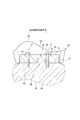
- FIG. 5 is a schematic partial cross-sectional view for explaining a fastening structure between the rotary shaft 20 and the segment 40.
- the rotating shaft 20 has a plurality of bolt holes 68 that open to the surface of the rotating shaft 20, and each segment 40 has a plurality of through holes 70 that respectively communicate with the plurality of bolt holes 68.
- Each segment 40 is fixed to the rotary shaft 20 by a plurality of bolts 72 extending through the plurality of through holes 70 and screwed into the plurality of bolt holes 68, respectively.
- the segment 40 can be reliably fixed to the rotary shaft 20 with a simple configuration.
- the through hole 70 is located in a region outside the slope portion 62.
- each segment 40 has a fastening portion 74 in which through holes 70 are formed on both sides of the slope portion 62 in the axial direction of the rotating shaft 20.
- the fastening portions 74 are provided on both sides of the slope portion 62 in the axial direction of the rotary shaft 20. For this reason, the entire divided cam surface 56 including the slope portion 62 can be further smoothed.
- the center of gravity G of the segment 40 is located in the vicinity of the key groove 66, in other words, in the vicinity of the key 64. According to this configuration, the center of gravity G of the segment 40 is located in the vicinity of the key 64, and the segment 40 is stabilized by supporting the portion of the segment 40 near the center of gravity G with the key 64.
- At least four through holes 70 are provided in the fastening portion 74 and are arranged symmetrically around the center of gravity G.
- the segment 40 is fastened to the rotating shaft 20 by at least four bolts 72 arranged symmetrically around the center of gravity G, and the segment 40 is stabilized.
- the four bolts 72 are arranged with a rotational symmetry of 180 degrees around the center of gravity G, and the center of gravity G is located at the center of the diagonal line of the four bolts 72.
- 6A and 6B are a cross-sectional view and a side view schematically showing the configuration of another segment 76, respectively.
- the segment 76 does not have the fastening portion 74, and a through hole 78 for the bolt 72 is opened in the divided cam surface 56.
- the through-hole 78 has a small diameter portion 80 and a large diameter portion 82, and a head portion 84 of the bolt 72 is accommodated in the large diameter portion 82 and abuts on a step between the small diameter portion 80 and the large diameter portion 82.
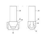
- FIG. 7 is two side views schematically showing the configuration of the piston 26 and the roller 38.
- the piston 26 includes a holding portion 86 that rotatably holds the roller 38, and a restriction portion 88 that restricts the movement of the roller 38 in the axial direction of the roller 38.
- the split cam surface 56 includes a high pressure section configured to abut against the roller 38 during a high pressure period in which the pressure in the working chamber 24 is high, and a pressure in the working chamber 24 that is lower than in the high pressure period. And the both ends of the divided cam surface 56 in the tangential direction of the rotary shaft 20 form a low pressure section.
- the cam surface 34 is formed by a plurality of divided cam surfaces 56, a discontinuous region is formed on the cam surface 34 due to a gap between the end portions of the two divided cam surfaces 56.
- the discontinuous area is inevitably rough as compared with other areas of the cam surface 34.
- both end portions of the divided cam surface 56 form a low pressure section, and the discontinuous area is located in the low pressure section. 38 can run smoothly.
- the split cam surface 56 has a length corresponding to a single reciprocation of the piston 26. According to this configuration, since the split cam surface 56 has a length corresponding to one reciprocating motion of the piston 26, the segment 40 can be reduced in size and weight.
- the segment 40 has a protrusion 90 projecting along the tangential direction of the rotary shaft 20 at one end in the tangential direction of the rotary shaft 20, and the like.
- a recess 92 that is recessed along the tangential direction is provided at the end.
- the concave part 92 of one segment 40 can receive the convex part 90 of the other segment 40 located adjacently.
- both end edges of the divided cam surface 56 are not formed in a straight line due to the presence of the convex portion 90 or the concave portion 92, and are formed by a plurality of stepped straight lines. For this reason, even if there is a gap between the end portions of the divided cam surface 56, at least a part of the roller 38 is always supported by the divided cam surface 56 in the axial direction of the roller 38. It can run smoothly.
- FIG. 8 is a flowchart schematically showing the procedure of the method for manufacturing the segment 40.
- the segment 40 is formed by sequentially subjecting the material of the segment 40 to the roughing S10, the curing process S12, and the precision machining S14.
- the roughing S10 is, for example, machining.
- the curing process S12 is, for example, a carburizing and quenching process, and may be a nitriding process, a film forming process, or the like.
- the precision processing S14 is a polishing process or the like.
- the lobe cam 36 is formed by a plurality of segments 40, and each segment 40 is formed by sequentially using the raw material of the segment 40 for the roughing S10, the hardening process S12, and the precision machining S14. Therefore, large machine tools and furnaces are not necessary.
- the mounting surface 42 is used as a reference surface for machining, so that the dimensional accuracy of the divided cam surface 56 can be easily increased.
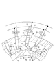
- FIG. 9 is a plan view showing an area to be subjected to the hardening process (carburizing and quenching process) S12 in the segment 40 using hatching.
- the curing process S ⁇ b> 12 is applied to the entire divided cam surface 56.
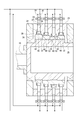
- FIG. 10 is a schematic longitudinal sectional view of a hydraulic machine.
- a plurality of cylinder portions 22 are arranged along the circumferential direction of the rotating shaft 20, and as shown in FIG. They are arranged along the axial direction of the rotary shaft 20.
- the plurality of cylinder portions 22 are arranged along the circumferential direction of the rotating shaft 20 to form an annular cylinder row, and the plurality of annular cylinder rows are arranged along the axial direction of the rotating shaft 20. It is arranged.
- a plurality of mounting surfaces 52 extend along the circumferential direction and the axial direction of the rotating shaft 20 in correspondence with the circumferential direction of the rotating shaft 20 and the plurality of cylinder portions 22 arranged along the axial direction. Are arranged.
- the plurality of mounting surfaces 52 are arranged along the circumferential direction of the rotating shaft 20 to form an annular mounting surface row, and the plurality of annular mounting surface rows are arranged in the axial direction of the rotating shaft 20. Are arranged along.
- FIG. 11 is a perspective view schematically showing the configuration of the rotating shaft 20.
- the plurality of annular mounting surface rows are offset from each other in relative rotation angles about the rotation axis 20, as shown in FIG.
- the shift of the rotation angle between the mounting surface rows corresponds to the number of mounting surfaces 52 and the number of mounting surface rows in the circumferential direction of the rotating shaft 20.
- the phases of the reciprocating motions of the plurality of pistons 26 can be made different from each other depending on the positions of the rotating shaft 20 in the circumferential direction and the axial direction. Conversion between 20 rotational movements can be performed smoothly.
- the term “along” used in the description of the above-described embodiment does not indicate only a state that is strictly parallel to a reference direction or object in a geometric sense, It also includes a state in which a certain angle (for example, an angle within 30 degrees) is formed with respect to a reference direction or object.
Landscapes
- Engineering & Computer Science (AREA)
- Mechanical Engineering (AREA)
- General Engineering & Computer Science (AREA)
- Life Sciences & Earth Sciences (AREA)
- Sustainable Development (AREA)
- Sustainable Energy (AREA)
- Chemical & Material Sciences (AREA)
- Combustion & Propulsion (AREA)
- Power Engineering (AREA)
- Wind Motors (AREA)
- Reciprocating Pumps (AREA)
- Hydraulic Motors (AREA)
Abstract
Description
この種の油圧機械は、ピストンの往復運動と回転軸の回転運動との変換を行うための変換機構を有する。例えば、特許文献1に記載された油圧機械は、変換機構として、回転軸に固定されるリングカム(ローブカム)と、リングカムのカム面とピストンの間に配置されるローラとを有する。リングカムは、回転軸の周方向に配列された複数のセグメントによって構成され、各セグメントは、ボルトによって回転軸に固定されている。各々のセグメントは、リングカムのカム面を構成する分割カム面を有し、回転軸と対向する円弧状に湾曲した取付面を有する。
再生可能エネルギから電力を生成する再生可能エネルギ発電装置において、
前記再生可能エネルギを利用して回転するように構成された主軸と、
前記主軸のトルクによって作動流体を圧縮して吐出するように構成された油圧ポンプと、
前記油圧ポンプが吐出した前記作動流体の圧力によってトルクを与えるように構成された油圧モータと、
前記油圧モータによって与えられたトルクによって発電するように構成された発電機と、を備え、
前記油圧ポンプ及び前記油圧モータのうち一方はラジアルピストン式の流体機械によって構成され、
前記流体機械は、
回転軸と、
前記回転軸の半径方向に沿って延びる少なくとも1つのシリンダ部と、
前記シリンダ部内に配置され、前記シリンダ部とともに作動室を形成するピストンと、
前記ピストンの往復運動と前記回転軸の回転運動との間の変換を行うように構成された変換機構とを有し、
前記変換機構は、
前記回転軸に対し固定され、カム面を有するローブカムと、
前記カム面と前記ピストンとの間に挟まれるローラと、を有し、
前記ローブカムは、前記回転軸の周方向に沿って配列された複数のセグメントによって構成され、
各々の前記セグメントは、前記回転軸と対向する平坦な取付面を有する。
この構成では、回転軸が平坦な搭載面を有するので、簡単な構成にて、回転軸に対し各セグメントを容易に取り付けることができる。また、取付面及び搭載面が平坦であるため、回転軸が大きな荷重を支持することができる。この結果、変換機構が、ピストンと回転軸の間で、大きなトルクを伝達することができる。
前記分割カム面は、
前記ピストンの上死点に対応する少なくとも1つの頂部と、
前記ピストンの下死点に対応する少なくとも1つの底部と、
前記頂部から前記底部に渡って延在するスロープ部と、を含む。
この構成によれば、複数のキーによって、簡単な構成にて、複数のセグメントを回転軸に係合させることができる。
一方、この構成では、取付面が平坦であり、回転軸の周りでのセグメントの回転が、取付面によって抑制される。このため、キーに作用する荷重を低減することができ、各セグメントに対し、大きな荷重を作用させることができ、流体機械の大型化を招くことなく、再生可能エネルギ発電装置の大出力化を図ることができる。
この構成によれば、セグメントの重心がキーの近傍に位置しており、セグメントの重心近傍の部分をキーで支持することにより、セグメントが安定する。
前記取付面は、前記基準面を構成している。
セグメントの分割カム面を加工によって形成する際、加工のための基準面が必要になる。この点、この構成では、平坦な取付面を基準面とすることができ、分割カム面の寸法精度を容易に高くすることができる。また、取付面を基準として、分割カム面の寸法を容易に検査することができる。
前記回転軸は、前記回転軸の表面に開口する複数のボルト孔を有し、
各々の前記セグメントは、前記複数のボルト孔にそれぞれ連通する複数の貫通孔を有し、
各々の前記セグメントは、前記複数の貫通孔内をそれぞれ延び且つ前記複数のボルト孔に螺子込まれた複数のボルトによって前記回転軸に対し固定されている。
この構成によれば、簡単な構成にて、セグメントを回転軸に確実に固定することができる。
貫通孔がスロープ部に位置している場合、貫通孔によってスロープ部に凹みが形成され、スロープ部に段差が生じてしまう。この点、この構成では、貫通孔がスロープ部の外側の領域に位置しているので、スロープ部を一層滑らかにすることができる。
この構成によれば、締結部が、回転軸の軸方向にてスロープ部の両側に設けられている。このため、スロープ部を含む分割カム面全域を一層滑らかにすることができる。
この構成によれば、セグメントの重心の周りに対称に配置された4本のボルトによって、回転軸に対しセグメントを締結することにより、セグメントが安定する。
この構成では、ピストンが規制部を有するので、回転軸に規制部を設ける必要がない。このため、セグメントの形状の自由度が高く、滑らかな分割カム面を一層容易に形成することができる。
前記分割カム面は、
前記作動室の圧力が高圧である高圧期間に前記ローラと当接するように構成された高圧区間と、
前記作動室の圧力が前記高圧期間よりも低圧である低圧期間に前記ローラと当接するように構成された低圧区間とを含み、
前記回転軸の接線方向での前記分割カム面の両端部は、前記低圧区間を形成している。
この構成によれば、分割カム面は、ピストンの1回の往復運動に対応する長さを有するので、セグメントの小型化や軽量化を図ることができる。
この構成では、ローブカムが複数のセグメントによって形成され、各セグメントが、セグメントの素材を、粗加工、硬化処理及び精密加工に順次供して形成されるので、ローブカムの製造のために、大型の工作機械や炉が必要ない。
この構成では、風力発電装置は、風を利用して、効率的に発電することができる。
再生可能エネルギ発電装置は、再生可能エネルギから電力を生成するように構成されている。再生可能エネルギ発電装置は、図1に示したように、再生可能エネルギを利用して回転するように構成された主軸10と、主軸10のトルク(トルク)によって作動流体を圧縮して吐出するように構成された油圧ポンプ12と、油圧ポンプ12が吐出した作動流体の圧力によってトルクを与えるように構成された油圧モータ14と、油圧モータ14によって与えられたトルクによって発電するように構成された発電機16と、を備える。
なお、シリンダ部22は、ハウジング23においてシリンダボアを区画する部分であり、ハウジング23は、シリンダ部22を有する一体の成形物であってもよく、或いは、独立したシリンダスリーブ(シリンダライナ)によって形成されるシリンダ部22を含む集合物であってもよい。
図3は、図2の一部を拡大して示す部分横断面図であり、ローブカム36は、回転軸20の周方向に沿って配列された複数のセグメント40によって構成されている。
各々のセグメント40は、回転軸20と対向する平坦な取付面42を有する。
風力発電装置としての再生可能エネルギ発電装置は、風を利用して効率的に発電することができる。
幾つかの実施形態では、取付面42は搭載面52に直接接触する。
幾つかの実施形態では、各々の搭載面52は、搭載面52の接線方向に沿って延びており、複数の搭載面52は、回転軸20において、正多角柱形状の軸部54の側面を形成している。
一方、この構成では、取付面42が平坦であり、回転軸20の周りでのセグメント40の回転が、取付面42によって抑制される。このため、キー64に作用する荷重を低減することができ、各セグメント40に対し、大きな荷重を作用させることができ、流体機械の大型化を招くことなく、再生可能エネルギ発電装置の大出力化を図ることができる。
この構成によれば、セグメント40の重心Gがキー64の近傍に位置しており、セグメント40の重心G近傍の部分をキー64で支持することにより、セグメント40が安定する。
幾つかの実施形態では、4本のボルト72は、重心Gを中心として180度の回転対称性をもって配列され、4本のボルト72の対角線の中央に重心Gが位置している。
粗加工S10は、例えば機械加工である。硬化処理S12は、例えば浸炭焼き入れ処理であり、窒化処理や被膜形成処理等であってもよい。精密加工S14は、研磨処理等である。
この構成によれば、複数のピストン26の往復運動の位相を、回転軸20の周方向及び軸方向での位置に応じて相互に異ならせることができ、複数のピストン26の往復運動と回転軸20の回転運動との間の変換を円滑に行うことができる。
12 油圧ポンプ
14 油圧モータ
16 発電機
20 回転軸
22 シリンダ部
23 ハウジング
24 作動室
26 ピストン
28 高圧弁
30 低圧弁
34 カム面
36 ローブカム
38 ローラ
40 セグメント
42 取付面
43 翼
44 タワー
46 ナセル
48 主軸受
50 ハブ
52 搭載面
54 軸部
56 分割カム面
58 頂部
60 底部
62 スロープ部
64 キー
66 キー溝
68 ボルト孔
70 貫通孔
72 ボルト
74 締結部
76 セグメント
78 貫通孔
80 小径部
82 大径部
84 頭部
86 保持部
88 規制部
90 凸部
92 凹部
Claims (15)
- 再生可能エネルギから電力を生成する再生可能エネルギ発電装置において、
前記再生可能エネルギを利用して回転するように構成された主軸と、
前記主軸のトルクによって作動流体を圧縮して吐出するように構成された油圧ポンプと、
前記油圧ポンプが吐出した前記作動流体の圧力によってトルクを与えるように構成された油圧モータと、
前記油圧モータによって与えられたトルクによって発電するように構成された発電機と、を備え、
前記油圧ポンプ及び前記油圧モータのうち一方はラジアルピストン式の流体機械によって構成され、
前記流体機械は、
回転軸と、
前記回転軸の半径方向に沿って延びる少なくとも1つのシリンダ部と、
前記シリンダ部内に配置され、前記シリンダ部とともに作動室を形成するピストンと、
前記ピストンの往復運動と前記回転軸の回転運動との間の変換を行うように構成された変換機構とを有し、
前記変換機構は、
前記回転軸に対し固定され、カム面を有するローブカムと、
前記カム面と前記ピストンとの間に挟まれるローラと、を有し、
前記ローブカムは、前記回転軸の周方向に沿って配列された複数のセグメントによって構成され、
各々の前記セグメントは、前記回転軸と対向する平坦な取付面を有する
ことを特徴とする再生可能エネルギ発電装置。 - 前記回転軸は、前記複数のセグメントの取付面とそれぞれ対向する複数の平坦な搭載面を有する
ことを特徴とする請求項1に記載の再生可能エネルギ発電装置。 - 各々の前記セグメントは、前記カム面の一部を構成する分割カム面を有し、
前記分割カム面は、
前記ピストンの上死点に対応する少なくとも1つの頂部と、
前記ピストンの下死点に対応する少なくとも1つの底部と、
前記頂部から前記底部に渡って延在するスロープ部と、を含む、
ことを特徴とする請求項1又は2に記載の再生可能エネルギ発電装置。 - 前記複数のセグメントを前記回転軸とそれぞれ係合させるための複数のキーを更に備えることを特徴とする請求項1乃至3の何れか一項に記載の再生可能エネルギ発電装置。
- 各々の前記キーは、各々の前記セグメントの重心の近傍に配置されていることを特徴とする請求項1乃至4の何れか一項に記載の再生可能エネルギ発電装置。
- 各々の前記セグメントは、前記分割カム面を形成するための基準として利用可能な基準面を有し、
前記取付面は、前記基準面を構成している
ことを特徴とする請求項1乃至5の何れか一項に記載の再生可能エネルギ発電装置。 - 前記回転軸は、前記回転軸の表面に開口するボルト孔を有し、
前記セグメントは、前記ボルト孔に連通する貫通孔を有し、
前記セグメントは、前記貫通孔内を延び且つ前記ボルト孔に螺子込まれたボルトによって前記回転軸に対し固定されている
ことを特徴とする請求項1乃至6の何れか一項に記載の再生可能エネルギ発電装置。 - 前記貫通孔は前記スロープ部の外側の領域に位置している
ことを特徴とする請求項7に記載の再生可能エネルギ発電装置。 - 前記セグメントは、前記回転軸の軸方向にて前記スロープ部の両側に、前記貫通孔が形成された締結部を有することを特徴とする請求項8に記載の再生可能エネルギ発電装置。
- 前記複数のボルトは、前記セグメントの重心の周りに対称に配置された4本のボルトを含むことを特徴とする請求項9に記載の再生可能エネルギ発電装置。
- 前記ピストンは、前記ローラの軸方向での前記ローラの移動を規制する規制部を有することを特徴とする請求項1乃至10の何れか一項に記載の再生可能エネルギ発電装置。
- 前記分割カム面は、
前記作動室の圧力が高圧である高圧期間に前記ローラと当接するように構成された高圧区間と、
前記作動室の圧力が前記高圧期間よりも低圧である低圧期間に前記ローラと当接するように構成された低圧区間とを含み、
前記回転軸の接線方向での前記分割カム面の両端部は、前記低圧区間を形成している
ことを特徴とする請求項1乃至11の何れか一項に記載の再生可能エネルギ発電装置。 - 前記分割カム面は、前記ピストンの1回の往復運動に対応する長さを有する
ことを特徴とする請求項1乃至12の何れか一項に記載の再生可能エネルギ発電装置。 - 前記セグメントは、前記セグメントの素材を、粗加工、硬化処理及び精密加工に順次供して形成されることを特徴とする請求項1乃至13の何れか一項に記載の再生可能エネルギ発電装置。
- 前記再生可能エネルギ発電装置は、前記再生可能エネルギとしての風を受けて前記回転軸を回転させるように構成された少なくとも1本の翼を更に備え、風力発電装置であることを特徴とする請求項1乃至14の何れか一項に記載の再生可能エネルギ発電装置。
Priority Applications (3)
| Application Number | Priority Date | Filing Date | Title |
|---|---|---|---|
| PCT/JP2013/053857 WO2014125644A1 (ja) | 2013-02-18 | 2013-02-18 | 再生可能エネルギ発電装置 |
| EP13843057.4A EP2821638B1 (en) | 2013-02-18 | 2013-02-18 | Renewable energy generator |
| JP2014504888A JP5627818B1 (ja) | 2013-02-18 | 2013-02-18 | 再生可能エネルギ発電装置 |
Applications Claiming Priority (1)
| Application Number | Priority Date | Filing Date | Title |
|---|---|---|---|
| PCT/JP2013/053857 WO2014125644A1 (ja) | 2013-02-18 | 2013-02-18 | 再生可能エネルギ発電装置 |
Publications (1)
| Publication Number | Publication Date |
|---|---|
| WO2014125644A1 true WO2014125644A1 (ja) | 2014-08-21 |
Family
ID=51353669
Family Applications (1)
| Application Number | Title | Priority Date | Filing Date |
|---|---|---|---|
| PCT/JP2013/053857 Ceased WO2014125644A1 (ja) | 2013-02-18 | 2013-02-18 | 再生可能エネルギ発電装置 |
Country Status (3)
| Country | Link |
|---|---|
| EP (1) | EP2821638B1 (ja) |
| JP (1) | JP5627818B1 (ja) |
| WO (1) | WO2014125644A1 (ja) |
Cited By (3)
| Publication number | Priority date | Publication date | Assignee | Title |
|---|---|---|---|---|
| CN106050594A (zh) * | 2016-08-01 | 2016-10-26 | 浙江水魔力机电设备有限公司 | 一种清洗机上的无油泵 |
| CN106089618A (zh) * | 2016-08-01 | 2016-11-09 | 浙江水魔力机电设备有限公司 | 一种柱塞以离心方式运动的泵体 |
| JP2021532308A (ja) * | 2018-08-06 | 2021-11-25 | 青島極致創新科技有限公司Qingdao Acme Innovation Technology Co., Ltd. | プランジャーポンプ及びプランジャーモータ |
Families Citing this family (2)
| Publication number | Priority date | Publication date | Assignee | Title |
|---|---|---|---|---|
| JP5726370B2 (ja) | 2013-03-06 | 2015-05-27 | 三菱重工業株式会社 | 油圧機械及び再生エネルギー発電装置 |
| DE102016124048A1 (de) * | 2016-12-12 | 2018-06-14 | Kamat Gmbh & Co. Kg | Axialkolbenpumpe mit großer Fördermenge bei geringer Drehzahl und Verwendung einer Kolbenpumpe in einer Windkraftanlage |
Citations (5)
| Publication number | Priority date | Publication date | Assignee | Title |
|---|---|---|---|---|
| GB248490A (en) | 1924-12-10 | 1926-03-10 | James Henry Routledge | Improvements in the seating arrangements of motor char-a-bancs |
| JPH08508557A (ja) * | 1993-03-30 | 1996-09-10 | ウルフ ヘンリクソン, | 液圧駆動システム |
| JP2006112460A (ja) * | 2004-10-12 | 2006-04-27 | Toyota Motor Corp | 動力伝達装置およびラジアルピストンポンプ |
| JP2012526947A (ja) * | 2010-08-17 | 2012-11-01 | アルテミス インテリジェント パワー リミティド | リングカムおよびリングカムを含む流体作動機械 |
| JP2013501868A (ja) * | 2010-11-30 | 2013-01-17 | 三菱重工業株式会社 | 風力発電装置及び潮流発電装置並びにその運転制御方法 |
Family Cites Families (2)
| Publication number | Priority date | Publication date | Assignee | Title |
|---|---|---|---|---|
| US20100032959A1 (en) * | 2008-08-08 | 2010-02-11 | General Electric Company | Wind turbine system |
| JP5615349B2 (ja) * | 2011-04-05 | 2014-10-29 | 三菱重工業株式会社 | 再生エネルギー型発電装置及び油圧ポンプの取付け方法 |
-
2013
- 2013-02-18 EP EP13843057.4A patent/EP2821638B1/en not_active Not-in-force
- 2013-02-18 WO PCT/JP2013/053857 patent/WO2014125644A1/ja not_active Ceased
- 2013-02-18 JP JP2014504888A patent/JP5627818B1/ja not_active Expired - Fee Related
Patent Citations (5)
| Publication number | Priority date | Publication date | Assignee | Title |
|---|---|---|---|---|
| GB248490A (en) | 1924-12-10 | 1926-03-10 | James Henry Routledge | Improvements in the seating arrangements of motor char-a-bancs |
| JPH08508557A (ja) * | 1993-03-30 | 1996-09-10 | ウルフ ヘンリクソン, | 液圧駆動システム |
| JP2006112460A (ja) * | 2004-10-12 | 2006-04-27 | Toyota Motor Corp | 動力伝達装置およびラジアルピストンポンプ |
| JP2012526947A (ja) * | 2010-08-17 | 2012-11-01 | アルテミス インテリジェント パワー リミティド | リングカムおよびリングカムを含む流体作動機械 |
| JP2013501868A (ja) * | 2010-11-30 | 2013-01-17 | 三菱重工業株式会社 | 風力発電装置及び潮流発電装置並びにその運転制御方法 |
Non-Patent Citations (1)
| Title |
|---|
| See also references of EP2821638A4 |
Cited By (4)
| Publication number | Priority date | Publication date | Assignee | Title |
|---|---|---|---|---|
| CN106050594A (zh) * | 2016-08-01 | 2016-10-26 | 浙江水魔力机电设备有限公司 | 一种清洗机上的无油泵 |
| CN106089618A (zh) * | 2016-08-01 | 2016-11-09 | 浙江水魔力机电设备有限公司 | 一种柱塞以离心方式运动的泵体 |
| JP2021532308A (ja) * | 2018-08-06 | 2021-11-25 | 青島極致創新科技有限公司Qingdao Acme Innovation Technology Co., Ltd. | プランジャーポンプ及びプランジャーモータ |
| JP7076870B2 (ja) | 2018-08-06 | 2022-05-30 | 青島極致創新科技有限公司 | プランジャーポンプ及びプランジャーモータ |
Also Published As
| Publication number | Publication date |
|---|---|
| JPWO2014125644A1 (ja) | 2017-02-02 |
| JP5627818B1 (ja) | 2014-11-19 |
| EP2821638A1 (en) | 2015-01-07 |
| EP2821638A4 (en) | 2015-11-11 |
| EP2821638B1 (en) | 2016-09-07 |
Similar Documents
| Publication | Publication Date | Title |
|---|---|---|
| JP5627818B1 (ja) | 再生可能エネルギ発電装置 | |
| US9127656B2 (en) | Ring cam and fluid-working machine including ring cam | |
| US20120260765A1 (en) | Ring cam and fluid-working machine including ring cam | |
| EP2440777B1 (en) | Ring cam and fluid-working machine including ring cam | |
| JP5614093B2 (ja) | フレッティングコロージョン対応揺動ベーン型ポンプ・アクチュエータ | |
| WO2013080399A2 (en) | Power generating apparatus of renewable energy and method of attaching a hydraulic pump thereof | |
| JP5832668B2 (ja) | 風力発電装置 | |
| EP3318753B1 (en) | Renewable-energy type power generating apparatus and method of assembling the same | |
| EP2955374B1 (en) | Radial-piston hydraulic machine and wind turbine power generating apparatus | |
| JP2014129771A (ja) | ラジアルピストン式油圧機械および風力発電装置 | |
| EP2821648A1 (en) | Hydraulic machine and regenerative energy power generation device | |
| JP5738476B2 (ja) | 流体作動装置及び風力発電装置 | |
| JP6475538B2 (ja) | 油圧機械及び再生エネルギー型発電装置 | |
| JP6193883B2 (ja) | 再生エネルギー型発電装置 | |
| WO2014097427A1 (ja) | 再生可能エネルギー型発電装置 | |
| EP2786018A2 (en) | Power generating apparatus of renewable energy and method of attaching a hydraulic pump thereof | |
| JP2014129770A (ja) | ラジアルピストン式油圧機械、その組立て方法及び風力発電装置 | |
| EP3211228A1 (en) | Hydraulic machine and wind turbine power generating apparatus | |
| EP3171062B1 (en) | Valve block, fluid machine, and renewable-energy power generating apparatus | |
| JP6444905B2 (ja) | 油圧機械、リングカム及び再生可能エネルギー型発電装置 | |
| JP2014129772A (ja) | ラジアルピストン式油圧機械および風力発電装置 | |
| CN102678182A (zh) | 带有双太阳轮的星旋式转动装置、发动机及流体机械 |
Legal Events
| Date | Code | Title | Description |
|---|---|---|---|
| ENP | Entry into the national phase |
Ref document number: 2014504888 Country of ref document: JP Kind code of ref document: A |
|
| REEP | Request for entry into the european phase |
Ref document number: 2013843057 Country of ref document: EP |
|
| WWE | Wipo information: entry into national phase |
Ref document number: 2013843057 Country of ref document: EP |
|
| 121 | Ep: the epo has been informed by wipo that ep was designated in this application |
Ref document number: 13843057 Country of ref document: EP Kind code of ref document: A1 |
|
| NENP | Non-entry into the national phase |
Ref country code: DE |