WO2014125833A1 - 低周波印加装置 - Google Patents
低周波印加装置 Download PDFInfo
- Publication number
- WO2014125833A1 WO2014125833A1 PCT/JP2014/000770 JP2014000770W WO2014125833A1 WO 2014125833 A1 WO2014125833 A1 WO 2014125833A1 JP 2014000770 W JP2014000770 W JP 2014000770W WO 2014125833 A1 WO2014125833 A1 WO 2014125833A1
- Authority
- WO
- WIPO (PCT)
- Prior art keywords
- audio signal
- low
- signal
- low frequency
- frequency
- Prior art date
- Legal status (The legal status is an assumption and is not a legal conclusion. Google has not performed a legal analysis and makes no representation as to the accuracy of the status listed.)
- Ceased
Links
Images




Classifications
-
- A—HUMAN NECESSITIES
- A61—MEDICAL OR VETERINARY SCIENCE; HYGIENE
- A61N—ELECTROTHERAPY; MAGNETOTHERAPY; RADIATION THERAPY; ULTRASOUND THERAPY
- A61N1/00—Electrotherapy; Circuits therefor
- A61N1/18—Applying electric currents by contact electrodes
- A61N1/32—Applying electric currents by contact electrodes alternating or intermittent currents
- A61N1/36—Applying electric currents by contact electrodes alternating or intermittent currents for stimulation
- A61N1/36014—External stimulators, e.g. with patch electrodes
- A61N1/3603—Control systems
- A61N1/36034—Control systems specified by the stimulation parameters
-
- G—PHYSICS
- G10—MUSICAL INSTRUMENTS; ACOUSTICS
- G10L—SPEECH ANALYSIS TECHNIQUES OR SPEECH SYNTHESIS; SPEECH RECOGNITION; SPEECH OR VOICE PROCESSING TECHNIQUES; SPEECH OR AUDIO CODING OR DECODING
- G10L21/00—Speech or voice signal processing techniques to produce another audible or non-audible signal, e.g. visual or tactile, in order to modify its quality or its intelligibility
- G10L21/06—Transformation of speech into a non-audible representation, e.g. speech visualisation or speech processing for tactile aids
- G10L21/16—Transforming into a non-visible representation
-
- G—PHYSICS
- G10—MUSICAL INSTRUMENTS; ACOUSTICS
- G10L—SPEECH ANALYSIS TECHNIQUES OR SPEECH SYNTHESIS; SPEECH RECOGNITION; SPEECH OR VOICE PROCESSING TECHNIQUES; SPEECH OR AUDIO CODING OR DECODING
- G10L25/00—Speech or voice analysis techniques not restricted to a single one of groups G10L15/00 - G10L21/00
- G10L25/03—Speech or voice analysis techniques not restricted to a single one of groups G10L15/00 - G10L21/00 characterised by the type of extracted parameters
- G10L25/18—Speech or voice analysis techniques not restricted to a single one of groups G10L15/00 - G10L21/00 characterised by the type of extracted parameters the extracted parameters being spectral information of each sub-band
-
- G—PHYSICS
- G10—MUSICAL INSTRUMENTS; ACOUSTICS
- G10L—SPEECH ANALYSIS TECHNIQUES OR SPEECH SYNTHESIS; SPEECH RECOGNITION; SPEECH OR VOICE PROCESSING TECHNIQUES; SPEECH OR AUDIO CODING OR DECODING
- G10L25/00—Speech or voice analysis techniques not restricted to a single one of groups G10L15/00 - G10L21/00
- G10L25/48—Speech or voice analysis techniques not restricted to a single one of groups G10L15/00 - G10L21/00 specially adapted for particular use
Definitions
- the present invention relates to a low-frequency application device.
- EMS Electro Muscle Stimulation
- various methods for supplying current have been proposed. As one of them, a method has been proposed in which the intensity of sound is extracted from an input audio signal, a voltage having a strength corresponding to music emitted from a speaker is supplied to the human body, and a current is passed through the muscle. (For example, refer to Patent Document 1).
- the present invention has been made in view of the circumstances described above, and can apply a low-frequency voltage in synchronization with music to be emitted, and prevent unexpectedly large voltage from being suddenly supplied to the human body. It is an object of the present invention to provide a low-frequency application device that can be used.
- the low-frequency application device includes an audio signal supply unit that outputs an audio signal, a filter unit that passes an audio signal in a predetermined frequency band among the audio signals, and an audio signal that passes through the filter unit in advance.
- an audio signal supply unit that outputs an audio signal
- a filter unit that passes an audio signal in a predetermined frequency band among the audio signals
- an audio signal that passes through the filter unit in advance By receiving a sound signal of a set level or higher, a signal generator that generates a pulse signal, an electrode for supplying current to the human body, and the generated pulsed low-frequency voltage are applied.
- a control means for controlling the output of the low frequency voltage by the pulse signal.
- the low-frequency application device of the embodiment can also include a speaker that emits sound.
- the low frequency applying device of the present invention may further comprise a comparing means for comparing the level of the audio signal that has passed through the filter means with a threshold value.
- pulse width varying means for varying the pulse width of the low frequency voltage corresponding to the threshold value can be further provided.
- the filter means has a first filter means for passing the low frequency band of the audio signal for the right channel and a second filter means for passing the low frequency band of the audio signal for the left channel. It is desirable to provide.
- the low-frequency application device of the embodiment can further include a pass frequency varying unit that varies the frequency that the filter unit passes.
- the low-frequency application device includes first to third electrodes and first to third signal generation means, and the first to third pulse signals output from the first to third signal generation means are output to the first to third signals. It is desirable to further include output electrode switching means for variably supplying each of the electrodes. It is desirable that the first electrode corresponds to an audio signal for the right channel, and the second electrode corresponds to an audio signal for the left channel.
- the low-frequency application device displays at least one of an output mode of a low-frequency signal, presence / absence of output of an audio signal, information indicating the quality of audio emitted from a speaker, and information corresponding to a change in the audio signal Means may further be provided.
- the low frequency application device of the present invention it is possible to apply a low frequency voltage to the human body in synchronization with the music to be emitted, and to prevent an unexpectedly large voltage from being suddenly supplied to the human body. It becomes possible.
- FIG. 9 is a waveform diagram illustrating a first A / D conversion unit 232A according to the second embodiment. The figure which shows the period of the low frequency voltage which the pulse width setting part 280 of Embodiment 2 determines.
- FIG. 1 is a block diagram illustrating an internal configuration of the low-frequency application device 1 according to the first embodiment.
- the low-frequency application device 1 includes a sound source input unit 110, an audio output unit 120, a trigger signal generation unit 130, an EMS output unit 140, a display unit 150, a button 160, and a control unit 170.
- the low frequency application device 1 includes a DC power source such as a secondary battery for supplying power to each unit such as the control unit 170 and a rectifier circuit for AC-DC conversion of a commercial power source obtained from a general household outlet. May be built in.
- the low frequency application device 1 boosts the output voltage of the built-in DC power supply to about 100V at the maximum.
- the low frequency applying device 1 applies a low to medium frequency voltage of about 10 kHz or less (hereinafter referred to as “low frequency voltage”) to the skin surface of the patient via the detachable electrode pads 3 and 4. Can do.
- the low frequency application device 1 can synchronize ON / OFF of the low frequency voltage to be applied to music output from the speaker 121 or the earphone 122.
- the flow of lymph in the subject can be promoted.
- treatment effects such as fatigue recovery can be obtained.
- the low frequency applying device 1 has waterproofness and can be used even in a bathroom.
- the sound source input unit 110 includes a wireless reception unit 111, a built-in storage 112, an external media interface 113, and a sound source processing unit 114.
- the wireless reception unit 111 wirelessly communicates from the external device 2 via the antenna 111A with various types of music files such as AAC (Advanced Audio Coding) format and MP3 (MPEG Audio Layer-3) format, and such music files.
- the audio signal after decoding is received.
- the “voice signal” includes a signal including only a human voice, a signal including both a human voice and music, and a signal including only music (so-called instrumental).
- the wireless reception unit 111 corresponds to wireless communication of various standards such as Bluetooth (registered trademark), Wi-Fi (registered trademark), wireless LAN, and infrared.
- the wireless receiving unit 111 can also receive a radio audio signal sent from a broadcasting station.
- the built-in storage 112 is a flash memory that can hold music files. Music files and audio signals are input to the external media interface 113 from other than the external device 2.
- the external media interface 113 is provided with a wired LAN port, a line input terminal, a USB (Universal Serial Bus) terminal, an SD card insertion slot, etc. (not shown).
- the external media interface 113 may be equipped with a microphone for collecting sounds around the low frequency applying device 1.
- the sound source processing unit 114 is an audio signal supply unit that outputs an audio signal to the audio output unit 120 or the trigger signal generation unit 130.
- the sound source processing unit 114 has a function for selecting an output source of a music file or an audio signal, an audio signal bypass function, an audio signal decoding or music file encoding function, and an audio signal right channel left channel separation function.
- the sound source processing unit 114 selects and determines an output source of a music file or an audio signal from the wireless reception unit 111, the internal storage 112, and the external media interface 113. For example, the sound source processing unit 114 reads and decodes an MP3 format music file from the built-in storage 112, and outputs an audio signal to the audio output unit 120 and the trigger signal generation unit 130.
- the sound source processing unit 114 When the decoded audio signal transmitted from the external device 2 is input from the wireless reception unit 111, the sound source processing unit 114 directly encodes the audio output unit 120 and the trigger signal without encoding the decoded audio signal.
- the data is output to the generation unit 130.
- the audio signal may be a stereo signal.
- the sound source processing unit 114 can output the stereo signal as it is to the audio output unit 120 and the trigger signal generation unit 130.
- the sound source processing unit 114 may also separate the right channel audio signal and the left channel audio signal included in the stereo signal and output them separately to the audio output unit 120 and the trigger signal generation unit 130, respectively. it can.
- the audio signal may be a monaural signal. In this case, the sound source processing unit 114 outputs the audio signal as a monaural signal to the audio output unit 120 and the trigger signal generation unit 130.
- the audio output unit 120 is a connection unit for detachably connecting the speaker 121 and the earphone 122 to the low frequency applying device 1.
- the speaker 121 may be built in the low frequency applying device 1 without being detachably connected.
- the audio output unit 120 includes an amplifier circuit (not shown), amplifies the audio signal output from the sound source processing unit 114, and outputs the amplified audio signal to the speaker 121 and the earphone 122.
- the trigger signal generation unit 130 generates a pulse-like trigger signal for synchronizing the timing of the sound emitted from the speaker 121 or the earphone 122 and the application of the pulse voltage to the patient.
- the trigger signal generation unit 130 includes first to third filter circuits 131A to 131C and first to third A / D conversion units 132A to 132C. (Regarding the first to third filter circuits 131A to 131C)
- the first to third filter circuits 131A to 131C are band-pass filters realized using, for example, an operational amplifier.
- the first to third filter circuits 131A to 131C pass an audio signal in a predetermined frequency band (for example, a band including a low frequency range or a main melody) among the audio signals output from the sound source processing unit 114. In the case where a band containing the main melody of the music signal is passed, it is desirable to set the cut-off frequency so that the pass band is approximately 100 Hz to 2 kHz.
- the first to third filter circuits 131A to 131C may be low-pass filters.
- the first to third filter circuits 131A to 131C can be configured using a fifth-order Butterworth filter or a Salenkey filter.
- the first to third filter circuits 131A to 131C desirably have a gain of ⁇ 3 dB near 150 Hz and a gain of ⁇ 60 dB near 200 Hz. It is desirable that the first to third filter circuits 131A to 131C allow a ripple and have a steep cutoff characteristic.
- an audio signal of the right channel among audio signals is input from the sound source processing unit 114 to the first filter circuit 131A.
- the first filter circuit 131A passes a low-frequency audio signal for the right channel.
- the audio signal of the left channel among the audio signals is input from the sound source processing unit 114 to the second filter circuit 131B.
- the second filter circuit 131B passes the low-frequency audio signal for the left channel.
- the audio signal is input from the sound source processing unit 114 to the third filter circuit 131C as a stereo signal. It is assumed that the third filter circuit 131C passes a mid to high frequency audio signal corresponding to the main melody.
- the first to third filter circuits 131A to 131C can appropriately change the passing frequency band within a range of 50 Hz to 2 kHz.
- the first to third A / D converters 132A to 132C are signal generation means for generating a trigger signal based on an audio signal having a preset level or higher among audio signals that have passed through the first to third filter circuits 131A to 131C. It is.
- the first to third A / D converters 132A to 132C hold a threshold necessary for generating a trigger signal in a memory (not shown).
- the threshold value can be appropriately changed depending on the music genre to which the music signal corresponds. For example, the threshold value can be changed by operating the button 160 by the practitioner.
- the “music genre” is, for example, ROCK, POPS, JAZZ, or CLASSIC.
- the audio signal that has passed through the first filter circuit 131A is input to the first A / D converter 132A.
- audio signals that have passed through the second and third filter circuits 131B and 131C are input to the second and third A / D converters 132B and 132C, respectively.
- the first to third A / D converters 132A to 132C generate a pulse-shaped trigger signal having a predetermined width based on the input audio signal.
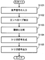
- FIG. 2 is a flowchart showing the operation of the first A / D converter 132A.
- FIG. 3 is a waveform diagram showing the audio signal after passing through the first filter circuit 131A.
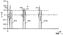
- FIG. 4 is a waveform diagram showing the trigger signal.
- FIG. 5 is a diagram showing trigger signals output from the first to third A / D converters 132A to 132C.
- the second and third A / D conversion units 132B and 132C have the same configuration and function as the first A / D conversion unit 132A, and thus the detailed description of the second and third A / D conversion units 132B and 132C. Is omitted.
- (1) Input of audio signal (step S101)
- the audio signal that has passed through the first filter circuit 131A is input to the first A / D converter 132A (see FIG. 3).
- the first filter circuit 131A is configured to pass only an audio signal of 50 Hz or less. Therefore, an audio signal corresponding to the sound of a low-frequency instrument (for example, bass or bass drum) among the audio signals output from the sound source processor 114 is input to the first A / D converter 132A.
- the first A / D converter 132A performs envelope detection (envelope detection) on the input audio signal.
- envelope detection envelope detection
- a waveform with a small amplitude level (for example, see the symbol P1 in FIG. 3) of the audio signal is smoothed, and only an audio signal with a certain level or more (for example, see the symbols P2 to P4 in FIG. 3) is detected. It becomes like this.
- the first A / D converter 132A can detect a component from DC to 2 kHz included in the audio signal.
- the first A / D conversion unit 132A compares the level of the detected audio signal with the held threshold value, and extracts an audio signal having the same level as the threshold value (see the broken line in FIG. 3) (step S103).
- the threshold value is, for example, a value that allows extraction of an audio signal of ⁇ 20 dB or more out of the level of the entire audio signal.
- the first A / D converter 132A has a trigger signal (see symbols P8 to P10 in FIG. 4) that rises at the intersection of the audio signal and the threshold (see symbols P5 to P7 in FIGS. 3 and 4). Is generated (step S104).
- the trigger signal has a pulse width determined by a flip-flop circuit. The trigger signal generated in this way corresponds to the output timing of sound that is easily perceived by the patient as sound or vibration among sounds output from the speaker 121 and the earphone 122. Note that there are cases where audio signals equal to or greater than the threshold value continue in a short time (see symbols P6 and P11 in FIG. 4).
- the first A / D conversion unit 132A outputs the trigger signal generated as described above to the EMS output unit 140.
- the second and third A / D converters 132B and 132C similarly generate a trigger signal and output it to the EMS output unit 140.
- trigger signals as shown in FIG. 5 are output from the first to third A / D conversion units 132A to 132C to the EMS output unit 140.
- the EMS output unit 140 will be described with reference to FIG. 1 again.
- the EMS output unit 140 includes an electrode selector 141, first to third EMS oscillation units 142A to 142C, and first to third electrode units 143A to 143C.
- the electrode selector 141 is an output electrode switching unit that variably supplies a trigger signal input from the first to third A / D conversion units 132A to 132C to the first to third EMS oscillation units 142A to 142C.
- the electrode selector 141 can output the trigger signal input from the first A / D conversion unit 132A to the third EMS oscillation unit 142C.
- the electrode selector 141 can output the trigger signal input from the third A / D conversion unit 132C to the second EMS oscillation unit 142B.
- the first to third EMS oscillators 142A to 142C can generate a pulsed low frequency voltage.
- the first to third EMS oscillation units 142A to 142C apply pulsed low frequency voltages to the first to third electrode units 143A to 143C, and supply corresponding currents to the patient via the electrode pads 3 and 4.
- the first to third EMS oscillation units 142A to 142C apply a low frequency voltage to the first to third electrode units 143A to 143C in synchronization with the input trigger signal.
- a low frequency voltage is applied to the first to third electrode units 143A to 143C so as to be synchronized with the audio signal output from the sound source processing unit 114 to the audio output unit 120.
- the first to third EMS oscillating units 142A to 142C desirably have good responsiveness to the trigger signal, and it is desirable to employ a transformer type circuit as an output circuit for outputting a low frequency voltage.
- the first to third electrode portions 143A to 143C are electrode portions that apply the generated pulsed low-frequency voltage to the human body and supply a corresponding current to the skin.
- a pair of positive and negative electrode pads 3 and 4 are connected to the first to third electrode portions 143A to 143C, respectively.
- the electrode pads 3 and 4 are affixed to the skin surface of the person to be treated.
- the low frequency voltage by the first to third electrode portions 143A to 143C is applied to the skin of the patient, and a low frequency current flows through the muscle of the patient.
- This low-frequency current is transmitted to the body of the subject and the body specific part, so that the subject can experience EMS synchronized with the music output from the speaker 121 and the earphone 122.
- the display unit 150 includes an LED (Light Emitting Diode) 151 and an LCD (Liquid Crystal Display) 152.
- the LED 151 and the LCD 152 include the presence / absence and mode of low-frequency voltage generated by the first to third EMS oscillation units 142A to 142C (frequency and intensity of the low-frequency voltage to be generated), the sound source processing unit 114 to the audio output unit 120 or trigger It is a notification means for informing at least one of the information indicating the presence / absence of the output of the audio signal to the signal generation unit 130 and the quality and volume of the sound emitted from the speaker 121 or the earphone 122.
- the LED 151 when an audio signal is output from the sound source processing unit 114 to the audio output unit 120 or the trigger signal generation unit 130, the LED 151 is lit.
- the LED 151 can be blinked so as to be synchronized with the audio signal output to the audio output unit 120 or the trigger signal generation unit 130. In this case, the LED 151 blinks so as to synchronize with the music output from the speaker 121 or the earphone 122.
- the trigger signal generated by the first to third A / D conversion units 132A to 132C may be output to the signal control unit 175.
- a graphic (such as a bar-shaped indicator or a screen saver that moves up and down in accordance with the timing of the sound) can be displayed on the LCD 152 so as to be synchronized with the audio signal output to the audio output unit 120 or the trigger signal generation unit 130.
- the graphic is displayed on the LCD 152 so as to be synchronized with the music output from the speaker 121 or the earphone 122.
- the display unit 150 may be configured to include only one of the LED 151 and the LCD 152.
- the button 160 is a physical switch that receives an operation by the practitioner.
- An example of “operation” is to select from which of the wireless reception unit 111, the internal storage 112, or the external media interface 113 an audio signal is obtained.
- Another example of the “operation” is a change of the frequency band that the first to third filter circuits 131A to 131C pass.
- the “operation” includes an operation for changing the threshold value held by the first to third A / D conversion units 132A to 132C, the strength of the low frequency voltage applied by the first to third EMS oscillation units 142A to 142C, and the frequency The application pattern is changed.
- the image corresponding to the button 160 may be displayed on the LCD 152 so that the physical button 160 is not provided.
- the control unit 170 includes a memory 171, a threshold setting unit 172, a filter setting unit 173, an EMS control unit 174, and a signal control unit 175 for controlling them.
- the memory 171 has a plurality of pieces of pass frequency band information indicating frequency bands that the first to third filter circuits 131A to 131C pass, and a plurality of threshold values held in the first to third A / D conversion units 132A to 132C. Stored in advance.
- the memory 171 stores in advance a plurality of pieces of low frequency level information indicating the strength of the low frequency voltage generated by the first to third EMS oscillators 142A to 142C.
- Information indicating the lighting pattern of the LED 151 and information to be displayed on the LCD 152 are stored in the memory 171 in advance.
- the memory 171 stores in advance information indicating a plurality of waveform patterns of low frequency voltages. “Several waveform patterns” can give different stimuli to the patient (for example, “tick” stimulus such as tapping or “jiwaji” stimulus that is pressed by a person ’s finger). it can.
- the threshold setting unit 172 is a threshold variable unit that varies the threshold held by the first to third A / D conversion units 132A to 132C.
- the threshold value setting unit 172 reads the threshold value from the memory 171 and outputs it to the first to third A / D conversion units 132A to 132C to overwrite the threshold value held by the first to third A / D conversion units 132A to 132C.
- the filter setting unit 173 is a pass frequency varying unit that varies the pass frequency of the audio signal of the first to third filter circuits 131A to 131C.
- the filter setting unit 173 reads the pass frequency band information from the memory 171 and outputs filter variable signals corresponding to the pass frequency band information to the first to third filter circuits 131A to 131C. As a result, the frequency band that the first to third filter circuits 131A to 131C pass is changed.
- the EMS control unit 174 supplies power to the first to third EMS oscillation units 142A to 142C. At this time, the EMS control unit 174 reads the low frequency level information from the memory 171. Then, the EMS control unit 174 supplies power corresponding to the low frequency level information to the first to third EMS oscillation units 142A to 142C. Thus, the strength of the low frequency voltage applied to the first to third electrode portions 143A to 143C can be easily changed.
- the EMS control unit 174 can output information indicating the waveform pattern of the low frequency voltage applied to the first to third electrode units 143A to 143C to the first to third EMS oscillation units 142A to 142C. As a result, various patterns of EMS can be given to the patient.
- the signal control unit 175 can detect the operation of the button 160 by the practitioner.
- the signal control unit 175 controls the threshold setting unit 172, the filter setting unit 173, the EMS control unit 174, or the sound source processing unit 114 in accordance with the detected operation.
- the signal control unit 175 controls the sound source processing unit 114 to select and determine which of the wireless reception unit 111, the internal storage 112, and the external media interface 113 is the audio signal output source.
- the electrode pads 3 and 4 connected to the first to third electrode portions 143A to 143C are attached to the body or body specific part of the patient.
- a low frequency voltage synchronized with the audio signal output from the sound source processing unit 114 can be applied to the skin of the patient.
- the electrode pads 3 and 4 connected to the first electrode portion 143A and the second electrode portion 143B to which a low-frequency voltage synchronized with a low-frequency sound is applied are connected to a body part (abdominal muscle, thigh muscle or back muscle) having a large amount of muscle mass. ) Makes it easier for the patient to feel like they are listening to music at the live venue. For example, by stretching the electrode pads 3 and 4 connected to the third electrode portion 143C on the shoulder of the subject, the subject can feel low-frequency stimulation synchronized with the sound of the main melody on the shoulder.
- the low frequency application device 1 only the pulse signal corresponding to the rhythm of music is generated from the audio signal output from the sound source processing unit 114, and the strength of the low frequency voltage is controlled by the EMS control unit 174. To do. This can prevent unexpectedly large current from being supplied suddenly.
- a low-frequency voltage can be applied to the user's skin in synchronization with the music signal output from the sound source processing unit 114, and an unexpectedly large voltage is suddenly supplied. It can be prevented from being supplied to the human body.
- FIG. 6 is a block diagram illustrating an internal configuration of the low-frequency application device 21 according to the second embodiment.
- FIG. 7 is a waveform diagram for explaining the operation of the first A / D converter 232A of the second embodiment.
- FIG. 8 is a diagram illustrating the period of the low frequency voltage determined by the pulse width setting unit 280 of the second embodiment.
- the same components as those of the low-frequency application device 1 of Embodiment 1 shown in FIGS. 1 to 5 are given the same reference numerals, and the description thereof is omitted. As illustrated in FIG.
- the low-frequency application device 21 replaces the trigger signal generation unit 130 and the EMS output unit 140 included in the low-frequency application device 1 according to the first embodiment with a trigger signal generation unit 230 and an EMS.
- An output unit 240 is provided.
- the low frequency applying device 21 includes a pulse width setting unit 280.
- the trigger signal generation unit 230 includes first to third A / D conversion units 232A to 232C corresponding to the first to third A / D conversion units 132A to 132C included in the low frequency applying device 1 of the first embodiment.
- the first to third A / D converters 232A to 232C can omit the envelope processing in order to shorten the signal processing time. (About the first A / D converter 232A)
- the first A / D conversion unit 232A will be described. Since the second and third A / D converters 232B and 232C have the same configuration and function as the first A / D converter 232A, detailed descriptions of the second and third A / D converters 232B and 232C are omitted. To do.
- the first A / D converter 132A holds a plurality of threshold values S1 to S3, and compares the input audio signal with the threshold values S1 to S3 simultaneously.
- the first A / D conversion unit 132A generates a trigger signal when detecting an audio signal having the threshold value S1 or more.
- the first A / D conversion unit 132A outputs to the electrode selector 141.
- the first A / D conversion unit 232A outputs detection threshold information indicating which threshold value among the threshold values S1 to S3 is detected to the pulse width setting unit 280.
- the EMS output unit 240 includes first to third EMS oscillators 242A to 242C corresponding to the first to third EMS oscillators 142A to 142C included in the low frequency applying device 1 of the first embodiment. .
- the first to third EMS oscillating units 242A to 242C receive a trigger signal from the electrode selector 141, respectively.
- the EMS output unit 240 receives the application time information indicating the application time per cycle of the low frequency voltage from the pulse width setting unit 280.
- the first to third EMS oscillation units 242A to 242C are supplied with electric power from the EMS control unit 174 and apply a low frequency voltage having a period corresponding to the received application time information to the first to third electrode units 143A to 143C. .
- the pulse width setting unit 280 is a pulse width varying unit that varies the pulse width of the low frequency voltage applied by the first to third EMS oscillation units 242A to 242C. As shown in FIG. 8, the pulse width setting unit 280 determines the pulse width of the low frequency voltage in accordance with the detection threshold information output from the first to third A / D conversion units 232A to 232C. This pulse width is determined by the application time for one cycle of the low-frequency voltage. Specifically, the pulse width setting unit 280, when the detection threshold information received from the first to third A / D conversion units 232A to 232C indicates the threshold S1, applies the low frequency voltage application time T1. , T2 is set to 20 ⁇ s, respectively, and it is determined to apply a low-frequency voltage having a period of 40 ⁇ s.
- the pulse width setting unit 280 sets the low frequency voltage application times T3 and T4 to 40 ⁇ m, respectively. It is determined that a low frequency voltage having a period of 80 ⁇ sec is applied.
- the pulse width setting unit 280 sets the low frequency voltage application times T5 and T6 to 80 ⁇ m, respectively. It is determined that a low frequency voltage having a period of 160 ⁇ sec is applied.
- the pulse width setting unit 280 outputs the application time of one cycle of the determined low frequency voltage to the first to third EMS oscillation units as application time information.
- the pulse width setting unit 280, the first to third A / D conversion units 232A to 232C, and the first to third EMS oscillation units 242A to 242C operate in synchronization with each other by a synchronization clock (not shown).
- the first A / D conversion unit 132A holds a plurality of threshold values S1 to S3 and simultaneously compares the input audio signal with the threshold values S1 to S3.
- the pulse signal is periodically output in a short period.
- the period during which the low frequency voltage is not output can be reduced. If the period during which the low frequency voltage is not output becomes long, the patient may be bored. According to the low-frequency application device 21, this can be prevented.
- the pulse width setting unit 280 can vary the application time per cycle of the low frequency voltage based on the detection threshold information. For example, when detection threshold value information corresponding to the threshold value S3 for detecting a high level audio signal is output, the pulse width setting unit 280 sets one cycle of the low frequency voltage in a short time.
- the pulse width setting unit 280 sets one cycle of the low frequency voltage in a short time.
- the pulse width of the low frequency voltage is narrowed. Therefore, a fine stimulus is given to the patient.
- the pulse width of the low frequency voltage is widened. Therefore, a rough stimulus is given to the patient. That is, according to the low frequency applying device 21, the stimulation of the low frequency voltage can be varied according to the level of the amplitude of the audio signal.
- the strength of the low-frequency voltage can be controlled by the EMS control unit 174, so that an unexpectedly large current can be prevented from being suddenly supplied.
- Display part 151 ... LED, 152 ... LCD, 160 ... Button, 170 ... Control part, 171 ... Memory 172 ... Threshold setting unit, 173 ... Filter setting unit, 174 ... EMS control unit, 175 ... Signal control unit.
Landscapes
- Engineering & Computer Science (AREA)
- Health & Medical Sciences (AREA)
- Physics & Mathematics (AREA)
- Life Sciences & Earth Sciences (AREA)
- Acoustics & Sound (AREA)
- Computational Linguistics (AREA)
- Multimedia (AREA)
- Human Computer Interaction (AREA)
- Audiology, Speech & Language Pathology (AREA)
- Signal Processing (AREA)
- General Health & Medical Sciences (AREA)
- Public Health (AREA)
- Biophysics (AREA)
- Nuclear Medicine, Radiotherapy & Molecular Imaging (AREA)
- Veterinary Medicine (AREA)
- Biomedical Technology (AREA)
- Animal Behavior & Ethology (AREA)
- Radiology & Medical Imaging (AREA)
- Heart & Thoracic Surgery (AREA)
- Spectroscopy & Molecular Physics (AREA)
- Otolaryngology (AREA)
- Data Mining & Analysis (AREA)
- Quality & Reliability (AREA)
- Electrotherapy Devices (AREA)
- Stereophonic System (AREA)
- Details Of Audible-Bandwidth Transducers (AREA)
Priority Applications (2)
| Application Number | Priority Date | Filing Date | Title |
|---|---|---|---|
| EP14751857.5A EP2957320A4 (de) | 2013-02-14 | 2014-02-14 | Niederfrequente belastungsvorrichtung |
| US14/823,337 US20150343214A1 (en) | 2013-02-14 | 2015-08-11 | Low-Frequency Application Device |
Applications Claiming Priority (2)
| Application Number | Priority Date | Filing Date | Title |
|---|---|---|---|
| JP2013-026631 | 2013-02-14 | ||
| JP2013026631A JP2014155518A (ja) | 2013-02-14 | 2013-02-14 | 低周波刺激装置 |
Related Child Applications (1)
| Application Number | Title | Priority Date | Filing Date |
|---|---|---|---|
| US14/823,337 Continuation US20150343214A1 (en) | 2013-02-14 | 2015-08-11 | Low-Frequency Application Device |
Publications (1)
| Publication Number | Publication Date |
|---|---|
| WO2014125833A1 true WO2014125833A1 (ja) | 2014-08-21 |
Family
ID=51353844
Family Applications (1)
| Application Number | Title | Priority Date | Filing Date |
|---|---|---|---|
| PCT/JP2014/000770 Ceased WO2014125833A1 (ja) | 2013-02-14 | 2014-02-14 | 低周波印加装置 |
Country Status (4)
| Country | Link |
|---|---|
| US (1) | US20150343214A1 (de) |
| EP (1) | EP2957320A4 (de) |
| JP (1) | JP2014155518A (de) |
| WO (1) | WO2014125833A1 (de) |
Families Citing this family (9)
| Publication number | Priority date | Publication date | Assignee | Title |
|---|---|---|---|---|
| CN104575470A (zh) * | 2015-01-13 | 2015-04-29 | 唐明华 | 一种音乐导入仪 |
| US9847093B2 (en) * | 2015-06-19 | 2017-12-19 | Samsung Electronics Co., Ltd. | Method and apparatus for processing speech signal |
| KR102371340B1 (ko) * | 2019-12-06 | 2022-03-07 | 주식회사 세라젬 | 음원 신호 분리기 및 이를 포함하는 뮤직 싱크 저주파 자극기 |
| KR102399707B1 (ko) * | 2019-12-23 | 2022-05-19 | 엘지전자 주식회사 | 피부 관리 기기 |
| US10939235B1 (en) | 2020-02-28 | 2021-03-02 | Intuit, Inc. | Dynamic geofence radius |
| JP6745558B1 (ja) * | 2020-03-09 | 2020-08-26 | 株式会社レーベン | 電気信号生成装置 |
| JP7552106B2 (ja) * | 2020-07-06 | 2024-09-18 | オムロンヘルスケア株式会社 | 低周波治療器、制御方法、及び制御プログラム |
| JP2020171864A (ja) * | 2020-08-03 | 2020-10-22 | 日本電信電話株式会社 | 生体電気刺激装置および方法 |
| CN112043960A (zh) * | 2020-09-28 | 2020-12-08 | 中国人民解放军联勤保障部队第九八八医院 | 军事训练用音乐电疗仪 |
Citations (4)
| Publication number | Priority date | Publication date | Assignee | Title |
|---|---|---|---|---|
| JPS5873238U (ja) * | 1981-11-11 | 1983-05-18 | シ−.エス工業株式会社 | 美容マツサ−ジ装置 |
| JPH05212126A (ja) * | 1992-02-03 | 1993-08-24 | Osamu Miyake | 理学治療器 |
| JP2003000729A (ja) * | 2001-06-25 | 2003-01-07 | Family Kk | 電気治療器及びプログラム作成方法 |
| JP2008017979A (ja) | 2006-07-12 | 2008-01-31 | Beaunix Co Ltd | 音楽と同期化された低周波刺激装置 |
Family Cites Families (5)
| Publication number | Priority date | Publication date | Assignee | Title |
|---|---|---|---|---|
| JPS61276567A (ja) * | 1985-05-30 | 1986-12-06 | シ−・エス工業株式会社 | 低周波治療器 |
| JPS6395067A (ja) * | 1986-10-08 | 1988-04-26 | 株式会社総合医学研究所 | 低周波電気刺激信号発生方法 |
| KR100846179B1 (ko) * | 2006-06-21 | 2008-07-14 | 이상규 | 음악 파일에 연동된 저주파 치료기 |
| US20080033229A1 (en) * | 2006-07-12 | 2008-02-07 | Beaunix Co., Ltd. | Music-synchronized low frequency stimulator |
| US8463389B1 (en) * | 2010-03-31 | 2013-06-11 | Richard Oths | Multi-sensory system and method for providing neuromuscular stimulation |
-
2013
- 2013-02-14 JP JP2013026631A patent/JP2014155518A/ja active Pending
-
2014
- 2014-02-14 EP EP14751857.5A patent/EP2957320A4/de not_active Withdrawn
- 2014-02-14 WO PCT/JP2014/000770 patent/WO2014125833A1/ja not_active Ceased
-
2015
- 2015-08-11 US US14/823,337 patent/US20150343214A1/en not_active Abandoned
Patent Citations (4)
| Publication number | Priority date | Publication date | Assignee | Title |
|---|---|---|---|---|
| JPS5873238U (ja) * | 1981-11-11 | 1983-05-18 | シ−.エス工業株式会社 | 美容マツサ−ジ装置 |
| JPH05212126A (ja) * | 1992-02-03 | 1993-08-24 | Osamu Miyake | 理学治療器 |
| JP2003000729A (ja) * | 2001-06-25 | 2003-01-07 | Family Kk | 電気治療器及びプログラム作成方法 |
| JP2008017979A (ja) | 2006-07-12 | 2008-01-31 | Beaunix Co Ltd | 音楽と同期化された低周波刺激装置 |
Non-Patent Citations (1)
| Title |
|---|
| See also references of EP2957320A4 |
Also Published As
| Publication number | Publication date |
|---|---|
| EP2957320A1 (de) | 2015-12-23 |
| EP2957320A4 (de) | 2016-11-30 |
| JP2014155518A (ja) | 2014-08-28 |
| US20150343214A1 (en) | 2015-12-03 |
Similar Documents
| Publication | Publication Date | Title |
|---|---|---|
| WO2014125833A1 (ja) | 低周波印加装置 | |
| AU2011358172B2 (en) | Binaural hearing aid system and a method of providing binaural beats | |
| US9233243B2 (en) | Low frequency stimulator using music and diet system including low frequency stimulator | |
| CN105813547A (zh) | 用于方便睡眠阶段转换的系统和方法 | |
| JP6733555B2 (ja) | 電気治療器、システムおよびプログラム | |
| JP2018079221A (ja) | 電気治療器、および治療システム | |
| JP6733514B2 (ja) | 電気治療器、および治療システム | |
| EP3842093A1 (de) | Knochenleitungsgerät mit tens-therapiefunktion | |
| CN202497423U (zh) | 一种基于智能操作系统的音乐低频治疗仪 | |
| KR20150069238A (ko) | 스마트폰을 이용한 주파수 물리 치료기 및 그 운용방법 | |
| CN112584893B (zh) | 终端装置、电疗仪及治疗系统 | |
| JP2019083995A (ja) | 電気治療器、制御方法、および治療システム | |
| CN112188916B (zh) | 电疗仪以及治疗系统 | |
| KR20100072569A (ko) | 뇌파유도 음향장치 | |
| CN1321707C (zh) | 作用于反应点的复合波发生装置 | |
| CN212700103U (zh) | 一种神经肌肉电刺激电路和便携式电刺激治疗仪 | |
| JP2017029364A (ja) | 音源装置 | |
| JP6124242B2 (ja) | 電気刺激出力回路およびこれを備えた電気刺激装置 | |
| CN208641547U (zh) | 轻便型usb低频按摩器 | |
| KR20030081771A (ko) | 뇌파 유도 신호 발생장치 | |
| TWM541301U (zh) | 電療機操作裝置 | |
| CN119836311A (zh) | 低频治疗仪、控制方法以及控制程序 | |
| KR20050033923A (ko) | 전기자극 기능을 가지는 이동통신 단말기 | |
| JP2022014329A (ja) | 低周波治療器、制御方法、及び制御プログラム | |
| US20120253415A1 (en) | Sound control body shaping apparatus |
Legal Events
| Date | Code | Title | Description |
|---|---|---|---|
| 121 | Ep: the epo has been informed by wipo that ep was designated in this application |
Ref document number: 14751857 Country of ref document: EP Kind code of ref document: A1 |
|
| NENP | Non-entry into the national phase |
Ref country code: DE |
|
| REEP | Request for entry into the european phase |
Ref document number: 2014751857 Country of ref document: EP |
|
| WWE | Wipo information: entry into national phase |
Ref document number: 2014751857 Country of ref document: EP |