WO2014128752A1 - 表示制御装置、表示制御プログラム、および表示制御方法 - Google Patents
表示制御装置、表示制御プログラム、および表示制御方法 Download PDFInfo
- Publication number
- WO2014128752A1 WO2014128752A1 PCT/JP2013/000912 JP2013000912W WO2014128752A1 WO 2014128752 A1 WO2014128752 A1 WO 2014128752A1 JP 2013000912 W JP2013000912 W JP 2013000912W WO 2014128752 A1 WO2014128752 A1 WO 2014128752A1
- Authority
- WO
- WIPO (PCT)
- Prior art keywords
- display
- display control
- acceleration
- image
- switching
- Prior art date
- Legal status (The legal status is an assumption and is not a legal conclusion. Google has not performed a legal analysis and makes no representation as to the accuracy of the status listed.)
- Ceased
Links
Images













Classifications
-
- G—PHYSICS
- G06—COMPUTING OR CALCULATING; COUNTING
- G06F—ELECTRIC DIGITAL DATA PROCESSING
- G06F3/00—Input arrangements for transferring data to be processed into a form capable of being handled by the computer; Output arrangements for transferring data from processing unit to output unit, e.g. interface arrangements
- G06F3/01—Input arrangements or combined input and output arrangements for interaction between user and computer
- G06F3/017—Gesture based interaction, e.g. based on a set of recognized hand gestures
-
- G—PHYSICS
- G02—OPTICS
- G02B—OPTICAL ELEMENTS, SYSTEMS OR APPARATUS
- G02B27/00—Optical systems or apparatus not provided for by any of the groups G02B1/00 - G02B26/00, G02B30/00
- G02B27/01—Head-up displays
- G02B27/017—Head mounted
-
- G—PHYSICS
- G06—COMPUTING OR CALCULATING; COUNTING
- G06F—ELECTRIC DIGITAL DATA PROCESSING
- G06F3/00—Input arrangements for transferring data to be processed into a form capable of being handled by the computer; Output arrangements for transferring data from processing unit to output unit, e.g. interface arrangements
- G06F3/01—Input arrangements or combined input and output arrangements for interaction between user and computer
- G06F3/011—Arrangements for interaction with the human body, e.g. for user immersion in virtual reality
- G06F3/012—Head tracking input arrangements
-
- G—PHYSICS
- G02—OPTICS
- G02B—OPTICAL ELEMENTS, SYSTEMS OR APPARATUS
- G02B27/00—Optical systems or apparatus not provided for by any of the groups G02B1/00 - G02B26/00, G02B30/00
- G02B27/01—Head-up displays
- G02B27/0179—Display position adjusting means not related to the information to be displayed
- G02B2027/0187—Display position adjusting means not related to the information to be displayed slaved to motion of at least a part of the body of the user, e.g. head, eye
Definitions
- the present invention relates to a display control device, a display control program, and a display control method. More specifically, the present invention relates to a display control device that can be worn on a human body, and a display control program and a display control method that are used in a display device that can be worn on a human body.
- Patent Document 1 discloses a computer graphics that displays a high-quality image on a screen at high speed, that is, a high-speed image generation and display method.
- the high-speed image generation and display method described in Patent Literature 1 is a high-speed image generation and display method for projecting and displaying an object having a three-dimensional structure on a two-dimensional screen, and the constituent surface of the object is a region in the target coordinate system.
- the size of the object is hierarchically described as at least one element, and is displayed in the target coordinate system from the origin or viewpoint of the display reference coordinate system when projecting the constituent plane of the target when viewed from an arbitrary viewpoint onto the two-dimensional screen.
- the degree of hierarchy is set with the distance to an arbitrary point of the target being set as at least one parameter.
- Patent Document 2 discloses a stereoscopic image generation method and a stereoscopic image generation apparatus that efficiently generate a stereoscopic video without burden on an observer.
- object data to be planarly displayed among objects composed of polygons having three-dimensional coordinates is displayed in the standard camera coordinate system data with the reference camera as the origin.
- the data of the object in the right-eye parallax camera coordinate system is rendered in the video memory as the image data for the right eye, and the data of the object in the reference camera coordinate system and the data of the object in the parallax camera coordinate system for the left eye
- image data draw in video memory and combine right-eye image data and left-eye image data drawn in video memory Te, and displaying an image with mixed stereoscopic object in a plan view object in the stereoscopic display device.
- Patent Document 3 discloses a method using face recognition and gesture / position recognition techniques.
- the method described in Patent Document 3 is a method for applying an attribute indicating a user's temperament to a visual display, which includes a step of rendering the user's visual display and a step of receiving physical space data.
- the data is representative of the user in physical space, the step of analyzing at least one detectable feature to infer the user's temperament, and an attribute indicative of the user's temperament Applying to the display.
- Patent Document 4 discloses a system and method for supplying a multi-mode input to a space or gesture calculation system.
- the system disclosed in Patent Literature 4 includes an input device and a detector that is coupled to a processor and detects the orientation of the input device, and the input device has a plurality of mode orientations corresponding to the orientation.
- Patent Document 5 discloses a system, method, and computer-readable medium for manipulating virtual objects.
- the method described in Patent Document 5 is a method for operating a virtual object in a virtual space, the step of determining at least one controller used by a user to operate the virtual object, and the controller as a cursor in the virtual space.
- a method comprising: mapping; determining a controller input indicating that a user operates a virtual object with a cursor; and displaying an operation result.
- Patent Document 6 In Japanese Patent Application Laid-Open No. 2012-106005 (Patent Document 6), an observer of an image display device obtains a feeling as if it can directly operate a stereoscopic image that does not actually exist.
- An image display device, a game program, and a game control method are disclosed.
- the image display device described in Patent Literature 6 includes an image display unit that displays a parallax image on a display screen, and a virtual spatial coordinate of a stereoscopic image that is recognized between the display screen and the observer by an observer of the parallax image.
- An object of the present invention is to provide a display control device, a display control program, and a display control method that can be attached to a human body, and can switch an image displayed on the display device according to the movement of the human body. .
- a display control device includes an acceleration device that detects acceleration, and a display device that can display different images by switching and can be worn on a human body, the display device depending on the acceleration detected by the acceleration device A plurality of images are switched.
- the display control device can be mounted on a human body and includes an acceleration device that detects acceleration and a display device that displays different images by switching.
- the display device can be attached to a human body, and switches a plurality of images according to the acceleration caused by the movement of the human body detected by the acceleration device.
- the image displayed on the display device can be switched with the movement of the human body.
- the display control device is the display control device according to one aspect, wherein at least two of the plurality of images may be seamless.
- each of the plurality of images to be switched is a segment that forms part of a continuous image in which all of the plurality of images to be switched are integrated.
- the display control device in the display control device according to one aspect or the second aspect, at least two of the plurality of images may be independent from each other.
- the multiple images to be switched can be identified separately.
- the plurality of images are three or more images, a seamless image and an independent image can be switched reliably.
- the display control device is the display control device according to any one of the third aspect to the third aspect, wherein the display device may be a head mounted display.
- the image can be switched by the movement of the head, and both hands can be used freely.
- the display control device is the display control device according to any one of the fourth to fourth aspects, wherein the display control device may further include a gyroscope.
- the display device may switch the image according to at least one of a horizontal direction angle detected by the gyroscope and a vertical direction angle with respect to the horizontal direction.
- the image can be switched with high accuracy according to the rotational motion.
- a display control device is the display control device according to the fifth aspect of the invention, wherein the display device is detected by the gyroscope when the downward direction is detected from the horizontal direction based on the position at the time of mounting.
- a map image may be displayed.
- the map is displayed by lowering the attached portion downward. Further, when the display control device is mounted on the head, that is, in the case of a head mounted display, the map is displayed by dropping the line of sight toward the ground, so that a natural experience can be obtained.
- the map image may be scrollable in accordance with the horizontal direction angle.
- a display control apparatus is the display control apparatus according to any one of the fifth to seventh aspects, wherein the sky in at least one of the weather forecast and the constellation is detected when an upward direction from the horizontal direction is detected. An image of information may be displayed.
- the data about the sky can be obtained with a natural experience.
- a display control device is the display control device according to the eighth aspect of the invention, wherein the display device includes a plurality of images when an acceleration exceeding a predetermined amount is detected by the acceleration device. Switching between at least two images may be performed.
- the display control device is the display control device according to the ninth aspect of the invention, wherein one of the images switched when an acceleration exceeding a predetermined amount is detected by the acceleration device is a plurality of images. It may be an image displayed when the gyroscope detects a horizontal direction based on at least the position at the time of mounting.
- An image switching prevention function may be provided separately. Further, a unit having both functions of the acceleration device and the gyro sensor may be provided.
- the display control device is the display control device according to any one of the tenth aspect of the present invention, wherein the display device may further include a mobile phone function.
- a call function can be added to the display control device.
- a hands-free type call can be easily performed.
- a display control program is a display control program used for a display device that can be worn on a human body, and includes acceleration detection processing for detecting acceleration of movement of a human body, and display processing for displaying a different image by switching. And acceleration corresponding switching processing for switching a plurality of images according to the acceleration detected by the acceleration detection processing.
- the display control program according to the present invention is used for a display device that can be worn on a human body, and includes an acceleration detection process, a display process, and an acceleration corresponding switching process.
- the acceleration detection process detects the acceleration of the movement of the human body.
- different images are displayed by switching.
- the acceleration corresponding switching process switches a plurality of images according to the acceleration detected by the acceleration detection process.
- the image displayed on the display device can be switched with the movement of the human body.
- a display control program is a display control program according to another aspect, and may further include a gyroscope process.
- the gyroscope process may detect the angular velocity of the movement of the human body.
- the acceleration correspondence switching process may include an angular velocity correspondence switching process.
- the image may be switched according to at least one of the horizontal direction angle and the vertical direction angle with respect to the horizontal direction detected by the gyroscope process.
- the image can be switched with high accuracy according to the rotational motion.
- a display control program according to a fourteenth aspect of the present invention is the display control program according to the thirteenth aspect of the present invention, wherein the display process may include a map display process.
- the map display process may display an image of the map when the gyroscope process detects a lower direction than the horizontal direction based on the position at the time of mounting.
- the map when worn on the limbs or body, the map is displayed by lowering the part of the worn human body downward. Furthermore, when it is worn on the head, that is, in the case of a head mounted display, the map is displayed by dropping the line of sight toward the ground, so that a natural experience can be obtained.
- the display process may include a scroll process.
- the map image may be scrolled according to the horizontal direction angle detected by the gyroscope process.
- the display process may include a sky information display process.
- the sky information display process may display an image of weather information and / or constellation sky information when the gyroscope process detects an upward direction from the horizontal direction based on the position at the time of wearing. .
- the data about the sky can be obtained with a natural experience.
- a display control program according to a seventeenth invention may further include a spring process in the display control program according to any of the sixteenth inventions from another aspect.
- the spring processing may be performed when switching between at least two of the plurality of images is detected when acceleration exceeding a predetermined amount is detected by the acceleration detection processing.
- the display control program according to the eighteenth invention may further include a call process in the display control program according to any of the seventeenth inventions from another aspect.
- a call function can be added to the display control program.
- a hands-free type call can be easily performed.
- a display control method is a display control method used for a display device that can be worn on a human body, and includes an acceleration detection step of detecting acceleration of movement of a human body, and a display step of displaying different images by switching. And an acceleration corresponding switching step of switching a plurality of images according to the acceleration detected by the acceleration detection step.
- the display control method is used for a display device that can be worn on a human body, and includes an acceleration detection step, a display step, and an acceleration correspondence switching step.
- the acceleration detection step the acceleration of the movement of the human body is detected.
- the display process different images are displayed by switching.
- the acceleration correspondence switching step switches a plurality of images according to the acceleration detected by the acceleration detection step.
- the image displayed on the display device can be switched with the movement of the human body.
- the display control method according to the twentieth invention may further include a gyroscope step in the display control method according to another aspect.
- the gyroscope process may detect an angular velocity of the movement of the human body.
- the acceleration correspondence switching step may include an angular velocity correspondence switching step.
- the image may be switched according to at least one of the horizontal direction angle and the vertical direction angle with respect to the horizontal direction detected by the gyroscope step.
- the image can be switched with high accuracy according to the rotational motion.
- the display control method according to a twenty-first aspect of the invention is the display control method according to the twentieth aspect of the invention, wherein the display step may include a map display step.
- the map display process may display an image of the map when the gyroscope process detects a lower direction than the horizontal direction based on the position at the time of mounting.
- the map is displayed by lowering the part of the attached human body downward. Further, when the display device is mounted on the head, that is, when the display device is a head mounted display, the map is displayed by dropping the line of sight toward the ground, so that a natural experience can be obtained.
- the display step may include a scroll step.
- the map image may be scrolled according to the horizontal direction angle detected by the gyroscope process.
- a display control method is the display control method according to any of the twentieth to twenty-second aspects of the invention, wherein the display step may include a sky information display step.
- the sky information display step may display an image of weather information and / or constellation sky information when the gyroscope step detects an upward direction from the horizontal direction based on the position at the time of mounting. .
- the data about the sky can be obtained with a natural experience.
- the display control method according to a twenty-fourth aspect of the present invention is the display control method according to any of the nineteenth to twenty-third aspects of the present invention, further comprising a spring step.
- the spring process may switch between at least two of the plurality of images when an acceleration exceeding a predetermined amount is detected by the acceleration detection process.
- a display control method is the display control method according to any of the twenty-fourth aspects of the present invention, which may further include a call process.
- a call can be further made.
- a hands-free type call can be easily performed.
- a display control device a display control program, and a display control method that can be mounted on a human body, and that can switch an image displayed on the display device according to the movement of the human body.
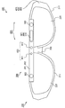
- FIG. 1 is a schematic external perspective view showing an example of an eyeglass display device 100.
- FIG. 3 is a schematic diagram illustrating an example of a configuration of a control unit 450 of the operation system 400.
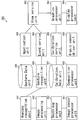
- FIG. 4 is a flowchart showing a flow of processing in the operation system 400. It is a schematic diagram which shows the concept according to the flowchart of FIG. 4 is a schematic perspective view for explaining a detection area of an infrared detection unit 410 and a virtual display area of a pair of transflective displays 220.
- FIG. FIG. 7 is a top view of FIG. 6.
- FIG. 7 is a side view of FIG. 6.
- FIG. 4 is a schematic diagram illustrating an example of display on a transflective display 220 of the eyeglass display device 100.
- FIG. It is a schematic diagram which shows an example (a) of the visual field of the transflective display 220, and an example (b) of a display of the translucent display 220.
- gesture recognition It is a schematic diagram which shows an example of gesture recognition. It is a schematic diagram which shows the other example of gesture recognition. It is a schematic diagram which shows the other example of gesture recognition. It is a schematic diagram which shows the other example of gesture recognition. It is a schematic diagram which shows the other example of gesture recognition. It is a schematic diagram which shows the other example of gesture recognition. It is a schematic diagram which shows the other example of gesture recognition. It is a schematic diagram which shows the other example of gesture recognition. It is a schematic diagram which shows the other example of gesture recognition. It is a schematic diagram which shows the other example of gesture recognition.
- the present invention is not limited to the eyeglass display device described below, but can be applied to other input / output devices, display devices, televisions, monitors, projectors, and the like.
- FIG. 1 is a schematic external front view showing an example of the basic configuration of a spectacle display device 100 according to an embodiment
- FIG. 2 is a schematic external perspective view showing an example of the spectacle display device 100.
- the glasses display device 100 is a glasses-type display device. As will be described later, the eyeglass display device 100 is used by being worn on the user's face.
- the eyeglass display device 100 mainly includes an eyeglass unit 200, a communication system 300, and an operation system 400.
- the spectacle unit 200 includes a spectacle frame 210 and a pair of transflective displays 220.
- the spectacle frame 210 mainly includes a rim unit 211 and a temple unit 212.
- a pair of transflective displays 220 is supported by the rim unit 211 of the spectacle frame 210.
- the pair of transflective displays 220 is provided on the rim unit 211 in the spectacle display device 100, but the present invention is not limited to this, and a normal sunglasses lens is provided on the rim unit 211 of the spectacle display device 100.
- lenses such as an ultraviolet cut lens or a spectacle lens may be provided, and a single transflective display 220 or a pair of transflective displays 220 may be provided separately. Further, the transflective display 220 may be embedded in a part of the lenses.
- the present embodiment is not limited to the eyeglass type, and can be used for a hat type or any other head mounted display device as long as it is a type that can be worn on the human body and disposed in the field of view of the wearer. .
- the communication system 300 includes a battery unit 301, an antenna module 302, a camera unit 303, a speaker unit 304, a GPS (Global Positioning System) unit 307, a microphone unit 308, a SIM (Subscriber Identity Module Card) unit 309, and a main unit 310.
- the camera unit may be provided with a CCD sensor.
- the speaker unit 304 may be a normal earphone or a bone conduction earphone.
- the SIM unit 309 includes an NFC (Near Field Communication) unit and other contact IC card units, and a non-contact IC card unit.
- the communication system 300 includes at least one of the functions of a mobile phone, a smartphone, and a tablet terminal. Specifically, it includes a telephone function, an Internet function, a browser function, a mail function, an imaging function, and the like. Therefore, the user can use a call function similar to that of a mobile phone by using the eyeglass display device 100 with the communication device, the speaker, and the microphone. Further, since it is a glasses type, it is possible to make a call without using both hands.
- the operation system 400 includes an infrared detection unit 410, a gyro sensor unit 420, an acceleration detection unit 430, and a control unit 450.
- the infrared detection unit 410 mainly includes an infrared irradiation element 411 and an infrared detection camera 412.
- FIG. 3 is a schematic diagram illustrating an example of the configuration of the control unit 450 of the operation system 400.
- the control unit 450 includes an image sensor calculation unit 451, a depth map calculation unit 452, an image processing unit 453, an anatomical recognition unit 454, a gesture data recording unit 455, a gesture identification unit 456, calibration data. It includes a recording unit 457, a composite arithmetic unit 458, an application software unit 459, an event service unit 460, a calibration service unit 461, a display service unit 462, a graphic arithmetic unit 463, a display arithmetic unit 464, and a six-axis drive driver unit 465.
- control unit 450 need not include all of the above, and may include one or more units as necessary.
- the gesture data recording unit 455 and the calibration data recording unit 457 may be arranged on the cloud, and the synthesis operation unit 458 may not be provided.
- FIG. 4 is a flowchart showing a flow of processing in the operation system 400
- FIG. 5 is a schematic diagram showing a concept corresponding to the flowchart of FIG.
- the target data is acquired from the infrared detection unit 410, and the depth calculation is performed by the depth map calculation unit 452 (step S1.
- the outer shape image data is processed by the image processing unit 453. (Step S2).
- the anatomical recognition unit 454 identifies anatomical features from the outline image data processed in step S2 based on the standard human body structure. Thereby, the outer shape is recognized (step S3).
- the gesture identification unit 456 identifies the gesture based on the anatomical features obtained in step S3 (step S4).
- the gesture identification unit 456 refers to the gesture data recorded in the gesture data recording unit 455 and identifies the gesture from the outer shape where the anatomical features are identified.
- the gesture identification unit 456 refers to the gesture data from the gesture data recording unit 455.
- the gesture identification unit 456 is not limited to referencing, and may refer to other arbitrary data without referring to it at all. It may be processed. As described above, the hand gesture is recognized as shown in FIG.
- the application software unit 459 and the event service unit 460 perform a predetermined event according to the gesture determined by the gesture identification unit 456 (step S5).
- the image by a photography application for example is displayed.
- the image data from the camera unit 303 may be displayed on the screen.
- the display service unit 462, the calibration service unit 461, the graphic operation unit 463, the display operation unit 464, and the composition operation unit 458 display an image on the translucent display 220 or a virtual display of the image (step).
- S6 As a result, a hand skeleton indicating a gesture is displayed as shown in FIG. 5C, and as shown in FIG. 5D, the shape and size of the photograph are changed to the shape and size of the skeleton. An image synthesized to match is displayed.
- the 6-axis drive driver unit 465 always detects signals from the gyro sensor unit 420 and the acceleration detection unit 430, and transmits the posture state to the display arithmetic unit 464.
- the 6-axis drive driver unit 465 When the user wearing the glasses display device 100 tilts the glasses display device 100, the 6-axis drive driver unit 465 always receives signals from the gyro sensor unit 420 and the acceleration detection unit 430, and displays an image. Take control. In this control, the display of the image may be kept horizontal, or the display of the image may be adjusted according to the inclination.
- FIG. 6 is a schematic perspective view for explaining a detection region of the infrared detection unit 410 and a virtual display region of the pair of transflective displays 220
- FIG. 7 is a top view of FIG. 6
- FIG. FIG. 7 is a side view of FIG. 6.
- a three-dimensional orthogonal coordinate system including an x-axis, a y-axis, and a z-axis is defined.
- the x-axis arrows in the following figures indicate the horizontal direction.
- the y-axis arrow points in the vertical direction or the long axis direction of the user's body.
- the z-axis arrow points in the depth direction.
- the z-axis positive direction refers to the direction of greater depth.
- the direction of each arrow is the same in other figures.
- a three-dimensional space detection area (3D space) 4103 ⁇ / b> D that can be detected by the infrared detection unit 410 of the operation system 400 is provided.
- the three-dimensional space detection area 4103D is formed of a conical or pyramidal three-dimensional space from the infrared detection unit 410.
- the infrared detection unit 410 can detect the infrared rays emitted from the infrared irradiation element 411 by the infrared detection camera 412, and thus can recognize a gesture in the three-dimensional space detection region 4103D.
- one infrared detection unit 410 is provided.
- the present invention is not limited to this, and a plurality of infrared detection units 410 may be provided, or one infrared irradiation element 411 may be provided.
- a plurality of detection cameras 412 may be provided.
- the pair of transflective displays 220 displays to the user a virtual image display that is not a part of the glasses display device 100 that is actually provided, but is located away from the glasses display device 100.
- the region 2203D is visually recognized as being virtually displayed with a depth.
- the depth corresponds to the thickness in the depth direction (z-axis direction) of the virtual three-dimensional shape of the virtual image display area 2203D. Therefore, the depth is provided according to the thickness of the virtual three-dimensional shape in the depth direction (z-axis direction).
- the user recognizes the right-eye image through the right-eye semi-transmissive display 220 in the three-dimensional space area 2203DR, and the left-eye image is The light is transmitted through the transflective display 220 on the left eye side and recognized by the three-dimensional space area 2203DL.
- both recognized images are synthesized in the user's brain, and can be recognized as a virtual image in the virtual image display area 2203D.
- the virtual image display area 2203D includes a frame sequential method, a polarization method, a linear polarization method, a circular polarization method, a top-and-bottom method, a side-by-side method, an anaglyph method, a lenticular method, and a parallax barrier method.
- the liquid crystal parallax barrier method, the two-parallax method, and the multi-parallax method using three or more parallaxes are used for display.
- the virtual image display area 2203D has a spatial area shared with the three-dimensional space detection area 4103D.
- the virtual image display area 2203D since the virtual image display area 2203D exists inside the three-dimensional space detection area 4103D, the virtual image display area 2203D serves as a shared area.
- the shape and size of the virtual image display area 2203D can be arbitrarily adjusted by the display method on the pair of transflective displays 220. Moreover, as shown in FIG. 8, although the case where the infrared detection unit 410 is arrange
- FIGS. 6 to 8 are schematic diagrams illustrating other examples of the detection area and the virtual display area illustrated in FIGS. 6 to 8.
- an input / output device 900 For example, as shown in FIGS. 9 to 11, other input / output devices, display devices, televisions, monitors, and the like may be used instead of the transflective display 220 of the eyeglass display device 100.
- other input / output devices, display devices, televisions, monitors, and projectors are collectively referred to as an input / output device 900.
- the virtual image display area 2203D is output from the input / output device 900 in the negative z-axis direction, and the infrared detection unit 410 disposed at a position facing the input / output device 900 in the z-axis direction outputs the z-axis.
- a three-dimensional space detection region 4103D may be formed in the positive direction.
- a virtual image display area 2203D by the input / output device 900 is generated as a space area shared with the three-dimensional space detection area 4103D.
- a virtual image display area 2203D is output from the input / output device 900, and the infrared detection unit 410 is in the same direction as the input / output device 900 (all directions on the z-axis positive side with respect to the xy plane).
- the three-dimensional space detection region 4103D may be formed. Even in this case, the virtual image display area 2203D by the input / output device 900 is generated as a space area shared with the three-dimensional space detection area 4103D.
- the virtual image display area 2203 ⁇ / b> D may be output from the input / output device 900 in a vertically upward direction (y-axis positive direction). Also in FIG. 11, similarly to FIGS. 9 and 10, the virtual image display area 2203 ⁇ / b> D by the input / output device 900 is generated as a space area shared with the three-dimensional space detection area 4103 ⁇ / b> D.
- the input / output device 900 is arranged above the three-dimensional space detection region 4103D (y-axis positive direction side), and the virtual image display region 2203D is vertically downward (y-axis negative direction). It may be output, may be output from the horizontal direction (x-axis direction), or may be output from the rear upper side (z-axis positive direction and y-axis positive direction) like a projector or a movie theater.
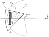
- FIGS. 12 and 13 are schematic diagrams illustrating examples of the operation area and the gesture area in the detection area.
- the user horizontally moves both hands around the shoulder joints of the right shoulder joint RP and the left shoulder joint LP, so that the area where both hands can move is surrounded by a dotted line.
- the moving area L and the moving area R become the same.
- the user vertically moves both hands around the shoulder joints of the right shoulder joint RP and the left shoulder joint LP, so that the area where both hands can move is surrounded by a dotted line.
- the moving area L and the moving area R become the same.
- the user has a spherical shape (having an arch-shaped curved surface convex in the depth direction) with both hands rotating around the right shoulder joint RP and the left shoulder joint LP, respectively. Can be moved.
- the three-dimensional space detection area 4103D by the infrared detection unit 410 the area where the virtual image display area may exist (the virtual image display area 2203D is illustrated in FIG. 12), the arm movement area L, and the movement area R are combined.
- a space area that overlaps with the selected area is set as the operation area 410c.
- a portion other than the operation region 410c in the three-dimensional space detection region 4103D and a portion overlapping with the combined region of the arm movement region L and the movement region R is set as the gesture region 410g.
- the operation region 410c has a three-dimensional shape in which the surface farthest in the depth direction is a curved surface curved in an arch shape convex in the depth direction (z-axis positive direction), whereas the virtual image display region 2203D has a depth of The surface farthest in the direction has a three-dimensional shape that is a plane.
- the user feels uncomfortable in the operation.
- adjustment is performed by a calibration process. Details of the calibration process will be described later.
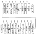
- FIG. 14 is a flowchart for explaining the calibration process.
- a calibration process is performed to facilitate the operation in the virtual image display area 2203D by a recognition process described later.
- the finger length, hand length, and arm length that are different for each user are also adjusted.
- the user wears the eyeglass display device 100 and extends both arms to the maximum.
- the infrared detection unit 410 recognizes the maximum area of the operation area 410c (step S11). That is, since the length of the finger, the length of the hand, and the length of the arm, which are different for each user, are different depending on the user, the operation area 410c is adjusted.
- the display position of the virtual image display area 2203D is determined (step S12). That is, if the virtual image display area 2203D is arranged outside the operation area 410c, the operation by the user becomes impossible, so the virtual image display area 2203D is arranged inside the operation area 410c.
- the maximum area of the gesture area 410g is set in a position that does not overlap the display position of the virtual image display area 2203D within the three-dimensional space detection area 4103D of the infrared detection unit 410 of the eyeglass display device 100 (step S13).
- the gesture region 410g is preferably arranged so as not to overlap the virtual image display region 2203D and has a thickness in the depth direction (z-axis positive direction).
- the operation area 410c, the virtual image display area 2203D, and the gesture area 410g are set by the above method.
- step) S14 When it is determined that the user's finger, hand, or arm exists outside the virtual image display area 2203D in the operation area 410c, rounding is performed so that the user's finger, hand, or arm exists inside the virtual image display area 2203D (step) S14).
- both hands remain in the virtual image display area 2203D. Without any deviation in the depth direction (z-axis positive direction). Further, at the end of the virtually displayed image, it is not determined that both hands are present in the virtual image display area 2203D unless both arms are extended to the maximum. Therefore, if the signal from the infrared detection unit 410 is used without processing, even if the user moves away from the virtual image display area 2203D, it is difficult for the user to experience such a state.
- the signal from the infrared detection unit 410 is processed so as to correct the hand protruding outside from the virtual image display area 2203D within the virtual image display area 2203D. To do. As a result, the user can operate from the center to the end of the flat virtual image display area 2203D having a depth with both arms extended to the maximum or slightly bent.
- the virtual image display area 2203D is made up of a three-dimensional space area whose plane farthest in the depth direction is a plane, but is not limited to this, and is the plane area farthest in the depth direction. It is good also as consisting of the three-dimensional space area
- the transflective display 220 displays a rectangular image in the virtual image display area 2203D. For example, as shown in FIG. 5B, a rectangular image is displayed (step S15). Subsequently, display is performed when the periphery of the image is surrounded by a finger on the transflective display 220 (step S16).
- a finger-shaped image may be displayed lightly in the vicinity of the image, or an instruction may be transmitted from the speaker to the user by voice instead of being displayed on the transflective display 220.
- the user places his / her finger on the portion where the image can be seen as shown in FIG. Then, the correlation between the display area of the virtual image display area 2203D and the infrared detection unit 410 is automatically adjusted (step S17).
- a rectangle is formed with a finger, and is matched with the rectangle thus determined and the rectangle of the outer edge of the image.
- the rectangular viewing size and position determined by the finger are matched with the rectangular viewing size and position of the outer edge of the image.
- the method of determining the shape with the finger is not limited to this, and any other method such as a method of tracing the outer edge of the displayed image with a finger, a method of pointing a plurality of points on the outer edge of the displayed image with a finger, etc. It may be. Moreover, you may perform these methods about the image of several sizes.
- FIG. 15 is a schematic diagram illustrating an example of finger recognition.
- 15A is an enlarged view of the vicinity of the tip of the finger
- FIG. 15B is an enlarged view of the vicinity of the base of the finger.
- FIG. 16 is a flowchart illustrating an example of finger recognition processing.
- the device is initialized (step S21).
- the infrared ray irradiated from the infrared irradiation element 411 and reflected by the hand is detected by the infrared detection camera 412 (step S22).
- the image data is replaced with a distance in units of pixels by the infrared detection unit 410 (step S23).
- the brightness of infrared rays is inversely proportional to the cube of the distance.
- a depth map is created (step S24).
- an appropriate threshold value is provided for the created depth map.
- the image data is binarized (step S25), that is, noise in the depth map is removed.
- a polygon having about 100 vertices is created from the binarized image data (step S26).
- a low-pass filter (LPF) so the vertex becomes smooth, by creating a new polygon having more vertexes p n, it extracts the outline OF hand shown in FIG. 15 (step S27).
- the number of vertices extracted to create a polygon from the binarized data in step S26 is about 100.
- the number of vertices is not limited to this, and 1000 or any other arbitrary number is used. It may be a number.
- step S28 From the set of vertices p n of new polygons created in step S27, using Convex Hull, it extracts the hull (step S28). Thereafter, a shared vertex p 0 between the new polygon created in step S27 and the convex hull created in step S28 is extracted (step S29).
- the shared vertex p 0 itself extracted in this way can be used as the finger tip point. Further, another point calculated based on the position of the vertex p 0 may be used as the tip point of the finger. For example, it is also possible to calculate the center of the inscribed circle of the contour OF as the tip points P0 at the vertex p 0 as shown in FIG. 15 (A).
- a vector of the reference line segment PP 1 passing through the pair of left and right vertices p 1 adjacent to the vertex p 0 is calculated.
- the side pp 2 connecting the vertex p 1 and the adjacent vertex p 2 is selected, and its vector is calculated.
- the vertex p n constituting the outer OF was selected, and its vector is calculated.
- Examined the reference line segment PP 1 direction by the processing direction and step S30 of each side determines that the sides pp k comprising parallel close to the reference line segment PP 1 is present at the position of the crotch of the finger.
- the root point P1 of the finger is calculated (step S30).
- a finger skeleton is obtained by connecting the finger tip point P0 and the finger root point P1 with a straight line (step S31).
- the extension direction of the finger can be recognized.
- skeletons for all fingers are obtained. Thereby, the hand pose can be recognized. That is, it is possible to recognize which of the thumb, the index finger, the middle finger, the ring finger, and the little finger is spread and which finger is gripped.
- a difference in hand pose is detected in comparison with the image data of several frames performed immediately before (step S32). That is, the hand movement can be recognized by comparing with the image data of the last several frames.
- the recognized hand shape is delivered to the event service unit 460 as gesture data (step S33).
- step S34 the application software unit 459 performs a behavior corresponding to the event.
- the display service unit 462 requests drawing in the three-dimensional space (step S35).
- the graphic operation unit 463 refers to the calibration data recording unit 457 using the calibration service unit 461, and corrects the display (step S36).
- display is performed on the transflective display 220 by the display arithmetic unit 464 (step S37).
- the root point of the finger is detected by the process of step S30 and the process of step S31, but the root point detection method is not limited to this.
- the length of the reference line segment PP 1 that connects a pair of adjacent vertices p 1 on one side and the other side of the vertex p 0 is calculated.
- the length of a line connecting between the pair of vertices p 2 at the one side and the other side is calculated.
- the length of the line segment connecting the pair of vertices on the one side and the other side is calculated in the order from the vertex located closer to the vertex p 0 to the vertex located further away.
- Such line segments are approximately parallel to each other without intersecting within the outer shape OF.
- the root point can be determined by detecting the line segment that does not exceed the predetermined amount and the farthest from the apex p 0 and extracts one point on the detected line segment. .
- FIG. 17 is a schematic diagram illustrating an example of palm recognition.
- the maximum inscribed circle C inscribed in the outer shape OF of the image data is extracted.
- the position of the maximum inscribed circle C can be recognized as the palm position.
- FIG. 18 is a schematic diagram showing an example of thumb recognition.
- the thumb has characteristics different from the other four fingers of the index finger, the middle finger, the ring finger, and the little finger.
- ⁇ 1 involving the thumb tends to be the largest.
- ⁇ 11 involving the thumb tends to be the largest.
- the thumb is determined based on such a tendency. As a result, it is possible to determine whether it is the right hand or the left hand, or the front or back of the palm.
- arm recognition Next, arm recognition will be described. In the present embodiment, arm recognition is performed after any of a finger, palm, and thumb is recognized. Note that the arm recognition may be performed before recognizing any one of the finger, the palm, and the thumb, or at least one of them.
- the polygon is extracted in a larger area than the hand-shaped polygon of the image data.
- the process of steps S21 to S27 is performed in a range of 5 cm to 100 cm in length, and more preferably in a range of 10 cm to 40 cm to extract the outer shape.
- a rectangular frame circumscribing the extracted outer shape is selected.
- the square frame is a parallelogram or a rectangle.
- the extension direction of the arm can be recognized from the extension direction of the long side, and the direction of the arm can be determined from the direction of the long side. I can do it.
- the movement of the arm may be detected in comparison with the image data of the previous few frames.
- the finger, palm, thumb, and arm are detected from the two-dimensional image.
- the present invention is not limited to the above, and the infrared detection unit 410 may be further added, and only the infrared detection camera 412 is used. May be added to recognize a three-dimensional image from a two-dimensional image. As a result, the recognition accuracy can be further increased.
- FIG. 19 is a schematic diagram illustrating an example of display on the transflective display 220 of the eyeglass display device 100.
- an advertisement 221 is displayed on a part of the transflective display 220 of the glasses display device 100, a map 222 is displayed on a part of the display, and the other part is a half of the glasses display device 100.
- a landscape 223 is visually recognized through the transmissive display 220, and a weather forecast 224 and a time 225 are also displayed.
- FIG. 20A illustrates an example of the field of view of the translucent display 220
- FIG. 20B illustrates an example of the display of the translucent display 220.
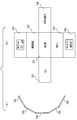
- the display that can be viewed by the eyeglass display device 100 is composed of a plurality of displays 701 to 707.
- a plurality of displays are segments forming a part of a continuous image in which all of them are integrated. By switching the visible portion of the continuous image, a switching display is performed in which a plurality of displays are smoothly transitioned without being interrupted.
- displays 703, 702, 701, 704, and 705 are provided in the vertical direction, and displays 706 and 707 are provided on the left and right with the display 701 as the center.
- the displays 701 to 707 can be freely deleted or changed by the user, and other displays can be added.
- the displays 701 to 707 are seamless continuous images, but the display to be switched may be an independent non-continuous image.
- the display 701 is displayed when the posture of the eyeglass display device 100 is horizontal, that is, when the user wears the eyeglass display device 100 and faces horizontally.
- a display 702 is displayed. That is, the direction in which the user faces is recognized based on a signal from at least one of the gyro sensor unit 420 and the acceleration detection unit 430 in the eyeglass display device 100.
- the display 702 may display a screen of a face recognition application, for example.
- a display 703 is displayed.
- a weather forecast may be displayed on the display 703.
- other sky information may be displayed on the display 703.
- an image of a constellation may be displayed depending on the time zone.
- a display 704 for example, a mail screen
- Display 705 for example, a map
- a display 706 for example, an Internet browser
- a display 707 for example, a call screen
- the display 701 to the display 707 are switched based on a signal from at least one of the gyro sensor unit 420 and the acceleration detection unit 430.
- the present invention is not limited to this. Switching may be performed by palm and arm recognition.
- the gyro sensor unit is a condition for switching at least one of the display 701 to the display 702, the display 701 to the display 704, the display 701 to the display 707, and the display 701 to the display 706.
- the level of the signal from at least one of 420 and the acceleration detection unit 430 may be set higher. Thereby, it is possible to prevent the display 701 from being switched to another display in a short time during walking. Moreover, when turning around urgently, a setting that is not particularly switched may be provided.
- the sky information display 703 and the map information display 705 may be panoramic displays. In this case, the displays 703 and 705 may be scrolled in accordance with the movement in the left-right direction.
- FIG. 21 is a schematic diagram illustrating an example of a predetermined event occurrence
- FIG. 22 is a schematic diagram illustrating another example of the event occurrence of FIG. 21,
- FIG. 23 is a schematic diagram illustrating an example of another event occurrence.
- the shape of the hand H1 detected by the infrared detection unit 410 is displayed on the virtual image. Further, when the user's hand is away from the operation area 410c, a shadow H2 having the shape of the hand H1 is displayed as an example of the event. Thereby, the user can easily recognize that the hand is present in the gesture region 410g.
- the shape of the hand H1 detected by the infrared detection unit 410 is displayed in the virtual image, and a shadow H3 that is darker than the shadow H2 has a small area around the shape of the hand H1. Is displayed. Therefore, the user can easily recognize that the hand is closer to the operation area 410c than in the case of FIG. Further, when the hand is in the operation area 410c, the shadows H2 and H3 are not displayed.
- the user does not need to search the operation area 410c by trial and error or groping. That is, the distance to the operation area 410c can be easily recognized based on the density of the shadow and how the hand shape deviates from the shadow.
- the circle display H4 may be performed on the fingertip.
- the present invention is not limited to this, and a ripple is generated in the display when it is within the operation area 410c.
- the vibration generation device may be provided in the eyeglass display device 100 to generate vibration, sound may be generated, or the display may be changed depending on at least one of the display blinking mode and the lighting illuminance. Good.
- the distance to the operation area 410c may be represented by a blinking interval, and the distance to the operation area 410c may be represented by lighting illuminance.
- lighting in darker colors red, black, purple, etc.
- lighting in lighter colors blue, yellow, pink, etc.
- Other human senses typically visual, auditory and tactile) ) May be triggered by any event.
- the virtual image display can be operated.
- the virtual image display can be enlarged or reduced, the display can be scrolled, or a point can be selected.
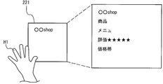
- additional display may be performed by touching the display of the advertisement 221.
- the advertisement 221 displays information such as merchandise and services of the store.
- more detailed information regarding the store may be additionally displayed.
- the advertisement 221 may be an image of the store itself taken by the camera unit 303, or automatically starts store recognition based on image data of the store by the camera unit 303.
- the store recognition application It may be recognition result information displayed on the screen.
- Display in parody mode In addition, as shown in FIG. 25, when a logo mark of one company (XX company) is displayed on the transflective display 220, a competition or non-competition can be achieved by touching the logo mark on the screen. Information related to other companies ( ⁇ company) can be displayed. In this case, for example, a logo of the other company may be displayed as a parody mode.
- a menu screen V1 is displayed between the thumb and index finger. Also good.
- a predetermined image V2 may be displayed between the index finger and the middle finger.
- the face recognition application when the hand H1 is lightly opened and moved in the direction of the arrow by greeting, the face recognition application is automatically activated. Face recognition is automatically started based on the face data of the other person acquired by the camera unit 303, and information such as name, company name, job title, date and place of the last meeting is displayed on the face recognition application screen V3. . Further, a flag may be set each time the same person is recognized by the recognition of the face recognition application, and the number of flags may be displayed on the face recognition application screen V3. In this case, the background and color of the face recognition application screen V3 may be varied depending on the number of flags.
- the SNS (SOCIAL NETWORKING SERVICE) application can be automatically started and the SNS application screen V5 can be displayed.
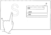
- the kanji application is activated and the index finger of the hand H1 is recognized to display an additional brush image at the position of the index finger. .
- the sword application is activated, and a sword image is additionally displayed at the position of the hand on the sword, and the virtual image display screen V7 is cut. it can.
- the eyeglass display device 100 can be worn on the human body, and is displayed on the transflective display 220 according to the acceleration caused by the movement of the human body detected by the acceleration detection unit 430. 701 to 707 can be switched.
- the plurality of displays 701 to 707 are seamless, by changing a display portion of a continuous image formed by integrating the plurality of displays 701 to 707, The plurality of displays 701 to 707 can be smoothly transitioned without being interrupted.
- the eyeglass display device 100 is a head-mounted display device, images can be switched by the movement of the head, and both hands can be used freely.
- the eyeglass display device 100 includes the gyro sensor unit 420, it is possible to switch images with high accuracy according to the rotational motion.
- the eyeglass display device 100 can display the map image 705 when the gyro sensor unit 420 detects a lower direction than the horizontal direction. For this reason, since a map is displayed by dropping a line of sight toward the ground, a natural experience can be obtained.
- the eyeglass display device 100 can be scrolled according to the horizontal direction angle if the map display 705 is a panoramic display. For this reason, since the direction of a map changes according to the direction which turns a gaze, or the direction which moves a body, a natural bodily sensation can be acquired.
- the eyeglass display device 100 can display a weather forecast display 703 when an upward direction from the horizontal direction is detected. For this reason, since information about the sky is displayed by raising the line of sight toward the sky, it is possible to obtain data about the sky with a natural experience.
- the eyeglass display device 100 also includes a display 701 for displaying a menu screen, a display 702 for displaying a face recognition application screen, a call application screen for displaying a menu screen when an acceleration exceeding a predetermined amount is detected by the acceleration detection unit 430. Can be switched between a display 707 for displaying the Internet application screen, a display 706 for displaying the Internet application screen, or a display 704 for displaying the mail application screen.
- a spring can be virtually incorporated in the switching portion between the display 701 on which the menu screen is displayed and the display on the top, bottom, left and right, so that unnecessary switching due to extra movement of the human body can be prevented and stable.
- the image can be displayed.
- the eyeglass display device 100 includes the communication system 300 having a mobile phone function, a hands-free type call can be easily performed.
- the acceleration detection unit 430 corresponds to an “acceleration device”
- the transflective display 220 corresponds to a “display device”
- the displays 701 to 707 correspond to “a plurality of images”
- the gyro sensor unit. 420 corresponds to a “gyroscope”
- the eyeglass display device 100 corresponds to a “display control device”.
Landscapes
- Engineering & Computer Science (AREA)
- Physics & Mathematics (AREA)
- General Engineering & Computer Science (AREA)
- Theoretical Computer Science (AREA)
- General Physics & Mathematics (AREA)
- Human Computer Interaction (AREA)
- Optics & Photonics (AREA)
- Controls And Circuits For Display Device (AREA)
- User Interface Of Digital Computer (AREA)
Abstract
Description
特許文献1に記載の高速画像生成表示方法においては、立体構造をもつ対象を2次元画面に投影して表示する高速画像生成表示方法であって、対象の構成面は、対象座標系において、領域の大きさを少なくとも1つの要素として階層的に記述され、任意の視点から見た時の該対象の構成面を2次元画面へ投影するに際して、表示基準座標系原点または視点から対象座標系で表される該対象の任意の点までの距離を少なくとも1つのパラメータとして階層度を設定することを特徴とする。
特許文献2に記載の立体視画像生成方法は、三次元座標を有するポリゴンで構成されるオブジェクトのうち、平面視表示させるオブジェクトデータを基準カメラを原点とする基準カメラ座標系データに、立体視表示させるオブジェクトのデータを所定の視差角を有する右眼用及び左眼用視差カメラをそれぞれ原点とする右眼用及び左眼用視差カメラ座標系データに変換し、基準カメラ座標系のオブジェクトのデータと、右眼用視差カメラ座標系のオブジェクトのデータを右眼用画像データとして、ビデオメモリに描画し、基準カメラ座標系のオブジェクトのデータと、左眼用視差カメラ座標系のオブジェクトのデータを左眼用画像データとして、ビデオメモリに描画し、ビデオメモリに描画された右眼用画像データと左眼用画像データを合成して、立体視オブジェクトと平面視オブジェクトの混在する画像を立体視表示装置に表示することを特徴とする。
特許文献3に記載の方法は、ユーザの気質を示す属性を視覚表示に適用するための方法であって、ユーザの視覚表示をレンダリングするステップと、物理的な空間のデータを受信するステップであって、データが、物理的な空間内のユーザを代表しているものと、ユーザの気質を推論するために、少なくとも1つの検出可能な特徴を解析するステップと、ユーザの気質を示す属性を視覚表示に適用するステップと、を含む。
特許文献4に記載のシステムは、入力デバイスと、プロセッサに結合され、入力デバイスの方位を検出する検出器と、を備えているシステムであって、入力デバイスが、方位に対応する複数のモード方位を有し、複数のモード方位が、ジェスチャ制御システムの複数の入力モードに対応し、検出器が、ジェスチャ制御システムに結合され、方位に応答して、複数の入力モードからの入力モードの選択を自動的に制御する。
一局面に従う表示制御装置は、加速度を検知する加速度装置と、切換えにより異なる像を表示可能かつ人体に装着可能な表示装置と、を含み、表示装置は、加速度装置により検知された加速度に応じて、複数の像を切換えるものである。
第2の発明にかかる表示制御装置は、一局面に従う表示制御装置において、複数の像のうち少なくとも2の像は、シームレスであってもよい。
第3の発明にかかる表示制御装置は、一局面または第2の発明にかかる表示制御装置において、複数の像のうち少なくとも2の像がそれぞれ独立していてもよい。
この場合、切換えられるべき複数の像を別個に識別することができる。また、複数の像が3の像以上の場合、シームレスの像と、独立した像とを確実に切換えることができる。
第4の発明にかかる表示制御装置は、一局面から第3の発明のいずれかにかかる表示制御装置において、表示装置は、ヘッドマウントディスプレイであってもよい。
第5の発明にかかる表示制御装置は、一局面から第4の発明のいずれかにかかる表示制御装置において、表示制御装置は、ジャイロスコープをさらに含んでもよい。表示装置は、ジャイロスコープにより検知される水平方向角および水平方向に対する垂直方向角の少なくともいずれかに応じ、像を切換えてもよい。
第6の発明にかかる表示制御装置は、第5の発明にかかる表示制御装置において、表示装置は、ジャイロスコープにより、装着時の位置を基準とした水平方向よりも下方向が検出された場合に、地図の像を表示させてもよい。
第7の発明にかかる表示制御装置は、第6の発明にかかる表示制御装置において、地図の像は、水平方向角に応じてスクロール可能であってもよい。
第8の発明にかかる表示制御装置は、第5から第7のいずれかに記載の表示制御装置において、水平方向よりも上方向が検出された場合に、天気予報および星座の少なくともいずれかの天空情報の像を表示させてもよい。
第9の発明にかかる表示制御装置は、一局面から第8の発明にかかる表示制御装置において、表示装置は、加速度装置により所定量を超過する加速度が検出された場合に、複数の像のうち少なくとも2の像の間の切換えを、実施してもよい。
すなわち、像の切換えを望まない場合に生じる身体または頭の動作に対して、像の切換えを防止できる。
第10の発明にかかる表示制御装置は、第9の発明にかかる表示制御装置において、加速度装置により所定量を超過する加速度が検出された場合に切換えられる像の一方が、複数の像のうち、ジャイロスコープにより少なくとも装着時の位置を基準とした水平方向が検出された場合に表示される像であってもよい。
なお、像の切換え防止機能を別途設けてもよい。さらに、加速度装置およびジャイロセンサとの両機能を有するユニットを設けてもよい。
第11の発明にかかる表示制御装置は、一局面から第10の発明のいずれかにかかる表示制御装置において、表示装置が、携帯電話機能をさらに含んでもよい。
他の発明にかかる表示制御プログラムは、人体に装着可能な表示装置に用いられる表示制御プログラムであって、人体の動きの加速度を検知する加速度検知処理と、切換えにより異なる像を表示する表示処理と、加速度検知処理により検知された加速度に応じて複数の像を切換える加速度対応切換え処理とを含むものである。
第13の発明にかかる表示制御プログラムは、他の局面に従う表示制御プログラムにおいて、ジャイロスコープ処理をさらに含んでもよい。ジャイロスコープ処理は、人体の動きの角速度を検知してもよい。加速度対応切換え処理は、角速度対応切換え処理を含んでもよい。角速度対応切換え処理は、ジャイロスコープ処理によって検知された、水平方向角および水平方向に対する垂直方向角の少なくともいずれかに応じ、像を切換えてもよい。
第14の発明にかかる表示制御プログラムは、第13の発明にかかる表示制御プログラムにおいて、表示処理は、地図表示処理を含んでもよい。地図表示処理は、ジャイロスコープ処理によって装着時の位置を基準とした水平方向よりも下方向が検出された場合に、地図の像を表示させてもよい。
第15の発明にかかる表示制御プログラムは、第13または第14の発明にかかる表示制御プログラムにおいて、表示処理が、スクロール処理を含んでもよい。スクロール処理は、地図の像を、ジャイロスコープ処理によって検知された水平方向角に応じてスクロールさせてもよい。
第16の発明にかかる表示制御プログラムは、第13から第15のいずれかの発明にかかる表示制御プログラムにおいて表示処理は、天空情報表示処理を含んでもよい。天空情報表示処理は、ジャイロスコープ処理によって装着時の位置を基準とした水平方向よりも上方向が検出された場合に、天気予報および星座の少なくともいずれかの天空情報の像を表示させてもよい。
第17の発明にかかる表示制御プログラムは、他の局面から第16の発明のいずれかにかかる表示制御プログラムにおいて、スプリング処理をさらに含んでもよい。スプリング処理は、複数の像のうち少なくとも2の像の間の切換えを、加速度検出処理により所定量を超過する加速度が検出された場合に行なってもよい。
第18の発明にかかる表示制御プログラムは、他の局面から第17の発明のいずれかにかかる表示制御プログラムにおいて、通話処理をさらに含んでもよい。
さらに他の局面に従う表示制御方法は、人体に装着可能な表示装置に用いられる表示制御方法であって、人体の動きの加速度を検知する加速度検知工程と、切換えにより異なる像を表示する表示工程と、加速度検知工程により検知された加速度に応じて複数の像を切換える加速度対応切換え工程とを含むものである。
第20の発明にかかる表示制御方法は、さらに他の局面に従う表示制御方法において、ジャイロスコープ工程をさらに含んでもよい。ジャイロスコープ工程は、人体の動きの角速度を検知してもよい。加速度対応切換え工程は、角速度対応切換え工程を含んでもよい。角速度対応切換え工程は、ジャイロスコープ工程によって検知された、水平方向角および水平方向に対する垂直方向角の少なくともいずれかに応じ、像を切換えてもよい。
第21の発明にかかる表示制御方法は、第20の発明にかかる表示制御方法において、表示工程は、地図表示工程を含んでもよい。地図表示工程は、ジャイロスコープ工程によって装着時の位置を基準とした水平方向よりも下方向が検出された場合に、地図の像を表示させてもよい。
第22の発明にかかる表示制御方法は、第20または第21の発明にかかる表示制御方法において、表示工程が、スクロール工程を含んでもよい。スクロール工程は、地図の像を、ジャイロスコープ工程によって検知された水平方向角に応じてスクロールさせてもよい。
第23の発明にかかる表示制御方法は、第20から第22の発明のいずれかにかかる表示制御方法において、表示工程は、天空情報表示工程を含んでもよい。天空情報表示工程は、ジャイロスコープ工程によって装着時の位置を基準とした水平方向よりも上方向が検出された場合に、天気予報および星座の少なくともいずれかの天空情報の像を表示させてもよい。
第24の発明にかかる表示制御方法は、第19から第23の発明のいずれかにかかる表示制御方法において、スプリング工程をさらに含んでもよい。スプリング工程は、複数の像のうち少なくとも2の像の間の切換えを、加速度検出工程により所定量を超過する加速度が検出された場合に行なってもよい。
第25の発明にかかる表示制御方法は、さらに他の局面から第24の発明のいずれかにかかる表示制御方法において、通話工程をさらに含んでもよい。
220 半透過ディスプレイ
221 広告
2203D 仮想イメージ表示領域(共有領域)
300 通信システム
303 カメラユニット
410 赤外線検知ユニット
410c 操作領域
420 ジャイロセンサユニット
430 加速度検知ユニット
4103D 三次元空間検知領域
450 制御ユニット
454 解剖学的認識ユニット
456 ジェスチャ識別ユニット
460 イベントサービスユニット
461 キャリブレーションサービスユニット
701,~,707 表示
900 入出力装置
H1 手
H2,H3 陰影
RP 右肩関節
LP 左肩関節
OF 外形
pn,p0,p1 頂点
PP1 基準線分
pp2 辺
ppk 辺
P0 先端点
P1 根元点
C 最大内接円
V3 顔認識アプリ画面
V5 SNSアプリ画面
また、本発明は、以下に説明する眼鏡表示装置に限定されるものではなく、他の入出力装置、表示装置、テレビジョン、モニタ、プロジェクタ等にも適用することができる。
図1は、一実施の形態にかかる眼鏡表示装置100の基本構成の一例を示す模式的外観正面図であり、図2は、眼鏡表示装置100の一例を示す模式的外観斜視図である。
図1および図2に示すように、眼鏡ユニット200は、眼鏡フレーム210および一対の半透過ディスプレイ220からなる。眼鏡フレーム210は、主にリムユニット211、テンプルユニット212を含む。
眼鏡フレーム210のリムユニット211により一対の半透過ディスプレイ220が支持される。
また、当該レンズ類の一部に、半透過ディスプレイ220を埋め込んで設けてもよい。
次に、通信システム300について説明を行なう。
通信システム300は、バッテリーユニット301、アンテナモジュール302、カメラユニット303、スピーカユニット304、GPS(Global Positioning System)ユニット307、マイクユニット308、SIM(Subscriber Identity Module Card)ユニット309およびメインユニット310を含む。
なお、カメラユニットにはCCDセンサが備えられてよい。スピーカユニット304は、ノーマルイヤホンであってもよいし、骨伝導イヤホンであってもよい。SIMユニット309には、NFC(Near Field Communication:近距離無線通信)ユニットおよび他の接触式ICカードユニット、ならびに非接触式ICカードユニットを含む。
したがって、ユーザは、眼鏡表示装置100を用いて、通信装置、スピーカおよびマイクにより、携帯電話と同様の通話機能を使用することができる。また、眼鏡型であるので、両手を利用せず、通話を行なうことができる。
続いて、操作システム400は、赤外線検知ユニット410、ジャイロセンサユニット420、加速度検知ユニット430および制御ユニット450からなる。赤外線検知ユニット410は、主に赤外線照射素子411および赤外線検知カメラ412からなる。
ジェスチャ識別ユニット456は、ジェスチャデータ記録ユニット455に記録されたジェスチャデータを参照し、解剖学的特徴が識別された外形からジェスチャの識別を行なう。なお、ジェスチャ識別ユニット456は、ジェスチャデータ記録ユニット455からのジェスチャデータを参照することとしているが、参照することに限定されず、他の任意のデータを参照してもよく、全く参照することなく処理してもよい。
以上により、図5(a)に示すように、手のジェスチャを認識する。
これによって、図5(b)に示すように、たとえば写真アプリによる画像が表示される。この際、当該画面には、カメラユニット303からの撮像データが表示されてよい。
次に、操作システム400の赤外線検知ユニット410の検知領域と、一対の半透過ディスプレイ220の仮想表示領域との関係について説明を行なう。
図6は、赤外線検知ユニット410の検知領域と、一対の半透過ディスプレイ220の仮想表示領域とを説明するための模式的斜視図であり、図7は図6の上面図であり、図8は、図6の側面図である。
三次元空間検知領域4103Dは、赤外線検知ユニット410からの円錐状または角錐状の三次元空間からなる。
また、本実施の形態においては、赤外線検知ユニット410を1個設けることとしているが、これに限定されず、赤外線検知ユニット410を複数個設けてもよいし、赤外線照射素子411を1個、赤外線検知カメラ412を複数個設けてもよい。
すなわち、実際には眼鏡表示装置100の半透過ディスプレイ220に表示されるものの、ユーザは、右目のイメージは右目側の半透過ディスプレイ220を透過し三次元空間領域2203DRで認識し、左目のイメージは左目側の半透過ディスプレイ220を透過し三次元空間領域2203DLで認識する。その結果、認識された両イメージがユーザの脳内で合成されることにより、仮想イメージ表示領域2203Dで仮想イメージとして認識することができる。
また、図8に示すように、一対の半透過ディスプレイ220よりも赤外線検知ユニット410が上方(y軸正方向)に配設されている場合について説明しているが、鉛直方向(y軸方向)に対して、赤外線検知ユニット410の配設位置が半透過ディスプレイ220よりも下方(y軸負方向)または半透過ディスプレイ220と同位置であっても、同様に、仮想イメージ表示領域2203Dは、三次元空間検知領域4103Dと共有する空間領域を有する。
続いて、図9から図11は、図6から図8において示した検知領域と仮想表示領域との他の例を示す模式図である。
この場合、入出力装置900による仮想イメージ表示領域2203Dが、三次元空間検知領域4103Dと共有の空間領域として生じる。
この場合でも、入出力装置900による仮想イメージ表示領域2203Dが、三次元空間検知領域4103Dと共有の空間領域として生じる。
続いて、検知領域における操作領域とジェスチャ領域とについて説明する。図12および図13は、検知領域における操作領域と、ジェスチャ領域との一例を示す模式図である。
また、三次元空間検知領域4103D内における操作領域410c以外の部分で、かつ腕の移動領域Lおよび移動領域Rを合わせた領域と重なる部分をジェスチャ領域410gとして設定する。
次いで、キャリブレーション処理について説明を行なう。図14は、キャリブレーション処理の説明を行なうためのフローチャートである。
また、キャリブレーション処理には、ユーザの個々で異なる指の長さ、手の長さ、腕の長さの調整も行なう。
すなわち、ユーザによりユーザの個々で異なる指の長さ、手の長さ、腕の長さが異なるので、操作領域410cの調整を行なうものである。
なお、ジェスチャ領域410gは、仮想イメージ表示領域2203Dと重ならないように配置しかつ深さ方向(z軸正方向)に厚みを持たせることが好ましい。
そのため、赤外線検知ユニット410からの信号を無処理のまま使用すると、ユーザは、手先が仮想イメージ表示領域2203Dから外れたとしても、そのような状態であることを体感しにくい。
その結果、ユーザは、両腕を最大限に伸ばした状態、または少し曲げた状態で、奥行きのある平面状の仮想イメージ表示領域2203D内の中央部から端部まで操作することができる。
続いて、半透過ディスプレイ220に、像の周囲を指で囲んでくださいと、表示を行なう(ステップS16)。ここで、像の近傍に指の形の像を薄く表示してもよいし、半透過ディスプレイ220に表示を行なう代わりにスピーカから音声により指示をユーザに伝えてもよい。
なお、上記においては、指で矩形を形作り、そのように定められた矩形と、像の外縁の矩形にあわせる。このことによって、指により定められた矩形の視認サイズおよび位置と像の外縁の矩形の視認サイズ及び位置とを合わせることとした。しかしながら、指によって形状を定める手法はこれに限定されず、表示された像の外縁を指でなぞる手法、表示された像の外縁上の複数の点を指で指し示す手法等、他の任意の手法であってもよい。また、これらの手法を複数のサイズの像について行ってもよい。
次いで、指認識について説明を行い、その後掌認識、腕認識の順で説明を行なう。図15は、指認識の一例を示す模式図である。図15において、(A)は指の先端付近の拡大図であり、(B)は指の根元付近の拡大図である。図16は、指認識の処理の一例を示すフローチャートである。
次に、赤外線検知ユニット410により画像データをピクセル単位で距離に置き換える(ステップS23)。この場合、赤外線の明るさは、距離の三乗に反比例する。これを利用し、デプスマップを作成する(ステップS24)。
続いて、二値化した画像データから約100個の頂点を持つポリゴンを作成する(ステップS26)。そして、頂点が滑らかになるようにローパスフィルタ(LPF)により、より多くの頂点pnを有する新たな多角形を作成することによって、図15に示す手の外形OFを抽出する(ステップS27)。
なお、本実施の形態においては、ステップS26において二値化したデータからポリゴンを作成するために抽出する頂点の数を約100個としているが、これに限定されず、1000個、その他の任意の個数であってもよい。
その後、ステップS27で作成された新たな多角形と、ステップS28で作成された凸包との共有の頂点p0を抽出する(ステップS29)。このように抽出された共有の頂点p0自体を指の先端点として用いることができる。
さらに、頂点p0の位置に基づいて算出される他の点を指の先端点として用いてもよい。例えば、図15(A)に示すように頂点p0における外形OFの内接円の中心を先端点P0として算出することもできる。
全ての指について同様の処理を行なうことで、全ての指のスケルトンを得る。これにより、手のポーズを認識することができる。すなわち、親指、人差し指、中指、薬指、小指のいずれの指が広げられ、いずれの指が握られているかを認識することができる。
グラフィック演算ユニット463は、キャリブレーションサービスユニット461を用いてキャリブレーションデータ記録ユニット457を参照し、表示の補正を行なう(ステップS36)。
最後に、ディスプレイ演算ユニット464により半透過ディスプレイ220に表示を行なう(ステップS37)。
次いで、図17は、掌認識の一例を示す模式図である。
次いで、腕認識について説明を行なう。本実施の形態において、腕認識は、指、掌および親指のいずれかを認識した後に実施する。なお、腕認識は、指、掌および親指のいずれかを認識する前、またはそれらの少なくともいずれかと同時に実施してもよい。
その後、抽出した外形に外接する四角枠を選定する。本実施の形態においては、当該四角枠は、平行四辺形または長方形からなる。
この場合、平行四辺形または長方形は、対向する長辺を有するので、長辺の延在方向から腕の延在方向を認識することができ、長辺の向きから腕の向きを判定することが出来る。なお、ステップS32の処理と同様に、直前の数フレームの画像データと比較して、腕の動きを検知させてもよい。
次に、図19は、眼鏡表示装置100の半透過ディスプレイ220の表示の一例を示す模式図である。
次に、眼鏡表示装置100の半透過ディスプレイ220に表示される表示の一例について説明を行なう。図20(a)は、半透過ディスプレイ220の視野の一例、図20(b)は、半透明ディスプレイ220の表示の一例を説明する図である。
図20に示すように、縦方向に表示703、702、701、704、705の表示が設けられており、表示701を中央として、左右に表示706,707が設けられる。なお、当然のことながら、当該表示701,~,707は、ユーザによって自由に削除または変更することができ、さらに他の表示を追加することもできる。
なお、本実施の形態においては、表示701,~,707はシームレスに連続した画像であるが、切換えされるべき表示は、それぞれが独立した非連続の像であってもよい。
一方、天空情報の表示703および地図情報の表示705はパノラマ表示であってよく、この場合、左右方向の動きに伴ってそれら表示703,705をスクロールさせてよい。
続いて、指、掌、手、腕が操作領域410cに存在する場合と、ジェスチャ領域410gに存在する場合との違いをユーザが認識し易いように、所定のイベントを発生させる。以下、所定のイベントについて説明を行なう。図21は、所定のイベント発生の一例を示す模式図であり、図22は、図21のイベント発生の他の例を示す模式図であり、図23は、他のイベント発生の一例を示す模式図である。
これにより、ユーザは、ジェスチャ領域410gに手が存在することを容易に認識できる。
以上の指、掌、腕認識およびイベント発生を伴う眼鏡表示装置100の使用態様について説明する。
例えば、広告221には、店舗の、商品、サービス等の情報が表示されている。ユーザがその広告221をタッチした場合、当該店舗に関するさらに詳しい情報を追加表示させてもよい。たとえば、飲食店の場合には、当該飲食店の代表メニュ、ユーザからの評価、価格帯等を表示させてもよい。
なお、広告221は、店舗をカメラユニット303で撮影された像そのものであってもよいし、カメラユニット303による当該店舗の撮像データに基づいて店舗認識を自動で開始し、その結果、店舗認識アプリ画面に表示された認識結果情報であってもよい。
また、図25に示すように、半透過ディスプレイ220に一の企業(○○社)のロゴマークが表示されている際に、画面中のロゴマークにタッチ等行なうことで、競合又は非競合の他の企業(△△社)に関連する情報を表示させることができる。この場合、例えばパロディモードとして、当該他の企業のロゴを表示させてもよい。
また、ユーザがジェスチャ領域410g内で所定の手のポーズを作ることにより、予め設定された動作が実施される。図26から図33は、ジェスチャ認識の例を示す模式図である。
すなわち、像の切換えを望まない場合に生じる頭の動作に対して、像の切換えを防止できる。つまり、正面を向いている場合(すなわちメニュ画面が表示される表示701が表示されている場合)には不必要な切換えを防止することができ、安定して像を表示することができる。
Claims (25)
- 加速度を検知する加速度装置と、
切換えにより異なる像を表示可能かつ人体に装着可能な表示装置と、を含み、
前記表示装置は、前記加速度装置により検知された加速度に応じて、複数の像を切換える、表示制御装置。 - 前記複数の像のうち少なくとも2の像がシームレスである、請求項1に記載の表示制御装置。
- 前記複数の像のうち少なくとも2の像がそれぞれ独立している、請求項1または2に記載の表示制御装置。
- 前記表示装置がヘッドマウントディスプレイである、請求項1から3のいずれか1項に記載の表示制御装置。
- ジャイロスコープをさらに含み、
前記表示装置は、水平方向角および水平方向に対する垂直方向角の少なくともいずれかに応じて前記像を切換える、請求項1から4のいずれか1項に記載の表示制御装置。 - 前記表示装置は、前記ジャイロスコープにより、装着時の位置を基準とした水平方向よりも下方向が検出された場合に、地図の像を表示させる、請求項5に記載の表示制御装置。
- 前記表示装置は、前記水平方向角に応じて前記地図の像をスクロール可能に表示する、請求項6に記載の表示制御装置。
- 前記表示装置は、前記水平方向よりも上方向が検出された場合に、天気予報および星座の少なくともいずれかの天空情報の像を表示させる、請求項5から7のいずれか1項に記載の表示制御装置。
- 前記表示装置は、前記加速度装置により所定量を超過する加速度が検出された場合に、前記複数の像のうち少なくとも2の像の間の切換えを、実施する、請求項1から8のいずれか1項に記載の表示制御装置。
- 前記少なくとも2の像の一方が、前記複数の像のうち、前記ジャイロスコープにより少なくとも装着時の位置を基準とした水平方向が検出された場合に表示される像である、請求項9に記載の表示制御装置。
- 携帯電話機能をさらに含む、請求項1から10のいずれか1項に記載の表示制御装置。
- 人体に装着可能な表示装置に用いられる表示制御プログラムであって、
人体の動きの加速度を検知する加速度検知処理と、
切換えにより異なる像を表示する表示処理と、
前記加速度検知処理により検知された加速度に応じて複数の像を切換える加速度対応切換え処理とを含む、表示制御プログラム。 - 人体の動きの角速度を検知するジャイロスコープ処理をさらに含み、
前記加速度対応切換え処理が、前記ジャイロスコープ処理によって検知された、水平方向角および水平方向に対する垂直方向角の少なくともいずれかに応じ、前記像を切換える角速度対応切換え処理を含む、請求項12に記載の表示制御プログラム。 - 前記表示処理が、前記ジャイロスコープ処理によって装着時の位置を基準とした水平方向よりも下方向が検出された場合に、地図の像を表示させる地図表示処理を含む、請求項13に記載の表示制御プログラム。
- 前記表示処理が、前記地図の像を、前記ジャイロスコープ処理によって検知された水平方向角に応じてスクロールさせるスクロール処理を含む、請求項13または14に記載の表示制御プログラム。
- 前記表示処理が、前記ジャイロスコープ処理によって装着時の位置を基準とした水平方向よりも上方向が検出された場合に、天気予報および星座の少なくともいずれかの天空情報の像を表示させる天空情報表示処理を含む、請求項13から15のいずれか1項に記載の表示制御プログラム。
- 前記複数の像のうち少なくとも2の像の間の切換えが、前記加速度検出処理により所定量を超過する加速度が検出された場合に行なわれるスプリング処理をさらに含む、請求項12から16のいずれか1項に記載の表示制御プログラム。
- 通話処理をさらに含む、請求項12から17のいずれか1項に記載の表示制御プログラム。
- 人体に装着可能な表示装置に用いられる表示制御方法であって、
人体の動きの加速度を検知する加速度検知工程と、
切換えにより異なる像を表示する表示工程と、
前記加速度検知工程により検知された加速度に応じて複数の像を切換える加速度対応切換え工程とを含む、表示制御方法。 - 人体の動きの角速度を検知するジャイロスコープ工程をさらに含み、
前記加速度対応切換え工程が、前記ジャイロスコープ工程によって検知された、水平方向角および水平方向に対する垂直方向角の少なくともいずれかに応じ、前記像を切換える角速度対応切換え工程を含む、請求項19に記載の表示制御方法。 - 前記表示工程が、前記ジャイロスコープ工程によって装着時の位置を基準とした水平方向よりも下方向が検出された場合に、地図の像を表示させる地図表示工程を含む、請求項20に記載の表示制御方法。
- 前記表示工程が、前記地図の像を、前記ジャイロスコープ工程によって検知された水平方向角に応じてスクロールさせるスクロール処理工程を含む、請求項20または21に記載の表示制御方法。
- 前記表示工程が、前記ジャイロスコープ工程によって装着時の位置を基準とした水平方向よりも上方向が検出された場合に、天気予報および星座の少なくともいずれかの天空情報の像を表示させる天空情報表示工程を含む、請求項20から22のいずれか1項に記載の表示制御方法。
- 前記複数の像のうち少なくとも2の像の間の切換えが、前記加速度検出工程により所定量を超過する加速度が検出された場合に行なわれるスプリング工程をさらに含む、請求項19から23のいずれか1項に記載の表示制御方法。
- 通話工程をさらに含む、請求項19から24のいずれか1項に記載の表示制御方法。
Priority Applications (3)
| Application Number | Priority Date | Filing Date | Title |
|---|---|---|---|
| JP2015501064A JP6333801B2 (ja) | 2013-02-19 | 2013-02-19 | 表示制御装置、表示制御プログラム、および表示制御方法 |
| US14/768,244 US9933853B2 (en) | 2013-02-19 | 2013-02-19 | Display control device, display control program, and display control method |
| PCT/JP2013/000912 WO2014128752A1 (ja) | 2013-02-19 | 2013-02-19 | 表示制御装置、表示制御プログラム、および表示制御方法 |
Applications Claiming Priority (1)
| Application Number | Priority Date | Filing Date | Title |
|---|---|---|---|
| PCT/JP2013/000912 WO2014128752A1 (ja) | 2013-02-19 | 2013-02-19 | 表示制御装置、表示制御プログラム、および表示制御方法 |
Publications (1)
| Publication Number | Publication Date |
|---|---|
| WO2014128752A1 true WO2014128752A1 (ja) | 2014-08-28 |
Family
ID=51390600
Family Applications (1)
| Application Number | Title | Priority Date | Filing Date |
|---|---|---|---|
| PCT/JP2013/000912 Ceased WO2014128752A1 (ja) | 2013-02-19 | 2013-02-19 | 表示制御装置、表示制御プログラム、および表示制御方法 |
Country Status (3)
| Country | Link |
|---|---|
| US (1) | US9933853B2 (ja) |
| JP (1) | JP6333801B2 (ja) |
| WO (1) | WO2014128752A1 (ja) |
Cited By (3)
| Publication number | Priority date | Publication date | Assignee | Title |
|---|---|---|---|---|
| JP2018151742A (ja) * | 2017-03-10 | 2018-09-27 | 株式会社デンソーウェーブ | 情報表示システム |
| CN109521835A (zh) * | 2017-09-20 | 2019-03-26 | 富士施乐株式会社 | 信息处理设备、信息处理系统和信息处理方法 |
| TWI825004B (zh) * | 2017-02-17 | 2023-12-11 | 香港商阿里巴巴集團服務有限公司 | 輸入方法、裝置、設備、系統和電腦儲存媒體 |
Families Citing this family (11)
| Publication number | Priority date | Publication date | Assignee | Title |
|---|---|---|---|---|
| WO2014128752A1 (ja) * | 2013-02-19 | 2014-08-28 | 株式会社ブリリアントサービス | 表示制御装置、表示制御プログラム、および表示制御方法 |
| US10295826B2 (en) * | 2013-02-19 | 2019-05-21 | Mirama Service Inc. | Shape recognition device, shape recognition program, and shape recognition method |
| US10146303B2 (en) * | 2015-01-20 | 2018-12-04 | Microsoft Technology Licensing, Llc | Gaze-actuated user interface with visual feedback |
| US9965029B2 (en) * | 2015-03-30 | 2018-05-08 | Sony Corporation | Information processing apparatus, information processing method, and program |
| US9677888B2 (en) * | 2015-06-11 | 2017-06-13 | SenionLab AB | Determining sensor orientation in indoor navigation |
| US10976809B2 (en) * | 2016-03-14 | 2021-04-13 | Htc Corporation | Interaction method for virtual reality |
| US10578869B2 (en) | 2017-07-24 | 2020-03-03 | Mentor Acquisition One, Llc | See-through computer display systems with adjustable zoom cameras |
| CN119148857A (zh) * | 2017-08-24 | 2024-12-17 | 麦克赛尔株式会社 | 头戴式显示装置 |
| WO2019183399A1 (en) * | 2018-03-21 | 2019-09-26 | Magic Leap, Inc. | Augmented reality system and method for spectroscopic analysis |
| EP3718087B1 (en) * | 2018-05-23 | 2025-07-23 | Samsung Electronics Co., Ltd. | Method and apparatus for managing content in augmented reality system |
| US11886646B2 (en) * | 2022-04-01 | 2024-01-30 | Snap Inc. | Personalized calibration of user interfaces |
Citations (4)
| Publication number | Priority date | Publication date | Assignee | Title |
|---|---|---|---|---|
| JP2008096867A (ja) * | 2006-10-16 | 2008-04-24 | Sony Corp | 表示装置、表示方法 |
| JP2010287004A (ja) * | 2009-06-11 | 2010-12-24 | Nikon Corp | 頭部装着型映像表示装置 |
| JP2012008290A (ja) * | 2010-06-23 | 2012-01-12 | Softbank Mobile Corp | 眼鏡型表示装置及びサーバ |
| JP2012203128A (ja) * | 2011-03-24 | 2012-10-22 | Seiko Epson Corp | 頭部装着型表示装置および頭部装着型表示装置の制御方法 |
Family Cites Families (26)
| Publication number | Priority date | Publication date | Assignee | Title |
|---|---|---|---|---|
| JP3872100B2 (ja) * | 1993-08-12 | 2007-01-24 | セイコーエプソン株式会社 | 頭部搭載型の画像表示装置 |
| JPH0831140A (ja) | 1994-07-15 | 1996-02-02 | Victor Co Of Japan Ltd | テープリール |
| JP4228646B2 (ja) | 2002-10-02 | 2009-02-25 | 株式会社セガ | 立体視画像生成方法および立体視画像生成装置 |
| US7928926B2 (en) * | 2006-06-27 | 2011-04-19 | Panasonic Corporation | Display apparatus and method for hands free operation that selects a function when window is within field of view |
| JP5125779B2 (ja) * | 2008-06-04 | 2013-01-23 | 株式会社ニコン | ヘッドマウントディスプレイ装置 |
| JP5262681B2 (ja) * | 2008-12-22 | 2013-08-14 | ブラザー工業株式会社 | ヘッドマウントディスプレイ及びそのプログラム |
| US9256282B2 (en) | 2009-03-20 | 2016-02-09 | Microsoft Technology Licensing, Llc | Virtual object manipulation |
| KR101705924B1 (ko) | 2009-05-27 | 2017-02-10 | 오블롱 인더스트리즈, 인크 | 공간 운영 시스템을 위한 공간, 다중-모드 제어 장치 |
| US8390680B2 (en) | 2009-07-09 | 2013-03-05 | Microsoft Corporation | Visual representation expression based on player expression |
| JP2011159091A (ja) * | 2010-01-29 | 2011-08-18 | Brother Industries Ltd | 表示装置 |
| JP2012141957A (ja) * | 2010-12-16 | 2012-07-26 | Canon Inc | 情報処理装置及びその制御方法とプログラム |
| US9217867B2 (en) | 2011-03-24 | 2015-12-22 | Seiko Epson Corporation | Head-mounted display device and control method for the head-mounted display device |
| US8228315B1 (en) * | 2011-07-12 | 2012-07-24 | Google Inc. | Methods and systems for a virtual input device |
| US9081177B2 (en) * | 2011-10-07 | 2015-07-14 | Google Inc. | Wearable computer with nearby object response |
| US20130117707A1 (en) * | 2011-11-08 | 2013-05-09 | Google Inc. | Velocity-Based Triggering |
| JP5365684B2 (ja) * | 2011-12-27 | 2013-12-11 | 株式会社ニコン | 制御装置、及びヘッドマウントディスプレイ装置 |
| US20160011724A1 (en) * | 2012-01-06 | 2016-01-14 | Google Inc. | Hands-Free Selection Using a Ring-Based User-Interface |
| JP2012106005A (ja) | 2012-01-25 | 2012-06-07 | Konami Digital Entertainment Co Ltd | 画像表示装置、ゲームプログラム、ゲーム制御方法 |
| JP5880115B2 (ja) * | 2012-02-17 | 2016-03-08 | ソニー株式会社 | ヘッドマウントディスプレイ、ヘッドマウントディスプレイ制御プログラム及びヘッドマウントディスプレイの制御方法 |
| US20130246967A1 (en) * | 2012-03-15 | 2013-09-19 | Google Inc. | Head-Tracked User Interaction with Graphical Interface |
| US8922481B1 (en) * | 2012-03-16 | 2014-12-30 | Google Inc. | Content annotation |
| WO2014128752A1 (ja) * | 2013-02-19 | 2014-08-28 | 株式会社ブリリアントサービス | 表示制御装置、表示制御プログラム、および表示制御方法 |
| US10295826B2 (en) * | 2013-02-19 | 2019-05-21 | Mirama Service Inc. | Shape recognition device, shape recognition program, and shape recognition method |
| DE102013207528A1 (de) * | 2013-04-25 | 2014-10-30 | Bayerische Motoren Werke Aktiengesellschaft | Verfahren zum Interagieren mit einem auf einer Datenbrille angezeigten Objekt |
| US9442631B1 (en) * | 2014-01-27 | 2016-09-13 | Google Inc. | Methods and systems for hands-free browsing in a wearable computing device |
| US9965029B2 (en) * | 2015-03-30 | 2018-05-08 | Sony Corporation | Information processing apparatus, information processing method, and program |
-
2013
- 2013-02-19 WO PCT/JP2013/000912 patent/WO2014128752A1/ja not_active Ceased
- 2013-02-19 JP JP2015501064A patent/JP6333801B2/ja active Active
- 2013-02-19 US US14/768,244 patent/US9933853B2/en active Active
Patent Citations (4)
| Publication number | Priority date | Publication date | Assignee | Title |
|---|---|---|---|---|
| JP2008096867A (ja) * | 2006-10-16 | 2008-04-24 | Sony Corp | 表示装置、表示方法 |
| JP2010287004A (ja) * | 2009-06-11 | 2010-12-24 | Nikon Corp | 頭部装着型映像表示装置 |
| JP2012008290A (ja) * | 2010-06-23 | 2012-01-12 | Softbank Mobile Corp | 眼鏡型表示装置及びサーバ |
| JP2012203128A (ja) * | 2011-03-24 | 2012-10-22 | Seiko Epson Corp | 頭部装着型表示装置および頭部装着型表示装置の制御方法 |
Cited By (7)
| Publication number | Priority date | Publication date | Assignee | Title |
|---|---|---|---|---|
| TWI825004B (zh) * | 2017-02-17 | 2023-12-11 | 香港商阿里巴巴集團服務有限公司 | 輸入方法、裝置、設備、系統和電腦儲存媒體 |
| JP2018151742A (ja) * | 2017-03-10 | 2018-09-27 | 株式会社デンソーウェーブ | 情報表示システム |
| CN109521835A (zh) * | 2017-09-20 | 2019-03-26 | 富士施乐株式会社 | 信息处理设备、信息处理系统和信息处理方法 |
| JP2019057059A (ja) * | 2017-09-20 | 2019-04-11 | 富士ゼロックス株式会社 | 情報処理装置、情報処理システム及びプログラム |
| JP7013757B2 (ja) | 2017-09-20 | 2022-02-01 | 富士フイルムビジネスイノベーション株式会社 | 情報処理装置、情報処理システム及びプログラム |
| US11763529B2 (en) | 2017-09-20 | 2023-09-19 | Fujifilm Business Innovation Corp. | Information processing apparatus, information processing system, and non-transitory computer readable medium |
| CN109521835B (zh) * | 2017-09-20 | 2024-03-22 | 富士胶片商业创新有限公司 | 信息处理设备、信息处理系统和信息处理方法 |
Also Published As
| Publication number | Publication date |
|---|---|
| US9933853B2 (en) | 2018-04-03 |
| JP6333801B2 (ja) | 2018-05-30 |
| US20150378159A1 (en) | 2015-12-31 |
| JPWO2014128752A1 (ja) | 2017-02-02 |
Similar Documents
| Publication | Publication Date | Title |
|---|---|---|
| JP6195893B2 (ja) | 形状認識装置、形状認識プログラム、および形状認識方法 | |
| JP6333801B2 (ja) | 表示制御装置、表示制御プログラム、および表示制御方法 | |
| JP6250024B2 (ja) | キャリブレーション装置、キャリブレーションプログラム、およびキャリブレーション方法 | |
| JP6177872B2 (ja) | 入出力装置、入出力プログラム、および入出力方法 | |
| JP6250025B2 (ja) | 入出力装置、入出力プログラム、および入出力方法 | |
| WO2014128751A1 (ja) | ヘッドマウントディスプレイ装置、ヘッドマウントディスプレイ用プログラム、およびヘッドマウントディスプレイ方法 | |
| JP6446465B2 (ja) | 入出力装置、入出力プログラム、および入出力方法 | |
| JP6479835B2 (ja) | 入出力装置、入出力プログラム、および入出力方法 | |
| JP2017111537A (ja) | ヘッドマウントディスプレイおよびヘッドマウントディスプレイのプログラム | |
| JP6479836B2 (ja) | 入出力装置、入出力プログラム、および入出力方法 | |
| JP2017111724A (ja) | 配管用ヘッドマウントディスプレイ |
Legal Events
| Date | Code | Title | Description |
|---|---|---|---|
| 121 | Ep: the epo has been informed by wipo that ep was designated in this application |
Ref document number: 13875397 Country of ref document: EP Kind code of ref document: A1 |
|
| ENP | Entry into the national phase |
Ref document number: 2015501064 Country of ref document: JP Kind code of ref document: A |
|
| WWE | Wipo information: entry into national phase |
Ref document number: 14768244 Country of ref document: US |
|
| NENP | Non-entry into the national phase |
Ref country code: DE |
|
| 122 | Ep: pct application non-entry in european phase |
Ref document number: 13875397 Country of ref document: EP Kind code of ref document: A1 |