WO2014129087A1 - 車両用シートのトリムカバーの固定構造及び車両用シート - Google Patents
車両用シートのトリムカバーの固定構造及び車両用シート Download PDFInfo
- Publication number
- WO2014129087A1 WO2014129087A1 PCT/JP2013/084870 JP2013084870W WO2014129087A1 WO 2014129087 A1 WO2014129087 A1 WO 2014129087A1 JP 2013084870 W JP2013084870 W JP 2013084870W WO 2014129087 A1 WO2014129087 A1 WO 2014129087A1
- Authority
- WO
- WIPO (PCT)
- Prior art keywords
- trim cover
- cushion body
- opening
- fixing structure
- cover
- Prior art date
- Legal status (The legal status is an assumption and is not a legal conclusion. Google has not performed a legal analysis and makes no representation as to the accuracy of the status listed.)
- Ceased
Links
Images













Classifications
-
- B—PERFORMING OPERATIONS; TRANSPORTING
- B60—VEHICLES IN GENERAL
- B60N—SEATS SPECIALLY ADAPTED FOR VEHICLES; VEHICLE PASSENGER ACCOMMODATION NOT OTHERWISE PROVIDED FOR
- B60N2/00—Seats specially adapted for vehicles; Arrangement or mounting of seats in vehicles
- B60N2/58—Seat coverings
- B60N2/5816—Seat coverings attachments thereof
-
- B—PERFORMING OPERATIONS; TRANSPORTING
- B60—VEHICLES IN GENERAL
- B60N—SEATS SPECIALLY ADAPTED FOR VEHICLES; VEHICLE PASSENGER ACCOMMODATION NOT OTHERWISE PROVIDED FOR
- B60N2/00—Seats specially adapted for vehicles; Arrangement or mounting of seats in vehicles
- B60N2/58—Seat coverings
- B60N2/5816—Seat coverings attachments thereof
- B60N2/5825—Seat coverings attachments thereof by hooks, staples, clips, snap fasteners or the like
-
- B—PERFORMING OPERATIONS; TRANSPORTING
- B60—VEHICLES IN GENERAL
- B60N—SEATS SPECIALLY ADAPTED FOR VEHICLES; VEHICLE PASSENGER ACCOMMODATION NOT OTHERWISE PROVIDED FOR
- B60N2/00—Seats specially adapted for vehicles; Arrangement or mounting of seats in vehicles
- B60N2/58—Seat coverings
- B60N2/5816—Seat coverings attachments thereof
- B60N2/5883—Seat coverings attachments thereof by sewing, stitching or threading
-
- B—PERFORMING OPERATIONS; TRANSPORTING
- B60—VEHICLES IN GENERAL
- B60N—SEATS SPECIALLY ADAPTED FOR VEHICLES; VEHICLE PASSENGER ACCOMMODATION NOT OTHERWISE PROVIDED FOR
- B60N2/00—Seats specially adapted for vehicles; Arrangement or mounting of seats in vehicles
- B60N2/64—Back-rests or cushions
-
- B—PERFORMING OPERATIONS; TRANSPORTING
- B60—VEHICLES IN GENERAL
- B60N—SEATS SPECIALLY ADAPTED FOR VEHICLES; VEHICLE PASSENGER ACCOMMODATION NOT OTHERWISE PROVIDED FOR
- B60N2/00—Seats specially adapted for vehicles; Arrangement or mounting of seats in vehicles
- B60N2/68—Seat frames
-
- B—PERFORMING OPERATIONS; TRANSPORTING
- B60—VEHICLES IN GENERAL
- B60N—SEATS SPECIALLY ADAPTED FOR VEHICLES; VEHICLE PASSENGER ACCOMMODATION NOT OTHERWISE PROVIDED FOR
- B60N2/00—Seats specially adapted for vehicles; Arrangement or mounting of seats in vehicles
- B60N2/68—Seat frames
- B60N2/686—Panel like structures
-
- B—PERFORMING OPERATIONS; TRANSPORTING
- B60—VEHICLES IN GENERAL
- B60N—SEATS SPECIALLY ADAPTED FOR VEHICLES; VEHICLE PASSENGER ACCOMMODATION NOT OTHERWISE PROVIDED FOR
- B60N2/00—Seats specially adapted for vehicles; Arrangement or mounting of seats in vehicles
- B60N2/75—Arm-rests
- B60N2/753—Arm-rests movable to an inoperative position
- B60N2/757—Arm-rests movable to an inoperative position in a recess of the back-rest
-
- B—PERFORMING OPERATIONS; TRANSPORTING
- B60—VEHICLES IN GENERAL
- B60R—VEHICLES, VEHICLE FITTINGS, OR VEHICLE PARTS, NOT OTHERWISE PROVIDED FOR
- B60R5/00—Compartments within vehicle body primarily intended or sufficiently spacious for trunks, suit-cases, or the like
- B60R5/006—Compartments within vehicle body primarily intended or sufficiently spacious for trunks, suit-cases, or the like stowing or holding means for elongated articles, e.g. skis inside vehicles
Definitions
- the present invention relates to a trim cover fixing structure used for a vehicle seat having a configuration in which a cushion body is covered with a trim cover.
- the present invention also relates to a vehicle seat using the trim cover fixing structure.
- Patent Document 1 a cushion body is fixed to a frame, an insert wire is embedded inside the cushion body, a locking plate is fixed to an end of an outer skin (that is, a trim cover), and the cushion body and the frame are interposed.
- a technique for fixing a trim cover by inserting a locking plate is disclosed.
- Patent Document 2 a special structure armrest retainer having a large number of protrusions is attached to a seat back frame, and a hooking member having a special structure such as a tricing wire is provided at the front end of the trim cover.
- a technique is disclosed in which the epidermis is fixed by being hooked on the protrusions of the skin.
- a bag-shaped member is formed by integral molding inside a pad (that is, a cushion body), a terminal plate is fixed to an end of a skin material (that is, a trim cover), and the terminal plate is inserted into the bag-shaped member.
- a skin material that is, a trim cover
- Patent Document 4 discloses a vehicle seat having a trunk-through structure. Specifically, a storage recess for storing the armrest is formed in a substantially central portion of the seat back, and one of the walls separating the passenger compartment and the luggage compartment among the walls forming the storage recess. An opening is provided in the section so that a long object such as a ski can be accommodated through the opening over both the luggage compartment and the passenger compartment.
- Patent Document 4 discloses a vehicle seat having a trunk-through structure as described above, but does not mention a trim cover fixing structure. Further, as described above, the trim cover fixing structure is disclosed in each of Patent Documents 1 to 3 described above, but the trunk through structure is not mentioned.
- the present invention has been made in view of the above-described problems in the conventional fixing structure of a trim cover, has a simple structure, is inexpensive, and can provide a preferable tension to the trim cover.
- An object of the present invention is to provide a fixing structure.
- Another object of the present invention is to provide a trim cover fixing structure that can be easily applied to a vehicle seat in which a recess for storing an armrest or the like is formed.
- a trim cover fixing structure for a first vehicle seat is a trim cover fixing structure used for a vehicle seat having an elastic cushion body and a trim cover covering the cushion body.
- An engagement portion fixed near the end of the trim cover and an engaged portion that engages (for example, abuts) with the engagement portion on the trim cover in a state of covering the cushion body.
- a fixing member provided with a portion, and the fixing member can apply tension to the trim cover covering the cushion body by engaging with the engaging portion.
- the trim cover is fixed to the surface of the cushion body.
- the fixing member is pressed against the engaging portion fixed in the vicinity of the end portion of the trim cover, and the trim cover is pulled by pushing the engaging portion with the fixing member.
- the trim cover can be fixed to the cushion body. In this manner, the trim cover can be fixed by the action of simply pushing the engaging portion with the fixing member, so that the fixing structure of the trim cover can be constructed very easily.
- the fixing structure of the first trim cover it is not necessary to provide an insert wire in the cushion body, and since only the engaging portion and the fixing member are used, the cost can be kept low. .
- the trim cover is fixed to the cushion body with a preferable tension applied to the trim cover, so that the trim cover can be firmly fixed.
- the engaging portion fixed near the end of the trim cover used in the vehicle seat is pushed by a fixing member such as a board (that is, a plate-like member). Since the trim cover is fixed, the trim cover fixing structure can be easily applied to the trunk through structure when a vehicle seat having a trunk through structure is adopted.
- the fixing member may be a plate-like member having a planar extension and at least a peripheral edge being plate-like. And the periphery of the plate-shaped member can be engaged with the engaging portion.
- the plate-like member can be formed by metal pressing or synthetic resin molding. If the fixing member is formed of a plate-like member and the engaging portion is pushed and expanded by the peripheral edge of the plate-like member, the trim cover integrated with the engaging portion can be fixed in an appropriate tension applied state.
- the periphery of the fixing member can be engaged with the engaging portion in a state of being inserted between the engaging portion and the trim cover.
- the engagement between the fixing member and the engaging portion can be prevented from being released, and the trim cover can be stably fixed over a long period of time.
- the fixing member may have a step in a portion inserted between the engaging portion and the trim cover. And the said engaging part can be put in this level
- the fixing member When the fixing member is inserted between the engaging portion and the trim cover, the engaging portion projects over the fixing member.
- the amount of overhang is large, the passenger may feel uncomfortable when touching this portion via the rear surface carpet or the like, which may adversely affect the quality of the vehicle seat.
- the engaging portion is accommodated by the step provided on the fixing member as in the aspect of the present invention, the amount of protrusion of the engaging portion on the fixing member can be suppressed. As a result, the vehicle seat Can improve the quality.
- the step may be formed by a step recess provided on the periphery of the fixing member.
- step difference recessed part can regulate that the said engaging part moves relatively with respect to the said fixing member.
- the engaging portion can be sewn to the trim cover and fixed to the trim cover.
- This fixing structure is very economical because it does not require any special fixing device or fixing material.
- the engaging portion may be an elongated strip-shaped member having a long side and a short side. And the said fixing member can be engaged with the long side part of the said strip
- the engaging portion can be formed of felt, press felt, or non-woven fabric. These materials can realize a good engagement state with a fixing member formed of metal or synthetic resin.
- the fixing structure of the first trim cover is a storage recess formed by using the trim cover covering the cushion body as a wall, and includes a front region of the cushion body and a rear region of the cushion body. It is possible to have a storage recess provided with an opening to be connected, and a moving member that is movable between a position stored in the storage recess and a position outside the storage recess.
- the trim cover may be provided so as to reach the rear region of the cushion body from the front region of the cushion body through the storage recess and the opening.
- the engaging portion can be fixed on the trim cover at a portion reaching the rear region of the cushion body, and the fixing member is a cover for closing the opening of the storage recess from the rear side of the cushion body.
- the cover board can be configured so that the periphery of the cover board engages with the engaging portion when the cover board is disposed at a position closing the opening of the storage recess.
- Trunk-through structure provides an opening in a vehicle seat provided between a luggage compartment and a passenger compartment, and allows a long object (for example, skis) to be placed over both the luggage compartment and the passenger compartment through the opening. This is the structure.
- a member for example, a cover board that closes a baggage passage opening in the trunk through structure can function as the fixing member, so that the vehicle basically has a trunk through structure.
- the seat can be converted to a standard type vehicle seat that does not have a trunk-through structure very easily.
- a frame member a member having an opening in the center is used to make a vehicle seat with a trunk through structure extremely easy. Can be manufactured.
- the engagement portion reaches a rear region of the cushion body at least on both the left and right sides of the opening provided in the storage recess.
- the trim cover can be fixedly provided.
- the said cover board as a fixing member can engage with each said engaging part in the periphery of both right and left sides, and can provide tension
- the cover board as the fixing member pushes the trim cover in opposite directions at both sides of the opening for the trunk through, so that the trim cover around the opening for the trunk through structure is firmly fixed. Can do.
- the moving member may be an armrest and / or a side table. According to this configuration, a long object can be mounted in the vehicle through the opening provided in the recess for storing the armrest and the like.
- the fixing structure of the second trim cover includes an elastic cushion body, a trim cover that covers the cushion body, a front area of the cushion body, and a rear area of the cushion body.
- An engagement portion is provided in the vicinity of the end portion of the trim cover reaching the rear region of the cushion body, and a cover board for closing the opening from the rear side of the cushion body is provided.
- the cover board is provided with an engaged portion, and when the cover board is arranged at a position closing the opening, the engaged portion is the engaging portion.
- Tension is applied to the trim cover covering the cushion body by engaging, and the trim cover is fixed to the surface of the cushion body in this tension applied state, and the opening of the trim cover is opened.
- the portion that passes through and reaches the rear region of the cushion body is formed into an integral frame shape around the opening.
- the portion of the trim cover that reaches the rear region of the cushion body through the opening has an integrated frame shape around the opening.
- the trim cover pulled out to the region that is, the back region
- the region that is, the back region
- the shape does not collapse. For this reason, after pulling out the trim cover to the rear region of the opening, it is very easy to mount the cover board to the opening through the trim cover.
- the combination of the “trim cover engaging portion” and the “cover board engaged portion” may be, for example, a combination of “an engaging member sewn to the trim cover” and “the periphery of the cover board”. It can be realized by a combination of “hooks and clips fixed to the trim cover” and “hole provided in the cover board”, “hole provided in the trim cover” and “projection provided on the cover board”, or the like.
- the above-mentioned “hooks and clips” are parts having an arbitrary shape that can engage the cover board.
- portions of the trim cover that reach the rear region of the cushion body through the opening are sewn together to form an integral frame shape around the opening. Can do.
- the stitching method is simple, but it is a reliable method for maintaining the shape of the trim cover.
- the cushion body can be supported by a frame, and a connecting member is provided in a portion of the trim cover that reaches the rear region of the cushion body through the opening. Can do. And the said connection member can be connected to the said flame
- an opening hole is provided in a portion of the trim cover that passes through the opening and reaches the rear region of the cushion body at a portion outside the engaging portion.
- a vehicle seat according to the present invention has a resilient cushion body, a trim cover that covers the cushion body, and a trim cover fixing structure that fixes the trim cover to the cushion body.
- the trim cover fixing structure is the first and second trim cover fixing structure. According to this vehicle seat, the effects obtained by the trim cover fixing structure according to the present invention can be similarly obtained.
- the following effects (1) to (4) can be obtained.
- a fixing member for example, a cover board
- the trim cover can be fixed to the cushion body.
- the trim cover can be fixed by the action of simply pushing the engaging portion with the fixing member, so that the fixing structure of the trim cover can be constructed very easily.
- the trim cover Since the trim cover is fixed to the cushion body with a preferable tension applied to the trim cover, the trim cover can be firmly fixed.
- the trim cover is fixed by pushing the engaging portion provided near the end of the trim cover used in the vehicle seat by a fixing member such as a board (that is, a plate-like member) or an engaged portion of the cover board. Therefore, when a vehicle seat having a trunk through structure is adopted, the trim cover fixing structure can be easily applied to the trunk through structure.
- a fixing member such as a board (that is, a plate-like member) or an engaged portion of the cover board. Therefore, when a vehicle seat having a trunk through structure is adopted, the trim cover fixing structure can be easily applied to the trunk through structure.
- the portion of the trim cover that reaches the rear region of the cushion body through the opening has an integral frame shape around the opening.
- the trim cover pulled out to the rear region (that is, the back region) of the opening can maintain a constant shape in a natural state, and the shape does not collapse. For this reason, after pulling out the trim cover to the rear region of the opening, it is very easy to mount the cover board to the opening through the trim cover.
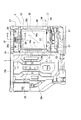
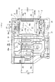
- FIG. 1 is a perspective view showing an embodiment of a vehicle seat and trim cover fixing structure according to the present invention. It is a perspective view which shows the state which pulled out the armrest with the vehicle seat of FIG. It is a perspective view which shows the structure of the back side of the vehicle seat of FIG. It is a top view which shows the flame
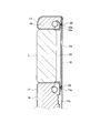
- FIG. 5 is a cross-sectional view taken along line AA in FIG. 4.
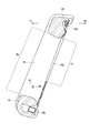
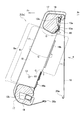
- FIG. 3 is a longitudinal sectional view of a seat back according to the line BB in FIG. 1. It is an enlarged view of the part shown by the arrow C of FIG. It is an enlarged view of the part shown by the arrow D of FIG.
- FIG. 7 is a plan sectional view taken along line EE in FIG.
- FIG. 7 is a cross-sectional view showing the main part of FIG. 6 and a state in which a cushion body is fixed to a frame. It is sectional drawing which shows the state which covered the trim cover on the cushion body of FIG. It is a top view which shows a flame
- FIG. 13 is a cross-sectional view showing a state where a cover board is mounted on the back surface of the seat back in FIG. 12. It is a perspective view showing the whole one embodiment of a cover board.
- FIG. 15B is a cross-sectional view taken along line HH in FIG. 15A.
- FIG. 16B is a cross-sectional view taken along line MM in FIG. 16A.
- FIG. 16B is a cross-sectional view taken along line NN in FIG. 16A. It is an enlarged view of the part shown by the arrow P of FIG. 16A.
- Rear seat (vehicle seat), 1a. 2-seat rear seat, 1b. 1-seat rear seat, 2. Seat back, 2a. 2-seat seat back, 2b. Single seat back, 3. Seat cushion, 3a. 2-seat seat cushion, 3b. Single seat cushion, 6. Recess for armrest storage, 6a. 6. Cushion body recess, Armrest (moving member), 10a, 10b. Frame, 11. Opening, 12a, 12b. Pipe frame, 13. Shaft member, 16. Cushion body, 17. Trim cover, 18. Back carpet, 19a, 19b, 19c. Engagement member (engagement part), 19x. Edge, 20. Yarn, 21. Mounting hole, 22. Hook member (connection member), 23. Cover board (fixing member), 24. Walls, 25a, 25b.
- trim cover fixing structure and vehicle seat according to the present invention First embodiment of trim cover fixing structure and vehicle seat according to the present invention
- a trim cover fixing structure and a vehicle seat according to the present invention will be described based on embodiments.
- the present invention is not limited to this embodiment.
- components may be shown in different ratios from actual ones in order to show characteristic parts in an easy-to-understand manner.
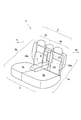
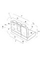
- FIG. 1 and 2 show the appearance of the front side (that is, the passenger compartment side) of the rear seat of an automobile that is an embodiment of the vehicle seat according to the present invention.
- FIG. 1 shows a state in which an armrest, which is a part on which an occupant (not shown) places an elbow, is stored in a predetermined position in a non-use state.
- FIG. 2 shows a state in which the armrest is tilted forward and exposed in use.
- FIG. 3 shows an appearance of the rear seat on the rear side (that is, the luggage compartment side).
- the arrow Fr indicates the front of the vehicle
- the arrow Rr indicates the rear of the vehicle.
- a rear seat as a vehicular seat indicated by reference numeral 1 as a whole has a seat back 2 on which the seat occupant deposits his back and a seat cushion 3 on which the seat occupant rests the buttocks.
- the rear seat 1 includes a seat portion 1a for two people and a seat portion 1b for one seat.
- the area ratio of the seat portion 1a for two seats and the seat portion 1b for one seat is 6: 4.
- the two-seat rear seat 1a includes a two-seat seat back 2a and a two-seat seat cushion 3a.
- the seat 1b for one person includes a seat back 2b for one person and a seat cushion 3b for one person.
- a recess 6 for storing an armrest and an armrest 7 as a moving member are provided at an end portion in the lateral direction of the two-seat seat back 2a (that is, a substantially central portion of the entire seat back 2).
- the armrest 7 is movable between a storage position (see FIG. 1) stored in the storage recess 6 and a use position (see FIG. 2) that is substantially horizontal outside the storage recess 6 (this book). In the embodiment, it can be rotated about a substantially horizontal center line X0).
- a frame 10 a and a frame 10 b are provided inside the seat back 2.
- the frame 10a is a frame corresponding to the two-seat seat back 2a.
- the frame 10b is a frame corresponding to the one-seat seat back 2b.
- These frames 10a and 10b are made of metal, hard synthetic resin, or the like.
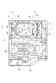
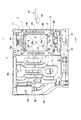
- the frame 10a has a planar structure shown in FIG. 4 and a cross-sectional structure shown in FIG. FIG. 4 shows the frame 10a as viewed from the luggage compartment side (region side in the direction of arrow Rr) of FIG.
- FIG. 5 is a cross-sectional view taken along line AA in FIG.
- the panel 10a is formed in a thin plate shape, that is, a panel shape.
- an opening 11 is formed in a portion on the right side of the center of the frame 10a.
- reference numerals 12a and 12b are pipe frames integrated with the frame 10a.
- Reference numeral 13 denotes a shaft member, which is a shaft member for constituting the rotation center line X0 of FIG.
- the shaft member 13 is provided integrally with the frame 10a.
- FIG. 6 shows a longitudinal sectional view of a substantially central portion (that is, a portion where the armrest 7 is provided) in the left-right direction of the seat back 2 in accordance with the line BB in FIG.
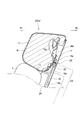
- FIG. 7 is an enlarged view of a portion indicated by an arrow C in FIG. 6 (that is, the top portion of the seat back 2).
- FIG. 8 is an enlarged view of a portion indicated by an arrow D in FIG. 6 (that is, the bottom portion of the seat back 2).
- FIG. 9 is a cross-sectional plan view taken along line EE in FIG.
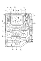
- FIG. 10 shows a state in which the frame 10a (see FIGS. 4 and 5) is viewed from the direction of arrow F in FIG.
- FIG. 10 illustration of various components provided around the frame 10a is omitted for easy understanding of the configuration related to the frame 10a.
- FIG. 10 and FIG. 4 differ in the following points. That is, FIG. 4 shows the frame 10a itself, and FIG. 10 shows a state after a predetermined process is performed on the opening 11 shown in FIG.
- a cushion body 16 is fixed to the front surface of the frame 10a by, for example, adhesion.
- the cushion body 16 is formed of a material having elasticity, for example, a foam molding material.
- the state in which the cushion body 16 is fixed to the frame 10a is as shown in FIG. In FIG. 11, the recess 6a of the cushion body is formed in front of the frame 10a (the direction indicated by the arrow Fr) with the cushion body 16 as a wall.
- the recess 6a of the cushion body is spatially connected to the front area (area in the direction indicated by the arrow Fr) of the cushion body 16. Further, the recess 6a of the cushion body is connected to a rear region (region in the direction indicated by arrow Rr) of the cushion body 16 through an opening 11 provided in the frame 10a.
- the trim cover 17 is formed of leather, synthetic leather, cloth, an equivalent thereof, or a combination thereof.
- a back carpet 18 is stretched on the back of the seat back 2.
- the back carpet 18 is also formed of leather, synthetic leather, cloth or the like. 12 and 13, the trim cover 17 is drawn into the recess 6a of the cushion body 16 from the front (Fr direction) side of the cushion body 16, and further through the opening 11 of the frame 10a. It is pulled out to the rear (Rr direction) side.
- the housing recess 6 is formed by a trim cover 17 covering the cushion body 16.
- the storage recess 6 serves as a recess for storing the armrest 7 (see FIGS. 1 and 2).
- the four corners Z of the trim cover 17 that are pulled out to the back of the opening 11 are sewn together in advance.
- a portion of the trim cover 17 that is pulled out to the back of the opening 11 has a frame-like (rectangular shape in this embodiment) around the opening 11.
- a plurality (three in this embodiment) of hook members 22 as connecting members are sewn in advance on the edge of the lower side portion of the trim cover 17 that is pulled out to the back of the opening 11, or other Attached by technique.
- FIG. 4 a plurality of (three in this embodiment) attachment holes 21 are provided at positions below the opening 11 of the frame 10a.
- the hook member 22 at the lower end of the trim cover 17 is hooked (that is, connected) to the mounting hole 21 of the frame 10a.
- the trim cover 17 is temporarily fixed to the back surface of the frame 10a, and the subsequent processing performed on the trim cover 17 can be easily performed.
- the four corners Z may not be sewn according to circumstances.
- the portion of the trim cover 17 that is pulled out to the back of the opening 11 does not hold the integral frame shape.
- the hook member 22 may not be provided in the trim cover 17, and the attachment hole 21 may not be provided in the frame 10a.
- the engaging members 19a, 19b, 19c (19c is shown in FIG. 13) are preliminarily placed at positions close to the end of the trim cover 17 at the portion pulled out to the rear side (Rr direction) of the cushion body 16. It is fixed.
- the engagement member 19 a is an engagement member disposed at a position above the opening 11.
- the engaging members 19b and 19c are engaging members that are disposed at positions on both the left and right sides of the opening 11, as shown in FIGS.
- the engaging members 19a, 19b, and 19c are formed of, for example, a hard and elastic material such as felt, press felt, nonwoven fabric, or the like.
- the engaging members 19a, 19b, 19c are sewn and fixed to the trim cover 17 by the thread 20 at their substantially central portions as shown in FIGS. Since the engaging members 19a, 19b, and 19c have their substantially central portions fixed to the trim cover 17 by the sewing thread 20, their ends (that is, the long side end) 19x that are parallel to the sewing thread 20 are The sewing thread 20 is supported swingably from the trim cover against its own elastic force around the sewing thread 20.
- a cover board 23 as a fixing member is fitted into the opening 11 of the frame 10a from the rear (arrow Rr direction) side of the seat back 2.
- the cover board 23 is fitted before the rear carpet 18 is connected to the trim cover 17 at the lower end by the first connecting hook 25a and the second connecting hook 25b as connecting members ( That is, it is performed while both hooks 25a and 25b are separated.
- the hooks 25 a and 25 b are connected to each other as shown in FIG. 8, whereby the back carpet 18 is stretched on the back of the seat back 2 as shown in FIG. 6.
- the inside of the seat back 2 is configured not to be visible from the back side (that is, the luggage compartment side).
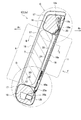
- the cover board 23 has a shape as shown in FIGS. 15A and 15B.
- 15A is a perspective view of the cover board 23 as viewed from the front (arrow Fr direction in FIG. 6) side of FIG.
- FIG. 15B is a longitudinal sectional view taken along line HH in FIG. 15A.
- the cover board 23 is, for example, a synthetic resin molded product.
- the cover board 23 is a plate-like member having a planar extension and at least a peripheral edge 32 of which is plate-like.
- the peripheral edge 32 of the cover board 23 functions as an engaged portion in this embodiment.
- the cover board 23 has a generally rectangular shape and has a frame-like wall 24 protruding forward.
- the cover board 23 has a plurality (two in the embodiment) of protrusions 26 at the lower end thereof, and a plurality of (two in the embodiment) engagement protrusions 28 at the upper end thereof.
- FIG. 4 a plurality (two in this embodiment) of engagement holes 30 are provided above the opening 11 provided in the frame 10a.
- a plurality of (two in this embodiment) positioning holes 27 are provided below the opening 11.
- a hole 36 is provided in advance in a position corresponding to the engagement hole 30 (see FIG. 4) of the frame 10 a in the trim cover 17. Thereby, the engagement hole 30 can be touched through the hole 36.
- a hole 37 is provided in advance in the trim cover 17 at a position corresponding to the positioning hole 27 (see FIG. 4) of the frame 10a. Thereby, the positioning hole 27 can be touched through the hole 37.
- the connecting hook 25a provided at the tip of the back carpet 18 in FIG. 14 is connected to the connecting hook 25b provided at the tip of the trim cover 17 at the bottom.
- the back surface of the seat back 2 is covered with the back carpet 18 as shown in FIG.
- the trim cover 17 is pulled out from the front side to the rear side of the storage recess 6 in FIG. 12, and further, as shown in FIG. , 19c (19c is not shown in FIG. 4), the trim cover 18 can be fixed in a predetermined tension state only by performing an operation of fitting the cover board 23 into the opening 11 while spreading it. That is, according to this embodiment, the fixing structure of the trim cover 17 can be constructed with a simple structure.
- the trim cover 17 since the trim cover 17 is fixed in a state where a preferable tension is applied to the trim cover 17, the trim cover 17 can be firmly fixed.
- a portion of the trim cover 17 that reaches the rear region of the cushion body 16 through the opening 11 has an integrated frame shape around the opening 11. Therefore, the trim cover pulled out to the rear region (that is, the back region) of the opening 11 can maintain a constant shape in a natural state, and the shape does not collapse. For this reason, after the trim cover 17 is pulled out to the rear region of the opening 11, it is very easy to mount the cover board 23 (see FIGS. 10 and 15A) to the opening 11 through the trim cover 17.
- the fixing structure of the trim cover of the present embodiment is very easy to apply to a trunk through structure.
- the trunk through structure is disclosed in, for example, Japanese Patent Application Laid-Open No. 2011-168115 cited as Patent Document 4 in the present specification.
- Japanese Patent Application Laid-Open No. 2011-168115 an opening similar to the opening 11 shown in FIG. 6 of the present application (reference numeral 18 in FIG. 2 of Patent Document 4) and a frame 29 shown in FIG.
- a trunk through structure is constructed using the reference numeral 20 in FIG. 4 and the lid (lid) 31 (reference numeral 16 in FIG. 5 of Patent Document 4) shown in FIG. 17A of the present application.
- the lid 31 has a support shaft 35 at the lower end thereof.
- a shaft storage portion 38 is provided at the lower portion of the frame body 29.
- a frame 29 as shown in FIG. 16A is attached to the back surface of the seat back 2 instead of the cover board 23 in FIG. 6, and the lid of FIG.
- the trunk-through structure can be constructed only by performing an extremely simple process of attaching the opening 31 in an openable and closable manner and providing an opening at the corresponding position of the back carpet 18 in FIG.
- engagement members 19 a, 19 b, 19 c are provided at three positions on the upper side and both left and right sides of the opening 11 provided in the frame 10 a, and the engagement members 19 a, 19 b are formed by the peripheral edges 32 on the three sides of the cover board 23. , 19c.
- an engagement member is provided only at at least one of the four sides of the cover board 23 and is spread by the cover board 23.
- the engaging members 19a, 19b, and 19c are used as the “engaging portion of the trim cover 17”, and the peripheral edge 32 of the cover board 23 is used as the “engaged portion of the cover board 23”.
- a hook or clip fixed to the trim cover may be used as the “engagement portion of the trim cover 17”, and a hole provided in the cover board may be used as the “engaged portion of the cover board 23”. it can.
- a hole provided in the trim cover can be used as the “engagement portion of the trim cover 17”, and a protrusion provided in the cover board can be used as the “engaged portion of the cover board 23”.
- the hook and the clip are parts of any shape that can engage the cover board.
- FIGS. 7 and 10 show the main part of the second embodiment of the trim cover fixing structure and the vehicle seat according to the present invention.
- 18 is a cross-sectional view taken along the line II of FIG. These figures correspond to FIGS. 7 and 10 in the first embodiment, respectively.
- This embodiment is different from the first embodiment shown in FIGS. 7 and 10 in that a step 34 is provided on the peripheral edge 32 of the cover board 33 as a fixing member in FIGS. 18 and 19.
- the engaging members 39a, 39b, and 39c are contained in the thin portion formed by the step 34 (that is, rest on the thin portion).
- the cover board 23 is not provided with a step, so that the engaging members 19 a, 19 b, 19 c mounted on the periphery of the cover board 23 are located behind the seat back 2. It protrudes greatly to the (Rr direction) side. For this reason, when the occupant touches the back carpet 18, there is a possibility that a sense of incongruity that there is a bulge at the engaging members 19a, 19b, 19c may be felt.
- the engaging members 39a, 39b, 39c are accommodated in the thin portion at the level difference 34 and do not protrude greatly outward, Even if the part is touched via 18, there is no sense of incongruity.
- FIG. 20 shows a main part of a trim cover fixing structure and a vehicle seat according to a third embodiment of the present invention.
- the cross-sectional structure taken along line JJ in FIG. 20 is the same as the cross-sectional structure shown in FIG.
- the engaging members 39a, 39b, 39c are accommodated in the thin portion at the step 34 provided on the cover board 43 as a fixing member, as in the embodiment of FIG.
- the entire circumference of the peripheral edge of the cover board 33 is the step 34.
- a step 34 is formed by a step recess or depression 40 partially provided on the periphery of the cover board 43.
- the length L0 of the step recess or recess 40 is set to be slightly longer than the length L1 of the engagement members 39a, 39b, 39c.
- the walls forming the step recesses or depressions 40 can prevent the engaging members 39a, 39b, 39c from moving relative to the cover board 43.
- the engaging members 39 a, 39 b, 39 c move relative to the cover board 33 and the trim cover 17 could occur.
- the engagement members 39a, 39b, and 39c are prevented from being displaced due to the action of the wall forming the step recess or depression 40. Thereby, it is possible to prevent wrinkles from occurring in the trim cover 17.
- FIG. 21 shows a main part of a trim cover fixing structure and a vehicle seat according to a fourth embodiment of the present invention. This main part corresponds to the part shown in FIG. 10 in the first embodiment.
- the present embodiment shown in FIG. 21 is different from the previous embodiment shown in FIG. 10 as compared with the engaging members 19b and 19c on the left and right side portions of the trim cover 17, as shown in FIG.
- the opening hole 45 is provided in the outer portion in advance.
- the step 34 is provided on the peripheral edge 32 of the cover board 33 as a fixing member. Also for this embodiment, an opening hole 45 as shown in FIG. 21 can be provided. In that case, the structure is as shown in FIG.
- the step 34 is formed by providing a step recess or depression 40 on the peripheral edge 32 of the cover board 43. Also for this embodiment, an opening hole 45 as shown in FIG. 21 can be provided. In that case, the structure is as shown in FIG.
- the present invention is applied to the fixing structure of the trim cover at the storage recess 6 for storing the armrest 7 of the seat back 2 in FIG. 2, for example.
- the present invention can also be applied to the trim cover fixing structure other than the concave portion for use.
- the present invention can also be applied to a trim cover fixing structure other than the seat back 2 of the vehicle seat 1.
Landscapes
- Engineering & Computer Science (AREA)
- Aviation & Aerospace Engineering (AREA)
- Transportation (AREA)
- Mechanical Engineering (AREA)
- Textile Engineering (AREA)
- Seats For Vehicles (AREA)
Abstract
Description
(1) トリムカバーの端部近傍に設けられた係合部に固定部材(例えばカバーボード)の被係合部を押し付け、さらに固定部材によって係合部を押しやってトリムカバーを引っ張ることにより、当該トリムカバーをクッション体に対して固定することができる。このように、固定部材によって係合部を押しやるだけという作用によってトリムカバーを固定できるので、トリムカバーの固定構造を非常に簡単に構築できる。
以下、本発明に係るトリムカバーの固定構造及び車両用シートを実施形態に基づいて説明する。なお、本発明がこの実施形態に限定されないことはもちろんである。また、本明細書に添付した図面では特徴的な部分を分かり易く示すために実際のものとは異なった比率で構成要素を示す場合がある。
図1及び図2は、本発明に係る車両用シートの一実施形態である自動車のリヤシートの前方側(すなわち乗員室側)の外観を示している。図1は、着座者(図示せず)が肘を置く部品であるアームレストが非使用状態で所定位置に収納されている状態を示している。図2は、アームレストが使用状態で前方へ倒されて露出している状態を示している。図3はこのリヤシートの後方側(すなわち荷物室側)の外観を示している。これらの図において、矢印Frが車両の前方を示しており、矢印Rrが車両の後方を示している。
図6は図1のB-B線に従ってシートバック2の左右方向における略中央部分(すなわち、アームレスト7が設けられている部分)の縦断面図を示している。図7は、図6における矢印Cで示す部分(すなわちシートバック2の頂部)の拡大図である。図8は、図6における矢印Dで示す部分(すなわちシートバック2の底部)の拡大図である。図9は、図6におけるE-E線に従った平面断面図である。
カバーボード23は図15A及び図15Bに示すような形状を有している。図15Aはカバーボード23を図6の前方(図6の矢印Fr方向)側から見た状態の斜視図である。図15Bは、図15AにおけるH-H線に従った縦断面図である。カバーボード23は、例えば合成樹脂の成形品である。
本実施形態のトリムカバーの固定構造は、トランクスルー構造への適用が非常に容易である。トランクスルー構造は、例えば、本願明細書において特許文献4として挙げている特開2011-168115号公報に開示されている。特開2011-168115号公報では、本願の図6で示した開口11と同様の開口(特許文献4の図2の符号18)と、本願の図16Aに示した枠体29(特許文献4の図4の符号20)と、本願の図17Aに示したリッド(蓋)31(特許文献4の図5の符号16)とを用いてトランクスルー構造を構築している。
(1) 図10では、フレーム10aに設けた開口11の上側及び左右両側の3ヶ所に係合部材19a,19b,19cを設け、カバーボード23の3辺の周縁32によって係合部材19a,19b,19cを押し広げる構成とした。しかしながら、これに代えて、カバーボード23の4辺のうちの少なくとも1ヶ所だけに係合部材を設けてこれをカバーボード23によって押し広げるという構成を採用できる。
図18及び図19は、本発明に係るトリムカバーの固定構造及び車両用シートの第2の実施形態の主要部を示している。図18は図19のI-I線に従った断面図である。これらの図は、それぞれ、第1の実施形態における図7及び図10に相当している。
図20は、本発明に係るトリムカバーの固定構造及び車両用シートの第3の実施形態の主要部を示している。図20におけるJ-J線に従った断面構造は図18に示した断面構造と同じである。
図21は、本発明に係るトリムカバーの固定構造及び車両用シートの第4の実施形態の主要部を示している。この主要部は第1の実施形態において図10に示した部分に対応している。図21に示した本実施形態が図10に示した先の実施形態と異なっている点は、図21に示すように、トリムカバー17の左右の側辺部の係合部材19b及び19cよりも外側部分に開き用孔45を予め設けたことである。
以上、好ましい実施形態を挙げて本発明を説明したが、本発明はその実施形態に限定されるものでなく、請求の範囲に記載した発明の範囲内で種々に改変できる。
Claims (16)
- 弾力性を有したクッション体と、
当該クッション体を覆うトリムカバーと
を有した車両用シートに用いられるトリムカバーの固定構造であって、
前記トリムカバーの端部近傍に固定された係合部と、
前記クッション体を覆った状態の前記トリムカバー上に在る前記係合部に係合する被係合部を備えた固定部材と、を有しており、
前記固定部材は前記係合部に係合することにより前記クッション体を覆っている前記トリムカバーに張力を付与することができ、この張力付与状態で前記トリムカバーが前記クッション体の表面に固定される
ことを特徴とする車両用シートのトリムカバーの固定構造。 - 前記固定部材は、平面的に広がりをもっていて少なくともその周縁が板状である板状部材であり、その板状部材の周縁が前記係合部に係合することを特徴とする請求項1記載のトリムカバーの固定構造。
- 前記固定部材の周縁は前記係合部と前記トリムカバーとの間に挿入された状態で前記係合部に係合することを特徴とする請求項2記載のトリムカバーの固定構造。
- 前記固定部材は、前記係合部と前記トリムカバーとの間に挿入される部分に段差を有しており、この段差によって形成された肉薄部に前記係合部が入ることを特徴とする請求項3記載のトリムカバーの固定構造。
- 前記段差は前記固定部材の周縁に設けた段差用凹部によって形成されており、当該段差用凹部を形成している壁は前記係合部が前記固定部材に対して相対移動することを規制することを特徴とする請求項4記載のトリムカバーの固定構造。
- 前記係合部は前記トリムカバーに縫い付けられていることを特徴とする請求項1から請求項5のいずれか1つに記載のトリムカバーの固定構造。
- 前記係合部は長辺及び短辺を有した細長い帯状部材であり、当該帯状部材の長辺が前記固定部材に係合することを特徴とする請求項1から請求項6のいずれか1つに記載のトリムカバーの固定構造。
- 前記係合部はフェルト、プレスフェルト又は不織布によって形成されていることを特徴とする請求項1から請求項7のいずれか1つに記載のトリムカバーの固定構造。
- 前記クッション体を覆っている前記トリムカバーを壁として形成された収納用凹部であって前記クッション体の前方領域と前記クッション体の後方領域とをつなぐ開口を備えている収納用凹部と、
当該収納用凹部に収納される位置と当該収納用凹部の外側へ出る位置との間で移動可能な移動部材と、を有しており、
前記トリムカバーは、前記クッション体の前側領域から前記収納用凹部及び前記開口を通って前記クッション体の後方領域へ達するように設けられており、
前記係合部は前記クッション体の後方領域へ達する部分の前記トリムカバー上に固定されており、
前記固定部材は前記クッション体の後方側から前記収納用凹部の開口を塞ぐためのカバーボードであり、
当該カバーボードが前記収納用凹部の開口を塞ぐ位置に配置されたときに当該カバーボードの周縁が前記係合部に係合する
ことを特徴とする請求項1から請求項8のいずれか1つに記載のトリムカバーの固定構造。 - 前記係合部は、前記収納用凹部に備えられた前記開口の少なくとも左右両側で前記クッション体の後方領域へ達する部分の前記トリムカバー上に固定されており、
固定部材としての前記カバーボードは左右両側の周縁において前記それぞれの係合部に係合して前記トリムカバーに張力を付与する
ことを特徴とする請求項9記載のトリムカバーの固定構造。 - 前記移動部材はアームレスト及び/又はサイドテーブルであることを特徴とする請求項9又は請求項10記載のトリムカバーの固定構造。
- 弾力性を有したクッション体と、
当該クッション体を覆うトリムカバーと、
前記クッション体の前方領域と前記クッション体の後方領域とをつなぐ開口と、
を有した車両用シートに用いられるトリムカバーの固定構造であって、
前記トリムカバーは、前記クッション体の前側領域から前記開口を通って前記クッション体の後方領域へ達するように設けられており、
前記クッション体の後方領域へ達している前記トリムカバーの端部近傍に係合部が設けられており、
前記開口を前記クッション体の後方側から塞ぐためのカバーボードが設けられており、
当該カバーボードには被係合部が設けられており、
当該カバーボードが前記開口を塞ぐ位置に配置されたときに前記被係合部が前記係合部に係合することにより前記クッション体を覆っている前記トリムカバーに張力が付与され、この張力付与状態で前記トリムカバーが前記クッション体の表面に固定されており、
前記トリムカバーのうちの前記開口を通って前記クッション体の後方領域へ達している部分は前記開口の周囲で一体な枠形状になっている
ことを特徴とするトリムカバーの固定構造。 - 前記トリムカバーのうちの前記開口を通って前記クッション体の後方領域へ達している部分は互いに縫い合わされて前記開口の周囲で一体な枠形状になっていることを特徴とする請求項12記載のトリムカバーの固定構造。
- 前記クッション体はフレームによって支持されており、
前記トリムカバーのうち前記開口を通って前記クッション体の後方領域へ達している部分に接続部材が設けられており、
当該接続部材は前記フレームに接続されている
ことを特徴とする請求項12又は請求項13記載のトリムカバーの固定構造。 - 前記トリムカバーのうちの前記開口を通って前記クッション体の後方領域へ達している部分において前記係合部よりも外側の部分に、開き用孔が設けられていることを特徴とする請求項12から請求項14のいずれか1つに記載のトリムカバーの固定構造。
- 弾力性を有したクッション体と、当該クッション体を覆うトリムカバーと、当該トリムカバーを前記クッション体に対して固定するトリムカバーの固定構造とを有した車両用シートにおいて、前記トリムカバーの固定構造は請求項1から請求項15のいずれか1つに記載したトリムカバーの固定構造であることを特徴とする車両用シート。
Priority Applications (4)
| Application Number | Priority Date | Filing Date | Title |
|---|---|---|---|
| JP2015501302A JP5959081B2 (ja) | 2013-02-22 | 2013-12-26 | 車両用シートのトリムカバーの固定構造及び車両用シート |
| EP13875346.2A EP2960202B1 (en) | 2013-02-22 | 2013-12-26 | Trim cover affixation structure for vehicle seat, and vehicle seat |
| US14/758,481 US9902304B2 (en) | 2013-02-22 | 2013-12-26 | Vehicle seat trim cover fixing structure and vehicle seat |
| AU2013378970A AU2013378970B2 (en) | 2013-02-22 | 2013-12-26 | Trim cover affixation structure for vehicle seat, and vehicle seat |
Applications Claiming Priority (4)
| Application Number | Priority Date | Filing Date | Title |
|---|---|---|---|
| JP2013-033442 | 2013-02-22 | ||
| JP2013033442 | 2013-02-22 | ||
| JP2013151486 | 2013-07-22 | ||
| JP2013-151486 | 2013-07-22 |
Publications (1)
| Publication Number | Publication Date |
|---|---|
| WO2014129087A1 true WO2014129087A1 (ja) | 2014-08-28 |
Family
ID=51390898
Family Applications (1)
| Application Number | Title | Priority Date | Filing Date |
|---|---|---|---|
| PCT/JP2013/084870 Ceased WO2014129087A1 (ja) | 2013-02-22 | 2013-12-26 | 車両用シートのトリムカバーの固定構造及び車両用シート |
Country Status (5)
| Country | Link |
|---|---|
| US (1) | US9902304B2 (ja) |
| EP (1) | EP2960202B1 (ja) |
| JP (1) | JP5959081B2 (ja) |
| AU (1) | AU2013378970B2 (ja) |
| WO (1) | WO2014129087A1 (ja) |
Families Citing this family (9)
| Publication number | Priority date | Publication date | Assignee | Title |
|---|---|---|---|---|
| US9643524B2 (en) * | 2006-09-05 | 2017-05-09 | Faurecia Autositze Gmbh | Backrest for a rear seat of a motor vehicle |
| JP6387258B2 (ja) * | 2014-07-10 | 2018-09-05 | 日本発條株式会社 | シートバックフレーム及び車両用シート |
| USD768412S1 (en) | 2016-03-01 | 2016-10-11 | Vu Phan Quang Ngo | Car seat protector |
| JP6572801B2 (ja) | 2016-03-03 | 2019-09-11 | テイ・エス テック株式会社 | 車両用シート |
| JP6245300B2 (ja) * | 2016-04-28 | 2017-12-13 | マツダ株式会社 | シートバック構造 |
| JP6834410B2 (ja) * | 2016-11-29 | 2021-02-24 | トヨタ紡織株式会社 | 乗物用シート |
| GB2567259B (en) * | 2017-10-09 | 2020-04-08 | Jaguar Land Rover Ltd | Control of an armrest of a vehicle seating arrangement |
| GB2604879B (en) * | 2021-03-16 | 2023-06-14 | Jaguar Land Rover Ltd | Apparatus for use with a vehicle armrest |
| JP7618490B2 (ja) * | 2021-04-19 | 2025-01-21 | 日本発條株式会社 | 車両用シート構造、パッド材成形方法、及び車両用シート製造方法 |
Citations (6)
| Publication number | Priority date | Publication date | Assignee | Title |
|---|---|---|---|---|
| JPH04107696U (ja) | 1991-02-27 | 1992-09-17 | 株式会社タチエス | 乗り物シート |
| JPH0711655U (ja) | 1993-07-30 | 1995-02-21 | ナショナル住宅産業株式会社 | 床パネル仮置治具 |
| JP2000184940A (ja) * | 1998-12-21 | 2000-07-04 | Tachi S Co Ltd | 裏面カバー付きシートのトリムカバー端末係止構造 |
| JP2003071160A (ja) | 2001-08-30 | 2003-03-11 | T S Tec Kk | 車両用シートの表皮材端末固定構造 |
| JP2003071163A (ja) * | 2001-08-31 | 2003-03-11 | T S Tec Kk | 車両用シートの表皮材端末固定構造 |
| JP2011168115A (ja) | 2010-02-17 | 2011-09-01 | Tachi S Co Ltd | トランクスルー構造の車両用シート |
Family Cites Families (18)
| Publication number | Priority date | Publication date | Assignee | Title |
|---|---|---|---|---|
| JP3001800B2 (ja) * | 1994-12-12 | 2000-01-24 | 本田技研工業株式会社 | 車両の開閉体 |
| DE3615262A1 (de) * | 1986-05-06 | 1987-11-12 | Opel Adam Ag | Rueckenlehne fuer fahrzeugsitze, insbesondere fuer hintersitze von kraftfahrzeugen |
| US4786103A (en) * | 1988-03-21 | 1988-11-22 | Hoover Universal, Inc. | Vehicle seat trim assembly |
| JPH0378454U (ja) * | 1989-11-29 | 1991-08-08 | ||
| JPH0711655Y2 (ja) | 1990-06-01 | 1995-03-22 | 株式会社タチエス | 自動車用シートにおけるアームレスト格納部の構造 |
| US5401075A (en) * | 1994-02-09 | 1995-03-28 | Hoover Universal, Inc. | Closure for a seat trim cover |
| US5628543A (en) * | 1995-09-27 | 1997-05-13 | Hoover Universal, Inc. | Vehicle seat back having ski tote bag and trunk pass through |
| US5662377A (en) * | 1995-10-18 | 1997-09-02 | Magna Lomason Corporation | Vehicle seat interlock system |
| US5752739A (en) * | 1996-09-30 | 1998-05-19 | Tachi-S Co., Ltd. | Mounting for an armrest in seat |
| US6073996A (en) * | 1997-12-31 | 2000-06-13 | Tachi-S Co., Ltd. | Structure of seat back with armrest and method for forming the same |
| DE50109200D1 (de) * | 2000-08-30 | 2006-05-11 | Bos Gmbh | Transportbehälter-Einrichtung für Fahrzeuge, wie z.B. Durchladeeinrichtung |
| DE10113619C2 (de) * | 2001-03-20 | 2003-03-06 | Butz Peter Verwaltung | Transportbehälter-Einrichtung für den Einbau in Kraftfahrzeuge, wie z.B. Durchladeinrichtung |
| JP3897298B2 (ja) * | 2002-11-27 | 2007-03-22 | 株式会社タチエス | リア・シート・アームレスト |
| DE102004050272A1 (de) * | 2004-10-14 | 2006-04-20 | Bos Gmbh & Co. Kg | Verstärkter Skisack |
| US7152899B2 (en) * | 2005-02-03 | 2006-12-26 | Toyota Technical Center Usa, Inc. | Automotive trunk pass-through for reclining rear seat |
| US7611184B1 (en) * | 2008-07-03 | 2009-11-03 | Ts Tech Co., Ltd. | Vehicular trunk-through openable and closable device |
| US8157322B2 (en) * | 2008-12-22 | 2012-04-17 | Toyota Motor Engineering & Manufacturing North America, Inc. | Seat back assembly with low density frame |
| US7731293B1 (en) * | 2008-12-22 | 2010-06-08 | Toyota Motor Engineering & Manufacturing North America, Inc. | Multiple part resin seat back with integrated adjustable headrest support |
-
2013
- 2013-12-26 US US14/758,481 patent/US9902304B2/en active Active
- 2013-12-26 EP EP13875346.2A patent/EP2960202B1/en active Active
- 2013-12-26 WO PCT/JP2013/084870 patent/WO2014129087A1/ja not_active Ceased
- 2013-12-26 JP JP2015501302A patent/JP5959081B2/ja active Active
- 2013-12-26 AU AU2013378970A patent/AU2013378970B2/en not_active Ceased
Patent Citations (6)
| Publication number | Priority date | Publication date | Assignee | Title |
|---|---|---|---|---|
| JPH04107696U (ja) | 1991-02-27 | 1992-09-17 | 株式会社タチエス | 乗り物シート |
| JPH0711655U (ja) | 1993-07-30 | 1995-02-21 | ナショナル住宅産業株式会社 | 床パネル仮置治具 |
| JP2000184940A (ja) * | 1998-12-21 | 2000-07-04 | Tachi S Co Ltd | 裏面カバー付きシートのトリムカバー端末係止構造 |
| JP2003071160A (ja) | 2001-08-30 | 2003-03-11 | T S Tec Kk | 車両用シートの表皮材端末固定構造 |
| JP2003071163A (ja) * | 2001-08-31 | 2003-03-11 | T S Tec Kk | 車両用シートの表皮材端末固定構造 |
| JP2011168115A (ja) | 2010-02-17 | 2011-09-01 | Tachi S Co Ltd | トランクスルー構造の車両用シート |
Also Published As
| Publication number | Publication date |
|---|---|
| AU2013378970B2 (en) | 2016-07-07 |
| JPWO2014129087A1 (ja) | 2017-02-02 |
| JP5959081B2 (ja) | 2016-08-02 |
| US20150336489A1 (en) | 2015-11-26 |
| AU2013378970A1 (en) | 2015-07-09 |
| EP2960202B1 (en) | 2021-02-17 |
| US9902304B2 (en) | 2018-02-27 |
| EP2960202A4 (en) | 2016-10-26 |
| EP2960202A1 (en) | 2015-12-30 |
Similar Documents
| Publication | Publication Date | Title |
|---|---|---|
| JP5959081B2 (ja) | 車両用シートのトリムカバーの固定構造及び車両用シート | |
| JP5911894B2 (ja) | 車両室内収納ポケット | |
| KR101045734B1 (ko) | 시트 커버용 소프트 커버 | |
| CN204452140U (zh) | 交通工具用座椅 | |
| JP5245367B2 (ja) | 着せ替えシートカバーのシート被覆構造 | |
| CN104640740B (zh) | 车辆用座椅 | |
| JP5822183B2 (ja) | バックル収納構造 | |
| US9440568B2 (en) | Seat for vehicle | |
| JP5607375B2 (ja) | 内装部品およびコンソールボックス | |
| US20160325658A1 (en) | ISOFIX Trim Retainer | |
| JP2008272134A (ja) | シートバック構造 | |
| US10293762B2 (en) | Vehicular interior component, vehicular interior panel, and vehicular composite interior component | |
| CN105813891A (zh) | 具有用于座椅靠背框架的结构覆盖物的车辆座椅 | |
| US20180022245A1 (en) | Vehicle seat | |
| JP2013220761A (ja) | 内装部品および内装部品製造用作業工具 | |
| JP2012030755A (ja) | 車両用シートのための小物入れ構造および車両用シートへの小物入れ取付け方法 | |
| US10369910B1 (en) | Aesthetic seat backrest panel for a motor vehicle | |
| US10358064B2 (en) | Headrest cover | |
| WO2013114456A1 (ja) | 車両用シートのための小物入れ構造および車両用シートへの小物入れ取付け方法 | |
| CN103241183B (zh) | 车辆座椅用的小件物品容器结构及小件物品容器向车辆座椅上的安装方法 | |
| JP2013043599A (ja) | 内装部品 | |
| JP6974136B2 (ja) | 乗物用シート | |
| JP2010012093A (ja) | シートバック構造 | |
| JP7618490B2 (ja) | 車両用シート構造、パッド材成形方法、及び車両用シート製造方法 | |
| JP2019189008A (ja) | シートカバー |
Legal Events
| Date | Code | Title | Description |
|---|---|---|---|
| 121 | Ep: the epo has been informed by wipo that ep was designated in this application |
Ref document number: 13875346 Country of ref document: EP Kind code of ref document: A1 |
|
| ENP | Entry into the national phase |
Ref document number: 2015501302 Country of ref document: JP Kind code of ref document: A |
|
| WWE | Wipo information: entry into national phase |
Ref document number: 14758481 Country of ref document: US |
|
| ENP | Entry into the national phase |
Ref document number: 2013378970 Country of ref document: AU Date of ref document: 20131226 Kind code of ref document: A |
|
| WWE | Wipo information: entry into national phase |
Ref document number: 2013875346 Country of ref document: EP |
|
| NENP | Non-entry into the national phase |
Ref country code: DE |