WO2014129094A1 - Dispositif de sertissage de fil et procédé de sertissage de fil - Google Patents
Dispositif de sertissage de fil et procédé de sertissage de fil Download PDFInfo
- Publication number
- WO2014129094A1 WO2014129094A1 PCT/JP2013/085282 JP2013085282W WO2014129094A1 WO 2014129094 A1 WO2014129094 A1 WO 2014129094A1 JP 2013085282 W JP2013085282 W JP 2013085282W WO 2014129094 A1 WO2014129094 A1 WO 2014129094A1
- Authority
- WO
- WIPO (PCT)
- Prior art keywords
- crimping
- wire
- guide
- electric wire
- tip
- Prior art date
- Legal status (The legal status is an assumption and is not a legal conclusion. Google has not performed a legal analysis and makes no representation as to the accuracy of the status listed.)
- Ceased
Links
Images


Classifications
-
- H—ELECTRICITY
- H01—ELECTRIC ELEMENTS
- H01R—ELECTRICALLY-CONDUCTIVE CONNECTIONS; STRUCTURAL ASSOCIATIONS OF A PLURALITY OF MUTUALLY-INSULATED ELECTRICAL CONNECTING ELEMENTS; COUPLING DEVICES; CURRENT COLLECTORS
- H01R43/00—Apparatus or processes specially adapted for manufacturing, assembling, maintaining, or repairing of line connectors or current collectors or for joining electric conductors
- H01R43/04—Apparatus or processes specially adapted for manufacturing, assembling, maintaining, or repairing of line connectors or current collectors or for joining electric conductors for forming connections by deformation, e.g. crimping tool
- H01R43/048—Crimping apparatus or processes
- H01R43/052—Crimping apparatus or processes with wire-feeding mechanism
-
- H—ELECTRICITY
- H01—ELECTRIC ELEMENTS
- H01R—ELECTRICALLY-CONDUCTIVE CONNECTIONS; STRUCTURAL ASSOCIATIONS OF A PLURALITY OF MUTUALLY-INSULATED ELECTRICAL CONNECTING ELEMENTS; COUPLING DEVICES; CURRENT COLLECTORS
- H01R4/00—Electrically-conductive connections between two or more conductive members in direct contact, i.e. touching one another; Means for effecting or maintaining such contact; Electrically-conductive connections having two or more spaced connecting locations for conductors and using contact members penetrating insulation
- H01R4/10—Electrically-conductive connections between two or more conductive members in direct contact, i.e. touching one another; Means for effecting or maintaining such contact; Electrically-conductive connections having two or more spaced connecting locations for conductors and using contact members penetrating insulation effected solely by twisting, wrapping, bending, crimping, or other permanent deformation
- H01R4/18—Electrically-conductive connections between two or more conductive members in direct contact, i.e. touching one another; Means for effecting or maintaining such contact; Electrically-conductive connections having two or more spaced connecting locations for conductors and using contact members penetrating insulation effected solely by twisting, wrapping, bending, crimping, or other permanent deformation by crimping
- H01R4/20—Electrically-conductive connections between two or more conductive members in direct contact, i.e. touching one another; Means for effecting or maintaining such contact; Electrically-conductive connections having two or more spaced connecting locations for conductors and using contact members penetrating insulation effected solely by twisting, wrapping, bending, crimping, or other permanent deformation by crimping using a crimping sleeve
-
- H—ELECTRICITY
- H01—ELECTRIC ELEMENTS
- H01R—ELECTRICALLY-CONDUCTIVE CONNECTIONS; STRUCTURAL ASSOCIATIONS OF A PLURALITY OF MUTUALLY-INSULATED ELECTRICAL CONNECTING ELEMENTS; COUPLING DEVICES; CURRENT COLLECTORS
- H01R13/00—Details of coupling devices of the kinds covered by groups H01R12/70 or H01R24/00 - H01R33/00
- H01R13/02—Contact members
- H01R13/10—Sockets for co-operation with pins or blades
- H01R13/11—Resilient sockets
- H01R13/113—Resilient sockets co-operating with pins or blades having a rectangular transverse section
-
- H—ELECTRICITY
- H01—ELECTRIC ELEMENTS
- H01R—ELECTRICALLY-CONDUCTIVE CONNECTIONS; STRUCTURAL ASSOCIATIONS OF A PLURALITY OF MUTUALLY-INSULATED ELECTRICAL CONNECTING ELEMENTS; COUPLING DEVICES; CURRENT COLLECTORS
- H01R4/00—Electrically-conductive connections between two or more conductive members in direct contact, i.e. touching one another; Means for effecting or maintaining such contact; Electrically-conductive connections having two or more spaced connecting locations for conductors and using contact members penetrating insulation
- H01R4/58—Electrically-conductive connections between two or more conductive members in direct contact, i.e. touching one another; Means for effecting or maintaining such contact; Electrically-conductive connections having two or more spaced connecting locations for conductors and using contact members penetrating insulation characterised by the form or material of the contacting members
- H01R4/62—Connections between conductors of different materials; Connections between or with aluminium or steel-core aluminium conductors
-
- H—ELECTRICITY
- H01—ELECTRIC ELEMENTS
- H01R—ELECTRICALLY-CONDUCTIVE CONNECTIONS; STRUCTURAL ASSOCIATIONS OF A PLURALITY OF MUTUALLY-INSULATED ELECTRICAL CONNECTING ELEMENTS; COUPLING DEVICES; CURRENT COLLECTORS
- H01R43/00—Apparatus or processes specially adapted for manufacturing, assembling, maintaining, or repairing of line connectors or current collectors or for joining electric conductors
- H01R43/04—Apparatus or processes specially adapted for manufacturing, assembling, maintaining, or repairing of line connectors or current collectors or for joining electric conductors for forming connections by deformation, e.g. crimping tool
- H01R43/048—Crimping apparatus or processes
- H01R43/05—Crimping apparatus or processes with wire-insulation stripping
-
- H—ELECTRICITY
- H01—ELECTRIC ELEMENTS
- H01R—ELECTRICALLY-CONDUCTIVE CONNECTIONS; STRUCTURAL ASSOCIATIONS OF A PLURALITY OF MUTUALLY-INSULATED ELECTRICAL CONNECTING ELEMENTS; COUPLING DEVICES; CURRENT COLLECTORS
- H01R43/00—Apparatus or processes specially adapted for manufacturing, assembling, maintaining, or repairing of line connectors or current collectors or for joining electric conductors
- H01R43/04—Apparatus or processes specially adapted for manufacturing, assembling, maintaining, or repairing of line connectors or current collectors or for joining electric conductors for forming connections by deformation, e.g. crimping tool
- H01R43/048—Crimping apparatus or processes
- H01R43/055—Crimping apparatus or processes with contact member feeding mechanism
-
- Y—GENERAL TAGGING OF NEW TECHNOLOGICAL DEVELOPMENTS; GENERAL TAGGING OF CROSS-SECTIONAL TECHNOLOGIES SPANNING OVER SEVERAL SECTIONS OF THE IPC; TECHNICAL SUBJECTS COVERED BY FORMER USPC CROSS-REFERENCE ART COLLECTIONS [XRACs] AND DIGESTS
- Y10—TECHNICAL SUBJECTS COVERED BY FORMER USPC
- Y10T—TECHNICAL SUBJECTS COVERED BY FORMER US CLASSIFICATION
- Y10T29/00—Metal working
- Y10T29/49—Method of mechanical manufacture
- Y10T29/49002—Electrical device making
- Y10T29/49117—Conductor or circuit manufacturing
- Y10T29/49174—Assembling terminal to elongated conductor
- Y10T29/49181—Assembling terminal to elongated conductor by deforming
- Y10T29/49185—Assembling terminal to elongated conductor by deforming of terminal
- Y10T29/49192—Assembling terminal to elongated conductor by deforming of terminal with insulation removal
-
- Y—GENERAL TAGGING OF NEW TECHNOLOGICAL DEVELOPMENTS; GENERAL TAGGING OF CROSS-SECTIONAL TECHNOLOGIES SPANNING OVER SEVERAL SECTIONS OF THE IPC; TECHNICAL SUBJECTS COVERED BY FORMER USPC CROSS-REFERENCE ART COLLECTIONS [XRACs] AND DIGESTS
- Y10—TECHNICAL SUBJECTS COVERED BY FORMER USPC
- Y10T—TECHNICAL SUBJECTS COVERED BY FORMER US CLASSIFICATION
- Y10T29/00—Metal working
- Y10T29/49—Method of mechanical manufacture
- Y10T29/49002—Electrical device making
- Y10T29/49117—Conductor or circuit manufacturing
- Y10T29/49204—Contact or terminal manufacturing
- Y10T29/49208—Contact or terminal manufacturing by assembling plural parts
- Y10T29/4922—Contact or terminal manufacturing by assembling plural parts with molding of insulation
-
- Y—GENERAL TAGGING OF NEW TECHNOLOGICAL DEVELOPMENTS; GENERAL TAGGING OF CROSS-SECTIONAL TECHNOLOGIES SPANNING OVER SEVERAL SECTIONS OF THE IPC; TECHNICAL SUBJECTS COVERED BY FORMER USPC CROSS-REFERENCE ART COLLECTIONS [XRACs] AND DIGESTS
- Y10—TECHNICAL SUBJECTS COVERED BY FORMER USPC
- Y10T—TECHNICAL SUBJECTS COVERED BY FORMER US CLASSIFICATION
- Y10T29/00—Metal working
- Y10T29/53—Means to assemble or disassemble
- Y10T29/5313—Means to assemble electrical device
- Y10T29/532—Conductor
- Y10T29/53209—Terminal or connector
- Y10T29/53213—Assembled to wire-type conductor
- Y10T29/53235—Means to fasten by deformation
Definitions
- a terminal fitting in a terminal connection band constituted by a carrier formed in a strip shape and a plurality of terminal fittings protruding from at least one end side in the width direction of the carrier is peeled off from the insulating coating on the tip end side of the covered electric wire.
- the present invention relates to a wire crimping apparatus and a wire crimping method for crimping and connecting to a tip portion of an electric wire exposing a conductor.
- an open barrel type crimping terminal provided with a barrel piece that crimps a wire tip part in which the insulation coating on the tip side of the coated electric wire is peeled off in a form that is bent from both sides in the width direction and opposed to the middle part
- a closed barrel type crimp terminal having a crimp portion formed into a hollow shape into which an electric wire distal end portion can be inserted from an insertion opening opened on the proximal end side is used.
- the closed barrel type crimp terminal is formed in a hollow shape, the tip of the electric wire inserted inside can be covered without gaps in the entire circumferential direction, so that the crimp terminal and the conductor of the covered electric wire can be securely connected. It is considered that corrosion that occurs on the surface of the crimping portion or the conductor surface at the crimping connection portion can be prevented.
- such a crimp terminal is arranged by using a wire crimping device such as a terminal crimping device disclosed in Patent Document 1 after arranging the wire tip portion of the covered wire in the crimp portion of the crimp terminal.
- a wire crimping device such as a terminal crimping device disclosed in Patent Document 1 after arranging the wire tip portion of the covered wire in the crimp portion of the crimp terminal.
- the present invention provides an electric wire crimping apparatus and an electric wire crimping method capable of securely and efficiently crimping a wire tip portion with respect to a hollow crimp portion of a closed barrel type crimp terminal.
- the purpose is to do.
- the present invention provides a coated electric wire provided with a wire tip portion in which a conductor is covered with an insulating coating, and the insulating coating on the tip side is peeled to expose the conductor, and a hollow shape that allows crimp connection of the wire tip portion.
- a wire crimping device for connecting a closed barrel type crimp terminal provided with a crimping part by crimping the crimping part and the electrical tip part, and an electric wire opened on the proximal end side in the terminal axial direction of the crimping part
- a crimping means for crimping the crimping portion with the wire tip inserted inside from the insertion port; and the wire tip to the wire insertion port of the crimping terminal arranged at a predetermined position for crimping by the crimping means.
- a guide means for guiding wherein an inner diameter of a portion of the guide means facing the electric wire insertion port is formed in accordance with an inner diameter of the electric wire insertion port.
- the conductor can be a stranded wire or a single wire obtained by twisting a strand, and further, for example, constitutes a copper-based conductor or a crimp terminal composed of a metal similar to a crimp terminal composed of copper or a copper alloy.
- An aluminum-based conductor composed of a dissimilar metal such as aluminum or an aluminum alloy, which is a base metal, can be used.
- the conductor may be a heterogeneous mixed line in which an aluminum based conductor is disposed around a copper based conductor, or may be a heterogeneous mixed line in which a copper based conductor is disposed around an aluminum based conductor.
- the hollow crimping portion described above is a cylindrical or rectangular tubular crimping portion, or a crimping portion having a cylindrical or rectangular tubular shape in which the end opposite to the wire insertion port is sealed. Can do.
- the guide means may be a separate member that is different from a part of the mechanism of the apparatus, a crimp terminal, or a covered electric wire.
- the tip end of the electric wire can be smoothly inserted into the hollow crimp portion of the closed barrel type crimp terminal.
- the tip of the wire is guided by the guide unit with respect to the wire insertion port of the crimping unit to be crimped by the crimping unit, and the tip of the wire is smoothly inserted into the crimping unit. can do. Therefore, from the viewpoint of water-stopping, even if the inner diameter before crimping is the same as the outer diameter of the covered wire and the inner diameter of the crimping portion, the tip of the wire is smoothly inserted and crimped. can do.
- the wire tip can be smoothly inserted into the hollow crimp portion of the closed barrel type crimp terminal, and the crimp can be reliably and efficiently performed.
- the guide means can be configured in a shape in which the inner diameter gradually increases toward the base end side in the terminal axis direction.
- the shape in which the inner diameter gradually increases toward the base end side described above is a single-sided shape that inclines in a straight line from the facing portion facing the wire insertion port toward the base end side, and inclines in a curved shape. It shows that it is a diameter-expanded shape. According to the present invention, it is possible to more smoothly guide the tip of the electric wire to the electric wire insertion port by being along the inner surface of the enlarged diameter shape.
- the guide means is arranged in parallel with the crimping means on the base end side in the terminal axis direction, and is configured to be movable in the crimping direction of the crimping means. Prior to the operation, the guide means may be moved to a predetermined position with respect to the wire insertion port.
- the crimping operation and timing of the crimping means arranged side by side are shifted, and before the crimping part is crimped by the crimping means, the wire tip guided to the wire insertion port by the guiding means moved to a predetermined position is used as the crimping part. Can be inserted and crimped with good setup.
- the guide means can be attached to the wire insertion port prior to the crimping operation of the crimping means.
- the crimping operation of the crimping means is shifted from the timing, and before the crimping portion is crimped by the crimping means, the tip of the wire guided to the wire insertion port by the guide means mounted at a predetermined position with respect to the wire insertion port is crimped. And can be crimped with good setup.
- the guide means constituted by another member to the wire insertion port, for example, by providing a slit or the like that can be easily removed after the crimping terminal and the covered wire are crimped and connected, the convenience is further improved.
- the guide means can be divided and configured by a plurality of guide portions.
- the guide means constituted by another member to the wire insertion port, for example, after the crimp terminal and the covered electric wire are crimped and connected, the divided guide means can be easily removed, so the convenience is further improved. To do.
- the crimp terminal is separated from the carrier in a terminal connection band in which a plurality of crimp terminals are connected to each other with a predetermined interval in the carrier longitudinal direction with respect to the carrier formed in a band shape.
- Carrier cutting means to perform From the standby position where the carrier cutting means overlaps with the wire insertion opening in the carrier thickness direction to the cutting position which is opposite to the side having the crimping portion with respect to the carrier and does not overlap with the wire insertion opening
- the connecting portion can be slid to shear the carrier in the thickness direction of the carrier, and the guide means can be provided at a position corresponding to the wire insertion opening in the carrier cutting means slid to the cutting position.
- the operation of the carrier cutting step of cutting the connecting portion to separate the crimp terminal and the carrier is to arrange the guide means at a predetermined position with respect to the wire insertion port, and for the crimp connection in the wire crimping apparatus. Operation is reduced and crimping can be performed more efficiently.
- the guide means allows the insertion of the covered electric wire that has guided the wire tip portion into the wire insertion port, and after the crimping portion is crimped by the crimping means, in the terminal axis direction. It can be formed in a shape allowing allowance of the covered wires in the intersecting direction.
- the above-mentioned allowance for pull-out can be configured by a slit or the like provided in a guide unit configured by a member that can be deformed by disconnection. According to the present invention, since the covered electric wire with the electric wire tip guided to the electric wire insertion port can be easily removed from the guide means, the operability is improved and efficient crimping can be realized.
- the allowance for withdrawal can be formed in a C shape when viewed from the terminal axis direction.
- the covered electric wire having the electric wire tip guided to the electric wire insertion port can be smoothly and easily removed from the guiding means with a simpler configuration, so that the operability is improved and efficient crimping can be realized. .
- the guide means is constituted by a guide gripping means for gripping the tip end portion of the electric wire, and at least one of the covered electric wire gripped by the guide gripping means and the guide gripping means is arranged in the terminal axis direction.
- a moving means for moving toward the crimping part can be provided.
- the above-described guide gripping means for gripping the tip end portion of the electric wire is in a gripping state in which the tip end portion of the electric wire cannot be moved relative to the longitudinal direction of the electric wire with respect to the guide gripping means, or in a gripping state in which the relative tip can be moved.
- the tip end of the electric wire can be smoothly inserted into the hollow crimp portion of the closed barrel type crimp terminal. Specifically, at least one of the covered electric wire and the guide gripping means gripped by the guide gripping means is moved toward the crimping portion in the terminal axis direction by the moving means. It is possible to guide the wire tip portion gripped by the means and smoothly insert the wire tip portion into the crimping portion.
- the guide gripping means is juxtaposed on the base end side in the terminal axis direction with respect to the crimping portion, and the moving means is the covered electric wire before the crimping operation of the crimping means.
- at least one of the said guide holding means can be set as the structure which moves toward the said crimping
- the crimping operation and timing of the crimping means are shifted, and before the crimping part is crimped by the crimping means, the wire tip held by the guide gripping means is guided to the wire insertion port, and the wire tip is crimped by the crimping part. And can be crimped with good setup.
- the present invention also provides a covered electric wire having an electric wire tip portion in which a conductor is covered with an insulating coating and the insulating coating on the tip side is peeled to expose the conductor, and a hollow shape that allows crimp connection of the electric wire tip portion.
- a crimping terminal of a closed barrel type provided with a crimping portion of the wire is connected by crimping the crimping portion and the tip of the wire, and the inner diameter of the facing portion facing the wire insertion port is the wire.
- the tip end of the electric wire can be smoothly inserted into the hollow crimp portion of the closed barrel type crimp terminal, and the crimp can be reliably and efficiently performed.
- the guide means can be moved to a predetermined position with respect to the wire insertion port before the crimping operation of the crimping means.
- the crimping operation and timing of the crimping means arranged side by side are shifted, and before the crimping part is crimped by the crimping means, the wire tip guided to the wire insertion port by the guiding means moved to a predetermined position is used as the crimping part. Can be inserted and crimped with good setup.
- the guide means can be attached to the wire insertion port prior to the crimping operation of the crimping means.
- the crimping operation of the crimping means is shifted from the timing, and before the crimping portion is crimped by the crimping means, the tip of the wire guided to the wire insertion port by the guide means mounted at a predetermined position with respect to the wire insertion port is crimped. And can be crimped with good setup.
- the crimp terminal from the carrier in the terminal connection band in which a plurality of crimp terminals are connected via a connecting portion at a predetermined interval in the carrier longitudinal direction, A carrier cutting step of separating the connecting portion by shearing in a carrier thickness direction by carrier cutting means; and the guide means provided at a position corresponding to the wire insertion port in the carrier cutting means slid to the cutting position.
- An electric wire tip part can be guided to the electric wire insertion slot, and the electric wire insertion process can be performed.
- the operation of the carrier cutting step of cutting the connecting portion to separate the crimp terminal and the carrier is to arrange the guide means at a predetermined position with respect to the wire insertion port, and for the crimp connection in the wire crimping apparatus. Operation is reduced and crimping can be performed more efficiently.
- the wire gripping step of gripping the wire tip with the guide gripping means, and the wire gripping step gripped by the guide gripping means At least one of the covered electric wire and the guide gripping means can be moved toward the crimping portion in the terminal axis direction.
- At least one of the covered electric wire and the guide gripping means gripped by the guide gripping means is moved toward the crimping portion in the terminal axis direction by the moving means. It is possible to guide the wire tip portion gripped by the gripping means and smoothly insert the wire tip portion into the crimping portion.
- an electric wire crimping apparatus and an electric wire crimping method capable of smoothly and reliably crimping an end of an electric wire with respect to a hollow crimp portion in a closed barrel type crimp terminal. Can be provided.
- conductor, and an electric wire with a crimp terminal Sectional drawing of the electric wire crimping apparatus of 1st Embodiment. Explanatory drawing explaining the guide mounting process and electric wire insertion process of 1st Embodiment. Explanatory drawing explaining the crimping connection process of a female type
- Sectional drawing explaining the electric wire crimping apparatus of 3rd Embodiment Explanatory drawing explaining the guide mounting process and electric wire insertion process of 3rd Embodiment. Explanatory drawing explaining the crimping
- movement of the electric wire crimping unit of other embodiment, a guide unit, and an electric wire gripping unit Sectional drawing explaining the operation
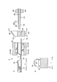
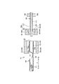
- the female crimp terminal 100 can constitute the electric wire 1 with the crimp terminal by being crimped to the covered electric wire 200.
- 1A shows a perspective view of the female crimp terminal 100 and the covered electric wire 200
- FIG. 1B shows a perspective view of the electric wire 1 with the crimp terminal after crimping.
- the terminal side of the crimped terminal-equipped electric wire 1 is defined as the distal end side Xa
- the opposite side, that is, the covered electric wire 200 side is defined as the proximal end side Xb.
- the covered electric wire 200 is formed by covering an aluminum conductive wire 220 in which a plurality of aluminum wires 221 formed of aluminum or an aluminum alloy are bundled with an insulating coating 210 made of an insulating resin. ing. Furthermore, the wire tip portion 200a on the tip end side Xa of the covered wire 200 is composed of a conductor exposed portion 222 in which the insulation coating 210 on the tip end side Xa of the covered wire 200 is stripped by a predetermined length, and the tip end side of the insulation sheath 210. It is comprised with the insulation coating front-end
- the electric wire 1 with the crimping terminal capable of conducting the female crimping terminal 100 and the covered electric wire 200 is configured. Yes.
- the female crimp terminal 100 has a box part 110 that allows insertion into the male terminal, and a crimp part 120 that is crimp-connected to the electric wire tip part 200a.
- the Xa box portion 110 and the proximal end side Xb crimping portion 120 are arranged via a transition portion 130 having a predetermined length.
- the box part 110 is an inverted hollow quadrangular columnar body that is formed in a substantially rectangular shape when viewed from the distal end side Xa in the longitudinal direction X
- the crimping part 120 is an inverted hollow cylindrical body that is in the longitudinal direction X. It is formed in a substantially circular shape when viewed from the base end side Xb.
- a direction perpendicular to the longitudinal direction X on the bottom surface of the box portion 110 in the plane is defined as a width direction Y.
- the crimping part 120 is disposed in the sealing part 121 and the crimping part main body 122 in this order from the distal end side Xa to the proximal end side Xb, and is integrated in a continuous shape continuous in the entire circumferential direction. Is formed.
- the sealing part 121 is deformed so that the front end side Xa is crushed in a substantially flat plate shape from the crimping part main body 122 in the crimping part 120, and the flat terminal base materials constituting the female crimp terminal 100 are superposed. It consists of shapes.
- the crimp portion main body 122 When the female crimp terminal 100 and the covered electric wire 200 are crimped and connected, the crimp portion main body 122 has a conductor crimp portion 122a corresponding to the conductor exposed portion 220 of the inserted covered electric wire 200 and an insulation coating of the inserted covered electric wire 200. It is comprised by the front-end
- the crimping portion main body 122 is formed with an inner diameter that is substantially the same as or slightly larger than the outer diameter of the insulating coating tip end portion 211 of the coated electric wire 200, and the conductor crimping portion 122a. It forms so that the internal diameter with the coating
- the crimping part 120 configured in this way allows the insertion of the electric wire distal end part 200a from the crimping part main body 122 to the sealing part 121, so that only the proximal end side Xb is opened, the distal end side Xa, and the entire peripheral surface part.
- the female crimp terminal 100 having the box part 110 and the crimp part 120 is formed from a single plate material as will be described later, the box part 110, the crimp part 120, and the transition part 130, more specifically, The sealing part 121 which comprises the crimping
- the covered electric wire 200 is configured by covering an aluminum conductive wire 220 in which a plurality of aluminum strands 221 are bundled with an insulating coating 210 made of an insulating resin, but the aluminum strand 221 is a single wire.
- the covered electric wire 200 may be configured by covering the aluminum conducting wire 220 configured by the above with an insulating coating 210.
- the covered electric wire 200 is not limited to covering the aluminum conductive wire 220 composed of the aluminum wire 221 with the insulating coating 210, but, for example, a copper-based wire bundled with copper-based wires formed of copper, copper alloy, or the like. It may be covered with an insulating coating 210, or a heterogeneous mixed conductor in which aluminum strands 221 are arranged and bundled around a copper strand, or conversely, a copper strand is arranged around an aluminum strand 221. Alternatively, the different types of mixed conductive wires bundled together may be covered with the insulating coating 210.
- FIG. 2 is a longitudinal sectional view of the wire crimping device 10 for explaining the female crimp terminal 100, the covered wire 200, and the wire crimping device 10.
- the wire crimping apparatus 10 includes a wire crimping unit 300 that crimps and connects the crimping portion 120 and the covered wire 200, a guide unit 410 that guides insertion of the covered wire 200 into the insertion space 120a, The electric wire 200 is held, and the electric wire holding unit 500 that inserts the covered electric wire 200 into the crimping portion main body 122 is configured.
- the electric wire crimping unit 300 is constituted by a pressing upper blade (crimper) 310 and a pressing lower blade (anvil) 320 that are divided into upper and lower parts and moves in the vertical direction (opposite direction of the pressing upper blade 310 and the pressing lower blade 320). It has a function of pressing the pressure-bonding portion main body 122 in the vertical direction with the pressing upper blade 310 and the pressing lower blade 320.
- the pressing upper blade 310 and the pressing lower blade 320 are arranged so as to face each other in the vertical direction with a predetermined interval therebetween, and when they are combined in the vertical direction, the female crimp terminal 100 and the covered electric wire 200 are crimped. Is formed into an inner surface shape corresponding to the outer shape of the crimping portion 120.
- the guide unit 410 is configured to be divided into upper and lower parts, and is arranged in a state of being separated so as to be opposed in the vertical direction, and is predetermined on the base end side Xb in the longitudinal direction X with respect to the wire crimping unit 300. They are arranged at intervals.
- the guide unit 410 is composed of an upper guide part 411 and a lower guide part 412 that are divided into two parts in the upper and lower directions.
- An internal hollow shape having an inner surface arranged in this order from the side Xa is formed.
- the guide tip portion 413 can be mounted on the outer surface of the crimping portion main body 122, and the tip portion Xa of the guide taper portion 414 has a portion a in FIG.
- the diameter of the crimping portion main body 122 is reduced by the thickness of the guide tip portion 413, and the inner diameter is approximately the same as the inner diameter of the crimping portion 120.
- a tapered tip 414a may be formed to have a diameter smaller than the inner diameter of the crimping portion 120 as long as the wire tip end portion 200a can be inserted.
- compression-bonding part 120 contacts is comprised in the front end side Xa of the taper front-end
- the guide unit 410 is configured to move and combine in the longitudinal direction X and the vertical direction from the vertically divided state.
- the guide unit 410 has an inner surface that forms the guide taper portion 414 so that the covered wire 200 is smoothly inserted without being caught by the guide taper portion 414 when the covered wire 200 is guided to the insertion space 120a. Is formed of a smooth tapered curved surface.
- the electric wire gripping unit 500 is arranged on the base end side Xb in the longitudinal direction X with respect to the guide unit 410 and is configured to be movable in the longitudinal direction X.
- the electric wire gripping unit 500 is formed to have a diameter that prevents the covered electric wire 200 from moving relative to the electric wire holding unit 500 in a state where a predetermined position of the covered electric wire 200 is held.
- the electric wire crimping unit 300, the guide unit 410, and the electric wire gripping unit 500 are independent mechanisms without being interlocked with each other.
- FIGS. 3 and 4 are longitudinal sectional views of the wire crimping apparatus 10 for explaining a guide mounting process in which the guide unit 410 is mounted on the crimping portion 120
- FIG. 3B is a diagram showing a wire in the insertion space 120a.
- Fig.4 (a) is a state before the crimping connection process which crimp-connects the crimping
- Fig. 4 (b) is a longitudinal sectional view of the wire crimping device 10 for explaining the state after the crimping connection step for crimping the crimping portion 120 and the wire tip portion 200a. Is shown.
- the wire crimping method includes a guide mounting step of mounting the guide unit 410 on the female crimp terminal 100, a wire insertion step of inserting the wire tip portion 200a into the insertion space 120a, and crimping the female crimp terminal 100 and the covered wire 200.
- the crimping connection process to connect is performed in this order.
- the wire crimping device 10 starts the guide mounting process when the female crimp terminal 100 is disposed at a predetermined position.
- the wire crimping device 10 is configured such that the guide tip portion 413 of the guide unit 410 is connected to the base of the crimping portion main body 122 in a state where the upper guide portion 411 and the lower guide portion 412 are moved in the longitudinal direction X and the vertical direction. It is mounted so as to be inserted into the end side Xb.
- the wire crimping apparatus 10 starts the wire insertion process as shown in FIG. Specifically, the wire crimping device 10 moves the wire gripping unit 500 that grips a predetermined position of the covered wire 200 to the distal end side Xa in the longitudinal direction X by a predetermined distance. At this time, the wire crimping device 10 passes the wire tip portion 200 a of the covered wire 200 in the order of the guide unit 410 and the wire insertion port 123 and inserts the wire tip portion 200 a into the insertion space 120 a of the crimp portion 120 in the female crimp terminal 100.
- the electric wire tip 120a is guided along the inner surface of the guide unit 410, that is, the guide taper portion 414. Then, it is inserted into the insertion space 120 a of the crimping part 120. Thereafter, the electric wire crimping apparatus 10 moves the guide unit 410 in the longitudinal direction X and the vertical direction to separate the guide unit 410 from the female crimp terminal 100 and return it to the initial position.
- the wire crimping apparatus 10 starts a crimp connection process as shown in FIG.
- the wire crimping device 10 includes a pressing upper blade 310 of the wire crimping unit 300 and a pressing force so as to sandwich the crimping portion 120 of the female crimping terminal 100 into which the wire tip 200a of the covered wire 200 is inserted.
- the lower blade 320 is moved toward the crimping portion 120, and the crimping portion 120 is pressed by the pressing upper blade 310 and the pressing lower blade 320, so that the crimping portion 120 is plastically deformed and the wire tip portion 200a is crimped and connected. .
- the wire crimping apparatus 10 moves the wire crimping unit 300 and the wire gripping unit 500 in the longitudinal direction X and the vertical direction, and is separated from the female crimp terminal 100. To return to the initial position.
- the electric wire crimping apparatus 10 can easily insert the electric wire distal end portion 200a into the insertion space 120a by making the guide unit 410 into a divided structure and attaching the guide unit 410 to the proximal end Xb of the crimping portion 120.
- the guide unit 410 includes a guide distal end portion 413 that can be mounted on the proximal end side Xb of the crimping portion 120, a guide taper portion 414 that is configured by a tapered smooth curved surface, and the guide taper. It is comprised with the taper front-end
- the guide unit 410 is configured such that the guide tip portion 413 is joined to the crimp portion in a state where the upper guide portion 411 and the lower guide portion 412 are combined so that the taper tip portion 414a abuts on the edge portion of the wire insertion port 123 in the crimp portion 120. 120 can be attached to the base end side Xb. Thereby, the guide unit 410 can position correctly with respect to the female crimp terminal 100, and can insert the electric wire front-end
- the guide unit 410 can cover the edge of the electric wire insertion port 123 by a taper tip portion 414 a formed to have an inner diameter substantially the same as the inner diameter of the crimping portion 120 abutting against the edge of the electric wire insertion port 123.
- the wire crimping device 10 accurately fixes the position of the guide unit 410 with respect to the female crimp terminal 100 by the guide tip 413, and the wire tip 200a is fixed by the guide taper 414 and the taper tip 414a.
- the wire tip portion 200a can be smoothly and reliably inserted into the insertion space 120a without being caught by the inner surface of the guide taper portion 414 or the edge portion of the wire insertion port 123.
- the wire crimping apparatus 10 can separate the guide unit 410 by making the guide unit 410 into a divided structure. For this reason, the wire crimping device 10 can easily return the guide unit 410 from the covered wire 200 inserted into the female crimp terminal 100 to the initial position after the wire insertion step.
- the guide unit 410 may be configured as a part of the mechanism of the wire crimping device 10 or may be configured as a separate part independent of the wire crimping device 10.
- the wire crimping unit 300, the guide unit 410, and the wire gripping unit 500 are not limited to independent mechanisms without being linked to each other.
- FIG.17 (a) shows the longitudinal cross-sectional view of the electric wire crimping apparatus 10 explaining the mode before a guide mounting process
- FIG.17 (b) shows the electric wire crimping apparatus 10 explaining the mode after a guide mounting process
- FIG. FIG. 18A shows a longitudinal cross-sectional view of the wire crimping apparatus 10 for explaining the state during the wire insertion process
- FIG. 18B shows a longitudinal cross-section of the wire crimping apparatus 10 for explaining the state after the wire insertion process
- FIG. 18A is a longitudinal sectional view of the wire crimping apparatus 10 for explaining the state after the crimping connection step.
- the wire crimping apparatus 10 has the wire crimping unit 300, the guide unit 410, and the wire gripping unit 500 arranged at the initial position.
- the wire crimping device 10 moves the pressing upper blade 310 from the crimping unit initial position P0 to the first intermediate position P1, as described above.
- the guide unit 410 is moved to a position where the guide front end portion 413 is attached to the base end side Xb of 122.
- the wire crimping apparatus 10 moves the wire tip 200a of the covered wire 200 while moving the pressing upper blade 310 from the first intermediate position P1 to the second intermediate position P2. As described above, it is inserted into the insertion space 120a of the crimping part 120.
- the wire crimping apparatus 10 moves the guide unit 410 as described above while moving the pressing upper blade 310 from the second intermediate position P2 to the third intermediate position P3. Return to the initial position.
- the wire crimping apparatus 10 moves the pressing upper blade 310 to the crimping position PP for crimping the crimping portion main body 122 and the covered electric wire 200 and moves the pressing lower blade 320. Move to the crimping position PP. Finally, the wire crimping apparatus 10 returns the wire crimping unit 300 and the wire gripping unit 500 to the initial positions as shown in FIG.
- the guide mounting step, the wire inserting step, and the crimping connection step can be smoothly performed by the guide unit 410 and the wire gripping unit 500 being interlocked with the vertical movement of the wire crimping unit 300.
- the female crimp terminal 100, the wire crimping device 10, and the wire crimping method in other embodiments will be described.
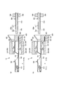
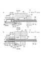
- the structure of the wire crimping device 10 and the female crimp terminal 100 when crimping and connecting the female crimp terminal 100 and the covered wire 200 will be described with reference to FIGS. 5 and 6.
- FIG. 5 shows a plan view of the terminal coupling band 100a and the covered electric wire 200
- FIG. 6A shows the female crimp terminal 100, the covered electric wire 200, and the electric wire crimping apparatus 10 for explaining the electric wire crimping apparatus 10.
- a longitudinal sectional view is shown
- FIG. 6B is a sectional view taken along the line AA in FIG.
- the end surface on the base end side Xb of the wire crimping unit 300 and the end surface on the distal end side Xa of the guide cutting unit 420 are illustrated separately.
- the end face on the base end side Xb and the end face on the front end side Xa of the guide cutting unit 420 are slidably in contact with each other.
- the same components as those in the first embodiment described above are denoted by the same reference numerals, and detailed description thereof is omitted.
- a plurality of female crimp terminals 100 are connected to a substantially band-shaped carrier 124 whose longitudinal direction is the width direction Y of the female crimp terminal 100 to form a terminal coupling band 100a.
- the terminal connecting band 100 a is arranged so that the longitudinal direction X of the female crimp terminal 100 substantially coincides with the carrier short direction perpendicular to the carrier longitudinal direction of the carrier 124 in plan view.
- the rear side of the crimping part 120 in the female crimp terminal 100 is connected to the carrier 124 via the connecting part 124a, and a plurality of female crimps are provided at predetermined intervals in the carrier longitudinal direction of the carrier 124, that is, in the width direction Y.
- the terminal 100 is connected.
- the terminal connection band 100a is a three-dimensional terminal formed on a base material formed in a shape in which a substantially flat base material is punched and a substantially belt-like carrier 124 is connected to a terminal shape portion developed in a plane. By bending into a shape, a plurality of female crimp terminals 100 are connected.
- the electric wire crimping device 10 guides the insertion of the covered electric wire 200 into the electric wire crimping unit 300 and the crimping portion 120, and separates the female crimping terminal 100 and the carrier 124. And the electric wire gripping unit 500.
- the guide cutting unit 420 is arranged on the base end side Xb in the longitudinal direction X with respect to the electric wire crimping unit 300 and is configured to be movable in the vertical direction. Specifically, the guide cutting unit 420 is integrally formed with a carrier cut portion 421 that separates the female crimp terminal 100 and the carrier 124 and a guide portion 422 that guides insertion of the covered electric wire 200 into the crimp portion main body 122. is doing.
- the carrier cut part 421 has a substantially rectangular cross section and is formed in a shape having a sandwiching part 423 through which the carrier 124 is inserted.
- the guide portion 422 is integrally formed so as to be placed above the carrier cut portion 421 and has a substantially C-shaped cross section when viewed from the longitudinal direction X.
- the guide portion 422 is formed in an internal hollow having a tapered inner surface shape similar to the guide tapered portion 414 in the guide unit 410 in the first embodiment described above, and one side surface in the width direction Y is elongated. It is formed in a shape having an opening 424 that opens along the direction X and allows insertion of the covered electric wire 200.
- the guide opening 422a that opens on the distal end side Xa of the guide part 422 is formed with an opening diameter that is substantially the same as the inner diameter of the crimping part 120.
- the guide part 422 is integrally formed so that the lower part may be arrange
- the guide cutting unit 420 starts from the initial position where the sandwiching part 423 of the carrier cut part 421 waits on the carrier longitudinal direction of the terminal connection band 100a, that is, the flow line of the carrier 124 in the width direction Y.
- the side Xa is configured to be movable in the vertical direction to a position facing the wire insertion port 123 of the crimping portion 120 in the longitudinal direction X.
- 7A is a longitudinal sectional view of the wire crimping device 10 for explaining a state in the middle of the carrier cutting process in which the female crimp terminal 100 and the carrier 124 are separated by the guide cutting unit 420
- FIG. 8 is a longitudinal sectional view of the electric wire crimping apparatus 10 for explaining a state at the completion of the carrier cutting process in which the female crimp terminal 100 and the carrier 124 are separated by the guide cutting unit 420
- FIG. The longitudinal cross-sectional view of the electric wire crimping apparatus 10 explaining the mode of the electric wire insertion process which inserts 200a is shown.
- the end surface on the base end side Xb of the wire crimping unit 300 and the end surface on the front end side Xa of the guide cutting unit 420 are illustrated slightly apart so that each component can be easily understood. However, the end face on the base end side Xb of the electric wire crimping unit 300 and the end face on the front end side Xa of the guide cutting unit 420 are slidably in contact with each other.
- the carrier cutting step for separating the female crimp terminal 100 and the carrier 124, the wire insertion step, and the crimp connection step are performed in this order.
- the wire crimping device 10 starts the carrier cutting process when the female crimp terminal 100 is disposed at a predetermined position.
- the wire crimping device 10 inserts the carrier 124 of the terminal coupling band 100a through the sandwiching portion 423 of the guide cutting unit 420 disposed at the initial position. Thereafter, as illustrated in FIG. 7B, the wire crimping device 10 is configured to reach a position where the distal end side Xa of the guide portion 422 of the guide cutting unit 420 faces the wire insertion port 123 of the crimp portion 120 in the longitudinal direction X. The guide cutting unit 420 is moved downward. At this time, the carrier cut part 421 cuts the carrier 124 so as to be sheared by the sandwiching part 423 to separate the female crimp terminal 100 from the terminal connection band 100a.
- the wire crimping device 10 starts the wire insertion step as shown in FIG. Specifically, the wire crimping device 10 moves the wire gripping unit 500 that grips a predetermined position of the covered wire 200 to the distal end side Xa in the longitudinal direction X by a predetermined distance. At this time, the wire crimping device 10 allows the wire tip portion 200a of the covered wire 200 to pass through the guide opening portion 422a of the guide portion 422 and the wire insertion port 123 in this order, and the insertion space of the crimp portion 120 in the female crimp terminal 100. Insert into 120a.
- the wire tip portion 120 a is guided along the inner surface of the guide cutting knit 420 and the crimping portion 120. Is inserted into the insertion space 120a.
- the electric wire crimping apparatus 10 starts a crimp connection process as shown in FIG.
- the wire crimping device 10 includes a pressing upper blade 310 of the wire crimping unit 300 and a pressing force so as to sandwich the crimping portion 120 of the female crimping terminal 100 into which the wire tip 200a of the covered wire 200 is inserted.
- the lower blade 320 is moved toward the crimping portion 120, and the crimping portion 120 is pressed by the pressing upper blade 310 and the pressing lower blade 320, so that the crimping portion 120 is plastically deformed and the wire tip portion 200a is crimped and connected.
- the wire crimping device 10 moves the wire 1 with crimp terminal in the width direction Y, and causes the covered wire 200 to escape from the wire crimping device 10 through the opening 424 of the guide portion 422.
- the wire crimping apparatus 10 moves the wire crimping unit 300, the guide cutting unit 420, and the wire gripping unit 500 in the longitudinal direction X and the vertical direction to the initial position. return.
- the wire crimping device 10 can smoothly perform the carrier cutting step and the wire inserting step by integrally forming the guide cutting unit 420 so that the guide portion 422 is placed on the upper plane of the carrier cutting portion 421. it can.
- the wire crimping device 10 lowers the guide cutting unit 420 from the initial position to a position where the wire insertion port 123 on the proximal end side Xb of the crimping portion 120 and the distal end side Xa of the guide portion 422 face each other in the carrier cutting process.
- the guide part 422 is made to stand by by moving in the direction.
- the electric wire crimping device 10 can immediately insert the electric wire tip portion 200a into the insertion space 120a with respect to the guide portion 422 of the guide cutting unit 420 that has completed the carrier cutting step, so that the electric wire insertion step can be smoothly performed. Can be migrated.
- the wire crimping device 10 has the guide portion 422 formed with an opening 424 that allows the covered wire 200 to escape along the longitudinal direction X, that is, in a substantially C-shaped cross section when viewed from the longitudinal direction X. After the crimping step, the covered electric wire 200 crimped and connected to the female crimp terminal 100 can be easily escaped through the opening 424 of the guide portion 422.
- the wire crimping device 10 includes a guide cutting unit 420 that is integrally formed so as to be disposed below the guide portion 422 on the upper surface of the carrier cut portion 421 (see FIG. 6), whereby the guide portion and the carrier cut portion are provided. And a wire crimping device configured separately from each other, the number of parts can be reduced, and the mechanism of the device can be simplified.
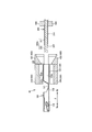
- FIG. 9 shows a longitudinal sectional view of the wire crimping device 10 for explaining the female crimp terminal 100, the covered wire 200, and the wire crimping device 10.
- the same components as those in the first embodiment described above are denoted by the same reference numerals, and detailed description thereof is omitted.
- the electric wire crimping apparatus 10 includes an electric wire crimping unit 300, a guide unit 430, and an electric wire gripping unit 500.
- the guide unit 430 is configured to be divided into upper and lower parts, arranged in a state of being separated so as to face each other in the vertical direction, and the end surface of the distal end side Xa is aligned with the end surface of the proximal end side Xb of the wire crimping unit 300. It is arranged to touch.
- the guide unit 430 includes an upper guide part 431 and a lower guide part 432 that are divided into two parts in the vertical direction, and in the state where the upper guide part 431 and the lower guide part 432 are combined in the vertical direction, A diameter approximately the same as the inner diameter of 122 is formed into an internal hollow shape having a tapered inner surface whose diameter is expanded from the distal end side Xa toward the proximal end side Xb.
- the guide unit 430 is configured to move in the up and down direction from the vertically divided state and combine. In addition, you may comprise so that the electric wire crimping unit 300 may interlock
- FIG. 10A shows a longitudinal sectional view of the wire crimping apparatus 10 for explaining a guide moving step of moving the inner diameter of the guide unit 430 to a position opposite to the inner diameter of the crimping portion 120.
- FIG. ) Shows a longitudinal sectional view of the wire crimping apparatus 10 for explaining the state of the wire insertion step of inserting the wire tip portion 200a into the insertion space 120a.
- FIG. 11A shows the crimp portion 120 and the wire tip portion 200a.
- FIG. 11B is a longitudinal sectional view for explaining the state before the crimping connection process for crimping connection
- FIG. 11B is a wire crimping apparatus for explaining the state after the crimping connection process for crimping and connecting the crimping part 120 and the wire tip part 200a.
- 10 shows a longitudinal sectional view.
- the wire crimping device 10 starts the guide moving process when the female crimp terminal 100 is disposed at a predetermined position.
- the electric wire crimping device 10 inserts the inner diameter of the distal end side Xa of the guide unit 430 in which the upper guide portion 431 and the lower guide portion 432 separated in the vertical direction are combined in the vertical direction into the electric wire insertion of the crimp portion 120. It arrange
- the wire crimping apparatus 10 starts the wire insertion process as shown in FIG. Specifically, the wire crimping device 10 moves the wire gripping unit 500 that grips a predetermined position of the covered wire 200 to the distal end side Xa in the longitudinal direction X by a predetermined distance. At this time, the wire crimping device 10 passes the wire tip portion 200 a of the covered wire 200 in the order of the guide unit 410 and the wire insertion port 123 and inserts the wire tip portion 200 a into the insertion space 120 a of the crimp portion 120 in the female crimp terminal 100.
- the wire tip portion 120 a is guided along the inner surface of the guide unit 430, and It is inserted into the insertion space 120a.
- the electric wire crimping apparatus 10 starts a crimp connection process as shown in FIG. Specifically, the wire crimping device 10 further moves and presses the pressing upper blade 310 and the pressing lower blade 320 against the crimping portion 120 of the female crimp terminal 100 into which the wire tip portion 200a of the covered wire 200 is inserted. As a result, the crimping portion 120 is plastically deformed and the wire tip portion 200a is crimped and connected.
- the wire crimping device 10 moves the guide unit 430 in the vertical direction, separates the guide unit 430 from the female crimp terminal 100, and returns to the initial position.
- the wire crimping device 10 can smoothly perform the guide moving step, the wire inserting step, and the crimping connection step by adopting a configuration in which the guide unit 430 is not attached to the proximal end side Xb of the crimping portion main body 122.
- the wire crimping device 10 is configured so that the guide unit 430 is not attached to the crimping portion 120, so that the guide unit 430 moves to the crimping connection step without returning the guide unit 430 to the initial position between the guide moving step and the wire insertion step. can do.
- the electric wire crimping device 10 can smoothly move through the guide moving step, the electric wire insertion step, and the crimping connection step in this order without the need to remove the guide unit 430 before and after the electric wire insertion step.
- the guide unit of the present embodiment includes a carrier cut part 421z of the guide cutting unit of the second embodiment below the lower guide part 432z.
- the guide unit 430z in which the lower guide portion 432z and the carrier cut portion 421z are integrally formed may be used.
- FIG. 19A to FIG. 19C show how the guide unit 430z moves step by step.
- the guide unit 430z turns the guide unit 430z downward from the state in which the carrier 124 in the terminal connection band 100a is inserted into the sandwiching part 423z of the carrier cut part 421z, similarly to the guide cutting unit 420 in the second embodiment. To move and cut.
- the upper guide portion 431 starts to move downward as shown in FIG.
- the upper guide portion 431 that moves downward contacts the lower guide portion 432z in a state where the carrier 124 is inserted into the sandwiching portion 423z.
- the lower guide portion 432 is pushed by the upper guide portion 431 moving downward, moves downward integrally with the upper guide portion 431, and the carrier 124 inserted through the sandwiching portion 423z is inserted into the sandwiching portion 423z.
- the pressing lower blade 320 is pushed by the upper guide portion 431 moving downward, moves downward integrally with the upper guide portion 431, and the carrier 124 inserted through the sandwiching portion 423z is inserted into the sandwiching portion 423z.
- the guide unit 430z moves the upper guide portion 431 and the lower guide portion 432 together to a predetermined position.
- the opening portion on the distal end side Xa of the tapered inner surface of the guide unit 430z is the wire insertion port 123 of the female crimp terminal 100.
- the guide unit 430z may integrally form the upper guide portion 431 and the lower guide portion 432z.
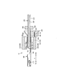
- FIG. 12 is a longitudinal sectional view of the wire crimping device 10 for explaining the female crimp terminal 100, the covered wire 200, and the wire crimping device 10.
- the same components as those in the first embodiment described above are denoted by the same reference numerals, and detailed description thereof is omitted.
- the electric wire crimping apparatus 10 includes an electric wire crimping unit 300, a guide gripping unit 440, and an electric wire gripping unit 500.
- the guide gripping unit 440 has a configuration that is divided into two parts in the upper and lower directions, and is arranged in a state of being separated so as to face the upper direction, and at the proximal end side Xb in the longitudinal direction X with respect to the wire crimping unit 300. They are arranged at a predetermined interval.
- the guide gripping unit 440 includes an upper guide portion 441 and a lower guide portion 442 that are divided into two parts in the vertical direction, and the covered electric wire 200 is relative to the guide gripping unit 440 when combined in the vertical direction.
- the distal end Xa is a conductor gripping portion 443, and the proximal end Xb is a covering gripping portion 444.
- the guide gripping unit 440 is configured to move and combine in the longitudinal direction X and the vertical direction from the vertically divided state.
- the guide gripping unit 440 is not limited to be formed with an inner diameter that is large enough to prevent the covered electric wire 200 from moving relative to the guide gripping unit 440, but may be formed with an inner diameter that allows relative movement.
- FIG. 13A shows a longitudinal sectional view of the wire crimping device 10 for explaining a state in the middle of the wire guiding process for guiding the distal end side Xa of the wire distal end portion 200a to the wire insertion port 123, and FIG.
- FIG.14 (a) shows electric wire in the insertion space 120a.
- FIG.14 (b) is the time of completion of the electric-wire insertion process which inserts the electric wire front-end
- the longitudinal cross-sectional view of the electric wire crimping apparatus 10 explaining a mode is shown.
- the electric wire crimping method includes an electric wire guiding process for guiding the distal end side Xa of the electric wire distal end portion 200a to the electric wire insertion port 123 while grasping the electric wire distal end portion 200a by the guide grasping unit 440, an electric wire inserting step, and a crimping connecting step. Do in order.
- the wire crimping device 10 starts the wire guiding process when the female crimp terminal 100 is disposed at a predetermined position. Specifically, as shown in FIG. 13A, the electric wire crimping apparatus 10 moves the upper guide portion 441 and the lower guide portion 442 that are separated in the vertical direction in the vertical direction, thereby moving the electric wire tip portion 200a to the guide gripping unit. Grip at 440. At this time, the guide gripping unit 440 grips the wire tip end 200a so that the tip end side Xa of the conductor exposed portion 222 of the wire tip end portion 200a is slightly exposed from the tip end side Xa of the guide gripping unit 440.
- the guide grip unit 440 moves in the longitudinal direction X to the base end side Xb of the crimping section main body 122 together with the covered wire 200, and is exposed from the guide grip unit 440.
- the leading end side Xa of 200a is guided to the wire insertion port 123 of the crimping part 120.
- the electric wire crimping apparatus 10 will start an electric wire insertion process, as shown in FIG. Specifically, when the wire crimping device 10 guides the distal end side Xa of the wire distal end portion 200a to the wire insertion port 123, the guide gripping unit 440 is separated vertically and the gripping of the covered wire 200 by the guide gripping unit 440 is released. Then, the electric wire holding unit 500 holding the predetermined position of the covered electric wire 200 is moved by a predetermined distance toward the distal end side Xa in the longitudinal direction X.
- the wire crimping device 10 passes the wire tip portion 200a of the covered wire 200 through the guide gripping unit 440 and the wire insertion port 123 in this order, and inserts into the insertion space 120a of the crimping portion 120 of the female crimp terminal 100. .
- the electric wire crimping apparatus 10 starts a crimp connection process as shown in FIG.
- the wire crimping device 10 includes a pressing upper blade 310 of the wire crimping unit 300 and a pressing force so as to sandwich the crimping portion 120 of the female crimping terminal 100 into which the wire tip 200a of the covered wire 200 is inserted.
- the lower blade 320 is moved toward the crimping portion 120, and the crimping portion 120 is pressed by the pressing upper blade 310 and the pressing lower blade 320, so that the crimping portion 120 is plastically deformed and the wire tip portion 200a is crimped and connected. .
- the wire crimping apparatus 10 moves the wire crimping unit 300, the guide gripping unit 440, and the wire gripping unit 500 in the longitudinal direction X and the vertical direction, thereby crimping the female die. It is separated from the terminal 100 and returned to the initial position.
- the electric wire front end portion 200a is gripped so that the front end side Xa of the conductor exposed portion 222 of the electric wire front end portion 200a is slightly exposed from the front end side Xa of the guide holding unit 440.
- the wire tip 200a may be gripped so that the tip Xa of the conductor exposed portion 222 is not exposed from the tip Xa of the guide gripping unit 440.
- the wire crimping device 10 smoothly performs the wire guiding step and the wire inserting step by guiding the distal end side Xa of the wire distal end portion 200a to the wire insertion port 123 while the guide gripping unit 440 grips the wire distal end portion 200a. It can be carried out.
- the wire crimping device 10 slightly exposes the distal end side Xa of the wire distal end portion 200a from the distal end portion Xa of the guide gripping unit 440 when the guide gripping unit 440 grips the distal end side Xa of the electrical wire distal end portion 200a.
- the exposed portion of the distal end side Xa of the electric wire distal end portion 200a can be directly guided to the electric wire insertion port 123, and the transition to the electric wire insertion process can be smoothly performed by releasing the grip of the covered electric wire 200.
- the guide gripping unit 440 is moved in a state where the end surface on the distal end side Xa of the conductor exposed portion 222 coincides with the end surface on the distal end side Xa of the guide gripping unit 440 or enters the base end side Xb. After the movement, the electric wire distal end portion 200a may be moved to the distal end side Xa and inserted into the insertion space.
- FIG. 15A is a longitudinal sectional view of the wire crimping device 10 for explaining the female crimp terminal 100, the covered wire 200, and the wire crimping device 10.
- the same configurations as those in the above-described embodiment are denoted by the same reference numerals, and detailed description thereof is omitted.
- the electric wire crimping apparatus 10 includes an electric wire crimping unit 300, a guide cutting unit 450, and an electric wire gripping unit 510.
- the guide cutting unit 450 has an upper guide part 451 and a lower cutting part 452 that are divided into two parts in the vertical direction so that the end face of the distal end side Xa is in contact with the end face of the proximal end side Xb of the wire crimping unit 300. It is configured to be arranged and movable in the vertical direction.
- This guide cutting unit 450 is formed in an internal hollow shape in a state where the upper guide portion 451 and the lower cut portion 452 are combined in the vertical direction.
- the guide cutting unit 450 includes a conductor insertion portion 450a having a diameter substantially the same as the outer diameter of the conductor exposed portion 222 and slightly extending along the longitudinal direction X, and a proximal end side of the conductor insertion portion 450a.
- a tapered guide surface 453 in which the diameter of Xb is expanded from the distal end side Xa toward the proximal end side Xb is formed in an internal hollow shape having this order.
- the upper guide portion 451 is provided with a slide portion 454 that protrudes from the upper end toward the base end side Xb in the longitudinal direction X.
- the slide portion 454 is provided with a slide surface 455 formed by chamfering the lower end of the base end side Xb by 45 °.
- the lower cut portion 452 is formed with an opening along the width direction Y and a pinching portion 423 that allows the carrier 124 to be inserted into the terminal connection band 100a. Further, the lower cutting portion 452 is configured to be movable downward or upward in conjunction with the upward or downward movement of the upper guide portion 451.
- the sandwiching portion 423 of the lower cutting portion 452 is positioned on the flow line of the carrier 124 in the carrier longitudinal direction of the connecting terminal band 100a, that is, in the width direction Y.
- the standby position is an initial state, and the conductor insertion portion 450a of the guide cutting unit 450 is configured to be movable from the standby position to a position facing the wire insertion port 123 of the crimping portion 120.
- the wire gripping unit 510 has a slide surface 511 formed by chamfering the upper end of the tip side Xa facing the slide surface 455 in the longitudinal direction X by 45 ° with respect to the wire gripping unit 500 in the first embodiment described above. The difference is that it is provided.
- the electric wire crimping device 10 will be described in detail later, but the electric wire gripping unit 510 and the upper guide portion 451 are combined in the vertical direction as the electric wire gripping unit 510 moves to the distal end side Xa in the longitudinal direction X.
- the upper guide part 451 and the lower cutting part 452 are configured to slide so as to be separated in the vertical direction.
- FIG. 15B is a longitudinal sectional view of the wire crimping device 10 for explaining the state at the completion of the carrier cutting process in which the female crimping terminal 100 and the carrier 124 are separated by the guide cutting unit 450.
- FIG. ) Shows a longitudinal cross-sectional view of the wire crimping device 10 for explaining a state in the middle of the wire insertion process for guiding the distal end side Xa of the wire distal end portion 200a to the wire insertion port 123
- FIG. The longitudinal cross-sectional view of the electric wire crimping apparatus 10 explaining the mode at the time of the electric wire insertion process completion which guides the front end side Xa to the electric wire insertion port 123 is shown.
- the carrier cutting step for separating the female crimp terminal 100 and the carrier 124, the wire insertion step, and the crimp connection step are performed in this order.
- the wire crimping device 10 starts the carrier cutting process when the female crimp terminal 100 is disposed at a predetermined position.
- the electric wire crimping device 10 is connected to the guide cutting unit 450 that has been moved downward from the standby position by the pinching portion 423, as in the carrier cutting step in the second embodiment.
- the female crimp terminal 100 is separated from the band 100a.
- the guide cutting unit 450 moves to a position where the conductor insertion portion 450 a faces the wire insertion port 123.
- the wire crimping apparatus 10 starts the wire insertion process as shown in FIG. Specifically, the wire crimping apparatus 10 moves the wire gripping unit 510 that grips a predetermined position of the covered wire 200 to the distal end side Xa in the longitudinal direction X as shown in FIG. The exposed portion 222 is inserted into the conductor insertion portion 450a of the guide cutting unit 450.
- the electric wire tip portion 200a is guided along the guide surface 453 of the guide cutting unit 450 to be a conductor. Inserted in the insertion portion 450a, the vicinity of the tip end side Xa of the conductor exposed portion 222 is positioned in the insertion space 120a.
- the wire crimping device 10 separates the upper guide portion 451 and the lower cutting portion 452 in the vertical direction by the slide mechanism, and inserts the insulating coating tip portion 211 of the wire tip portion 200a into the insertion space 120a.
- the slide surface 511 of the electric wire gripping unit 510 comes into contact with the slide surface 455 of the upper guide portion 451 in the guide cutting unit 450 as the movement in the longitudinal direction X occurs. Is further moved in the longitudinal direction X, the slide surface 511 moves the upper guide portion 451 upward. Further, when the upper guide portion 451 starts to move upward, the lower cutting portion 452 starts moving downward in conjunction with the movement of the upper guide portion 451.
- the wire crimping apparatus 10 moves the upper guide portion 451 and the lower cutting portion 452 combined in the vertical direction upward and downward, respectively, and moves the slide portion 454 of the upper guide portion 451 with the wire gripping unit 510.
- tip part 200a is comprised.
- the wire crimping device 10 When the upper guide portion 451 and the lower cutting portion 452 start separation in the vertical direction, the wire crimping device 10 further moves the wire gripping unit 510 to the distal end side Xa in the longitudinal direction X as shown in FIG. Then, the insulating coating tip portion 211 of the wire tip portion 200a is inserted into the insertion space 120a through the space formed by the separation of the upper guide portion 451 and the lower cutting portion 452.
- the wire crimping device 10 When the covered electric wire 200 is inserted into the female crimp terminal 100, the wire crimping device 10 starts a crimp connection step similar to the crimp connection step in the second embodiment, and crimps the crimp portion 120 and the wire tip portion 200a. It connects and comprises the electric wire 1 with a crimp terminal.
- the wire crimping apparatus 10 moves the wire crimping unit 300 in the vertical direction toward the standby position, and then directs the wire gripping unit 510 that grips the wire 1 with the crimp terminal toward the proximal end Xb in the longitudinal direction X.
- the electric wire 1 with a crimping terminal is discharged from the electric wire crimping device 10 by being moved.
- the guide cutting unit 450 separated in the vertical direction by the electric wire gripping unit 510 moves downward with the movement of the upper guide portion 451 as the upper guide portion 451 moves downward as the electric wire gripping unit 510 moves.
- the part 452 moves upward and combines in the vertical direction.
- the wire crimping device 10 moves the guide cutting unit 450 to the standby position.
- the effect of the electric wire crimping apparatus 10 comprised above and the electric wire crimping method is demonstrated.
- the carrier cutting step and the electric wire insertion step can be performed smoothly.
- the wire crimping apparatus 10 is in a state where the conductor insertion portion 450a of the upper guide portion 451 waits at a position facing the wire insertion port 123 of the crimping portion 120 in a state where the carrier cutting process is completed. Smooth transition to the process.
- the wire crimping apparatus 10 is provided with a slide mechanism, the upper guide portion 451 and the lower cutting portion 452 can be separated while guiding the covered wire 200, so that the covered wire 200 can be crimped more efficiently. It can be inserted into the terminal 100.
- the electric wire 1 with the crimp terminal can be easily discharged from the electric wire crimping apparatus 10 after the crimping connection process is completed.
- the crimp terminal of the present invention corresponds to the female crimp terminal 100 of the embodiment
- the conductor corresponds to the aluminum conductor 220
- the crimping means corresponds to the wire crimping unit 300
- the guide means corresponds to the guide units 410 and 430, the guide part 422, and the guide cutting unit 450
- the guide portions correspond to the upper guide portions 411, 431, 441, 451, the lower guide portions 412, 432, 442, and the lower cut portion 452
- the carrier cutting means corresponds to the carrier cutting part 421 and the lower cutting part 452
- the allowance for withdrawal corresponds to the opening 424.
- the guide gripping means corresponds to the guide gripping unit 440
- the moving means corresponds to the electric wire gripping units 500 and 510
- the terminal axis direction corresponds to the longitudinal direction X
- the carrier longitudinal direction corresponds to the width direction Y
- the present invention is not limited only to the configuration of the above-described embodiment, and many embodiments can be obtained.
- the present invention is not limited to the female crimp terminal 100 having the box portion 110 but may be a male crimp terminal having a connection tab or a crimp terminal constituted only by the crimp portion 120.
- the female crimp terminal of the present invention is not limited to the same inner diameter of the conductor crimping part 122a and the inner diameter of the coated crimping part 122b, but as shown in FIGS. 20 (a) to 20 (c).
- the female crimp terminal 1000 may be formed in a stepped shape such that the inner diameter of the coated crimp portion 1220b is larger than the inner diameter of the conductor crimp portion 1220a.
- FIG. 20A shows a perspective view of the female crimp terminal 1000
- FIG. 20B shows a longitudinal sectional view of the wire crimping apparatus 10 for explaining the state after the wire insertion step
- FIG. c) has shown the longitudinal cross-sectional view of the electric wire crimping apparatus 10 explaining the mode after a crimping connection process.
- FIG. 21A shows a plan view of a state where the core rod 600 is placed on the crimping portion equivalent portion 1201
- FIG. 21B shows a cross-sectional view taken along the line BB in FIG. 21A.
- FIG. 21 (c) is a longitudinal sectional view showing a state where the crimping part 1200 is formed in a hollow shape
- FIG. 21 (d) is a sectional view taken along the line CC in FIG. 21 (c). .
- the crimping portion main body 1220 is formed by forming the conductor crimping portion 1220a substantially equal to or slightly larger than the outer diameter of the conductor exposed portion 222.
- the portion 1220b is formed to be approximately equal to or slightly larger than the outer diameter of the insulating coating tip portion 211.
- the stepped portion 1220z in the crimping portion main body 1220 is not a stepped shape that is orthogonal to the longitudinal direction X, but is formed in a stepped shape that is smooth from the coated crimped portion 1220b to the conductor crimped portion 1220a.
- the terminal base material is punched into a shape in which a hollow crimp section 1200 formed in a step shape is developed in a plane.
- the step portion 620 of the core rod 600 is a step portion of the crimping portion 1200 as shown in FIG.
- the core rod 600 is placed on the terminal base material so as to be positioned at the stepped portion equivalent portion 1221z corresponding to 1220z.
- the crimping portion equivalent portion 1201 corresponding to the crimping portion 1200 is bent at both ends in the width direction Y around the core rod shaft 610 as shown in FIG. And as shown in FIG.21 (d), it forms in a hollow shape so that the core rod 600 may be surrounded with the press die which is not shown in figure.
- FIGS. 22 and 23 show a cross-sectional view of the conductor crimping portion 1220a after the crimping connection step when the crimping portion main body 1220 has a stepped shape
- FIG. 23 shows the case where the crimping portion main body 122 is not formed in a stepped shape. Sectional drawing of the conductor crimping
- the gap between the conductor crimping portion 1220a and the conductor exposed portion 222 in the crimp portion main body 1220 formed in the step shape is compared with the gap between the conductor crimping portion 122a and the conductor exposed portion 222 in the crimp portion main body 122 not formed in the step shape. Therefore, the conductor crimping portion 122a has a small amount of displacement inward in the radial direction in the crimping portion main body 1220 when crimped and connected to the conductor exposed portion 222, and can prevent the occurrence of surplus.
- the conventional crimped part main body 122 that is not formed in a stepped shape has a larger gap between the conductor crimped part 122a and the conductor exposed part 222 than the crimped part main body 1220 formed in a stepped shape.
- the conductor crimping part 122a has a large amount of displacement inward in the radial direction in the crimping part main body 122 when crimped and connected to the conductor exposed part 222.
- the conventional conductor crimping portion 122a has a large amount of displacement inward in the radial direction in the crimping portion main body 122, so that a surplus is generated when crimping the conductor exposed portion 222. As shown in FIG. An inwardly-turned portion 120z that protrudes so that the surplus thickness falls inward in the radial direction at 122 is generated.
- the inwardly tilted portion 120z becomes an obstacle, and the conductor exposed portion 222 does not reach the corner of the conductor crimping portion 122a. As shown in the enlarged view of FIG. 23, there is a possibility that a gap is generated between the conductor crimping portion 122a and the conductor exposed portion 222.
- the electrical connectivity deteriorates or the capillary phenomenon occurs. As a result, moisture penetrates and the electrical characteristics deteriorate.
- the crimp part main body 1220 formed in the step shape has a smaller gap between the conductor crimp part 1220a and the conductor exposed part 222 than the crimp part main body 122 not formed in the step shape. Even if the tip end portion 200a is crimped and connected, the conductor crimping portion 1220a and the conductor exposed portion 222 are crimped without causing the inwardly-turned portion 120z in the conductor crimping portion 1220a, thereby deteriorating the electrical characteristics. Can be prevented.
- the stepped portion 1220z in the crimped portion main body 1220 is formed in a stepped shape that becomes smooth from the coated crimped portion 1220b to the conductor crimped portion 1220a, the wire tip portion 200a can be easily inserted into the insertion space 1200a. Can do.
- the female crimp terminal 1000 as described above is manufactured by using the core rod 600, the position of the stepped portion 1220z in the crimp portion main body 1220 can be adjusted even if the female crimp terminal 1000 is mass-produced.
- the crimp terminals 1000 can be formed at desired positions without variations.
- the crimping portion main body As described above, the gap between the conductor crimping portion and the conductor exposed portion 222, and the covering Since the gap between the crimping portion and the insulating coating tip portion 211 is formed in a step shape so as to be small, when the electric wire tip portion 200a is inserted into the insertion space, the insulating coating tip portion 211 is formed on the step portion of the crimping portion main body. May be caught and the wire tip 200a may not be securely inserted into the insertion space.
- the coated crimping part is formed longer than the desired length in the longitudinal direction X, even if the tip of the conductor exposed part 222 hits the tip of the crimped part body, the stepped portion of the crimped part body is insulated. By continuing to insert the wire tip portion 200a until the tip portion 211 hits, the tip of the conductor exposed portion 222 may be bent.
- the covering crimping portion is formed longer than the desired length in the longitudinal direction X, even if the insertion of the wire tip portion 200a is stopped immediately before the tip of the conductor exposed portion 222 hits the tip of the crimping portion main body 1220.
- the covering crimping portion is located around the portion on the base end side Xb of the conductor exposed portion 222.
- the gap between the conductor exposed portion 222 and the crimped portion main body on the base end side Xb is larger than the gap between the conductor exposed portion 222 and the crimped portion main body on the distal end side Xa. That is, the conductor crimping portion in this case may form the inwardly-turned portion 120z when being crimped and connected to the conductor exposed portion 222.
- the insertion of the wire tip portion 200a into the insertion space 1200a is insufficient, the tip of the conductor exposed portion 222 is bent, Can insert the wire tip portion 200a at a desired position with respect to the insertion space 1200a without increasing the gap between the conductor crimping portion 1220a and the conductor exposed portion 222.
- the desired position is a position in the longitudinal direction X where the boundary portion between the conductor exposed portion 222 and the coating tip portion 211 corresponds to the step portion 1220z of the crimping portion main body 1220.
- the crimping part main body 1220 and the wire tip part 200a are formed by accurately matching the stepped part equivalent part 1221z of the crimping part equivalent part 1201 and the stepped part 620 of the core rod 600 to form the crimping part 1200 in a hollow shape.
- the female crimp terminal 1000 formed in a stepped shape as described above is provided with a wire toward the center of the wire insertion port by the guide units 410 and 430, the guide cutting units 420 and 450, the guide gripping unit 440, and the like of the present invention.
- the insertion of the tip portion 200a is allowed. Thereby, it can prevent that the electric wire front-end
- the conductor crimping portion 1220a is formed to be approximately equal to or slightly larger than the outer diameter of the conductor exposed portion 222, and the coated crimping portion 1220b is approximately equal to or slightly smaller than the outer diameter of the insulating coating tip portion 211. Even if the wire tip 200a is formed in a large size, the wire tip 200a can be surely inserted into the insertion space 1200a without the aluminum wire 221 coming apart and the exposed conductor 222 being bent due to the contact of the stepped portion 1220z. Can be inserted into.
Landscapes
- Engineering & Computer Science (AREA)
- Manufacturing & Machinery (AREA)
- Manufacturing Of Electrical Connectors (AREA)
- Connections Effected By Soldering, Adhesion, Or Permanent Deformation (AREA)
Abstract
Le problème décrit par la présente invention est de pourvoir à un dispositif de sertissage de fil et à un procédé de sertissage de fil, une section d'extrémité de fil pouvant par là-même être insérée sans à-coups dans une section à sertir creuse, et être sertie à demeure et de manière efficace au moyen de celle-ci, d'une cosse à sertir cyldindrique fermée. La solution selon l'invention porte sur un dispositif (10) de sertissage de fil qui est équipé d'une unité de sertissage de fil (300) et d'une unité de guidage (410). L'unité de sertissage de fil (300) sertit une section à sertir (120) dans laquelle une section d'extrémité (200a) de fil a été insérée par le biais d'une ouverture d'insertion (123) de fil dans l'extrémité de base (Xb) de la section à sertir (120) par rapport au sens de sa longueur (X). L'unité de guidage (410) guide l'extrémité d'un conducteur en aluminium (220) dans l'ouverture d'insertion (123) de fil d'une cosse à sertir (100) femelle qui est disposée au niveau d'une position prescrite de sorte que l'unité de sertissage de fil (300) puisse la sertir. Le diamètre intérieur de la partie de l'unité de guidage (410) qui fait face à l'ouverture d'insertion (123) de fil susmentionnée correspond au diamètre intérieur de l'ouverture d'insertion (123) de fil.
Priority Applications (3)
| Application Number | Priority Date | Filing Date | Title |
|---|---|---|---|
| CN201380073609.5A CN105009384B (zh) | 2013-02-23 | 2013-12-28 | 电线压接装置和电线压接方法 |
| JP2014508205A JP5567238B1 (ja) | 2013-02-23 | 2013-12-28 | 電線圧着装置、及び電線圧着方法 |
| US14/832,737 US10250001B2 (en) | 2013-02-23 | 2015-08-21 | Wire crimping device |
Applications Claiming Priority (2)
| Application Number | Priority Date | Filing Date | Title |
|---|---|---|---|
| JP2013-033971 | 2013-02-23 | ||
| JP2013033971 | 2013-02-23 |
Related Child Applications (1)
| Application Number | Title | Priority Date | Filing Date |
|---|---|---|---|
| US14/832,737 Continuation US10250001B2 (en) | 2013-02-23 | 2015-08-21 | Wire crimping device |
Publications (1)
| Publication Number | Publication Date |
|---|---|
| WO2014129094A1 true WO2014129094A1 (fr) | 2014-08-28 |
Family
ID=51390905
Family Applications (1)
| Application Number | Title | Priority Date | Filing Date |
|---|---|---|---|
| PCT/JP2013/085282 Ceased WO2014129094A1 (fr) | 2013-02-23 | 2013-12-28 | Dispositif de sertissage de fil et procédé de sertissage de fil |
Country Status (4)
| Country | Link |
|---|---|
| US (1) | US10250001B2 (fr) |
| JP (2) | JP5567238B1 (fr) |
| CN (1) | CN105009384B (fr) |
| WO (1) | WO2014129094A1 (fr) |
Cited By (1)
| Publication number | Priority date | Publication date | Assignee | Title |
|---|---|---|---|---|
| JP2018006160A (ja) * | 2016-07-01 | 2018-01-11 | 古河電気工業株式会社 | 端子付き電線およびその製造方法 |
Families Citing this family (6)
| Publication number | Priority date | Publication date | Assignee | Title |
|---|---|---|---|---|
| WO2014129606A1 (fr) * | 2013-02-23 | 2014-08-28 | 古河電気工業株式会社 | Contact à sertir, procédé permettant de produire un contact à sertir, structure de raccordement de fil et procédé permettant de produire une structure de raccordement de fil |
| JP6356011B2 (ja) * | 2014-08-25 | 2018-07-11 | 古河電気工業株式会社 | 電線圧着装置、圧着端子付電線の製造方法 |
| CN109560441B (zh) * | 2018-11-27 | 2020-07-03 | 国网山东省电力公司 | 配电导线自动端子压接装置及方法 |
| CN110739629B (zh) * | 2019-09-30 | 2021-09-24 | 广州智芯自动化技术有限公司 | 一种配电柜连接线的压接方法 |
| DE202021105479U1 (de) * | 2021-10-11 | 2021-11-05 | Md Elektronik Gmbh | Abschneider |
| US12119605B2 (en) * | 2022-07-13 | 2024-10-15 | Te Connectivity Solutions Gmbh | Wire termination system |
Citations (9)
| Publication number | Priority date | Publication date | Assignee | Title |
|---|---|---|---|---|
| JPS57143690U (fr) * | 1981-03-04 | 1982-09-09 | ||
| JPS59196589A (ja) * | 1983-04-22 | 1984-11-07 | 木谷電器株式会社 | コ−ド付プラグ自動製造装置 |
| JPS61133590A (ja) * | 1984-11-30 | 1986-06-20 | クリエイト・システム株式会社 | 丸端子へのリ−ド線插入ガイド装置 |
| JPH0181891U (fr) * | 1987-11-20 | 1989-05-31 | ||
| JPH0714659A (ja) * | 1993-06-23 | 1995-01-17 | Yoshio Sano | 電線端子供給圧着装置 |
| JPH0982449A (ja) * | 1995-09-13 | 1997-03-28 | Shin Meiwa Ind Co Ltd | 電線処理機における位置決め装置 |
| JPH1177191A (ja) * | 1997-09-09 | 1999-03-23 | Sekisui Chem Co Ltd | かしめ装置 |
| JP2001291570A (ja) * | 2000-04-10 | 2001-10-19 | Aru System:Kk | 連鎖端子自動圧着機 |
| JP2010157420A (ja) * | 2008-12-26 | 2010-07-15 | Sekisui Chem Co Ltd | 端子接続装置 |
Family Cites Families (12)
| Publication number | Priority date | Publication date | Assignee | Title |
|---|---|---|---|---|
| DD140947A1 (de) * | 1978-12-21 | 1980-04-02 | Hasso Kolodzey | Verfahren und vorrichtung zur massenfertigung von anschlussenden |
| US4232443A (en) * | 1979-03-26 | 1980-11-11 | Vip Industries, Inc. | Wire insertion guide |
| EP0057527A1 (fr) | 1981-01-26 | 1982-08-11 | Atari Inc. | Tableau de choix de menu pour les enfants |
| JPS58106889U (ja) * | 1982-01-12 | 1983-07-20 | 株式会社ニチフ端子工業 | 圧着設備 |
| US4654952A (en) * | 1986-07-09 | 1987-04-07 | Diamond Die & Mold Co. | Wire locater for electrical terminal crimping apparatus |
| JP3090818B2 (ja) | 1993-07-09 | 2000-09-25 | 日機装株式会社 | 多段キャンドモータポンプ |
| US7024752B2 (en) * | 2002-07-10 | 2006-04-11 | Komax Holding Ag | Crimping press with contact feed |
| JP4616700B2 (ja) * | 2005-05-27 | 2011-01-19 | 三菱電線工業株式会社 | 電線の接続構造 |
| JP4983467B2 (ja) * | 2007-08-02 | 2012-07-25 | 住友電装株式会社 | 端子圧着装置、端子圧着電線の製造方法及び端子圧着電線 |
| FR2920599B1 (fr) * | 2007-09-05 | 2009-12-18 | Mecatraction | Cosse pour connexion electrique et son procede d'assemblage. |
| JP5195230B2 (ja) * | 2008-09-26 | 2013-05-08 | 住友電装株式会社 | 端子金具付き電線 |
| JP2011003363A (ja) * | 2009-06-17 | 2011-01-06 | Hirose Electric Co Ltd | 圧着端子構造と端子圧着装置 |
-
2013
- 2013-12-28 CN CN201380073609.5A patent/CN105009384B/zh active Active
- 2013-12-28 JP JP2014508205A patent/JP5567238B1/ja active Active
- 2013-12-28 WO PCT/JP2013/085282 patent/WO2014129094A1/fr not_active Ceased
-
2014
- 2014-05-19 JP JP2014103446A patent/JP5639300B2/ja active Active
-
2015
- 2015-08-21 US US14/832,737 patent/US10250001B2/en active Active
Patent Citations (9)
| Publication number | Priority date | Publication date | Assignee | Title |
|---|---|---|---|---|
| JPS57143690U (fr) * | 1981-03-04 | 1982-09-09 | ||
| JPS59196589A (ja) * | 1983-04-22 | 1984-11-07 | 木谷電器株式会社 | コ−ド付プラグ自動製造装置 |
| JPS61133590A (ja) * | 1984-11-30 | 1986-06-20 | クリエイト・システム株式会社 | 丸端子へのリ−ド線插入ガイド装置 |
| JPH0181891U (fr) * | 1987-11-20 | 1989-05-31 | ||
| JPH0714659A (ja) * | 1993-06-23 | 1995-01-17 | Yoshio Sano | 電線端子供給圧着装置 |
| JPH0982449A (ja) * | 1995-09-13 | 1997-03-28 | Shin Meiwa Ind Co Ltd | 電線処理機における位置決め装置 |
| JPH1177191A (ja) * | 1997-09-09 | 1999-03-23 | Sekisui Chem Co Ltd | かしめ装置 |
| JP2001291570A (ja) * | 2000-04-10 | 2001-10-19 | Aru System:Kk | 連鎖端子自動圧着機 |
| JP2010157420A (ja) * | 2008-12-26 | 2010-07-15 | Sekisui Chem Co Ltd | 端子接続装置 |
Cited By (1)
| Publication number | Priority date | Publication date | Assignee | Title |
|---|---|---|---|---|
| JP2018006160A (ja) * | 2016-07-01 | 2018-01-11 | 古河電気工業株式会社 | 端子付き電線およびその製造方法 |
Also Published As
| Publication number | Publication date |
|---|---|
| JPWO2014129094A1 (ja) | 2017-02-02 |
| US20150357782A1 (en) | 2015-12-10 |
| JP2014187034A (ja) | 2014-10-02 |
| JP5639300B2 (ja) | 2014-12-10 |
| CN105009384B (zh) | 2017-07-14 |
| US10250001B2 (en) | 2019-04-02 |
| CN105009384A (zh) | 2015-10-28 |
| JP5567238B1 (ja) | 2014-08-06 |
Similar Documents
| Publication | Publication Date | Title |
|---|---|---|
| JP5639300B2 (ja) | 電線圧着装置、及び電線圧着方法 | |
| US8834213B2 (en) | Connection structure of crimping terminal to electric wire | |
| US8876564B2 (en) | Connection structure of crimping terminal to electric wire | |
| US11784426B2 (en) | Electrical cable assembly, method and apparatus for making same and electrical terminal for same | |
| EP2169771A1 (fr) | Fixation de terminal, chaîne de fixation de terminal, câble de fixation de terminal, son dispositif de traitement et son procédé de connexion | |
| JP5603521B1 (ja) | 接続構造体の製造方法、接続構造体、ワイヤーハーネス、圧着部材、及び圧着装置 | |
| EP2808948A1 (fr) | Borne à sertir, structure de connexion à sertir, et procédé de fabrication pour une structure de connexion à sertir | |
| JPWO2014014105A1 (ja) | 圧着端子、接続構造体、コネクタ及び圧着端子の圧着方法 | |
| EP2500980A1 (fr) | Borne de sertissage, et procédé pour borne de sertissage | |
| JP2010067478A (ja) | 端子金具及び端子金具付き電線 | |
| JP6324267B2 (ja) | 圧着接続構造体の製造方法 | |
| JP6356011B2 (ja) | 電線圧着装置、圧着端子付電線の製造方法 | |
| JP2019029237A (ja) | 端子付き電線 | |
| JP5607851B2 (ja) | 接続構造体の製造方法、及び圧着装置 | |
| JP2014164835A (ja) | 電線圧着装置、及び電線接続構造体の製造方法 | |
| CN115117647A (zh) | 带端子的电线 | |
| JP2010067577A (ja) | 端子金具および端子金具付き電線 | |
| JP2010073345A (ja) | 端子金具の接続構造、端子金具付き電線、および端子金具付き電線の製造方法 | |
| JP6615064B2 (ja) | 端子付き電線の製造方法 | |
| JP4494707B2 (ja) | フラットケーブルとフラットケーブル接続金具の接続方法及び接続構造 | |
| JP6582089B2 (ja) | 圧着接続構造体、端子圧着装置、および端子圧着用歯型 | |
| JP2010073344A (ja) | 端子金具および端子金具付き電線 | |
| JP6522872B2 (ja) | 圧着端子、接続構造体、コネクタ及び、接続構造体の製造方法 | |
| JP2010140707A (ja) | 端子金具付き電線 | |
| JP2020102302A (ja) | 金属端子、及び、端子付き電線 |
Legal Events
| Date | Code | Title | Description |
|---|---|---|---|
| ENP | Entry into the national phase |
Ref document number: 2014508205 Country of ref document: JP Kind code of ref document: A |
|
| 121 | Ep: the epo has been informed by wipo that ep was designated in this application |
Ref document number: 13875966 Country of ref document: EP Kind code of ref document: A1 |
|
| NENP | Non-entry into the national phase |
Ref country code: DE |
|
| 122 | Ep: pct application non-entry in european phase |
Ref document number: 13875966 Country of ref document: EP Kind code of ref document: A1 |