WO2014129465A1 - Procédé de commande de communication, terminal utilisateur et station de base - Google Patents
Procédé de commande de communication, terminal utilisateur et station de base Download PDFInfo
- Publication number
- WO2014129465A1 WO2014129465A1 PCT/JP2014/053796 JP2014053796W WO2014129465A1 WO 2014129465 A1 WO2014129465 A1 WO 2014129465A1 JP 2014053796 W JP2014053796 W JP 2014053796W WO 2014129465 A1 WO2014129465 A1 WO 2014129465A1
- Authority
- WO
- WIPO (PCT)
- Prior art keywords
- communication
- cell
- user terminal
- signal
- radio resource
- Prior art date
- Legal status (The legal status is an assumption and is not a legal conclusion. Google has not performed a legal analysis and makes no representation as to the accuracy of the status listed.)
- Ceased
Links
Images


Classifications
-
- H—ELECTRICITY
- H04—ELECTRIC COMMUNICATION TECHNIQUE
- H04W—WIRELESS COMMUNICATION NETWORKS
- H04W72/00—Local resource management
- H04W72/20—Control channels or signalling for resource management
-
- H—ELECTRICITY
- H04—ELECTRIC COMMUNICATION TECHNIQUE
- H04W—WIRELESS COMMUNICATION NETWORKS
- H04W8/00—Network data management
- H04W8/005—Discovery of network devices, e.g. terminals
-
- H—ELECTRICITY
- H04—ELECTRIC COMMUNICATION TECHNIQUE
- H04W—WIRELESS COMMUNICATION NETWORKS
- H04W88/00—Devices specially adapted for wireless communication networks, e.g. terminals, base stations or access point devices
- H04W88/02—Terminal devices
-
- H—ELECTRICITY
- H04—ELECTRIC COMMUNICATION TECHNIQUE
- H04W—WIRELESS COMMUNICATION NETWORKS
- H04W88/00—Devices specially adapted for wireless communication networks, e.g. terminals, base stations or access point devices
- H04W88/08—Access point devices
Definitions
- the present invention relates to a communication control method, a user terminal, and a base station used in a mobile communication system that supports D2D communication.
- D2D communication a plurality of adjacent user terminals (user terminal group) perform direct communication without going through the core network. That is, the data path of D2D communication does not go through the core network.
- the data path of normal communication (cellular communication) of the mobile communication system passes through the core network.
- the present invention provides a communication control method, a user terminal, and a base station that allow a plurality of cells to coordinately control D2D communication.
- the communication control method is used in a mobile communication system that supports D2D communication, which is direct terminal-to-terminal communication in which a data path does not pass through a core network.
- the first user terminal located in the first cell transmits a radio signal including a serving cell identifier for identifying the first cell
- the second user cell is located in the second cell.
- the communication control method is used in a mobile communication system that supports D2D communication that is direct terminal-to-terminal communication in which a data path does not pass through a core network.
- the first user terminal located in the first cell transmits a radio signal including a serving cell identifier for identifying the first cell
- the second user cell is located in the second cell.
- the serving cell identifier included in the radio signal is transmitted from the second user terminal to the second cell.
- the wireless signal is a discovery signal for discovering a nearby terminal that can be a communication partner of the D2D communication.
- the scheduling information includes information on radio resources allocated to the D2D communication performed by the first user terminal and the second user terminal.
- the scheduling information includes information on radio resources allocated to the D2D communication in the first cell and / or the second cell.
- the radio resource is a radio resource that can be used for receiving a D2D communication signal in the D2D communication.
- the radio resource is a radio resource that can be used for transmitting a D2D communication signal in the D2D communication.
- wireless resource which can be used for transmission of the said D2D communication signal is used for reception of the said D2D communication signal in the said 1st cell and / or the said 2nd cell. Is within the range of possible radio resources.
- the radio resource allocated to the D2D communication is a radio resource that can be used for transmission / reception of a control signal including information indicating the radio resource used for transmission / reception of user data in the D2D communication.
- the D2D communication performed by the first user terminal and the second user terminal based on the shared scheduling information, the first cell and the second It further has step D which two cells control in cooperation.
- one of the first user terminal and the second user terminal is an anchor terminal that can control the other user terminal in the D2D communication.
- the first cell or the second cell transmits the control information of the D2D communication to the one user terminal operating as the anchor terminal.
- the one user terminal that operates as the anchor terminal is connected to the serving cell of the one user terminal out of the first cell and the second cell. Inquiring whether the scheduling information determined by the user terminal is applicable, and based on the inquiry from the one user terminal in which the first cell and the second cell operate as the anchor terminal, Sharing scheduling information.
- the first cell is managed by a first base station
- the second cell is managed by a second base station.
- one base station of the first base station and the second base station transmits the scheduling information to the other base station, whereby the first cell and the second base station are transmitted.
- the scheduling information is shared by two cells.
- the user terminal according to the first embodiment and the second embodiment is located in the first cell in a mobile communication system that supports D2D communication in which a data path does not pass through a core network and is direct inter-terminal communication.
- the user terminal includes a transmission unit that transmits a discovery signal including a serving cell identifier that identifies the first cell and is a signal for discovery of a nearby terminal that can be a communication partner of the D2D communication.
- User terminals according to the first embodiment and the second embodiment are located in the second cell in a mobile communication system that supports D2D communication in which a data path does not pass through a core network and is direct inter-terminal communication.
- the user terminal is a serving cell identifier that is a signal for finding a nearby terminal that can be a communication partner of the D2D communication from another user terminal located in the first cell, and that identifies the first cell
- a reception unit that receives a discovery signal including the transmission cell, and a transmission unit that transmits the serving cell identifier included in the discovery signal received by the reception unit to the second cell.
- the base station manages the second cell in a mobile communication system that supports D2D communication in which a data path does not pass through a core network and is direct inter-terminal communication.
- the base station receives a serving cell identifier for identifying a first cell in which the first user terminal is located from a second user terminal located in the second cell; and Based on the received serving cell identifier, scheduling information for controlling the D2D communication performed by the first user terminal and the second user terminal, and other base stations that manage the first cell And a shared control unit.
- FIG. 1 is a configuration diagram of an LTE system according to the first embodiment.
- the LTE system includes a plurality of UEs (User Equipment) 100, an E-UTRAN (Evolved Universal Terrestrial Radio Access Network) 10, and an EPC (Evolved Packet Core) 20.
- the E-UTRAN 10 corresponds to a radio access network
- the EPC 20 corresponds to a core network.
- the E-UTRAN 10 and the EPC 20 constitute an LTE system network.
- the UE 100 is a mobile communication device, and performs wireless communication with a connection destination cell (serving cell).
- UE100 is corresponded to a user terminal.
- the E-UTRAN 10 includes a plurality of eNBs 200 (evolved Node-B).
- the eNB 200 corresponds to a base station.
- the eNB 200 manages one or a plurality of cells, and performs radio communication with the UE 100 that has established a connection with the own cell.
- “cell” is used as a term indicating a minimum unit of a radio communication area, and is also used as a term indicating a function of performing radio communication with the UE 100.
- the eNB 200 has, for example, a radio resource management (RRM) function, a user data routing function, and a measurement control function for mobility control and scheduling.
- RRM radio resource management
- the EPC 20 includes a plurality of MME (Mobility Management Entity) / S-GW (Serving-Gateway) 300.
- MME Mobility Management Entity
- S-GW Serving-Gateway
- the MME is a network node that performs various types of mobility control for the UE 100, and corresponds to a control station.
- the S-GW is a network node that performs transfer control of user data, and corresponds to an exchange.
- the EPC 20 configured by the MME / S-GW 300 accommodates the eNB 200.
- the eNB 200 is connected to each other via the X2 interface.
- the eNB 200 is connected to the MME / S-GW 300 via the S1 interface.
- FIG. 2 is a block diagram of the UE 100.
- the UE 100 includes an antenna 101, a radio transceiver 110, a user interface 120, a GNSS (Global Navigation Satellite System) receiver 130, a battery 140, a memory 150, and a processor 160.
- the memory 150 and the processor 160 constitute a control unit.
- the UE 100 may not have the GNSS receiver 130.
- the memory 150 may be integrated with the processor 160, and this set (that is, a chip set) may be used as the processor 160 '.
- the antenna 101 and the wireless transceiver 110 are used for transmitting and receiving wireless signals.
- the antenna 101 includes a plurality of antenna elements.
- the radio transceiver 110 converts the baseband signal output from the processor 160 into a radio signal and transmits it from the antenna 101. Further, the radio transceiver 110 converts a radio signal received by the antenna 101 into a baseband signal and outputs the baseband signal to the processor 160.
- the user interface 120 is an interface with a user who owns the UE 100, and includes, for example, a display, a microphone, a speaker, and various buttons.
- the user interface 120 receives an operation from the user and outputs a signal indicating the content of the operation to the processor 160.
- the GNSS receiver 130 receives a GNSS signal and outputs the received signal to the processor 160 in order to obtain location information indicating the geographical location of the UE 100.
- the battery 140 stores power to be supplied to each block of the UE 100.
- the memory 150 stores a program executed by the processor 160 and information used for processing by the processor 160.
- the processor 160 includes a baseband processor that modulates / demodulates and encodes / decodes a baseband signal, and a CPU (Central Processing Unit) that executes programs stored in the memory 150 and performs various processes. .
- the processor 160 may further include a codec that performs encoding / decoding of an audio / video signal.
- the processor 160 executes various processes and various communication protocols described later.
- FIG. 3 is a block diagram of the eNB 200.
- the eNB 200 includes an antenna 201, a radio transceiver 210, a network interface 220, a memory 230, and a processor 240.
- the memory 230 and the processor 240 constitute a control unit.
- the memory 230 may be integrated with the processor 240, and this set (ie, chip set) may be used as the processor.
- the antenna 201 and the wireless transceiver 210 are used for transmitting and receiving wireless signals.
- the antenna 201 includes a plurality of antenna elements.
- the wireless transceiver 210 converts the baseband signal output from the processor 240 into a wireless signal and transmits it from the antenna 201.
- the radio transceiver 210 converts a radio signal received by the antenna 201 into a baseband signal and outputs the baseband signal to the processor 240.
- the network interface 220 is connected to the neighboring eNB 200 via the X2 interface and is connected to the MME / S-GW 300 via the S1 interface.
- the network interface 220 is used for communication performed on the X2 interface and communication performed on the S1 interface.
- the memory 230 stores a program executed by the processor 240 and information used for processing by the processor 240.
- the processor 240 includes a baseband processor that performs modulation / demodulation and encoding / decoding of a baseband signal, and a CPU that executes a program stored in the memory 230 and performs various processes.
- the processor 240 executes various processes and various communication protocols described later.
- FIG. 4 is a protocol stack diagram of a radio interface in the LTE system. As shown in FIG. 4, the radio interface protocol is divided into layers 1 to 3 of the OSI reference model, and layer 1 is a physical (PHY) layer. Layer 2 includes a MAC (Media Access Control) layer, an RLC (Radio Link Control) layer, and a PDCP (Packet Data Convergence Protocol) layer. Layer 3 includes an RRC (Radio Resource Control) layer.
- PHY Physical
- Layer 2 includes a MAC (Media Access Control) layer, an RLC (Radio Link Control) layer, and a PDCP (Packet Data Convergence Protocol) layer.
- Layer 3 includes an RRC (Radio Resource Control) layer.
- RRC Radio Resource Control
- the physical layer performs encoding / decoding, modulation / demodulation, antenna mapping / demapping, and resource mapping / demapping. Data is transmitted between the physical layer of the UE 100 and the physical layer of the eNB 200 via a physical channel.
- the MAC layer performs data priority control, retransmission processing by hybrid ARQ (HARQ), and the like. Data is transmitted via the transport channel between the MAC layer of the UE 100 and the MAC layer of the eNB 200.
- the MAC layer of the eNB 200 includes a scheduler that determines uplink / downlink transport formats (transport block size, modulation / coding scheme (MCS)) and allocated resource blocks.
- MCS modulation / coding scheme
- the RLC layer transmits data to the RLC layer on the receiving side using the functions of the MAC layer and the physical layer. Data is transmitted between the RLC layer of the UE 100 and the RLC layer of the eNB 200 via a logical channel.
- the PDCP layer performs header compression / decompression and encryption / decryption.
- the RRC layer is defined only in the control plane. Control messages (RRC messages) for various settings are transmitted between the RRC layer of the UE 100 and the RRC layer of the eNB 200.
- the RRC layer controls the logical channel, the transport channel, and the physical channel according to establishment, re-establishment, and release of the radio bearer.
- RRC connected state When there is an RRC connection between the RRC of the UE 100 and the RRC of the eNB 200, the UE 100 is in a connected state (RRC connected state). Otherwise, the UE 100 is in an idle state (RRC idle state).
- the NAS (Non-Access Stratum) layer located above the RRC layer performs session management and mobility management.
- FIG. 5 is a configuration diagram of a radio frame used in the LTE system.
- OFDMA Orthogonal Frequency Division Multiplexing Access
- SC-FDMA Single Carrier Frequency Multiple Access
- the radio frame is composed of 10 subframes arranged in the time direction, and each subframe is composed of two slots arranged in the time direction.
- the length of each subframe is 1 ms, and the length of each slot is 0.5 ms.
- Each subframe includes a plurality of resource blocks (RB) in the frequency direction and includes a plurality of symbols in the time direction.
- the resource block includes a plurality of subcarriers in the frequency direction.
- a frequency resource can be specified by a resource block
- a time resource can be specified by a subframe (or slot).
- the section of the first few symbols of each subframe is a control region used mainly as a physical downlink control channel (PDCCH) for transmitting a control signal.
- the remaining section of each subframe is an area that can be used as a physical downlink shared channel (PDSCH) mainly for transmitting user data.
- PDSCH physical downlink shared channel
- both ends in the frequency direction in each subframe are control regions mainly used as a physical uplink control channel (PUCCH) for transmitting a control signal.
- the central portion in the frequency direction in each subframe is an area that can be used as a physical uplink shared channel (PUSCH) mainly for transmitting user data.
- PUSCH physical uplink shared channel
- the LTE system supports D2D communication that is direct UE-to-UE communication.
- D2D communication will be described in comparison with normal communication (cellular communication) of the LTE system.
- the data path passes through the core network EPC 20.
- a data path is a communication path for user data (user plane).
- D2D communication a data path set between UEs does not pass through the EPC 20. Therefore, the traffic load of the EPC 20 can be reduced.
- the UE 100 discovers another UE 100 existing in the vicinity and starts D2D communication.
- the D2D communication includes a direct communication mode and a local relay mode (Locally Routed mode).
- FIG. 6 is a diagram for explaining a direct communication mode in D2D communication.
- the data path does not pass through the eNB 200.
- the UE 100-1D and the UE 100-2D that are close to each other directly perform radio communication with low transmission power in the cell of the eNB 200. Therefore, advantages such as a reduction in power consumption of the UE 100 and a reduction in interference with adjacent cells can be obtained.
- UE 100-1D and UE 100-2D are D2D UEs (D2D terminals) that perform D2D communication in the direct communication mode in the cell of eNB 200.
- the UE 100-1D and UE 100-2D in the connected state perform D2D communication using radio resources allocated from the eNB 200.
- UE 100-1D and UE 100-2D transmit / receive user data to / from each other, and transmit / receive control signals to / from eNB 200.
- control of D2D communication is performed by eNB200 initiative.
- Either one of the UE 100-1D and the UE 100-2D may be an anchor UE (anchor terminal) that can control the other UE in the D2D communication.
- the anchor UE may have a right to determine a radio resource used for D2D communication, and may be able to transmit a control signal to the other UE (communication partner UE).
- the other UE (communication partner UE) may transmit / receive the anchor signal to / from the anchor UE without transmitting / receiving the control signal to / from the eNB 200.
- UE 100-C is a cellular UE (cellular terminal) that performs cellular communication in a cell of eNB 200.
- the UE 100-C in the connected state performs cellular communication using radio resources allocated from the eNB 200.
- the UE 100-C transmits and receives user data and control signals to and from the eNB 200.
- the data path between the UEs passes through the eNB 200, but the data path does not pass through the EPC 20. That is, in the local relay mode, the UE 100-1D and the UE 100-2D perform wireless communication via the eNB 200 without passing through the EPC 20.
- the local relay mode can reduce the traffic load of the EPC 20, but has less merit than the direct communication mode. Therefore, in the first embodiment, the direct communication mode is mainly assumed.
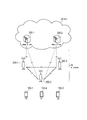
- FIG. 7 is a diagram for explaining an operating environment according to the first embodiment.
- the eNB 200-1 manages the cell 1 (first cell).
- cell 1 UE 100-1C and UE 100-1D are present. That is, cell 1 is a serving cell of each of UE 100-1C and UE 100-1D.
- Each of UE 100-1C and UE 100-1D is in a connected state in cell 1.
- the UE 100-1C performs cellular communication.
- the eNB 200-2 manages the cell 2 (second cell) adjacent to the cell 1.
- UE 100-2C and UE 100-2D are present. That is, cell 2 is the serving cell of each of UE 100-2C and UE 100-2D.
- Each of UE 100-2C and UE 100-2D is in a connected state in cell 2.
- the UE 100-2C performs cellular communication.
- the UE 100-1D transmits a discovery signal (Discovery signal) of a nearby UE (neighboring terminal) that can be a communication partner of D2D communication.
- the UE 100-1D may periodically transmit a discovery signal.
- the discovery signal includes a serving cell identifier that identifies the serving cell of the transmission source UE of the discovery signal. That is, UE 100-1D includes the cell identifier of cell 1, which is its serving cell, as a serving cell identifier in the discovery signal. Further, the UE 100-1D may include the transmission source identifier and / or the transmission destination identifier in the discovery signal.
- the UE 100-2D located in the cell 2 receives the discovery signal from the UE 100-1D.
- the UE 100-2D grasps that the discovery signal transmission source UE (UE 100-1D) is located in the cell 1 based on the serving cell identifier included in the received discovery signal. Then, the UE 100-2D transmits the serving cell identifier included in the discovery signal to the cell 2.
- the UE 100-2D may include the serving cell identifier included in the discovery signal in the Discovery reception report when transmitting the Discovery reception report reporting the reception of the discovery signal to the cell 2.
- the UE 100-2D may include the serving cell identifier included in the discovery signal in the D2D start request.
- the UE 100-2D may include the serving cell identifier included in the discovery signal in the resource allocation request.
- the UE 100-2D simply requests resource allocation (uplink transmission request) from the cell 2 without distinguishing between D2D communication and cellular communication, and the cell 2 (or EPC 20) performs either D2D communication or cellular communication. Determine whether to apply. Note that when the UE 100-2D transmits a resource allocation request (scheduling request), negotiation described later may be omitted.
- UE 100-1D which is a neighboring UE that can be a communication partner of UE 100-2D, is located in cell 1 based on the serving cell identifier received from UE 100-2D. Grasp that. Then, negotiation is performed in cell 1 (eNB 200-1) and cell 2 (eNB 200-2), and scheduling information for controlling D2D communication performed by UE 100-1D and UE 100-2D is shared.
- the scheduling information includes information on radio resources allocated to D2D communication performed by the UE 100-1D and the UE 100-2D.
- the radio resource allocated to the D2D communication performed by the UE 100-1D and the UE 100-2D may be a radio resource allocated (actually) to the D2D communication performed by the UE 100-1D and the UE 100-2D. It may be a radio resource scheduled to be allocated to D2D communication performed by the UE 100-1D and the UE 100-2D (that is, a pre-scheduled radio resource). Alternatively, the radio resource allocated to the D2D communication may be a radio resource allocated to the D2D communication in the cell 1 and / or the cell 2.
- the cell 1 (eNB 200-1) and the cell 2 (eNB 200-2) cooperatively control D2D communication performed by the UE 100-1D and the UE 100-2D based on the shared scheduling information.
- the cell 1 and the cell 2 coordinate the transmission timing of the D2D communication signal. Control.
- the first process and the second process described above are included in the discovery process (Discovery Process) for starting D2D communication.
- the third process and the fourth process are included in the D2D communication process (communication process).
- the cell 1 and the cell 2 can control the D2D communication in cooperation.
- FIG. 8 is a sequence diagram illustrating a specific example of a control procedure according to the first embodiment. The process indicated by the broken line in FIG. 8 indicates that it is not essential.
- the UE 100-1D is a transmitting side in D2D communication
- the UE 100-2D is a receiving side in D2D communication.
- each of the UE 100-1D and the UE 100-2D is in a connected state.
- UE 100-1D transmits a discovery signal including a serving cell identifier (cell identifier of cell 1) (S101-1).
- the UE 100-2D that has received the discovery signal determines whether or not the cell identifier of the cell 2 that is its own serving cell matches the serving cell identifier included in the discovery signal (S102-2). If they do not match, the UE 100-2D transmits the serving cell identifier included in the discovery signal to the cell 2 (S103-2).
- the UE 100-2D may transmit a transmission source identifier (UE identifier of the UE 100-1D) included in the discovery signal to the cell 2.
- the UE 100-2D transmits a discovery signal including the serving cell identifier (cell identifier of the cell 2) (S101-2).
- the UE 100-1D that has received the discovery signal determines whether or not the cell identifier of the cell 1 that is its own serving cell matches the serving cell identifier included in the discovery signal (S102-1). If they do not match, the UE 100-1D transmits the serving cell identifier included in the discovery signal to the cell 1 (S103-1).
- the UE 100-1D may transmit a transmission source identifier (UE identifier of the UE 100-2D) included in the discovery signal to the cell 1.
- the cell 1 reports the serving cell identifier received from the UE 100-1D to the EPC 20 (S104-1).
- Cell 2 reports the serving cell identifier received from UE 100-2D to EPC 20 (S104-2).
- the EPC 20 registers each reported serving cell identifier (S105).
- the cell 1 stores information indicating that the UE 100-2D has been found based on the serving cell identifier (cell identifier of the cell 2) and the transmission source identifier (UE identifier of the UE 100-2D) received from the UE 100-1D. 2 is notified (S106-1). Based on the serving cell identifier (cell identifier of cell 1) and the source identifier (UE identifier of UE 100-1D) received from the UE 100-2D, the cell 2 stores information indicating that the UE 100-1D has been found in the cell 1 Notification is made (S106-2).
- the UE 100-1D transmits a resource allocation request for D2D communication to the cell 1 (S107).
- the resource allocation request may include a communication partner identifier of UE 100-1D (UE identifier of UE 100-2D).
- the cell 1 that has received the resource allocation request from the UE 100-1D inquires of the EPC 20 about the cell identifier of the cell in which the communication partner (UE 100-2D) of the UE 100-1D is located (S108). In response to the inquiry, the EPC 20 notifies the cell 1 of the cell where the communication partner (UE 100-2D) of the UE 100-1D is located (cell identifier of the cell 2) to the cell 1 (S109).
- the cell 1 determines whether or not its own cell identifier matches the cell identifier of the cell in which the communication partner (UE 100-2D) of the UE 100-1D is located (cell identifier of the cell 2) (S110). . If “Yes” in step S102-1, or if the process of S106-1 is being performed, the determination in S110 can be omitted. If they do not match, the cell 1 makes a tentative decision (that is, pre-scheduling) on radio resources to be allocated to D2D communication performed by the UE 100-1D and the UE 100-2D (S111). Then, the cell 1 notifies the cell 2 of scheduling information including information indicating the result of the pre-scheduling (S112).
- the cell 2 that has received the scheduling information from the cell 1 determines whether or not to allow the scheduling information (S113). Then, the cell 2 notifies the determination result to the cell 1 (S114).
- the cell 2 may transmit scheduling information indicating the result of pre-scheduling to the cell 1 itself.
- Cell 1 determines whether scheduling information is permitted in cell 2 (S115). When the cell 1 receives the scheduling information from the cell 2, the cell 1 may determine whether to allow the scheduling information. Here, the description will be made assuming that scheduling information is permitted in the cell 2. In this way, scheduling information is shared between cell 1 and cell 2.
- Cell 1 performs scheduling according to the shared scheduling information (S116-1).
- the scheduling may target only D2D communication, or may target both D2D communication and cellular communication.
- the cell 2 performs scheduling according to the shared scheduling information (S116-2).
- the cell 1 transmits control information indicating transmission permission and allocated radio resources in D2D communication to the UE 100-1D (S117-1).
- the allocated radio resource here is a radio resource used for transmission of the D2D communication signal.
- the cell 2 transmits control information indicating reception permission and allocated radio resources in the D2D communication to the UE 100-2D (S117-2).
- the allocated radio resource here is a radio resource used for receiving the D2D communication signal.
- the radio resource used for receiving the D2D communication signal may be the same as the allocated radio resource transmitted from the cell 1 to the UE 100-1D, or used for receiving the D2D communication signal in the cell 1 and / or the cell 2. It may be a radio resource (reception pool).
- UE 100-1D performs data transmission to UE 100-2D according to the control information received from cell 1 (S118). After receiving data from the UE 100-1D according to the control information received from the cell 2, the UE 100-2D decodes the data. Then, UE 100-2D transmits ACK / NACK indicating success or failure of data decoding to UE 100-1D (S119). The ACK / NACK may be notified to the UE 100-1D via the cell 2 and the cell 1.
- the scheduling information shown in S112 (and S114) in FIG. 8 is transmitted / received on, for example, the X2 interface.
- the scheduling information (D2D scheduling indication) may be an information element of the Load Information message defined in the 3GPP technical specification “TS36.423”.
- the scheduling information may include resource information indicating a frequency resource (resource block) to be allocated to D2D communication and an identifier of a UE to be allocated.
- the resource information is composed of a bit string in which “1” is a resource block to be allocated to D2D communication and “0” is a resource block that is not allocated.
- the scheduling information may include information indicating a time resource (subframe) allocated to D2D communication.
- the scheduling information may include information indicating a modulation / coding scheme (MCS) of D2D communication. Further, the scheduling information may include an identifier for identifying transmission / reception in the D2D communication.
- MCS modulation / coding scheme
- the scheduling information may include a radio resource assigned to D2D communication as described above.
- the radio resource allocated to D2D communication is used for transmission of a D2D communication signal in D2D communication (reception pool; hereinafter referred to as D2D transmission radio resource) and / or D2D communication signal. It is a possible radio resource (hereinafter referred to as D2D reception radio resource).
- the D2D transmission radio resource is within the range of the D2D reception radio resource.
- the information on the radio resources allocated to D2D communication includes, for example, information indicating subframes that can be allocated to D2D communication, and an arrangement pattern of subframes that can be allocated to D2D communication among consecutive subframes (for example, 40 subframes).
- the information on the radio resource allocated to D2D communication includes the resource information indicating the frequency resource (resource block) allocated to D2D communication and the information indicating the time resource (subframe) allocated to D2D communication.
- the scheduling information may include information indicating a spreading code as a radio resource allocated to D2D communication.
- the UE 100-1D is an anchor UE.
- FIG. 9 is a sequence diagram showing an operation pattern 1 of the D2D communication process according to the second embodiment. The process indicated by the broken line in FIG. 9 indicates that it is not essential.
- a procedure (S107 to S116) from when the UE 100-1D transmits a resource allocation request until a radio resource to be allocated to D2D communication is determined is the same as in the first embodiment. .
- the cell 1 transmits control information indicating transmission permission and assignable radio resources in D2D communication to the UE 100-1D (S117-1).
- An allocatable radio resource is an allocation resource block in subframe units, an allocation resource block to which semi-persistent scheduling is applied, or a radio resource dedicated to D2D communication.
- the cell 2 does not transmit control information to the UE 100-2D.
- the UE100-1D which received control information from the cell 1 determines the radio
- UE 100-1D performs data transmission to UE 100-2D using the determined radio resource (S118). After receiving data from UE 100-1D using the allocated radio resource, UE 100-2D decodes the data. Then, UE 100-2D transmits ACK / NACK indicating success or failure of data decoding to UE 100-1D (S119).
- FIG. 10 is a sequence diagram showing an operation pattern 2 of the D2D communication process according to the second embodiment.
- the UE 100-1D performs scheduling for a radio resource or the like desired to be allocated to D2D communication (S301). Also, the UE 100-1D inquires of the cell 1 whether or not the scheduling information determined by itself is applicable (S302).
- the cell 1 determines whether or not its own cell identifier matches the cell identifier of the cell in which the communication partner (UE 100-2D) of the UE 100-1D is located (cell identifier of the cell 2) (S110). . If they do not match, the cell 1 notifies the scheduling information determined by the UE 100-1D to the cell 2 (S112).
- the cell 2 that has received the scheduling information from the cell 1 determines whether to permit the scheduling information (S113). Then, the cell 2 notifies the determination result to the cell 1 (S114).
- the cell 2 may transmit scheduling information indicating the result of pre-scheduling to the cell 1 itself.
- Cell 1 determines whether scheduling information is permitted in cell 2 (S303). When cell 1 receives scheduling information from cell 2, cell 1 may determine whether or not to allow scheduling information from cell 2.
- cell 1 When scheduling information is rejected in cell 2 (and when scheduling information from cell 2 is rejected), cell 1 notifies UE 100-1D of allocation rejection. Here, the description will be made assuming that scheduling information is permitted in the cell 2.
- Cell 1 transmits control information indicating allocation permission (transmission permission) in D2D communication to UE 100-1D (S304). Alternatively, the cell 1 may transmit control information corresponding to the scheduling information from the cell 2 to the UE 100-1D. On the other hand, the cell 2 does not transmit control information to the UE 100-2D.
- the UE 100-1D that has received the control information from the cell 1 transmits control information indicating reception permission and assigned radio resources in D2D communication to the UE 100-2D (S202).
- the UE 100-1D transmits data to the UE 100-2D (S118). After receiving the data from the UE 100-1D, the UE 100-2D decodes the data. Then, UE 100-2D transmits ACK / NACK indicating success or failure of data decoding to UE 100-1D (S119).
- FIG. 11 is a sequence diagram showing an operation pattern 3 of the D2D communication process according to the second embodiment. The process indicated by the broken line in FIG. 11 indicates that it is not essential.
- this operation pattern 3 is a partial modification of the above-described operation pattern 2.
- the control information is transmitted from the UE 100-1D to the UE 100-2D.
- the control information is transmitted from the cell 2 to the UE 100-2D (S401-2).
- the UE 100-1D transmits data to the UE 100-2D (S402). After receiving the data from the UE 100-1D, the UE 100-2D decodes the data. Then, the UE 100-2D notifies the UE 100-1D of ACK / NACK indicating success or failure of data decoding via the cell 2 and the cell 1 (S403 to S405). However, ACK / NACK may be notified directly from UE 100-2D to UE 100-1D.
- the radio signal including the serving cell identifier is a discovery signal, but is not limited thereto.
- the radio signal including the serving cell identifier is a radio signal related to D2D communication.
- the radio signal including the serving cell identifier is a D2D synchronization signal transmitted in a D2D synchronization procedure for establishing synchronization between UEs for D2D communication.
- the radio signal including the serving cell identifier may be a control signal including information (SA: Scheduling Assignment) indicating radio resources used for transmission / reception of user data in D2D communication.
- SA Scheduling Assignment
- wireless resource allocated to D2D communication was a radio
- the radio resource allocated to the D2D communication may be a radio resource (transmission pool / reception pool) that can be used for transmission / reception of the control signal including the above-described SA.
- radio resources that can be used for transmission / reception of control signals including SA may be radio resources (or pre-scheduled radio resources) allocated (actually) to UE 100-1D and UE 100-2D. .
- the cell 1 uses the first radio resource (transmission pool) used for transmission of the D2D communication signal indicating user data as the allocated radio resource.
- a second radio resource that can be used for transmission and reception of control signals including SA.
- the UE 100-1D determines a radio resource for transmitting user data from the first radio resources (scheduling).
- the UE 100-1D transmits a control signal including the SA indicating the determined radio resource using the second radio resource.
- the cell 2 (eNB 200-2) can transmit the second radio resource described above as the allocated radio resource.
- the UE 100-2D can receive the control signal including the SA from the UE 100-1D according to the second radio resource.
- step S118 the UE 100-1D transmits user data using the determined radio resource.
- UE 100-2D receives user data from UE 100-1D according to the SA included in the control signal from UE 100-1D. In this way, the cell 1 and the cell 2 can control the D2D communication of the UE 100-1D and the UE 100-2D in cooperation.
- the eNB 200-1 notifies the eNB 200-2 of the scheduling information, but is not limited thereto.
- the eNB 200-2 may notify the eNB 200-1 of the scheduling information, and the eNB 200-1 (cell 1) and the eNB 200-2 (cell 2) may share the scheduling information.
- the direct communication mode in D2D communication is mainly assumed, but the local relay mode may be applied instead of the direct communication mode.
- the present invention is not limited to the LTE system, and the present invention may be applied to a system other than the LTE system.
- the communication control method, the user terminal, and the base station according to the present invention are useful in the mobile communication field because a plurality of cells can control D2D communication in cooperation.
Landscapes
- Engineering & Computer Science (AREA)
- Computer Networks & Wireless Communication (AREA)
- Signal Processing (AREA)
- Databases & Information Systems (AREA)
- Mobile Radio Communication Systems (AREA)
Abstract
Priority Applications (3)
| Application Number | Priority Date | Filing Date | Title |
|---|---|---|---|
| JP2015501463A JPWO2014129465A1 (ja) | 2013-02-19 | 2014-02-18 | 通信制御方法、ユーザ端末及び基地局 |
| EP14753911.8A EP2961239A4 (fr) | 2013-02-19 | 2014-02-18 | Procédé de commande de communication, terminal utilisateur et station de base |
| US14/767,217 US9826547B2 (en) | 2013-02-19 | 2014-02-18 | Communication control method, user terminal, and base station |
Applications Claiming Priority (2)
| Application Number | Priority Date | Filing Date | Title |
|---|---|---|---|
| US201361766528P | 2013-02-19 | 2013-02-19 | |
| US61/766,528 | 2013-02-19 |
Publications (1)
| Publication Number | Publication Date |
|---|---|
| WO2014129465A1 true WO2014129465A1 (fr) | 2014-08-28 |
Family
ID=51391254
Family Applications (1)
| Application Number | Title | Priority Date | Filing Date |
|---|---|---|---|
| PCT/JP2014/053796 Ceased WO2014129465A1 (fr) | 2013-02-19 | 2014-02-18 | Procédé de commande de communication, terminal utilisateur et station de base |
Country Status (4)
| Country | Link |
|---|---|
| US (1) | US9826547B2 (fr) |
| EP (1) | EP2961239A4 (fr) |
| JP (1) | JPWO2014129465A1 (fr) |
| WO (1) | WO2014129465A1 (fr) |
Cited By (6)
| Publication number | Priority date | Publication date | Assignee | Title |
|---|---|---|---|---|
| WO2017133432A1 (fr) * | 2016-02-04 | 2017-08-10 | Jrd Communication Inc. | Commande de transmission de données directe entre des dispositifs mobiles dans un réseau sans fil |
| EP3229544A4 (fr) * | 2014-12-31 | 2017-12-20 | Huawei Technologies Co. Ltd. | Procédé, dispositif et système de communications |
| JP2018529272A (ja) * | 2015-08-31 | 2018-10-04 | 華為技術有限公司Huawei Technologies Co.,Ltd. | 装置間d2dサービス送信方法、機器、及び装置 |
| CN112040555A (zh) * | 2015-04-10 | 2020-12-04 | 华为技术有限公司 | 数据发送方法和设备 |
| TWI713382B (zh) * | 2015-10-05 | 2020-12-11 | 美商高通公司 | 針對v2x應用的資源配置延遲的最小化 |
| JPWO2022195814A1 (fr) * | 2021-03-18 | 2022-09-22 |
Families Citing this family (7)
| Publication number | Priority date | Publication date | Assignee | Title |
|---|---|---|---|---|
| JP6247022B2 (ja) * | 2013-05-20 | 2017-12-13 | 株式会社Nttドコモ | ユーザ装置、通信システム、及び無線リソース選択方法 |
| US20150078297A1 (en) * | 2013-09-17 | 2015-03-19 | Industrial Technology Research Institute | Method of resource allocation for device to device communication, user equipment using the same and base station using the same |
| US9883513B2 (en) * | 2014-03-19 | 2018-01-30 | Qualcomm Incorporated | Scheduling of device-to-device scheduling assignment for mode1 |
| EP3138333B1 (fr) * | 2014-04-28 | 2021-02-24 | Apple Inc. | Procédé, appareil et système de mesurage de la position d'un équipement utilisateur dans un réseau sans fil |
| WO2016048068A1 (fr) | 2014-09-24 | 2016-03-31 | 엘지전자 주식회사 | Procédé pour émettre un signal de dispositif à dispositif (d2d) et terminal associé |
| US9918266B2 (en) * | 2014-10-06 | 2018-03-13 | Telefonaktiebolaget Lm Ericsson (Publ) | Activation and deactivation of a secondary cell for device-to-device user equipment |
| EP3588992B1 (fr) * | 2017-03-10 | 2024-11-27 | Guangdong Oppo Mobile Telecommunications Corp., Ltd. | Dispositif terminal et procédé de communication |
Citations (3)
| Publication number | Priority date | Publication date | Assignee | Title |
|---|---|---|---|---|
| JP2005203850A (ja) * | 2004-01-13 | 2005-07-28 | Kddi Corp | 移動通信システム、ユーザ端末、中継端末、および中継専用端末 |
| WO2011143496A1 (fr) * | 2010-05-12 | 2011-11-17 | Qualcomm Incorporated | Coordination des ressources pour des groupes poste à poste au moyen d'une négociation distribuée |
| WO2012060934A2 (fr) * | 2010-11-04 | 2012-05-10 | Interdigital Patent Holdings, Inc. | Procédé et appareil permettant d'établir une communication de poste à poste |
Family Cites Families (5)
| Publication number | Priority date | Publication date | Assignee | Title |
|---|---|---|---|---|
| WO2011116815A1 (fr) * | 2010-03-23 | 2011-09-29 | Nokia Siemens Networks Oy | Allocation de ressources pour une communication directe de terminal à terminal dans un système cellulaire |
| US9084259B2 (en) * | 2011-07-18 | 2015-07-14 | Lg Electronics Inc. | Method for maintaining direct device-to-device communication in wireless access system supporting device-to-device communication and apparatus for supporting same |
| GB2496648B (en) * | 2011-11-17 | 2014-04-23 | Broadcom Corp | Method and apparatus for establishing communications |
| US9084241B2 (en) * | 2012-05-21 | 2015-07-14 | Qualcomm Incorporated | Methods and apparatus for determining available resources for D2D communications |
| US9313607B2 (en) * | 2013-01-18 | 2016-04-12 | Telefonaktiebolaget L M Ericsson (Publ) | Network-assisted UE detection in direct mode UE-to-UE communication |
-
2014
- 2014-02-18 JP JP2015501463A patent/JPWO2014129465A1/ja active Pending
- 2014-02-18 WO PCT/JP2014/053796 patent/WO2014129465A1/fr not_active Ceased
- 2014-02-18 US US14/767,217 patent/US9826547B2/en not_active Expired - Fee Related
- 2014-02-18 EP EP14753911.8A patent/EP2961239A4/fr not_active Withdrawn
Patent Citations (3)
| Publication number | Priority date | Publication date | Assignee | Title |
|---|---|---|---|---|
| JP2005203850A (ja) * | 2004-01-13 | 2005-07-28 | Kddi Corp | 移動通信システム、ユーザ端末、中継端末、および中継専用端末 |
| WO2011143496A1 (fr) * | 2010-05-12 | 2011-11-17 | Qualcomm Incorporated | Coordination des ressources pour des groupes poste à poste au moyen d'une négociation distribuée |
| WO2012060934A2 (fr) * | 2010-11-04 | 2012-05-10 | Interdigital Patent Holdings, Inc. | Procédé et appareil permettant d'établir une communication de poste à poste |
Non-Patent Citations (2)
| Title |
|---|
| "TR 22.803 V12.0.0", 3GPP TECHNICAL REPORT, December 2012 (2012-12-01) |
| See also references of EP2961239A4 |
Cited By (10)
| Publication number | Priority date | Publication date | Assignee | Title |
|---|---|---|---|---|
| EP3229544A4 (fr) * | 2014-12-31 | 2017-12-20 | Huawei Technologies Co. Ltd. | Procédé, dispositif et système de communications |
| US10306440B2 (en) | 2014-12-31 | 2019-05-28 | Huawei Technologies Co., Ltd. | Communication method, communications system, and apparatus |
| CN112040555A (zh) * | 2015-04-10 | 2020-12-04 | 华为技术有限公司 | 数据发送方法和设备 |
| JP2018529272A (ja) * | 2015-08-31 | 2018-10-04 | 華為技術有限公司Huawei Technologies Co.,Ltd. | 装置間d2dサービス送信方法、機器、及び装置 |
| US10869171B2 (en) | 2015-08-31 | 2020-12-15 | Huawei Technologies Co., Ltd. | Device-to-device D2D service transmission method, apparatus, and device |
| US11601788B2 (en) | 2015-08-31 | 2023-03-07 | Huawei Technologies Co., Ltd. | Device-to-device D2D service transmission method, apparatus, and device |
| TWI713382B (zh) * | 2015-10-05 | 2020-12-11 | 美商高通公司 | 針對v2x應用的資源配置延遲的最小化 |
| WO2017133432A1 (fr) * | 2016-02-04 | 2017-08-10 | Jrd Communication Inc. | Commande de transmission de données directe entre des dispositifs mobiles dans un réseau sans fil |
| JPWO2022195814A1 (fr) * | 2021-03-18 | 2022-09-22 | ||
| JP7297181B2 (ja) | 2021-03-18 | 2023-06-23 | 三菱電機株式会社 | 中継装置、通信システム、信号中継方法、制御回路および記憶媒体 |
Also Published As
| Publication number | Publication date |
|---|---|
| EP2961239A4 (fr) | 2016-10-12 |
| JPWO2014129465A1 (ja) | 2017-02-02 |
| US9826547B2 (en) | 2017-11-21 |
| US20160007372A1 (en) | 2016-01-07 |
| EP2961239A1 (fr) | 2015-12-30 |
Similar Documents
| Publication | Publication Date | Title |
|---|---|---|
| JP6328132B2 (ja) | 移動通信システム及びユーザ端末 | |
| US9826547B2 (en) | Communication control method, user terminal, and base station | |
| JP6026549B2 (ja) | 移動通信システム、基地局及びユーザ端末 | |
| JP6282705B2 (ja) | ユーザ端末、プロセッサ及び通信制御方法 | |
| WO2014017476A1 (fr) | Système de communication mobile, station de base, dispositif utilisateur et processeur | |
| WO2015125716A1 (fr) | Système de communication de corps mobile, station de base, et terminal d'utilisateur | |
| WO2014157398A1 (fr) | Procédé de commande de communication et processeur | |
| US20170150503A1 (en) | Communication control method, radio communication apparatus, and resource management apparatus | |
| JP6140292B2 (ja) | ネットワーク装置及びユーザ端末 | |
| WO2014017477A1 (fr) | Système de communication mobile, dispositif utilisateur et processeur | |
| JPWO2015046272A1 (ja) | ユーザ端末、ネットワーク装置及びプロセッサ | |
| JP6200078B2 (ja) | ユーザ端末、プロセッサ及び方法 | |
| JP6302129B1 (ja) | 基地局及びプロセッサ | |
| JP6140014B2 (ja) | ユーザ端末、基地局、及びプロセッサ | |
| JP6034956B2 (ja) | 移動通信システム、基地局及びユーザ端末 | |
| JP6398032B2 (ja) | 移動通信システム、ユーザ端末、基地局、及びプロセッサ | |
| WO2015005244A1 (fr) | Terminal utilisateur, dispositif de réseau et processeur | |
| JP6140013B2 (ja) | 移動通信システム、ユーザ端末、ネットワーク装置及びプロセッサ | |
| JP2015159490A (ja) | 通信制御方法及び基地局 |
Legal Events
| Date | Code | Title | Description |
|---|---|---|---|
| 121 | Ep: the epo has been informed by wipo that ep was designated in this application |
Ref document number: 14753911 Country of ref document: EP Kind code of ref document: A1 |
|
| ENP | Entry into the national phase |
Ref document number: 2015501463 Country of ref document: JP Kind code of ref document: A |
|
| WWE | Wipo information: entry into national phase |
Ref document number: 14767217 Country of ref document: US |
|
| NENP | Non-entry into the national phase |
Ref country code: DE |
|
| REEP | Request for entry into the european phase |
Ref document number: 2014753911 Country of ref document: EP |
|
| WWE | Wipo information: entry into national phase |
Ref document number: 2014753911 Country of ref document: EP |