WO2014129645A1 - 液状物繰出容器 - Google Patents
液状物繰出容器 Download PDFInfo
- Publication number
- WO2014129645A1 WO2014129645A1 PCT/JP2014/054430 JP2014054430W WO2014129645A1 WO 2014129645 A1 WO2014129645 A1 WO 2014129645A1 JP 2014054430 W JP2014054430 W JP 2014054430W WO 2014129645 A1 WO2014129645 A1 WO 2014129645A1
- Authority
- WO
- WIPO (PCT)
- Prior art keywords
- piston
- screw
- rod
- shaft
- liquid
- Prior art date
- Legal status (The legal status is an assumption and is not a legal conclusion. Google has not performed a legal analysis and makes no representation as to the accuracy of the status listed.)
- Ceased
Links
Images


Classifications
-
- A—HUMAN NECESSITIES
- A45—HAND OR TRAVELLING ARTICLES
- A45D—HAIRDRESSING OR SHAVING EQUIPMENT; EQUIPMENT FOR COSMETICS OR COSMETIC TREATMENTS, e.g. FOR MANICURING OR PEDICURING
- A45D34/00—Containers or accessories specially adapted for handling liquid toiletry or cosmetic substances, e.g. perfumes
- A45D34/04—Appliances specially adapted for applying liquid, e.g. using roller or ball
- A45D34/042—Appliances specially adapted for applying liquid, e.g. using roller or ball using a brush or the like
-
- A—HUMAN NECESSITIES
- A45—HAND OR TRAVELLING ARTICLES
- A45D—HAIRDRESSING OR SHAVING EQUIPMENT; EQUIPMENT FOR COSMETICS OR COSMETIC TREATMENTS, e.g. FOR MANICURING OR PEDICURING
- A45D2200/00—Details not otherwise provided for in A45D
- A45D2200/05—Details of containers
- A45D2200/054—Means for supplying liquid to the outlet of the container
- A45D2200/055—Piston or plunger for supplying the liquid to the applicator
Definitions
- the present invention is a liquid material in which liquid materials such as liquids and fluids (liquid materials) such as cosmetics and chemicals are accommodated in the accommodating portion of the shaft main body, and the liquid material accommodated by the feeding operation of rotating the tail end is sent to the application body. It relates to a feeding container.
- Patent Document 1 a piston moves forward by an operation of rotating the tail end, and the liquid material in the shaft body can be discharged. ing.
- this liquid material supply container the ratio of the supply mechanism portion including the piston in the shaft main body is high, and a large amount of liquid material cannot be accommodated.
- Patent Document 2 an applicator capable of extending the piston in two stages and increasing the liquid volume as disclosed in JP 2007-143857 A (: Patent Document 2) is disclosed.
- both the shaft cylinder and the piston are formed with irregularities that are anti-rotation members for sliding.
- the liquid material supply container of Patent Document 1 is provided with a concave portion in the shaft body and a convex portion in the rear portion of the piston so that it cannot be rotated inadvertently by the rotational force of the piston in the rotating direction of the rotating body.
- Patent Document 2 uses an uneven rotation-preventing shape between the members and uses many screwing members, which may complicate the mold processing and make it difficult to stabilize the molded member.
- the present invention provides a liquid material supply container which can be configured at low cost with no problems in the operation of extending the piston, the liquid volume in the shaft cylinder being increased, and the number of parts being small and the die processing being easy. This is the issue.
- the liquid content is accommodated in the accommodating portion provided in the shaft main body, and the piston is advanced in the accommodating portion by rotating the operation portion of the rotating body exposed from the rear end portion of the shaft main body relative to the shaft main body.
- the piston has a seal part at the front that is in sliding contact with the inner wall of the housing part of the shaft body, and a rod member having a screw part on the inner periphery or outer periphery is movable in the axial direction and is restricted in the rotational direction.
- the front rod-like portion extending forward from the operation portion is formed with a screw portion that is directly or indirectly screwed with the screw portion of the rod member at the rear of the piston,
- a liquid feed container characterized in that the piston is advanced by performing an operation of rotating the operation portion relative to the shaft body, and the front bar-like portion is configured to be extendable and retractable in multiple stages after the advancement.
- the rod member at the rear part of the piston is movable in the front-rear direction with respect to the inner wall of the housing part together with the seal part, and is regulated in the rotational direction, and the outer peripheral surface of the front seal part of the piston is It is preferable that the inner wall of the housing portion is slidably contacted and movable in the axial direction, and is held so as not to be easily rotated by the sliding contact force in the rotational direction.
- the piston is in sliding contact with an appropriate tightening allowance to prevent leakage of liquid contents, with the seal portion at the front thereof being in sliding contact with the inner wall of the shaft main body accommodating portion. It is preferable that the slidable contact force is held so as not to be easily rotated in the circumferential direction.
- the rod member at the rear of the piston is formed with a threaded portion on the outer periphery or inner periphery, and the rod member threaded portion at the rear of the piston is attached to the front rod-shaped portion extending forward from the operation portion of the rotating body.
- a screw portion that is directly or indirectly screwed is formed, and a screw member that does not have a screw shape is provided at one end of the rod member and the front rod-like portion that are screwed together. Is preferred.
- the rod member at the rear of the piston has a threaded portion formed on the outer periphery or the inner periphery, and the rod member screw at the rear of the piston extends to the front rod-shaped portion extending forward from the operation portion of the rotating body. It is preferable that a screw part that is directly or indirectly screwed with the part is formed, and a slit for dividing the screw part is provided at one end of the front bar-like part of the rotating body.
- the slit is preferably provided close to the inner peripheral surface of the shaft body.
- an elastic body is provided between the rotating body and the front bar-shaped portion.
- the front rod-like portion extending forward from the operation portion is formed with a screw portion that is directly or indirectly screwed with the screw portion of the rod member at the rear of the piston,
- the piston rod member moves forward, and after the advancement, the front rod-shaped portion is configured to be able to expand and contract in multiple stages. Further advancement is made not only by the length but also by the advancement of the front rod-like portion, so that the feeding amount of the liquid material can be set to a feeding amount that is longer than the length of the piston rod member, and the liquid material accommodation amount of the housing portion is increased. It is possible to achieve an excellent effect of being able to. Further, by providing the elastic body between the inner surface of the rotating body and the front bar-shaped portion, a large feeding torque generated at the start of feeding can be reduced and the feeding can be easily performed.
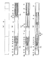
- 1 to 6 are explanatory views of a liquid material feeding container according to the first embodiment of the present invention.
- FIG. 1 is an explanatory view of a liquid material supply container according to the first embodiment in a state where a cap is removed
- FIG. 2 is a state where the cap is removed.
- the liquid material supply container accommodates the liquid material in the accommodating portion 12 provided in the shaft main body 10, and the operation portion 16 of the rotating body 14 exposed from the rear end portion of the shaft main body 10.
- This is a liquid material supply container that advances the piston 18 in the accommodating portion 12 by rotating relative to the shaft body 10 and supplies the liquid material toward the application body 20 ahead of the shaft body 10.
- the tip 22 of the shaft body 10 is detachable from the cap 22, and when the liquid material supply container is not used, the tip 22 is covered by the cap 22 as shown in FIG. In use, the cap 22 is removed and the applicator 20 is fed out.
- the liquid material supply container has a seal ball receiver 24, a pipe joint 26, a pipe 28, a tip shaft 30, and an application body 20 attached to the tip portion 10 a of the shaft body 10.
- the delivered liquid material is discharged to the tip of the application body 20 through the pipe 28.
- the tip portion 10a of the shaft body 10 has a diameter that is thinner than the central portion, and a cylindrical seal ball receiver 24 is fitted inside the tip portion 10a.
- a seal ball (not shown) is fitted in the rear part of the seal ball receiver 24, and a pipe joint 26 is attached to the front part.
- a pipe 28 is attached to the pipe joint 26 in the front, and the pipe 28 is inserted into the application body 20 made of a brush from the rear part.
- the hollow communication paths of the pipe joint 26 and the pipe 28 communicate with the application body 20, and when the seal ball is fitted in the seal ball receiver 24, the communication between the hollow communication path and the housing portion 12 is closed by the seal ball. .
- the seal ball receiver 24 is provided with a seal ball locking structure (not shown). When the seal ball receiver 24 is used, the seal ball is dropped into the housing portion 12 by removing the lock structure, and the liquid material passes through the pipe joint 26 and the pipe 28. So as to be supplied to the application body 20.
- the front shaft 30 covers the periphery of the pipe 28, the pipe joint 26 and the seal ball receiver 24 from the rear portion of the application body 20, and the front shaft 30 whose diameter is reduced in a tapered shape is fitted to the distal end portion 10 a of the shaft body 10.
- the inner peripheral surface of the tip shaft 30 and the outer peripheral surface of the distal end portion 10a of the shaft body 10 are closely fitted to form a stopper (see FIGS. 1 and 2).
- the cap 22 including the inner cap 22a and the inner cap spring 22b can be attached.
- the cap 22 is mounted so as to cover the front shaft 30, and the inner cap 22a covers the periphery of the front shaft 30 and the application body 20 by the urging force of the inner cap spring 22b to maintain the airtightness of the application body 20. It is intended to prevent drying.
- the seal ball when the applicator is not used, the seal ball is fitted in the seal ball receiver 24, and when the use is started, the seal ball is dropped into the storage unit 12 so that the storage unit 12 and the pipe 28 are in a circulation state.
- bowl can be stirred by arrange
- the piston 18 has a seal portion 32 (outer periphery) at the front thereof in sliding contact with the inner wall of the accommodating portion 12 of the shaft body 10, and a rod member 34 having a screw portion on the inner periphery or outer periphery at the rear portion is movable in the axial direction. The rotation direction is restricted.
- the front rod-like portion 36 extending forward from the operation portion 16 is formed with a screw portion that is directly screwed with the screw portion of the rod member 34 at the rear portion of the piston 18.
- the front rod-like portion 36 of the rotating body 14 is provided with a thick cylindrical body that is screwed into the inside of the front portion of the operation portion 16 and extends forward, and this front rod-like portion.
- a threaded portion 38 (a threaded portion 38b of an internal thread) is formed on the threaded portion 36 of the rod member 34 at the rear portion of the piston 18.
- the front rod-like portion 36 that is screwed into the rotating body 14 is formed with screw portions 38 (a male screw portion 38a and a female screw portion 38b) on the inner and outer surfaces.
- screw portions 38 a male screw portion 38a on the outer peripheral surface screwed with the screw portion 14b made of the female screw is formed, and a female screw 38b screwed with the screw portion 34a of the bar member 34 is formed on the inner surface.
- a threaded portion 38 a made of an external thread on the outer periphery of the front rod-shaped portion 36 is formed continuously from the front end portion of the front rod-shaped portion 36 to the vicinity of the rear end portion.
- the rear end portion of the front bar-shaped portion 36 is a non-formed portion 38c where no thread is formed.
- a slit for dividing the screw may be formed in the screw portion 14b of the rotating body 14 (the slit portion 14c is formed in the screw portion 14b in a third embodiment described later (see FIG. 12). explain).
- the screw portion 14 b of the rotating body 14 (operation portion 16) is indirectly screwed to the screw portion 34 a of the rod member 34 via the screw portion 38 of the front rod-like portion 36. Yes.
- the sliding frictional force of the threaded portion 34a of the rod member 34 fixed to the piston 18 to the inner threaded portion 38b of the front rod-shaped portion 36 is such that the outer threaded portion 38a of the front rod-shaped portion 36 is a rotating body. It is set to be smaller than the sliding frictional force screwed into the 14 screw portions 14b.
- the rod member 34 of the piston 18 moves forward from the difference of the sliding frictional force by performing an operation of rotating relative to the shaft body 10 of the operation unit 16 from the state shown in FIG. 32 moves forward. Since the rod member 34 is locked to the front rod-like portion 36 in the state shown in FIG. 2 (c) after the piston 18 has moved forward, when the operation portion 16 is further rotated, the front rod-like portion 36 is attached to the rotating body 14.
- a structure that can be extended and contracted in multiple stages is provided by a mechanism that is extended and advanced to further advance the seal portion 32.
- the rotary body 14 is formed in the hollow and has opened the tail end, it is possible to improve the design by inserting a stopper so that the inside is not visible.
- the piston 18 has a structure in which the seal portion 32 and the rod member 34 are connected.
- the bar member 34 is a screw portion 34 a in which a thread is formed on the outer peripheral surface of substantially the entire central portion excluding the front end and the rear end.
- an engaging portion 34b with the seal portion 32 is formed in an irregular shape at the front end of the bar member 34, and a non-formed portion 34c in which no thread is formed is formed at the rear end.
- the engaging portion 34b is thin in the axial direction and is substantially shield-shaped.
- the seal portion 32 has a generally cup-shaped or wheel-shaped rotating body shape, and the front and rear ends of the outer peripheral surface thereof are formed to have a diameter larger than the center, and the outer peripheral surface has two circumferential directions.
- the seal surface formed along the slidable contact with the inner wall of the housing portion 12 of the shaft body 10 is configured.
- the seal portion 32 is formed such that an engaged portion 32a protrudes rearward in a cylindrical shape rearward from the internal hub-like portion.
- the engaged portion 32a is an engagement structure such as a hook structure in which a protruding cylindrical portion is formed with a cut on the side surface. From this cut, an engagement portion 34b (shown in FIG. 3) of the bar member 34 is formed. ) Is inserted and attached, the seal portion 32 and the rod member 34 are fixed in the rotational direction and the front-rear direction, and move back and forth as an integral piston 18.
- the rotating body 14 has a substantially hollow cylindrical shape, and the outer periphery has a larger diameter at the rear than the front, and is an operation unit 16 that can be picked and rotated by the user.
- An annular rib is formed on the outer peripheral surface of the front portion so as to have a fitting portion 14a that engages the shaft body 10 rotatably and prevents it from coming off.
- a screw portion 14b of a female screw is formed at the front.
- rod member 34 at the rear of the piston 18 is movable in the front-rear direction with respect to the inner wall of the accommodating portion 12 together with the seal portion 32 and is restricted in the rotational direction.
- the regulation of the rotational direction of the piston 18 is such that the outer peripheral surface of the seal portion 32 at the front portion of the piston 18 is in sliding contact with the inner wall of the housing portion 12 of the shaft body 10 and is movable in the axial direction. Is held so as not to be easily rotated by the sliding contact force. That is, the piston 18 is in sliding contact with an appropriate margin to prevent the liquid content from leaking when the front seal portion 32 is in sliding contact with the inner wall of the housing portion 12 of the shaft body 10. It is held so as not to be easily rotated in the circumferential direction by the sliding contact force generated by.
- Each part such as the piston 18 is resin-molded, and the tightening margin is adjusted by setting the dimensions thereof, and the material can be easily rotated by selecting a material.
- the threaded portion 34a of the rod member 34 fixed to the piston 18 is screwed into the inner threaded portion 38b of the front rod-shaped portion 36, and the outer threaded portion 38a of the front rod-shaped portion 36 is threaded to the threaded portion 14b of the rotating body. Match.
- the piston 18 is located at the retreat limit, and the accommodating portion 12 has the maximum volume.
- the operation unit 16 is picked and the rotating body 14 is rotated with respect to the shaft body 10.
- the rod member 34 of the piston 18 advances and the seal portion 32 advances due to the difference in the sliding frictional force. Go forward.
- the non-formed portion 34c without the threaded portion 34a comes into contact with the inner threaded portion 38b of the front rod-shaped portion 36, so that a fixed state with respect to the front rod-shaped portion 36 and a locked state where it does not advance further.
- the forward limit is shown in FIG.
- the outer male screw portion 38a is screwed with the female screw 14b of the rotating body 14, and therefore, as shown in FIG. Is fed to the rotating body 14 and moves forward to further advance the seal portion 32.
- the non-formed portion 38c of the screw portion 38 abuts against the female screw 14b of the rotating body 14, it does not advance any further, and the piston 18 can be prevented from being pushed too much.
- the liquid material delivery container is configured such that the rod member 34 and the front rod-like portion 36 of the piston 18 can be expanded and contracted in multiple stages with respect to the rotating body 14.
- the present invention is not limited to the configuration of the liquid material supply container according to the first embodiment, and can be variously modified.
- a liquid material supply container according to a second embodiment of the present invention will be described with reference to FIGS.
- the same parts as those in the first embodiment are denoted by the same reference numerals.
- the piston 18 is formed by integrally resin-molding the front seal part 32 and the rear bar member 34. Since the rod member 34 having a threaded portion on the outer periphery is integral, it can be moved in the axial direction like the piston 18 and is restricted in the rotational direction.
- the non-formed part 34c is not formed with a screw, and therefore, when assembled to the front rod-like part 36, a slit is formed in the female screw 38b so as to be divided or not formed.
- the part 34c may have a slit, or both may have a slit.
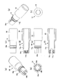
- the application body 20 has a substantially conical shape, and a plurality of disk portions (flange-like portions) protruding outward are concentrically arranged at predetermined intervals from the front end to the rear end.
- the application body 20 is used to apply a liquid such as mascara, and has a structure that can be easily applied to the eyelashes or the like by the protrusions of the disk portion and can be sufficiently applied.
- the periphery of the application body 20 is covered with a tip shaft and fitted into the tip portion 10 a of the shaft body 10.
- FIGS. 10 is a non-use state in which a cap is provided
- FIG. 11 is a use state in which the cap is removed
- FIG. 12 is an explanatory view of a rotating body
- FIG. 13 is a vertical cross-sectional explanatory view of a rear portion of a liquid material supply container.
- the piston 18 has a structure in which the seal portion 32 and the rod member 34 are connected in the same manner as in the first embodiment. Further, as shown in FIG. 10, the cap 22 is fitted when not in use, and the cap 22 is removed when in use as shown in FIG. Before the piston 18 is extended, the state shown in FIG. 10A and FIG. 11A is obtained. Before the piston 18 is extended, the state shown in FIG. 10B and FIG. The limit is as shown in FIG. 10 (c) and FIG. 11 (c).
- the rotating body 14 has a substantially hollow cylindrical shape, the outer periphery is larger in the rear than the front, and the operation unit 16 that can be picked and rotated by the user. It has become.
- a rib is formed on the outer peripheral surface of the front portion in an annular shape of a fitting portion 14a that rotatably engages and prevents the shaft body 10 from coming off.
- a screw portion 14b of a female screw is formed at the front portion.
- a slit for dividing the screw portion is provided at one end of the front rod-like portion of the rotating body 14.
- segments the screw part 14b is formed in the part ahead of the one part operation part 16 of the rotary body 14 at the part to which the front bar-shaped part 36 is screwed. That is, a slit 14c is formed in the front portion of the rotating body 14 by cutting backward from the front end so as to cut the formation portion of the screw portion 14b at two pairs of radial positions.
- the front portion of the rotating body 14 is slightly enlarged in diameter from the slit 14c when the front rod member 36 is assembled, and the front rod-like portion 36 can be gently screwed. Further, it is possible to press-fit the front bar member 36 as it is by expanding the diameter from the slit 14c.
- the slit 14c can be provided close to the inner peripheral surface (indicated by reference numeral 10b) of the shaft body 10.
- interval (delta) of the slit 14c and the internal peripheral surface 10b is 0.5 mm or less. This interval can be selected and implemented as appropriate.
- a liquid material supply container according to the fourth embodiment of the present invention will be described with reference to FIG.
- the same parts as those in the first embodiment are denoted by the same reference numerals.
- this liquid material supply container is provided with a rear cylinder member 40 that is screwed into the outer periphery of the front bar-like portion 36 and screwed into the inner periphery of the screw portion 14 b of the rotating body 14.
- An elastic body (spring) 42 is provided between the front bar portion 36 and the rotating body 14.
- This liquid material supply container has a structure in which the elastic body 42 urges the front rod-shaped portion 36 forward, so that as shown in FIGS.
- the piston 18 can be advanced not only by the forward force but also by the forward force via the front rod-like portion 36 by the pressing force of the projectile 42.
- a substantially cup-shaped spring that is open at the front and closed at the rear to receive the rear end of the elastic body 42 in the roughly cylindrical rotating body 14.
- a receiver 44 is provided so as to close the rear opening of the rotating body 14.
- a rear cylindrical member 40 is disposed coaxially between the rotating body 14 and the front bar-shaped portion 36.
- the rear cylinder member 40 has screws (internal and external threads) formed on the inner and outer peripheral surfaces.
- a male screw is formed on the outer peripheral surface over the front and back, and a female screw is formed on the inner peripheral surface with a small front portion, and a rear portion from the rear end of the female screw via a stepped portion. Then, the diameter is increased and formed on a flat inner surface without screws.
- the inner thread portion 14b of the rotating body 14 is screwed into the outer thread of the rear cylindrical member 40, and the outer male thread 38a of the front rod-shaped portion 36 is The member 40 is screwed into the female screw on the inner peripheral surface.
- the piston 18 is configured such that the front seal portion 32 is coupled to the front end of the rear rod portion 34 by screwing a screw inserted from the front.
- the piston 18 may have a structure in which a seal portion 32 and a rod-like portion 34 are coupled as shown in FIG. 1 which is the first embodiment and FIG. 10 which is the third embodiment. Or it is good also as a structure with which the seal
- the rear portion of the rear cylinder member 40 is provided so that a spring 42 accommodated in the spring receiver 44 can be received and presses the rear cylinder member 40 forward.
- the feeding torque to the piston 18 can be applied by the pressing force of the elastic body 42 together with the rotational force of the rotating body 14.
- the coating liquid can be applied with a light rotational force. This is because, when the outer diameter of the screw of the rotating body 14 is increased without the rear cylindrical member 40 and the elastic body 42 being provided, the inner diameter of the screw portion 14b of the rotating body 14 and the front rod-like portion 36 that is screwed to the inner diameter.
- the user can quickly feed out the contents with a smaller number of rotary feeding operations when starting to use, and the feeding operation can be rotated by increasing the screw pitch.
- the force increases, the liquid material can be quickly delivered with a light force by the assistance of the projectile 42.
- the two-stage piston 18 can be driven forward and forward by the rod member 34, the front rod-shaped portion 36, and the rotating body 14. It is also possible to provide a plurality of front bar portions so that they can be driven out in three or more stages.
- the rod member, the front rod-shaped portion, the male thread of the threaded part of the rotating body, and the female thread can be set to other settings.
- a structure can be adopted in which a rod member is hollowed and a front rod-like portion is screwed therein, and a rod-like male screw is screwed into the front rod-like portion from a rotating body.
- liquid materials such as oral cleansing agents, drugs, etc. are accommodated in the accommodating portion of the shaft body, and are accommodated by a feeding operation that rotates the tail end.
- SYMBOLS 10 Shaft main body 10a Tip part 12 Storage part 14 Rotating body 14a Fit part 14b Screw part 16 Operation part 18 Piston 18b Engagement part 20 Application body 22 Cap 30 Lead shaft 32 Seal part 32a Engagement part 34 Bar member 34a Screw Part 34b engaging part 34c non-forming part 36 front rod-like part 38 screw part 38a outer male screw 38b inner female screw 40 rear cylinder member 42 elastic body
Landscapes
- Containers And Packaging Bodies Having A Special Means To Remove Contents (AREA)
- Pens And Brushes (AREA)
Abstract
ピストン(18)の繰出動作に問題が無く、軸筒内での液容量を増やすことが可能かつ、部品点数が少なく金型加工が容易な低コストで構成できる液状物繰出容器を提供する。ピストン(18)は、その前部のシール部(32)が軸本体の収容部内壁に摺接し、その後部には内周或いは外周にネジ部を有する棒部材(34)が軸線方向に移動可能で回転方向には規制されて配置され、前記操作部から前方に延びた前部棒状部(36)には、前記ピストン後部の棒部材(34)のネジ部に直接または間接的に螺合するネジ部が形成されており、前記操作部を軸本体(10)と相対回転させる操作をすることにより、前記ピストン(18)が前進し、前進後に前部棒状部(36)が多段階に伸縮可能に構成されている液状物繰出容器。
Description
本発明は、液体や流動体(液状物)の化粧料や薬品等の液状物を軸本体の収容部内に収容し、尾端を回転させる繰出し操作によって収容した液状物を塗布体に送り出す液状物繰出容器に関する。
従来、特開2010-227553号公報(:特許文献1)に代表される液状物繰出容器においては、尾端を回転する繰出操作によってピストンが前進し、軸本体内の液状物を吐出可能となっている。しかし、この液状物繰出容器においては、ピストンを含む繰出機構部が軸本体内に占める割合が高く、多くの液状物の収容をすることができない。
そこで、特開2007-143857号公報(:特許文献2)のようにピストンを二段階に繰出して液容量を増やすことができる塗布具が開示されている。
上記の特許文献1、2は、共に軸筒とピストンとの摺動は回り止め部材である凹凸が形成されている。
特に、特許文献1の液状物繰出容器は、軸本体に凹部、ピストンの後方部に凸部を設け回転体繰出操作時においてピストンの回転方向の回転力によって不用意に回転できないようにしている。
しかしながら、特許文献1の技術では、軸本体の凹部はピストンの移動距離同等かそれ以上に軸線方向に長く形成しておく必要があり、かつ、軸断面も均等肉厚でないため成形時の後収縮で変形(歪)しやすいことや、金型加工上も高価格になる傾向にあった。
また、特許文献2の塗布具では、各部材間に凸凹の回り止め形状を用い、多くの螺合部材を使用しており、金型加工を複雑にし、成形部材の安定性を難しくさせる可能性も秘め、組立性の煩雑さを想定させるなど高コストな容器形態であることをうかがわせていた。
そこで、本発明はピストンの繰出動作に問題が無く、軸筒内での液容量を増やすことが可能かつ、部品点数が少なく金型加工が容易な低コストで構成できる液状物繰出容器を提供することを課題とする。
本発明は、軸本体に設けた収容部内に液状の内容物を収容し、軸本体後端部から露出した回転体の操作部を軸本体と相対回転することにより収容部内でピストンを前進させて、該内容物を軸本体先方に向けて繰出す液状物繰出容器において、
ピストンは、その前部のシール部が軸本体の収容部内壁に摺接し、その後部には内周或いは外周にネジ部を有する棒部材が軸線方向に移動可能で回転方向には規制されて配置され、
前記操作部から前方に延びた前部棒状部には、前記ピストン後部の棒部材のネジ部に直接または間接的に螺合するネジ部が形成されており、
前記操作部を軸本体と相対回転させる操作をすることにより、前記ピストンが前進し、前進後に前部棒状部が多段階に伸縮可能に構成されていることを特徴とする液状物繰出容器である。
ピストンは、その前部のシール部が軸本体の収容部内壁に摺接し、その後部には内周或いは外周にネジ部を有する棒部材が軸線方向に移動可能で回転方向には規制されて配置され、
前記操作部から前方に延びた前部棒状部には、前記ピストン後部の棒部材のネジ部に直接または間接的に螺合するネジ部が形成されており、
前記操作部を軸本体と相対回転させる操作をすることにより、前記ピストンが前進し、前進後に前部棒状部が多段階に伸縮可能に構成されていることを特徴とする液状物繰出容器である。
本発明において、前記ピストン後部の棒部材が、シール部と共に収容部内壁に対して前後方向に移動可能で回転方向に規制され、前記ピストンは、その前部のシール部の外周面が軸本体の収容部内壁に摺接し、軸線方向に移動可能であり、かつ、回転方向にはその摺接力によって容易に回転されないよう保持されていることが好適である。
また、本発明において、ピストンは、その前部のシール部が軸本体収容部の内壁に摺接し、液状の内容物の漏出を防止するため適宜な締め代を持って摺接し、その締め代によって発生した摺接力によって円周方向に容易に回転されないよう保持されていることが好適である。
本発明において、前記ピストン後部の棒部材は外周或いは内周にネジ部が形成され、前記回転体の前記操作部から前方に延びた前部棒状部には、前記ピストン後部の棒部材ネジ部に直接又は間接的に螺合するネジ部が形成されており、互いのネジ部が螺合する棒部材及び前部棒状部のいずれかの一端にネジ形状のないネジ不形成部を設けたことが好適である。
また、本発明において、前記ピストン後部の棒部材は外周或いは内周にネジ部が形成され、前記回転体の前記操作部から前方に延びた前部棒状部には、前記ピストン後部の棒部材ネジ部に直接又は間接的に螺合するネジ部が形成されており、前記回転体の前部棒状部の一端に、ネジ部を分断するスリットが設けられていることが好適である。
本発明において、スリットは、軸本体の内周面に近接して設けられていることが好適である。
また、本発明において、前記回転体と前部棒状部との間に弾発体を設けられていることが好適である。
本発明の液状物繰出容器によれば、操作部から前方に延びた前部棒状部には、ピストン後部の棒部材のネジ部に直接または間接的に螺合するネジ部が形成されており、前記操作部の軸本体と相対回転する操作をすることにより、前記ピストン棒部材が前進し、前進後に前部棒状部が多段階に伸縮可能に構成されているので、ピストンの前進が棒部材の長さのみならず前部棒状部の前進によってさらに前進するため、液状物の繰出し量がピストン棒部材の長さ以上の繰出し量とすることができ、収容部の液状物収容量を多くすることができるという優れた効果を奏し得る。
また、回転体の内面と前部棒状部との間に弾発体を設けることで、繰出し開始時に発生する大きい繰出しトルクを低減し、容易に繰出すことができる。
また、回転体の内面と前部棒状部との間に弾発体を設けることで、繰出し開始時に発生する大きい繰出しトルクを低減し、容易に繰出すことができる。
以下、本発明の実施形態について添付図面を参照して説明する。
図1~図6は本発明の第1実施形態に係る液状物繰出容器の説明図である。
図1~図6は本発明の第1実施形態に係る液状物繰出容器の説明図である。
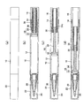
図1はキャップをした状態、図2はキャップを外した状態の第1実施形態に係る液状物繰出容器の説明図である。
図1、図2に示すように、液状物繰出容器は、軸本体10に設けた収容部12内に液状物を収容し、軸本体10後端部から露出した回転体14の操作部16を軸本体10と相対回転することにより収容部12内でピストン18を前進させて、該液状物を軸本体10先方の塗布体20に向けて繰出す液状物繰出容器である。
軸本体10の先端部は、キャップ22が着脱自在であって、液状物繰出容器の不使用時には、図1のようにキャップ22によって当該先端部を覆って塗布体20の液状物の乾燥を防止し、使用時にはキャップ22を外して塗布体20が繰出しされようになっている。
前記液状物繰出容器は、図1に示すように、軸本体10の先端部10aにシールボール受け24、パイプ継手26、パイプ28、先軸30、塗布体20が取付けられ、収容部12からの繰出しされた液状物は、パイプ28を通り塗布体20先端に吐出されるようになっている。
軸本体10の先端部10aは中央部よりも段状に細い径になっていて、先端部10a内部に筒状のシールボール受け24が嵌入している。このシールボール受け24の後部に図視しないシールボールが嵌入し、また前部にパイプ継手26が装着されている。パイプ継手26には前方にパイプ28が装着されており、このパイプ28が筆穂からなる塗布体20にその後部から差し込まれている。
パイプ継手26、パイプ28の中空連通路は塗布体20に連通し、シールボールがシールボール受け24に嵌入した状態では、シールボールによって上記中空連通路は収容部12との連通が閉鎖されている。シールボール受け24には図示しないシールボールの係止構造が設けられ、使用開始時にその係止構造を外すことによってシールボールを収容部12内に落とし込んで液状物がパイプ継手26及びパイプ28を介して塗布体20に供給されるようにしている。
先軸30は、前記塗布体20の後部からパイプ28、パイプ継手26及びシールボール受け24周囲を覆って、先端テーパー状に縮径する先軸30が前記軸本体10の先端部10aに嵌着されている。先軸30の内周面と軸本体10の先端部10aの外周面には、緊密に嵌合し抜け止めが形成されている(図1、図2参照)。
また、塗布具の使用後には、図1に示すように、インナーキャップ22a、インナーキャップスプリング22bを備えたキャップ22を装着できるように形成されている。キャップ22使用時には、先軸30を覆ってキャップ22を装着し、インナーキャップ22aはインナーキャップスプリング22bの付勢力によって先軸30及び塗布体20周囲を覆って塗布体20の気密性を保持して乾燥を防止するものになっている。
さらに、塗布具の未使用時には、シールボールがシールボール受け24に嵌合しており、使用開始時にシールボールを収容部12内に落とし込んで、収容部12とパイプ28とを流通状態とする。なお、収容部12内に攪拌ボールを配して、液状物繰出容器を上下に振ることで内容物の液状物の攪拌を行うことができる。
ピストン18は、その前部のシール部32(外周)が軸本体10の収容部12内壁に摺接し、その後部には内周或いは外周にネジ部を有する棒部材34が軸線方向に移動可能で回転方向には規制されて配置されている。
操作部16から前方に延びた前部棒状部36には、前記ピストン18後部の棒部材34のネジ部に直接的に螺合するネジ部が形成されている。
第1実施形態では、回転体14の前部棒状部36は、前記操作部16前方の部分の内側に螺合して前方に延びた太筒体を設けたものであり、この前部棒状部36に、前記ピストン18後部の棒部材34のネジ部34aに螺合するネジ部38(雌ネジのネジ部38b)が形成されている。
第1実施形態では、回転体14の前部棒状部36は、前記操作部16前方の部分の内側に螺合して前方に延びた太筒体を設けたものであり、この前部棒状部36に、前記ピストン18後部の棒部材34のネジ部34aに螺合するネジ部38(雌ネジのネジ部38b)が形成されている。
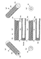
すなわち、前記回転体14に螺合する前部棒状部36は、図6に示すように、内外面にネジ部38(雄ネジのネジ部38a、雌ネジのネジ部38b)が形成されている。つまり、上記雌ネジからなるネジ部14bに螺合する外周面の雄ネジのネジ部38aが形成され、また、内面に棒部材34のネジ部34aに螺合する雌ネジ38bが形成されている。前部棒状部36の外周における雄ネジからなるネジ部38aは、前部棒状部36の前端部から後端部付近まで連続して形成されている。前部棒状部36の当該後端部は、ネジ山が形成されていない非形成部分38cになっている。
前記回転体14のネジ部14bにはネジを分断するスリットが形成されているものとすることができる(ネジ部14bにスリット14cが形成されものを後述の第3実施形態(図12参照)で説明する)。
前記回転体14のネジ部14bにはネジを分断するスリットが形成されているものとすることができる(ネジ部14bにスリット14cが形成されものを後述の第3実施形態(図12参照)で説明する)。
したがって、図2に示すように、回転体14(操作部16)のネジ部14bが前部棒状部36のネジ部38を介して、間接的に棒部材34のネジ部34aに螺合している。
また、前記ピストン18に固定された棒部材34のネジ部34aが前部棒状部36の内側ネジ部38bに螺合の滑り摩擦力は、前部棒状部36の外側のネジ部38aが回転体14のネジ部14bに螺合する滑り摩擦力よりも小さくなるように設定されている。
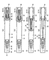
そして、図2(b)に示す状態から、前記操作部16の軸本体10と相対回転する操作をすることにより、前記滑り摩擦力の差から、前記ピストン18の棒部材34が前進しシール部32が前進する。ピストン18の前進後に、図2(c)に示す状態で、棒部材34が前部棒状部36にロックするので、さらに、操作部16を回転させると、前部棒状部36が回転体14に対して繰出しされて前進してシール部32をさらに前進させる機構によって、図2(b)から(d)に示すように、多段階に伸縮可能な構成としている。なお、回転体14は中空に形成されており、尾端を開放しているが、閉栓を嵌入して内部が見えないようにして、意匠性を向上させることもできる。
ここで、上記ピストン18は、シール部32と棒部材34とが連結された構造である。
棒部材34は、図3に示すように、前端・後端を除くほぼ中央部全体の外周面にネジ山の形成されたネジ部34aである。また、該棒部材34の前端にシール部32との係合部34bが異形に形成され、後端にネジ山が形成されていない非形成部分34cが形成されている。係合部34bは、軸方向に薄く、ほぼ盾形に形成されている
棒部材34は、図3に示すように、前端・後端を除くほぼ中央部全体の外周面にネジ山の形成されたネジ部34aである。また、該棒部材34の前端にシール部32との係合部34bが異形に形成され、後端にネジ山が形成されていない非形成部分34cが形成されている。係合部34bは、軸方向に薄く、ほぼ盾形に形成されている
シール部32は、図4に示すように、概略杯状または車輪状の回転体形状であってその外周面の前後端が中央よりも大径に形成されて、該外周面に2条周方向に沿って形成されたシール面が軸本体10の収容部12内壁に摺接する構成である。シール部32は、内部のハブ状部から後方に被係合部32aが筒状に後方向き突出して形成されている。
この被係合部32aは突出した筒状の部分が側面に切り込みが形成された閂構造等の係合構造であって、この切り込みから、前記棒部材34の係合部34b(図3に示す)を差し込んで装着することによって、シール部32と棒部材34とが回転方向及び前後方向に固定され、一体的なピストン18として前後動するものになる。
前記回転体14は、図5に示すように、概略中空筒状であって、外周が前部よりも後部が大径であって、使用者が摘まんで回転できる操作部16になっている。また、前部の外周面には軸本体10の回転自在に係合し抜け止めする嵌着部14aが環状のリブに形成されている。回転体14の内周面には、前部に雌ネジのネジ部14bが形成されている。
また、前記ピストン18後部の棒部材34が、シール部32と共に収容部12内壁に対して前後方向に移動可能で回転方向に規制されている。
このピストン18の回転方向の規制は、前記ピストン18において、その前部のシール部32の外周面が軸本体10の収容部12内壁に摺接し、軸線方向に移動可能であり、かつ、回転方向にはその摺接力によって容易に回転されないよう保持されている。すなわち、ピストン18は、その前部のシール部32が軸本体10の収容部12の内壁に摺接し、液状の内容物の漏出を防止するため適宜な締め代を持って摺接し、その締め代によって発生した摺接力によって円周方向に容易に回転されないよう保持されているものである。
ピストン18等各部は樹脂成型され、その寸法設定で締め代を調整する他、材質の選択で容易に回転できないものにできる。
ピストン18等各部は樹脂成型され、その寸法設定で締め代を調整する他、材質の選択で容易に回転できないものにできる。
第1実施形態に係る液状物繰出容器の繰出作動を説明する。
前記ピストン18に固定された棒部材34のネジ部34aが前部棒状部36の内側ネジ部38bに螺合し、前部棒状部36の外側のネジ部38aが回転体のネジ部14bに螺合している。
繰出容器は、未使用時には、図2(b)に示すように、ピストン18は後退限に位置して、収容部12が最大容積となっている。
使用時に、操作部16を摘んで回転体14を軸本体10に対して回転させる。使用者が、前記操作部16の軸本体10と相対回転する操作をすることにより、前記滑り摩擦力の差から、前記ピストン18の棒部材34が前進しシール部32が前進し、ピストン18が前進していく。ある程度前進すると、ネジ部34aのない非形成部分34cが前部棒状部36の内側ネジ部38bに当接し、前部棒状部36に対する固定状態とそれ以上に前進しないロック状態になる。前進限を図2(c)に示す。
さらに、操作部16を回転させると、外側の雄ネジのネジ部38aが回転体14の雌ネジ14bに螺合しているため、図2(d)に示すように、外側前部棒状部36が回転体14に対して繰出しされて前進し、シール部32をさらに前進させる。なお、ネジ部38の非形成部分38cが回転体14の雌ネジ14bに突き当たるとそれ以上前進しなくなり、ピストン18の押し過ぎが防止できる。
以上の繰り出し行程となるため、液状物繰出容器は、ピストン18の棒部材34、前部棒状部36が回転体14に対して多段階に伸縮可能な構成になっている。
本発明は前記第1実施形態に係る液状物繰出し容器の構成に限定されず、種々に変形実施できる。
本発明の第2実施形態に係る液状物繰出容器を、図7、図8、図9によって説明する。第1実施形態と同様部分に同一符号を付している。
この液状物繰出容器では、図7~図9に示すように、ピストン18が、その前部のシール部32と後部の棒部材34とが一体に樹脂成型されているものである。外周にネジ部を有する棒部材34が一体なので、ピストン18と同じく軸線方向に移動可能で回転方向には規制されて配置されているものになっている。また、第1実施形態と同じく非形成部分34cはネジが形成されてないことから前部棒状部36に組み付けるときにおいては雌ネジ38bにスリットが形成され分断するように入っているか、或いは非形成部分34cにスリットが入っている、或いはその両方にスリットが入っているものにすることもできる。
また、塗布体20は概略円錐形状であって、外周に突出する円盤部(フランジ状部)を同心円状に先端から後端にかけて所定間隔で複数設置したものである。この塗布体20はマスカラ等の液を塗布するのに用いて円盤部の突起によりまつげ等に絡みやすく充分な塗布ができる構造のものである。その塗布体20の周囲は、先軸で覆って軸本体10の先端部10aに嵌入している。
この第2実施形態に係る液状物繰出容器では、第1実施形態に比較して、ピストン18が簡単な一体構成であるので組立工数を減少させることができる。
本発明の第3実施形態に係る液状物繰出容器を、図10~図13によって説明する。第1実施形態と同様部分に同一符号を付している。
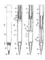
図10はキャップを設けた不使用状態を、図11はキャップを外した使用状態を、図12は回転体の説明図、図13は液状物繰出容器の後部の縦断説明図である。
図10はキャップを設けた不使用状態を、図11はキャップを外した使用状態を、図12は回転体の説明図、図13は液状物繰出容器の後部の縦断説明図である。
この液状物繰出容器では、ピストン18は、シール部32と棒部材34とが実施形態1と同様に連結された構造である。
また、図10に示すように、不使用時にキャップ22を嵌めた状態にし、図11に示すように、使用時にキャップ22を外した状態にする。ピストン18の繰り出し前は図10(a)、図11(a)に示す状態となり、ピストン18の繰り出し途中前は図10(b)、図11(b)に示す状態になり、ピストン18の前進限が図10(c)、図11(c)に示す状態になる。
また、図10に示すように、不使用時にキャップ22を嵌めた状態にし、図11に示すように、使用時にキャップ22を外した状態にする。ピストン18の繰り出し前は図10(a)、図11(a)に示す状態となり、ピストン18の繰り出し途中前は図10(b)、図11(b)に示す状態になり、ピストン18の前進限が図10(c)、図11(c)に示す状態になる。
ここで、回転体14は、図12、図13に示すように、概略中空筒状であって、外周が前部よりも後部が大径であって、使用者が摘まんで回転できる操作部16になっている。また、前部の外周面には軸本体10の回転自在に係合し抜け止めする嵌着部14aの環状にリブが形成されている。また、回転体14の内周面には、前部に雌ネジのネジ部14bが形成されている。
また、前記回転体14の前部棒状部の一端に、ネジ部を分断するスリットが設けられている。第3実施形態では、回転体14の一部の操作部16よりも前方の部分に、前部棒状部36の螺号する部分にネジ部14bを分断するスリット14cが形成されている。
すなわち、回転体14の前部には、径方向の2箇所の対の位置に、ネジ部14bの形成箇所を縦断するように、前端から後方に切り込んでスリット14cが形成されている。
このスリット14cの形成によって、前部棒部材36の組み付けにおいて回転体14の前部がスリット14cから若干拡径して前部棒状部36を緩やかにねじ込むことができる。また、スリット14cからの拡径によって前部棒部材36をそのまま圧入することも可能である。
すなわち、回転体14の前部には、径方向の2箇所の対の位置に、ネジ部14bの形成箇所を縦断するように、前端から後方に切り込んでスリット14cが形成されている。
このスリット14cの形成によって、前部棒部材36の組み付けにおいて回転体14の前部がスリット14cから若干拡径して前部棒状部36を緩やかにねじ込むことができる。また、スリット14cからの拡径によって前部棒部材36をそのまま圧入することも可能である。
繰り出し機構においては、図13に示すように、スリット14cが軸本体10の内周面(符号10bで示す)に近接して設けることができる。第3実施形態では、スリット14cと内周面10bとの間隔δを0.5mm以下としている。この間隔は適宜に選択実施できる。
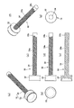
本発明の第4実施形態に係る液状物繰出容器を、図14によって説明する。第1実施形態と同様部分に同一符号を付している。
図14に示すように、この液状物繰出容器では、前部棒状部36の外周に螺合し、回転体14のネジ部14bの内周に螺合する後部筒部材40が設けられている。
前部棒状部36と回転体14との間に、弾発体(スプリング)42が設けられている。この液状物繰出容器は、弾発体42が前部棒状部36を前方に付勢する構造になっているので、図14(a)~(b)に示すように、回転体14の回転による前進力だけでなく、併せて弾発体42の押圧力で、前部棒状部36を介した前進力を加味してピストン18を前進させ得る。
前部棒状部36と回転体14との間に、弾発体(スプリング)42が設けられている。この液状物繰出容器は、弾発体42が前部棒状部36を前方に付勢する構造になっているので、図14(a)~(b)に示すように、回転体14の回転による前進力だけでなく、併せて弾発体42の押圧力で、前部棒状部36を介した前進力を加味してピストン18を前進させ得る。
具体的には、第4実施形態においては、概略筒状の回転体14内に、上記の弾発体42の後端を受け止めるため、前方が開き、かつ、後方が閉じた略コップ状のスプリング受け44が前記回転体14の後部開口内を閉じるように設けられる。
また、前記回転体14と前記前部棒状部36との間に同軸状に、後部筒部材40が配設されている。この後部筒部材40は、内周面と外周面にネジ(雌ネジと雄ネジ)が形成されている。後部筒部材40において、外周面には前後にわたって雄ネジが形成され、また、内周面には前部が細径で雌ネジが形成され、その雌ネジの後端から段部を介した後部では拡径してネジのないフラットの内面に形成される。
そして、前記回転体14の内周のネジ部14bは、前記後部筒部材40の外周面の雄ネジに螺合し、また、前記前部棒状部36の外側の雄ネジ38aは、前記後部筒部材40の内周面の雌ネジに螺合する。なお、ピストン18は、前部のシール部32が後部の棒状部34の前端に、前方から挿通されたビスのねじ込みによって結合されている構成となっている。
なお、ピストン18は、第1の実施形態である図1や第3の実施形態である図10に示すようなシール部32と棒状部34との結合されている構成としても良い。或いは第2の実施形態である図8に示すようなシール部32と棒状部34が一体となった構成としても良い。
なお、ピストン18は、第1の実施形態である図1や第3の実施形態である図10に示すようなシール部32と棒状部34との結合されている構成としても良い。或いは第2の実施形態である図8に示すようなシール部32と棒状部34が一体となった構成としても良い。
前記後部筒部材40の後部は、スプリング受け44に収容された弾発体(スプリング)42が受け止め可能に設けられ、後部筒部材40を前方に押圧している。
図14(a)~(b)に示すように、使用者が操作して回転体14を回転させ始めのときにその回転力による後部筒部材40の前進力だけでなく、併せて弾発体42の押圧力が後部筒部材40の前進力として作用する。
したがって、回転体14の回転力と弾発体42の弾発力と併せて後部筒部材40の前進力になり、前部棒状部36を介してピストン18に前進力を加えて、該ピストン18を前進させる。なお、後部筒部材40の後端外周のフランジ状部が、回転体14の内周の段部に当接して後部筒部材40の前進限になると、ロック状態になり、回転体14の回転で後部筒部材40は供回りをする。
したがって、回転体14の回転力と弾発体42の弾発力と併せて後部筒部材40の前進力になり、前部棒状部36を介してピストン18に前進力を加えて、該ピストン18を前進させる。なお、後部筒部材40の後端外周のフランジ状部が、回転体14の内周の段部に当接して後部筒部材40の前進限になると、ロック状態になり、回転体14の回転で後部筒部材40は供回りをする。
その後は、回転体14の繰り出し操作によって、同図(c)に示すように後部筒部材40が前部棒状部36を繰り出して前進させ、前進限になると、同図(d)に示すように、前部棒状部36が回転して棒部材34を介してピストン18を前進させる。
したがって、第4実施形態の液状物繰出容器においては、ピストン18の繰り出し操作において、回転体14の回転力と共に弾発体42による押圧により、ピストン18への繰り出しトルクを付与することができる。特にネジ外径の大きい回転体14によるピストン18の繰り出しをサポートすることができるため、軽い回転力で塗布液を塗出することができる。これは、後部筒部材40と弾発体42とを設けない状態で回転体14のネジ外径を大きくした場合、回転体14のネジ部14bの内径とそれに螺合する前部棒状部36のネジ外径が大きくなって、螺合するネジ同士の摺動抵抗が大きくなるため、繰出し操作には回転体14に大きな回転力(トルク)が必要になるからである。これに対して、第4実施形態では、弾発体42による付勢力でピストン18前進をアシストするので、回転体14を軽く回すことができる。
また、ネジのピッチを大きくすることで、ユーザーが使い始めの際により少ない数の回転繰り出し操作で内容物を素早く繰出すことが可能になると共に、ネジのピッチを大きくすることによる繰出し操作の回転力(トルク)は増大するが、弾発体42のアシストにより軽い力で液状物を素早く繰出すことが可能となる。
なお、本発明にて説明した、第1実施形態~第4実施形態では、棒部材34と前部棒状部36と回転体14で二段階のピストン18を前進繰出し駆動ができるようにしていたが、前部棒状部を複数にして3以上の多段階で繰出し駆動できるようにすることも可能である。
また棒部材、前部棒状部、回転体のネジ部の雄ネジ、雌ネジの設定を他のものにできる。例えば、棒部材を中空にしてその内部に前部棒状部を螺合しさらに回転体から棒状の雄ネジを前部棒状部内に螺合させる構造とすることができる。
本発明の液体の流動体(液状物)の化粧料や薬品の他、口腔清浄剤、薬剤等、液状物を軸本体の収容部内に収容し、尾端を回転させる繰出し操作によって収容した液状物を塗布体に送り出す液状物繰出容器に利用することができる。
10 軸本体
10a 先端部
12 収容部
14 回転体
14a 嵌着部
14b ネジ部
16 操作部
18 ピストン
18b 被係合部
20 塗布体
22 キャップ
30 先軸
32 シール部
32a 被係合部
34 棒部材
34a ネジ部
34b 係合部
34c 非形成部分
36 前部棒状部
38 ネジ部
38a 外側の雄ネジ
38b 内側の雌ネジ
40 後部筒部材
42 弾発体
10a 先端部
12 収容部
14 回転体
14a 嵌着部
14b ネジ部
16 操作部
18 ピストン
18b 被係合部
20 塗布体
22 キャップ
30 先軸
32 シール部
32a 被係合部
34 棒部材
34a ネジ部
34b 係合部
34c 非形成部分
36 前部棒状部
38 ネジ部
38a 外側の雄ネジ
38b 内側の雌ネジ
40 後部筒部材
42 弾発体
Claims (7)
- 軸本体に設けた収容部内に液状の内容物を収容し、軸本体後端部から露出した回転体の操作部を軸本体と相対回転することにより収容部内でピストンを前進させて、該内容物を軸本体先方に向けて繰出す液状物繰出容器において、
ピストンは、その前部のシール部が軸本体の収容部内壁に摺接し、その後部には内周或いは外周にネジ部を有する棒部材が軸線方向に移動可能で回転方向には規制されて配置され、
前記操作部から前方に延びた前部棒状部には、ピストン後部の棒部材のネジ部に直接または間接的に螺合するネジ部が形成されており、
前記操作部を軸本体と相対回転させる操作をすることにより、前記ピストンが前進し、前進後に前部棒状部が多段階に伸縮可能に構成されていることを特徴とする液状物繰出容器。 - 前記ピストン後部の棒部材が、シール部と共に収容部内壁に対して前後方向に移動可能で回転方向に規制され、
前記ピストンは、その前部のシール部の外周面が軸本体の収容部内壁に摺接し、軸線方向に移動可能であり、かつ、回転方向にはその摺接力によって容易に回転されないよう保持されていることを特徴とする請求項1記載の液状物繰出容器。 - 前記ピストンは、その前部のシール部が軸本体収容部の内壁に摺接し、液状の内容物の漏出を防止するため適宜な締め代を持って摺接し、その締め代によって発生した摺接力によって円周方向に容易に回転されないよう保持されていることを特徴とする請求項2記載の液状物繰出容器。
- 前記ピストン後部の棒部材は外周或いは内周にネジ部が形成され、前記回転体の前記操作部から前方に延びた前部棒状部には、前記ピストン後部の棒部材ネジ部に直接又は間接的に螺合するネジ部が形成されており、互いのネジ部が螺合する棒部材及び前部棒状部のいずれかの一端にネジ形状のないネジ不形成部を設けたことを特徴とする請求項1から3のうちの1項に記載の液状物繰出容器。
- 前記ピストン後部の棒部材は外周或いは内周にネジ部が形成され、前記回転体の前記操作部から前方に延びた前部棒状部には、前記ピストン後部の棒部材のネジ部に直接又は間接的に螺合するネジ部が形成されており、
前記回転体の前部棒状部の一端に、ネジ部を分断するスリットが設けられていることを特徴とする請求項1から4のうちの1項に記載の液状物繰出容器。 - 前記スリットは、軸本体の内周面に近接して設けられていることを特徴とする請求項5記載の液状物繰出容器。
- 前記回転体と前部棒状部との間に弾発体を設けたことを特徴とする請求項1から6のうちの1項に記載の液状物繰出容器。
Priority Applications (2)
| Application Number | Priority Date | Filing Date | Title |
|---|---|---|---|
| EP14753988.6A EP2959794B1 (en) | 2013-02-25 | 2014-02-25 | Liquid substance advancing container |
| US14/769,659 US9924777B2 (en) | 2013-02-25 | 2014-02-25 | Liquid substance advancing container |
Applications Claiming Priority (4)
| Application Number | Priority Date | Filing Date | Title |
|---|---|---|---|
| JP2013-034730 | 2013-02-25 | ||
| JP2013034730 | 2013-02-25 | ||
| JP2014029446A JP6424005B2 (ja) | 2013-02-25 | 2014-02-19 | 液状物繰出容器 |
| JP2014-029446 | 2014-02-19 |
Publications (1)
| Publication Number | Publication Date |
|---|---|
| WO2014129645A1 true WO2014129645A1 (ja) | 2014-08-28 |
Family
ID=51391421
Family Applications (1)
| Application Number | Title | Priority Date | Filing Date |
|---|---|---|---|
| PCT/JP2014/054430 Ceased WO2014129645A1 (ja) | 2013-02-25 | 2014-02-25 | 液状物繰出容器 |
Country Status (4)
| Country | Link |
|---|---|
| US (1) | US9924777B2 (ja) |
| EP (1) | EP2959794B1 (ja) |
| JP (1) | JP6424005B2 (ja) |
| WO (1) | WO2014129645A1 (ja) |
Cited By (1)
| Publication number | Priority date | Publication date | Assignee | Title |
|---|---|---|---|---|
| CN106793861A (zh) * | 2014-10-08 | 2017-05-31 | 衍宇株式会社 | 按钮型笔式化妆品容器 |
Families Citing this family (1)
| Publication number | Priority date | Publication date | Assignee | Title |
|---|---|---|---|---|
| CN205658538U (zh) * | 2016-05-31 | 2016-10-26 | 洽兴包装工业(中国)有限公司 | 大容量化妆笔 |
Citations (6)
| Publication number | Priority date | Publication date | Assignee | Title |
|---|---|---|---|---|
| JPS633311U (ja) * | 1986-06-23 | 1988-01-11 | ||
| JP2004160117A (ja) * | 2002-11-11 | 2004-06-10 | Masayuki Kuzuu | 口紅等が全て使い切る事ができる口紅等の収納容器 |
| JP2007130438A (ja) * | 2005-10-12 | 2007-05-31 | Tokiwa Corp | 充填物押出容器 |
| JP2007143857A (ja) | 2005-11-28 | 2007-06-14 | Tokiwa Corp | 内容物押出容器 |
| JP2008043590A (ja) * | 2006-08-18 | 2008-02-28 | Tokiwa Corp | 充填物押出容器 |
| JP2010227553A (ja) | 2009-03-03 | 2010-10-14 | Mitsubishi Pencil Co Ltd | 液状物繰出容器 |
Family Cites Families (13)
| Publication number | Priority date | Publication date | Assignee | Title |
|---|---|---|---|---|
| JPS633311A (ja) | 1986-06-23 | 1988-01-08 | Toshiba Corp | 三次元位置検出装置 |
| US5100252A (en) * | 1990-07-02 | 1992-03-31 | Grigory Podolsky | Toothbrush |
| JP2736039B2 (ja) * | 1994-08-25 | 1998-04-02 | 株式会社トキワ | 化粧料繰り出し容器 |
| FR2825904B1 (fr) | 2001-06-15 | 2004-07-09 | Oreal | Stick, notamment pour un produit sous forme d'une creme, d'un gel, ou d'une pate |
| WO2005046423A1 (en) * | 2003-11-13 | 2005-05-26 | Unilever Plc | Fabric cleaning fluid and dispensing device |
| JP4739847B2 (ja) | 2005-07-28 | 2011-08-03 | 株式会社トキワ | 充填物押出容器 |
| EP1769698A1 (de) * | 2005-09-30 | 2007-04-04 | OEKAMETALL OEHLHORN GmbH & Co. KG | Behälter zum Auftragen von Kosmetika, insbesondere Lippenpomade, vorzugsweise in Stiftform |
| US8172472B2 (en) * | 2007-11-08 | 2012-05-08 | Tokiwa Corporation | Stick-shaped material extruding container |
| US8104984B2 (en) | 2007-12-14 | 2012-01-31 | Tokiwa Corporation | Filled material extruding container |
| JP2009247427A (ja) * | 2008-04-02 | 2009-10-29 | Mitsubishi Pencil Co Ltd | 回転式繰出容器 |
| JP5545681B2 (ja) * | 2009-03-03 | 2014-07-09 | 三菱鉛筆株式会社 | 液状物繰出容器 |
| JP5467952B2 (ja) * | 2010-07-07 | 2014-04-09 | 三菱鉛筆株式会社 | 塗布具 |
| KR101259431B1 (ko) | 2011-07-26 | 2013-04-30 | (주)연우 | 펜슬형 화장품 용기 |
-
2014
- 2014-02-19 JP JP2014029446A patent/JP6424005B2/ja not_active Expired - Fee Related
- 2014-02-25 WO PCT/JP2014/054430 patent/WO2014129645A1/ja not_active Ceased
- 2014-02-25 US US14/769,659 patent/US9924777B2/en not_active Expired - Fee Related
- 2014-02-25 EP EP14753988.6A patent/EP2959794B1/en not_active Not-in-force
Patent Citations (6)
| Publication number | Priority date | Publication date | Assignee | Title |
|---|---|---|---|---|
| JPS633311U (ja) * | 1986-06-23 | 1988-01-11 | ||
| JP2004160117A (ja) * | 2002-11-11 | 2004-06-10 | Masayuki Kuzuu | 口紅等が全て使い切る事ができる口紅等の収納容器 |
| JP2007130438A (ja) * | 2005-10-12 | 2007-05-31 | Tokiwa Corp | 充填物押出容器 |
| JP2007143857A (ja) | 2005-11-28 | 2007-06-14 | Tokiwa Corp | 内容物押出容器 |
| JP2008043590A (ja) * | 2006-08-18 | 2008-02-28 | Tokiwa Corp | 充填物押出容器 |
| JP2010227553A (ja) | 2009-03-03 | 2010-10-14 | Mitsubishi Pencil Co Ltd | 液状物繰出容器 |
Non-Patent Citations (1)
| Title |
|---|
| See also references of EP2959794A4 * |
Cited By (2)
| Publication number | Priority date | Publication date | Assignee | Title |
|---|---|---|---|---|
| CN106793861A (zh) * | 2014-10-08 | 2017-05-31 | 衍宇株式会社 | 按钮型笔式化妆品容器 |
| EP3228211A4 (en) * | 2014-10-08 | 2018-07-11 | Yonwoo Co.,Ltd | Button-type pencil cosmetic dispenser |
Also Published As
| Publication number | Publication date |
|---|---|
| EP2959794A1 (en) | 2015-12-30 |
| US9924777B2 (en) | 2018-03-27 |
| US20160007715A1 (en) | 2016-01-14 |
| EP2959794A4 (en) | 2016-10-12 |
| JP6424005B2 (ja) | 2018-11-14 |
| EP2959794B1 (en) | 2020-12-09 |
| JP2014184135A (ja) | 2014-10-02 |
Similar Documents
| Publication | Publication Date | Title |
|---|---|---|
| JP5545632B2 (ja) | 液状物繰出容器 | |
| JP5108919B2 (ja) | 充填物押出容器 | |
| JP6818311B2 (ja) | 塗布容器及び塗布容器の製造方法 | |
| KR101579643B1 (ko) | 노크식 도포구 | |
| JP6600489B2 (ja) | 回転繰出容器 | |
| JP6045127B2 (ja) | 塗布具 | |
| US6957753B2 (en) | Movable body feeding apparatus | |
| JP6424005B2 (ja) | 液状物繰出容器 | |
| JP7394199B2 (ja) | 化粧料塗布具 | |
| JP6700676B2 (ja) | 回転繰出容器 | |
| JP2022190935A (ja) | 棒状物繰出容器 | |
| CN106660064A (zh) | 用于多筒管的转动式配制器 | |
| JP4939334B2 (ja) | 塗布材押出容器 | |
| KR20180046931A (ko) | 펜타입 화장품 용기 | |
| JP5610775B2 (ja) | 液体塗布具 | |
| JP2007330814A5 (ja) | ||
| JP6001416B2 (ja) | 繰出し容器 | |
| JP5545681B2 (ja) | 液状物繰出容器 | |
| EP1698251B1 (en) | Stick-form cosmetic material feeding container | |
| JP2023013700A (ja) | カートリッジ式化粧料押出容器 | |
| JP5234596B2 (ja) | ノック式繰出容器 | |
| JP2017113163A (ja) | 塗布具 | |
| JP6262466B2 (ja) | 固形棒状化粧料容器 | |
| JP7145478B2 (ja) | 棒状化粧料繰出容器 | |
| JP7286661B2 (ja) | 繰出し筒、繰出し容器、及び繰出し筒と被繰出部材とケースの組み付け方法 |
Legal Events
| Date | Code | Title | Description |
|---|---|---|---|
| 121 | Ep: the epo has been informed by wipo that ep was designated in this application |
Ref document number: 14753988 Country of ref document: EP Kind code of ref document: A1 |
|
| WWE | Wipo information: entry into national phase |
Ref document number: 14769659 Country of ref document: US |
|
| NENP | Non-entry into the national phase |
Ref country code: DE |
|
| WWE | Wipo information: entry into national phase |
Ref document number: 2014753988 Country of ref document: EP |