WO2014129703A1 - Capteur de proximité par induction - Google Patents
Capteur de proximité par induction Download PDFInfo
- Publication number
- WO2014129703A1 WO2014129703A1 PCT/KR2013/004705 KR2013004705W WO2014129703A1 WO 2014129703 A1 WO2014129703 A1 WO 2014129703A1 KR 2013004705 W KR2013004705 W KR 2013004705W WO 2014129703 A1 WO2014129703 A1 WO 2014129703A1
- Authority
- WO
- WIPO (PCT)
- Prior art keywords
- winding unit
- sensor
- sensor coil
- proximity sensor
- inductive proximity
- Prior art date
- Legal status (The legal status is an assumption and is not a legal conclusion. Google has not performed a legal analysis and makes no representation as to the accuracy of the status listed.)
- Ceased
Links
Images

Classifications
-
- G—PHYSICS
- G01—MEASURING; TESTING
- G01D—MEASURING NOT SPECIALLY ADAPTED FOR A SPECIFIC VARIABLE; ARRANGEMENTS FOR MEASURING TWO OR MORE VARIABLES NOT COVERED IN A SINGLE OTHER SUBCLASS; TARIFF METERING APPARATUS; MEASURING OR TESTING NOT OTHERWISE PROVIDED FOR
- G01D5/00—Mechanical means for transferring the output of a sensing member; Means for converting the output of a sensing member to another variable where the form or nature of the sensing member does not constrain the means for converting; Transducers not specially adapted for a specific variable
- G01D5/12—Mechanical means for transferring the output of a sensing member; Means for converting the output of a sensing member to another variable where the form or nature of the sensing member does not constrain the means for converting; Transducers not specially adapted for a specific variable using electric or magnetic means
- G01D5/14—Mechanical means for transferring the output of a sensing member; Means for converting the output of a sensing member to another variable where the form or nature of the sensing member does not constrain the means for converting; Transducers not specially adapted for a specific variable using electric or magnetic means influencing the magnitude of a current or voltage
- G01D5/20—Mechanical means for transferring the output of a sensing member; Means for converting the output of a sensing member to another variable where the form or nature of the sensing member does not constrain the means for converting; Transducers not specially adapted for a specific variable using electric or magnetic means influencing the magnitude of a current or voltage by varying inductance, e.g. by a movable armature
- G01D5/2006—Mechanical means for transferring the output of a sensing member; Means for converting the output of a sensing member to another variable where the form or nature of the sensing member does not constrain the means for converting; Transducers not specially adapted for a specific variable using electric or magnetic means influencing the magnitude of a current or voltage by varying inductance, e.g. by a movable armature by influencing the self-induction of one or more coils
-
- G—PHYSICS
- G01—MEASURING; TESTING
- G01B—MEASURING LENGTH, THICKNESS OR SIMILAR LINEAR DIMENSIONS; MEASURING ANGLES; MEASURING AREAS; MEASURING IRREGULARITIES OF SURFACES OR CONTOURS
- G01B7/00—Measuring arrangements characterised by the use of electric or magnetic techniques
- G01B7/14—Measuring arrangements characterised by the use of electric or magnetic techniques for measuring distance or clearance between spaced objects or spaced apertures
-
- H—ELECTRICITY
- H03—ELECTRONIC CIRCUITRY
- H03K—PULSE TECHNIQUE
- H03K17/00—Electronic switching or gating, i.e. not by contact-making and –breaking
- H03K17/14—Modifications for compensating variations of physical values, e.g. of temperature
-
- H—ELECTRICITY
- H03—ELECTRONIC CIRCUITRY
- H03K—PULSE TECHNIQUE
- H03K17/00—Electronic switching or gating, i.e. not by contact-making and –breaking
- H03K17/94—Electronic switching or gating, i.e. not by contact-making and –breaking characterised by the way in which the control signals are generated
- H03K17/945—Proximity switches
- H03K17/95—Proximity switches using a magnetic detector
- H03K17/9502—Measures for increasing reliability
-
- H—ELECTRICITY
- H03—ELECTRONIC CIRCUITRY
- H03K—PULSE TECHNIQUE
- H03K17/00—Electronic switching or gating, i.e. not by contact-making and –breaking
- H03K17/94—Electronic switching or gating, i.e. not by contact-making and –breaking characterised by the way in which the control signals are generated
- H03K17/945—Proximity switches
- H03K17/95—Proximity switches using a magnetic detector
- H03K17/9505—Constructional details
-
- H—ELECTRICITY
- H03—ELECTRONIC CIRCUITRY
- H03K—PULSE TECHNIQUE
- H03K17/00—Electronic switching or gating, i.e. not by contact-making and –breaking
- H03K17/94—Electronic switching or gating, i.e. not by contact-making and –breaking characterised by the way in which the control signals are generated
- H03K17/945—Proximity switches
- H03K17/95—Proximity switches using a magnetic detector
- H03K17/952—Proximity switches using a magnetic detector using inductive coils
- H03K2017/9527—Details of coils in the emitter or receiver; Magnetic detector comprising emitting and receiving coils
Definitions
- the present invention relates to an inductive proximity sensor and, more particularly, to an inductive proximity sensor capable of precisely detecting whether a metal object approaches or not irrespective of temperature or surrounding environments.
- a proximity sensor is used to detect whether an object to be detected approaches or not within a detection range.
- a proximity sensor is used in the automation of manufacturing equipment in order to detect whether a metal object approaches or not.
- the switch of a brake light for a vehicle is installed in such a way as to operate in conjunction with a brake pedal and is also used when whether or not a driver has pressed the brake pedal with his or her foot is detected using a proximity sensor in a non-contactless way.
- Korean Patent Registration No. 10-0689196 discloses a technique related to a switch for a vehicle using the principle of a proximity sensor.
- a coil has an inductance value varying according to a change of temperature, etc. Accordingly, whether an object to be detected approaches or not can be detected more precisely by compensating for the varying inductance value.
- the present invention has been made in view of the above problems, and it is an object of the present invention to provide an inductive proximity sensor capable of detecting whether an object to be detected approaches or not always precisely because a change of an external environment, such as temperature, is autonomously compensated for.
- An inductive proximity sensor in accordance with an embodiment of the present invention includes a bobbin configured to have a first winding unit formed on the side to which an object to be detected approaches and a second winding unit formed with a blocking plate for blocking a magnetic field interposed between the first winding unit and the second winding unit; a pair of first and second sensor coils wound on the first and the second winding units of the bobbin, respectively, and configured to have respective one ends grounded together; and a signal processor coupled with the other ends of the first and the second sensor coils and a line connected to a ground portion where the one ends are grounded together and configured to analyze a change of a received first signal based on a received second signal by processing a change of received signals to determine whether the object to be detected approaches or not based on a result of the determination.
- the thickness of the blocking plate preferably is 3 mm or more in order to minimize a change of a magnetic field occurring when the object to be detected approaches.
- the length of the winding of the first sensor coil is the same as the length of the winding of the second sensor coil.
- a signal value of the first sensor coil having a varying magnetic field is analyzed based on whether an object to be detected approaches or not on the basis of a signal value of the second sensor coil having a fixed magnetic field although the object to be detected approaches, and whether the object to be detected approaches or not is detected based on a result of the analysis. Accordingly, an influence due to surrounding environments, such as temperature, can be minimized, and detection can be performed always precisely.
- a change in the signal values of the first sensor coil and the second sensor coil attributable to surrounding environments, such as temperature, is the same in the first sensor coil and the second sensor coil. If a signal value of the first sensor coil is analyzed based on a signal value of the second sensor coil that is not influenced by whether the object to be detected approaches or not, whether the object to be detected approaches or not can be detected always precisely.
- FIG. 1 is a side view showing an inductive proximity sensor in accordance with an embodiment of the present invention
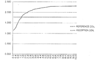
- FIG. 2 is a graph showing a change in the inductance values measured when an object to be detected approaches in the inductive proximity sensor in which a blocking plate has a thickness of 3 mm or more in accordance with an embodiment of the present invention.
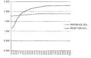
- FIG. 3 is a graph showing a change in the inductance values measured when an object to be detected approaches in the inductive proximity sensor in which a blocking plate has a thickness of less than 3 mm in accordance with an embodiment of the present invention.
- the present invention can be implemented in various forms and is not limited to the following embodiment.
- the inductive proximity sensor in accordance with an embodiment of the present invention includes a bobbin 10, a pair of a first sensor coil 20 and a second sensor coil 30, and a signal processor 50, as shown in FIG. 1.
- a first winding unit 12 on which the first sensor coil 20 is wound and a second winding unit 14 on which the second sensor coil 30 is wound are formed in the bobbin 10.
- the first winding unit 12 can be formed on the side to which an object to be detected approaches, and a blocking plate 16 for blocking a magnetic field is formed between the first winding unit 12 and the second winding unit 14.
- the bobbin 10 is made of synthetic resin.
- the first sensor coil 20 is wound on the first winding unit 12 of the bobbin 10
- the second sensor coil 30 is wound on the second winding unit 14 of the bobbin 10.
- the length of the winding of the first sensor coil 20 is the same as the length of the winding of the second sensor coil 30.
- the blocking plate 16 formed between the first winding unit 12 and the second winding unit 14 maintains a thickness S of 3 mm or more.
- an inductance value of the second sensor coil 30 is changed when an object to be detected, for example, a metal material approaches the first winding unit 12.
- the thickness S of the blocking plate 16 is increased, a change in the magnetic field of the second sensor coil 30 due to an object to be detected can be minimized, but the thickness S of the blocking plate 16 preferably is determined by taking the total size and weight of the bobbin 10 and a reduction raw material costs into consideration.
- a first ground terminal 24, that is, one end of the first sensor coil 20, and a second ground terminal 34, that is, one end of the second sensor coil 30, are grounded together.
- a ground signal line 40 is drawn from a ground portion where the first ground terminal 24 of the first sensor coil 20 and the second ground terminal 34 of the second sensor coil 30 are grounded together.
- a first sensor signal line 22 is drawn from the other end of the first sensor coil 20, and a second sensor signal line 32 is drawn from the other end of the second sensor coil 30.
- the ground signal line 40, the first sensor signal line 22, and the second sensor signal line 32 are coupled with the signal processor 50.
- the signal processor 50 compares a signal value (i.e., inductance value) received through the first sensor signal line 22 and the ground signal line 40 with a signal value (i.e., inductance value) received through the second sensor signal line 32 and the ground signal line 40 and determines whether an object to be detected approaches or not based on a result of the comparison.
- a signal value i.e., inductance value
- the signal processor 50 can determine a change of a signal value (i.e., inductance value), received through the first sensor signal line 22 and the ground signal line 40, on the basis of a signal value (i.e., inductance value) received through the second sensor signal line 32 and the ground signal line 40 and detects whether an object to be detected approaches or not based on a result of the determination.
- a signal value i.e., inductance value
- FIG. 2 is a graph showing a change in the inductance values measured when an object to be detected approaches in the inductive proximity sensor in which the blocking plate 16 has a thickness of 3 mm or more in accordance with an embodiment of the present invention
- FIG. 3 is a graph showing a change in the inductance values measured when an object to be detected approaches in the inductive proximity sensor in which the blocking plate 16 has a thickness of less than 3 mm in accordance with an embodiment of the present invention.
- a signal of a reference coil i.e., a blue line in FIG. 2
- a signal value i.e., inductance value
- a signal of a reference coil i.e., a blue line in FIG. 3
- a signal value i.e., inductance value
Landscapes
- Physics & Mathematics (AREA)
- General Physics & Mathematics (AREA)
- Switches That Are Operated By Magnetic Or Electric Fields (AREA)
Abstract
L'invention concerne un capteur de proximité par induction comprenant une bobine configurée pour avoir une première unité d'enroulement formée du côté vers lequel un objet devant être détecté approche et une seconde unité d'enroulement formée avec une plaque de blocage destinée à bloquer un champ magnétique se trouvant entre la première unité d'enroulement et la seconde unité d'enroulement ; une paire de premier et second bobinages de capteur enroulés sur les première et seconde unités d'enroulement de la bobine, respectivement, et configurés pour avoir chacun respectivement une extrémité mises à la masse ensemble ; et un processeur de signaux couplé avec les autres extrémités des premier et second bobinages de capteur et une ligne connectée à une partie masse où ladite extrémité respective de chaque bobinage sont mises à la masse ensemble et configurée pour analyser un changement d'un premier signal reçu en fonction d'un second signal reçu par le traitement d'un changement de signaux reçus pour déterminer si l'objet devant être détecté s'approche ou non en fonction d'un résultat de la détermination.
Applications Claiming Priority (2)
| Application Number | Priority Date | Filing Date | Title |
|---|---|---|---|
| KR10-2013-0018417 | 2013-02-21 | ||
| KR1020130018417A KR101421110B1 (ko) | 2013-02-21 | 2013-02-21 | 인덕턴스방식 근접센서 |
Publications (1)
| Publication Number | Publication Date |
|---|---|
| WO2014129703A1 true WO2014129703A1 (fr) | 2014-08-28 |
Family
ID=51391467
Family Applications (1)
| Application Number | Title | Priority Date | Filing Date |
|---|---|---|---|
| PCT/KR2013/004705 Ceased WO2014129703A1 (fr) | 2013-02-21 | 2013-05-29 | Capteur de proximité par induction |
Country Status (2)
| Country | Link |
|---|---|
| KR (1) | KR101421110B1 (fr) |
| WO (1) | WO2014129703A1 (fr) |
Families Citing this family (3)
| Publication number | Priority date | Publication date | Assignee | Title |
|---|---|---|---|---|
| KR101697975B1 (ko) * | 2015-03-10 | 2017-01-19 | 주식회사 트루윈 | 주파수 변조를 이용한 인덕턴스 방식의 변위센서 |
| KR102348877B1 (ko) * | 2017-08-09 | 2022-01-06 | 엘에스오토모티브테크놀로지스 주식회사 | 비접촉 브레이크 스위치 |
| KR102193218B1 (ko) | 2019-04-26 | 2020-12-18 | (주)인피니어 | 내구성이 우수한 근접 센서 모듈 |
Citations (5)
| Publication number | Priority date | Publication date | Assignee | Title |
|---|---|---|---|---|
| US5065093A (en) * | 1987-08-24 | 1991-11-12 | Catena Product Development B.V. | Inductive proximity sensor for detecting an object starting electrical conductivity |
| JPH05113302A (ja) * | 1990-05-03 | 1993-05-07 | Alessandro Dreoni | 誘導式近接センサおよび直線または回転式測定トランスジユーサ |
| US7129701B2 (en) * | 2004-11-18 | 2006-10-31 | Simmonds Precision Products, Inc. | Method of inductive proximity sensing |
| JP2009264992A (ja) * | 2008-04-28 | 2009-11-12 | Shinshu Univ | 誘導型近接センサ |
| US20120081106A1 (en) * | 2010-09-30 | 2012-04-05 | Rockwell Automation Technologies, Inc. | Double-coil inductive proximity sensor apparatus |
Family Cites Families (3)
| Publication number | Priority date | Publication date | Assignee | Title |
|---|---|---|---|---|
| JP5384838B2 (ja) | 2008-02-14 | 2014-01-08 | マミヤ・オーピー・ネクオス株式会社 | 近接センサおよびこの近接センサを遊技媒体の流路に配設した遊技機 |
| JP5150521B2 (ja) | 2009-01-16 | 2013-02-20 | アズビル株式会社 | 高周波発振形近接センサ |
| JP4852667B1 (ja) | 2011-03-04 | 2012-01-11 | 株式会社マコメ研究所 | 近接センサ |
-
2013
- 2013-02-21 KR KR1020130018417A patent/KR101421110B1/ko active Active
- 2013-05-29 WO PCT/KR2013/004705 patent/WO2014129703A1/fr not_active Ceased
Patent Citations (5)
| Publication number | Priority date | Publication date | Assignee | Title |
|---|---|---|---|---|
| US5065093A (en) * | 1987-08-24 | 1991-11-12 | Catena Product Development B.V. | Inductive proximity sensor for detecting an object starting electrical conductivity |
| JPH05113302A (ja) * | 1990-05-03 | 1993-05-07 | Alessandro Dreoni | 誘導式近接センサおよび直線または回転式測定トランスジユーサ |
| US7129701B2 (en) * | 2004-11-18 | 2006-10-31 | Simmonds Precision Products, Inc. | Method of inductive proximity sensing |
| JP2009264992A (ja) * | 2008-04-28 | 2009-11-12 | Shinshu Univ | 誘導型近接センサ |
| US20120081106A1 (en) * | 2010-09-30 | 2012-04-05 | Rockwell Automation Technologies, Inc. | Double-coil inductive proximity sensor apparatus |
Also Published As
| Publication number | Publication date |
|---|---|
| KR101421110B1 (ko) | 2014-07-18 |
Similar Documents
| Publication | Publication Date | Title |
|---|---|---|
| US7710109B2 (en) | Method and apparatus for position detection | |
| US10330707B2 (en) | Current sensor having conductor between pair of plate-like magnetic shields | |
| JP5723089B2 (ja) | 電磁界センサ及び受信器 | |
| US7714567B2 (en) | Power cable magnetic field sensor | |
| WO2014129703A1 (fr) | Capteur de proximité par induction | |
| WO2012022971A3 (fr) | Appareil permettant de détecter des objets ferromagnétiques et ensemble porte protégé | |
| JP4835960B2 (ja) | 移動体システム | |
| CN107036632B (zh) | 位置检测装置 | |
| CN103344818A (zh) | 非接触式验电器和验电方法 | |
| WO2006066566A3 (fr) | Systeme de detection et procede pour mesurer de maniere capacitive des signaux electromagnetiques d'origine biologique | |
| JP2017228185A5 (fr) | ||
| KR20200083920A (ko) | 용량성 센서를 사용하는 무선 전력 송신 | |
| JP7685081B2 (ja) | スチールコードプライ欠陥検出装置 | |
| JP2014071460A5 (ja) | 電磁誘導方式の位置検出センサ及び位置検出装置 | |
| EP3249363A1 (fr) | Procédé de blindage de transducteur à induction | |
| EP3032222B1 (fr) | Système de capteur de position linéaire sans contact | |
| WO2009111518A1 (fr) | Détecteur quotientométrique pour câbles électriques à courant alternatif | |
| US9958295B2 (en) | Device for compensating external magnetic stray fields or for compensating the influence of a magnetic field gradient on a magnetic field sensor | |
| US9453933B2 (en) | Method for determining the position of a mobile unit and installation for executing a method | |
| US20040008022A1 (en) | Current sensor | |
| WO2018012407A1 (fr) | Système de détection de marqueur magnétique et procédé de détection de marqueur magnétique | |
| KR20150111953A (ko) | 감지 디바이스를 제조하기 위한 방법 | |
| US9726520B2 (en) | Sensor for detecting a position of a transducer magnet | |
| WO2014191351A3 (fr) | Capteur inductif | |
| KR20160061358A (ko) | 변압기를 테스트하기 위한 방법 |
Legal Events
| Date | Code | Title | Description |
|---|---|---|---|
| 121 | Ep: the epo has been informed by wipo that ep was designated in this application |
Ref document number: 13875629 Country of ref document: EP Kind code of ref document: A1 |
|
| NENP | Non-entry into the national phase |
Ref country code: DE |
|
| 122 | Ep: pct application non-entry in european phase |
Ref document number: 13875629 Country of ref document: EP Kind code of ref document: A1 |