WO2014132443A1 - Dispositif d'épuration de gaz d'échappement pour moteur à combustion interne à allumage par étincelles - Google Patents
Dispositif d'épuration de gaz d'échappement pour moteur à combustion interne à allumage par étincelles Download PDFInfo
- Publication number
- WO2014132443A1 WO2014132443A1 PCT/JP2013/055688 JP2013055688W WO2014132443A1 WO 2014132443 A1 WO2014132443 A1 WO 2014132443A1 JP 2013055688 W JP2013055688 W JP 2013055688W WO 2014132443 A1 WO2014132443 A1 WO 2014132443A1
- Authority
- WO
- WIPO (PCT)
- Prior art keywords
- particulate filter
- temperature
- internal combustion
- combustion engine
- execution
- Prior art date
- Legal status (The legal status is an assumption and is not a legal conclusion. Google has not performed a legal analysis and makes no representation as to the accuracy of the status listed.)
- Ceased
Links
Images

Classifications
-
- F—MECHANICAL ENGINEERING; LIGHTING; HEATING; WEAPONS; BLASTING
- F02—COMBUSTION ENGINES; HOT-GAS OR COMBUSTION-PRODUCT ENGINE PLANTS
- F02D—CONTROLLING COMBUSTION ENGINES
- F02D41/00—Electrical control of supply of combustible mixture or its constituents
- F02D41/02—Circuit arrangements for generating control signals
- F02D41/04—Introducing corrections for particular operating conditions
- F02D41/12—Introducing corrections for particular operating conditions for deceleration
- F02D41/123—Introducing corrections for particular operating conditions for deceleration the fuel injection being cut-off
-
- F—MECHANICAL ENGINEERING; LIGHTING; HEATING; WEAPONS; BLASTING
- F02—COMBUSTION ENGINES; HOT-GAS OR COMBUSTION-PRODUCT ENGINE PLANTS
- F02D—CONTROLLING COMBUSTION ENGINES
- F02D41/00—Electrical control of supply of combustible mixture or its constituents
- F02D41/02—Circuit arrangements for generating control signals
- F02D41/021—Introducing corrections for particular conditions exterior to the engine
- F02D41/0235—Introducing corrections for particular conditions exterior to the engine in relation with the state of the exhaust gas treating apparatus
- F02D41/024—Introducing corrections for particular conditions exterior to the engine in relation with the state of the exhaust gas treating apparatus to increase temperature of the exhaust gas treating apparatus
- F02D41/025—Introducing corrections for particular conditions exterior to the engine in relation with the state of the exhaust gas treating apparatus to increase temperature of the exhaust gas treating apparatus by changing the composition of the exhaust gas, e.g. for exothermic reaction on exhaust gas treating apparatus
-
- F—MECHANICAL ENGINEERING; LIGHTING; HEATING; WEAPONS; BLASTING
- F02—COMBUSTION ENGINES; HOT-GAS OR COMBUSTION-PRODUCT ENGINE PLANTS
- F02D—CONTROLLING COMBUSTION ENGINES
- F02D41/00—Electrical control of supply of combustible mixture or its constituents
- F02D41/02—Circuit arrangements for generating control signals
- F02D41/021—Introducing corrections for particular conditions exterior to the engine
- F02D41/0235—Introducing corrections for particular conditions exterior to the engine in relation with the state of the exhaust gas treating apparatus
- F02D41/027—Introducing corrections for particular conditions exterior to the engine in relation with the state of the exhaust gas treating apparatus to purge or regenerate the exhaust gas treating apparatus
- F02D41/029—Introducing corrections for particular conditions exterior to the engine in relation with the state of the exhaust gas treating apparatus to purge or regenerate the exhaust gas treating apparatus the exhaust gas treating apparatus being a particulate filter
-
- F—MECHANICAL ENGINEERING; LIGHTING; HEATING; WEAPONS; BLASTING
- F02—COMBUSTION ENGINES; HOT-GAS OR COMBUSTION-PRODUCT ENGINE PLANTS
- F02P—IGNITION, OTHER THAN COMPRESSION IGNITION, FOR INTERNAL-COMBUSTION ENGINES; TESTING OF IGNITION TIMING IN COMPRESSION-IGNITION ENGINES
- F02P5/00—Advancing or retarding ignition; Control therefor
- F02P5/04—Advancing or retarding ignition; Control therefor automatically, as a function of the working conditions of the engine or vehicle or of the atmospheric conditions
- F02P5/145—Advancing or retarding ignition; Control therefor automatically, as a function of the working conditions of the engine or vehicle or of the atmospheric conditions using electrical means
- F02P5/15—Digital data processing
- F02P5/1502—Digital data processing using one central computing unit
- F02P5/1504—Digital data processing using one central computing unit with particular means during a transient phase, e.g. acceleration, deceleration, gear change
-
- F—MECHANICAL ENGINEERING; LIGHTING; HEATING; WEAPONS; BLASTING
- F02—COMBUSTION ENGINES; HOT-GAS OR COMBUSTION-PRODUCT ENGINE PLANTS
- F02D—CONTROLLING COMBUSTION ENGINES
- F02D41/00—Electrical control of supply of combustible mixture or its constituents
- F02D41/02—Circuit arrangements for generating control signals
- F02D41/021—Introducing corrections for particular conditions exterior to the engine
- F02D41/0235—Introducing corrections for particular conditions exterior to the engine in relation with the state of the exhaust gas treating apparatus
- F02D2041/0265—Introducing corrections for particular conditions exterior to the engine in relation with the state of the exhaust gas treating apparatus to decrease temperature of the exhaust gas treating apparatus
-
- F—MECHANICAL ENGINEERING; LIGHTING; HEATING; WEAPONS; BLASTING
- F02—COMBUSTION ENGINES; HOT-GAS OR COMBUSTION-PRODUCT ENGINE PLANTS
- F02D—CONTROLLING COMBUSTION ENGINES
- F02D2200/00—Input parameters for engine control
- F02D2200/02—Input parameters for engine control the parameters being related to the engine
- F02D2200/08—Exhaust gas treatment apparatus parameters
- F02D2200/0802—Temperature of the exhaust gas treatment apparatus
-
- F—MECHANICAL ENGINEERING; LIGHTING; HEATING; WEAPONS; BLASTING
- F02—COMBUSTION ENGINES; HOT-GAS OR COMBUSTION-PRODUCT ENGINE PLANTS
- F02D—CONTROLLING COMBUSTION ENGINES
- F02D2200/00—Input parameters for engine control
- F02D2200/02—Input parameters for engine control the parameters being related to the engine
- F02D2200/08—Exhaust gas treatment apparatus parameters
- F02D2200/0802—Temperature of the exhaust gas treatment apparatus
- F02D2200/0804—Estimation of the temperature of the exhaust gas treatment apparatus
-
- Y—GENERAL TAGGING OF NEW TECHNOLOGICAL DEVELOPMENTS; GENERAL TAGGING OF CROSS-SECTIONAL TECHNOLOGIES SPANNING OVER SEVERAL SECTIONS OF THE IPC; TECHNICAL SUBJECTS COVERED BY FORMER USPC CROSS-REFERENCE ART COLLECTIONS [XRACs] AND DIGESTS
- Y02—TECHNOLOGIES OR APPLICATIONS FOR MITIGATION OR ADAPTATION AGAINST CLIMATE CHANGE
- Y02T—CLIMATE CHANGE MITIGATION TECHNOLOGIES RELATED TO TRANSPORTATION
- Y02T10/00—Road transport of goods or passengers
- Y02T10/10—Internal combustion engine [ICE] based vehicles
- Y02T10/12—Improving ICE efficiencies
-
- Y—GENERAL TAGGING OF NEW TECHNOLOGICAL DEVELOPMENTS; GENERAL TAGGING OF CROSS-SECTIONAL TECHNOLOGIES SPANNING OVER SEVERAL SECTIONS OF THE IPC; TECHNICAL SUBJECTS COVERED BY FORMER USPC CROSS-REFERENCE ART COLLECTIONS [XRACs] AND DIGESTS
- Y02—TECHNOLOGIES OR APPLICATIONS FOR MITIGATION OR ADAPTATION AGAINST CLIMATE CHANGE
- Y02T—CLIMATE CHANGE MITIGATION TECHNOLOGIES RELATED TO TRANSPORTATION
- Y02T10/00—Road transport of goods or passengers
- Y02T10/10—Internal combustion engine [ICE] based vehicles
- Y02T10/40—Engine management systems
Definitions
- the present invention relates to an exhaust gas purification technology for a spark ignition type internal combustion engine, and more particularly to an exhaust gas purification technology provided with a particulate filter.
- Patent Document 1 discloses an air-fuel ratio of exhaust gas flowing into a catalyst in an exhaust gas purification apparatus for a spark ignition type internal combustion engine that includes a catalyst having an oxygen storage capacity and an exhaust gas sensor that detects the state of exhaust gas flowing out from the catalyst. Describes a technique for executing a process of switching between lean and rich (hereinafter referred to as “active control”). Patent Document 1 also describes a technique for calculating the oxygen storage amount of the catalyst from the output of the exhaust gas sensor when active control is executed, and detecting the deterioration of the catalyst based on the calculation result.
- Patent Document 2 discloses a spark ignition type control device including a three-way catalyst, a particulate filter, and a means for executing active control when regenerating the particulate filter. A technique for determining whether the particulate filter falls into an overheated state based on the difference between the oxygen storage amount and the oxygen desorption amount of the catalyst is described. Patent Document 2 also describes a technique for ending active control when it is determined that the particulate filter falls into an overheated state.
- the present invention has been made in view of the above-described circumstances, and its purpose is that the particulate filter is disposed in the exhaust passage, and processing involving an increase in the temperature of the particulate filter, such as active control, is performed.
- processing involving an increase in the temperature of the particulate filter such as active control
- a technique capable of suppressing overheating of particulate filters and exhaust system parts while suppressing an increase in fuel consumption is provided.
- the present invention provides a particulate filter disposed in an exhaust passage, a first processing means for performing a first processing that is a process accompanied by a temperature increase of the particulate filter, and an internal combustion engine.
- a first processing means for performing a first processing that is a process accompanied by a temperature increase of the particulate filter
- an internal combustion engine When the first process is assumed to be performed in an exhaust gas purification apparatus for a spark ignition type internal combustion engine that includes a second process unit that performs a second process that is a process in which exhausted exhaust gas is in an oxygen-excess state.
- the first process is prohibited.
- the “upper limit value” here is, for example, arranged in the exhaust filter after the particulate filter or the particulate filter when the second process is executed in a state where the temperature of the particulate filter is higher than the upper limit value.
- Minimum value of temperature at which exhaust system parts for example, a catalyst carried on a particulate filter, a catalyst arranged downstream of the particulate filter, or a sensor arranged downstream of the particulate filter) are considered to overheat. It is.
- the exhaust gas purification apparatus for a spark ignition type internal combustion engine of the present invention includes: A particulate filter disposed in the exhaust passage of the internal combustion engine; First processing means for executing a first processing which is a processing accompanied by a temperature rise of the particulate filter; A second processing means for performing a second processing which is a processing in which the exhaust discharged from the internal combustion engine is in an oxygen-excess state; Detecting means for detecting the temperature of the particulate filter; Calculation means for calculating a temperature predicted value that is the temperature of the particulate filter when the first process is assumed to be performed using the temperature detected by the detection means as a parameter; And a prohibiting unit that prohibits execution of the first process when the predicted temperature value is higher than an upper limit value of a temperature at which the second process can be performed.
- the temperature of the particulate filter rises.
- the parts disposed in the exhaust system after the particulate filter and the particulate filter for example, The catalyst carried on the particulate filter, the catalyst disposed downstream of the particulate filter, the sensor disposed downstream of the particulate filter, etc. may overheat.
- the exhaust gas purification apparatus for a spark ignition type internal combustion engine of the present invention has a first value when the predicted temperature, which is the temperature of the particulate filter when it is assumed that the first process is executed, is higher than the upper limit value. Prohibit execution of processing. In this case, since the first process is not executed, it is difficult for the temperature of the particulate filter to exceed the upper limit value. As a result, when the second process is executed, excessive temperature rise of the particulate filter and the exhaust system parts can be suppressed.
- the exhaust gas purification apparatus for a spark ignition type internal combustion engine executes the first process without prohibiting the execution of the second process when there is a possibility that the particulate filter or the exhaust system parts are excessively heated. Therefore, the excessive temperature rise of the particulate filter and the exhaust system parts can be suppressed while obtaining the effect of reducing the fuel consumption due to the execution of the second process.
- the first process according to the present invention includes, for example, a process (active control) for alternately switching the air-fuel ratio of the air-fuel mixture between rich and lean, and the air-fuel ratio of the air-fuel mixture burned in some of the cylinders. And a process for making the air-fuel ratio of the air-fuel mixture burned in the other cylinders lean (hereinafter referred to as “inter-cylinder imbalance control”) and a process for retarding the ignition timing (hereinafter referred to as “ignition delay”). At least one process may be included.
- the active control or the inter-cylinder imbalance control When the active control or the inter-cylinder imbalance control is executed, the amount of oxygen contained in the exhaust gas is larger than when it is not executed. Therefore, the amount of PM oxidized in the particulate filter increases, and the temperature of the particulate filter rises. Further, in the configuration in which the catalyst having oxidizing ability is arranged upstream of the particulate filter, the unburned fuel component oxidized by the catalyst is compared with the case where the active control or the imbalance control between the cylinders is not executed. The amount of (for example, hydrocarbon (HC)) increases. Therefore, the temperature of the catalyst and the exhaust gas flowing out from the catalyst rises. As a result, the temperature of the particulate filter increases, and the amount of PM oxidized in the particulate filter may increase. When the amount of PM oxidized in the particulate filter increases in this way, the temperature of the particulate filter and exhaust system components rises.
- HC hydrocarbon
- the particulate filter receives the heat of the exhaust and raises the temperature.
- the temperature of the particulate filter and exhaust system components may be higher than the upper limit value.
- the temperature of the particulate filter when the active control, the inter-cylinder imbalance control, or the ignition retard control is assumed to be performed is more than the upper limit value.
- execution of active control, inter-cylinder imbalance control, or ignition retard control is prohibited.
- the temperature of the particulate filter when the execution of the second process is started does not easily exceed the upper limit value.
- the second process can be executed while suppressing excessive temperature rise of the particulate filter and the exhaust system parts.
- the second process according to the present invention may include, for example, at least one of a process for making the air-fuel ratio of the air-fuel mixture burned in the internal combustion engine lean and a process for causing the internal combustion engine to perform a fuel cut operation.
- the particulate filter when there is a possibility that the temperature of the particulate filter is excessively high, the particulate filter is allowed to execute the process of making the air-fuel ratio of the air-fuel mixture lean or the process of causing the internal combustion engine to perform a fuel cut operation. And overheating of exhaust system parts can be suppressed. Therefore, it is possible to suppress the excessive temperature rise of the particulate filter without deteriorating the effect of reducing the fuel consumption by the process of making the air-fuel ratio of the air-fuel mixture lean or the process of fuel cut operation of the internal combustion engine.
- the exhaust gas purification apparatus for a spark ignition type internal combustion engine further comprises correction means for correcting the upper limit value and the temperature predicted value using the amount of SOF collected by the particulate filter as a parameter. Also good. In that case, it is possible to more reliably suppress the excessive temperature rise of the particulate filter and the exhaust system parts.
- sub-calculation means for calculating the temperature of the particulate filter after a predetermined time using the temperature detected by the detection means during execution of the first process as a parameter; Stopping means for stopping execution of the first process when the temperature calculated by the sub-calculating means is higher than the upper limit value may be further provided.
- the exhaust gas purification apparatus for a spark ignition type internal combustion engine configured as described above, when the temperature of the particulate filter may be higher than the upper limit value during the execution of the first process, the execution of the first process is performed. Stopped. As a result, it is possible to more reliably avoid the situation where the temperature of the particulate filter and the exhaust system parts is higher than the upper limit value.
- the exhaust gas purification apparatus for a spark ignition internal combustion engine includes a cooling unit that performs a cooling process, which is a process for reducing the temperature of the particulate filter when the first process is stopped by the stop unit. You may make it provide further. In this case, the temperature of the particulate filter when the second process is executed can be more reliably suppressed to the upper limit value or less.
- the “cooling process” here, at least one of a process for advancing the ignition timing, a process for increasing the fuel injection amount, and a process for increasing the intake air amount may be performed. Further, when the spark ignition type internal combustion engine is provided with means for supplying secondary air into the exhaust gas upstream of the particulate filter, the temperature of the particulate filter may be lowered by the secondary air.
- a spark ignition type internal combustion engine in which a particulate filter is disposed in an exhaust passage and a process accompanied by a temperature increase of the particulate filter is executed, an increase in fuel consumption is suppressed and a particulate is suppressed. Overheating of the filter and exhaust system parts can be suppressed.
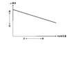
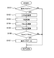
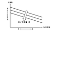
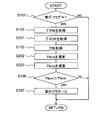
- 1 is a diagram showing a schematic configuration of an internal combustion engine to which the present invention is applied. It is a figure which shows correlation with PM deposition amount and an upper limit. It is a flowchart which shows the process routine which ECU performs, when the execution conditions of active control are satisfied in a 1st Example. It is a figure which shows correlation with PM deposition amount, SOF deposition amount, and an upper limit. It is a flowchart which shows the process routine which ECU performs, when the execution conditions of active control are satisfied in a 2nd Example. It is a flowchart which shows the process routine performed by ECU during the execution period of a 1st process.
- FIG. 1 is a diagram showing a schematic configuration of an internal combustion engine to which the present invention is applied.
- An internal combustion engine 1 shown in FIG. 1 is a 4-stroke cycle spark ignition internal combustion engine (gasoline engine) having a plurality of cylinders. In FIG. 1, only one cylinder among a plurality of cylinders is shown.
- a piston 3 is slidably mounted in each cylinder 2 of the internal combustion engine 1.
- the piston 3 is connected to an output shaft (crankshaft) (not shown) via a connecting rod 4.
- Each cylinder 2 is provided with a fuel injection valve 5 for injecting fuel into the cylinder 2 and a spark plug 6 for generating a spark in the cylinder 2.
- the inside of the cylinder 2 communicates with the intake port 7 and the exhaust port 8.
- the opening end of the intake port 7 in the cylinder 2 is opened and closed by an intake valve 9.
- An open end of the exhaust port 8 in the cylinder 2 is opened and closed by an exhaust valve 10.
- the intake valve 9 and the exhaust valve 10 are respectively opened and closed by an intake cam and an exhaust cam (not shown).
- the intake port 7 communicates with the intake passage 70.
- a throttle valve 71 is disposed in the intake passage 70.
- An air flow meter 72 is disposed in the intake passage 70 upstream of the throttle valve 71.
- the exhaust port 8 communicates with the exhaust passage 80.
- a particulate filter 81 for collecting particulate matter (PM) in the exhaust is disposed in the exhaust passage 80.
- the particulate filter 81 is, for example, a wall flow type filter formed of a porous base material. Note that the particulates upstream of the exhaust passage 80 from the filter 81 or the exhaust downstream of passage 80 from the particulate filter 81, the exhaust purifying catalyst (e.g., oxidation catalyst, three-way catalyst, storage-reduction NO X catalyst, selective reduction exhaust purification apparatus comprising a mold NO X catalyst, etc.) may be placed.
- the exhaust purifying catalyst e.g., oxidation catalyst, three-way catalyst, storage-reduction NO X catalyst, selective reduction exhaust purification apparatus comprising a mold NO X catalyst, etc.
- the internal combustion engine 1 configured as described above is provided with an ECU 20.
- the ECU 20 is an electronic control unit that includes a CPU, a ROM, a RAM, a backup RAM, and the like.
- the ECU 20 receives detection signals from various sensors such as the water temperature sensor 11, the crank position sensor 21, the accelerator position sensor 22, the differential pressure sensor 82, and the exhaust temperature sensor 83. Yes.
- the air flow meter 72 outputs an electrical signal correlated with the amount (mass) of the intake air flowing through the intake passage 70.
- the water temperature sensor 11 outputs an electrical signal correlated with the temperature of the cooling water circulating through the internal combustion engine 1.
- the crank position sensor 21 outputs a signal correlated with the rotational position of the crankshaft.
- the accelerator position sensor 22 outputs an electrical signal correlated with an operation amount (accelerator opening) of an accelerator pedal (not shown).
- the differential pressure sensor 82 outputs an electrical signal that correlates with the difference between the exhaust pressure upstream of the particulate filter 81 and the exhaust pressure downstream of the particulate filter 81 (front-rear differential pressure).
- the exhaust temperature sensor 83 is disposed in the exhaust passage 80 downstream of the particulate filter 81 and outputs an electrical signal correlated with the temperature of the exhaust gas flowing out from the particulate filter 81.
- the ECU 20 is electrically connected to various devices such as the fuel injection valve 5, the spark plug 6, and the throttle valve 71, and controls various devices based on the output signals of the various sensors described above.
- the ECU 20 performs particulates in addition to known controls such as fuel injection control and ignition control in accordance with the operating state of the internal combustion engine 1 determined by output signals from the crank position sensor 21, the accelerator position sensor 22, the air flow meter 72, and the like.
- a process (first process) accompanied by a temperature rise of the filter 81 is executed.
- the “first process” is a process executed for the purpose of detecting an abnormality of the exhaust gas purification device, calculating a learning value used for air-fuel ratio feedback control, or raising the exhaust gas temperature.
- the first process is active control in which the air-fuel ratio of the air-fuel mixture burned in each cylinder 2 of the internal combustion engine 1 is switched between rich and lean, and combustion is performed in some cylinders 2 of the internal combustion engine 1.
- Inter-cylinder imbalance control that makes the air-fuel ratio of the air-fuel mixture rich and at the same time makes the air-fuel ratio of the air-fuel mixture burned in the remaining cylinders 2 lean, or ignition delay that retards the ignition timing of each cylinder 2 of the internal combustion engine 1 For example, angle control.
- active control is executed as the first process will be described.
- the active control when the air-fuel ratio of the air-fuel mixture is made rich, the amount of PM contained in the exhaust gas increases, so the PM deposition amount of the particulate filter 81 tends to increase. Further, in the configuration in which the catalyst having oxidizing ability is arranged upstream of the particulate filter 81 or the configuration in which the catalyst is supported by the particulate filter 81, the catalyst is oxidized by the catalyst when the air-fuel ratio of the air-fuel mixture is made rich. Since the amount of unburned HC that is generated increases, the temperature of the catalyst and the exhaust gas flowing out from the catalyst rises. As a result, the temperature of the particulate filter 81 increases.
- the process in which the exhaust discharged from the internal combustion engine 1 is in an oxygen-excess state is, for example, a process of stopping the operation of the fuel injection valve 5 (fuel cut) during the deceleration operation of the internal combustion engine 1 or a process of reducing the internal combustion engine 1 This is a process for leaning the air-fuel ratio of the air-fuel mixture during medium load operation.
- the spark purification device for the spark ignition type internal combustion engine of the present embodiment was not executed.
- the “upper limit value” is a minimum value of the temperature at which the particulate filter 81 is considered to overheat when the second process is executed in a state where the temperature of the particulate filter 81 is higher than the upper limit value.
- the “upper limit value” here means that if the temperature of the particulate filter 81 at the start of execution of the second process is equal to or lower than the upper limit value, the particulate filter 81 will rise excessively even if the second process is executed. This is the maximum temperature that is considered not to be warm.
- the amount of increase in the temperature of the particulate filter 81 when the second process is executed tends to increase as the temperature of the particulate filter 81 at the start of the execution of the second process increases.
- the upper limit value is set to a lower temperature as the PM deposition amount of the particulate filter 81 increases.
- the PM accumulation amount in FIG. 2 is the PM accumulation amount when the active control execution condition is satisfied.
- the “temperature predicted value” here is the maximum temperature that the temperature of the particulate filter 81 can take in the period from the start of execution of active control to the end of execution. Note that the relationship between the temperature of the particulate filter 81 when the active control execution condition is satisfied, the PM accumulation amount of the particulate filter 81 when the condition is satisfied, and the predicted temperature value is obtained by using experiments in advance. You may obtain
- the ECU 20 determines whether or not the predicted temperature value is equal to or lower than the upper limit value.
- the ECU 20 executes active control.
- the ECU 20 does not execute active control.
- the ECU 20 prohibits the execution of the active control without prohibiting the execution of the second process when the particulate filter 81 is predicted to overheat due to the execution of the active control and the second process. As a result, it is possible to obtain the effect of reducing the fuel consumption due to the execution of the second process while suppressing the excessive temperature rise of the particulate filter 81.
- FIG. 3 is a flowchart showing a processing routine executed by the ECU 20 when the active control execution condition is satisfied, and is stored in advance in the ROM or the like of the ECU 20.
- the ECU 20 first determines whether or not the value of the active control execution flag is “1” in the processing of S101.
- the execution flag is a storage area set in the RAM of the ECU 20 or the backup RAM. Such an execution flag is set to “1” when the active control execution condition is satisfied, and is reset to “0” when the execution of the active control is completed. If a negative determination is made in the process of S101, the ECU 20 ends the execution of this routine. On the other hand, if an affirmative determination is made in the process of S101, the ECU 20 proceeds to the process of S102.
- the ECU 20 acquires the PM accumulation amount ⁇ PM of the particulate filter 81.
- the PM accumulation amount ⁇ PM of the particulate filter 81 can be obtained by a known method.
- the ECU 20 may calculate the PM accumulation amount ⁇ PM using the operation history (fuel injection amount, intake air amount, etc.) of the internal combustion engine 1 as a parameter, or the PM accumulation amount ⁇ PM using the measurement value of the differential pressure sensor 82 as a parameter. May be calculated.
- the ECU 20 acquires the temperature Tf of the particulate filter 81. Specifically, the ECU 20 may calculate the temperature Tf of the particulate filter 81 using the operation history (fuel injection amount, intake air amount, etc.) of the internal combustion engine 1 as a parameter, or the measured value of the exhaust temperature sensor 83 is calculated. Alternatively, the temperature Tf of the particulate filter 81 may be substituted.
- the ECU 20 can execute the second process while avoiding the excessive temperature rise of the particulate filter 81 based on the PM accumulation amount ⁇ PM acquired in S102 and the correlation of FIG.
- the temperature (upper limit value) Tflmt of the possible particulate filter 81 is calculated.
- the ECU 20 calculates the predicted temperature value Tfpre using the PM accumulation amount ⁇ PM acquired in the processes of S102 and S103 and the temperature Tf of the particulate filter 81 as parameters. At this time, the temperature predicted value Tfpre is set to a higher temperature as the PM deposition amount ⁇ PM increases and / or as the temperature Tf increases.
- the “calculation means” according to the present invention is realized.
- the ECU 20 compares the upper limit value Tflmt calculated in the processes of S104 and S105 with the predicted temperature value Tfpre. Specifically, the ECU 20 determines whether or not the predicted temperature value Tfpre is greater than the upper limit value Tflmt.
- the ECU 20 If an affirmative determination is made in the processing of S106 (Tfpre> Tflmt), the ECU 20 resets the active control execution flag to “0”. In this case, since active control is not executed, the temperature of the particulate filter 81 when the second process is executed is unlikely to exceed the upper limit value Tflmt. As a result, it is possible to obtain an effect of reducing fuel consumption by executing the second process while avoiding excessive temperature rise of the particulate filter 81. On the other hand, when a negative determination is made in the process of S106 (Tfpre ⁇ Tflmt), the ECU 20 ends the execution of this routine. In this case, since the active control execution flag is set to “1”, the active control is executed. However, the temperature of the particulate filter 81 is unlikely to exceed the upper limit value Tflmt during or after the active control is executed. It becomes difficult to do.
- the prohibiting means according to the present invention is realized by the ECU 20 executing the processing of S105 to S107.
- the execution of the active control is prohibited and the execution of the second process is permitted. Is done. In this case, it is possible to obtain the effect of reducing the fuel consumption by executing the second process while suppressing the excessive temperature rise of the particulate filter 81.
- the particulate filter 81 is predicted to overheat due to the execution of the active control and the second process, it is possible to suppress the overheating of the particulate filter 81 while avoiding an increase in fuel consumption. it can.
- the active control is exemplified as the “first process” according to the present invention.
- the cylinder imbalance control or the ignition retard control may be performed as the first process.
- the inter-cylinder imbalance control When the inter-cylinder imbalance control is performed, the amounts of PM, unburned HC, and oxygen contained in the exhaust gas increase as in the case where the active control is performed. In that case, PM is easily oxidized in the particulate filter 81. As a result, the temperature of the particulate filter 81 may become higher than the upper limit value Tflmt.
- the processing routine as shown in FIG. 3 is executed when the execution condition of the inter-cylinder imbalance control is satisfied, the particulate filter 81 is excessively caused by the execution of the inter-cylinder imbalance control and the second processing.
- the ignition retard control when executed, the amount of PM and unburned HC contained in the exhaust increases, and the temperature of the exhaust increases. As a result, the temperature of the particulate filter 81 may become higher than the upper limit value Tflmt, and the PM deposition amount ⁇ PM when the second process is executed may increase.
- the processing routine as shown in FIG. 3 is executed when the execution condition of the ignition retard control is satisfied, the particulate filter 81 is overheated by the execution of the ignition retard control and the second processing. If predicted, the execution of the ignition retard control is prohibited and the execution of the second process is permitted. As a result, it is possible to avoid an excessive increase in temperature of the particulate filter 81 while avoiding an increase in fuel consumption.
- Example 2 a second embodiment of the exhaust gas purification apparatus for a spark ignition type internal combustion engine according to the present invention will be described with reference to FIGS.
- a configuration different from that of the first embodiment will be described, and description of the same configuration will be omitted.
- the difference between the first embodiment described above and the present embodiment is that the component ratio of PM deposited on the particulate filter 81 is taken into account when determining the upper limit value. Specifically, the amount of organic soluble components (SOF: Soluble Organic Organic Fraction) contained in the PM deposited on the particulate filter 81 is taken into consideration.
- SOF Soluble Organic Organic Fraction
- SOF deposition amount the amount of SOF contained in the PM deposited on the particulate filter 81 (hereinafter referred to as “SOF deposition amount”) increases, the temperature rise amount of the particulate filter 81 when the second process is executed. Will increase. Therefore, as shown in FIG. 4, the upper limit value decreases as the PM deposition amount and the SOF deposition amount increase.
- the exhaust gas purification apparatus for the spark ignition type internal combustion engine determines the upper limit value by using the amount of SOF accumulated in the particulate filter 81 (SOF accumulation amount) as a parameter in addition to the PM accumulation amount. I made it. It should be noted that the amount of SOF (unburned HC) contained in the exhaust gas is larger when the first process such as active control, inter-cylinder imbalance control, or ignition delay angle control is performed than when the first process is not performed. Therefore, it is desirable that the SOF deposition amount used as a parameter when calculating the upper limit value is the SOF deposition amount when it is assumed that the first process is performed.
- the SOF deposition amount when it is assumed that the first processing is executed is the SOF deposition amount when the execution condition of the first processing is satisfied, and the amount of SOF deposited on the particulate filter 81 during the execution of the first processing. (Hereinafter referred to as “SOF additional amount”).
- the SOF accumulation amount when the execution condition of the first process is satisfied is the SOF emission amount (internal combustion engine) calculated using the operation state (target air-fuel ratio, target ignition timing, cooling water temperature, etc.) at any time of the internal combustion engine 1 as a parameter. 1) can be obtained by integrating the amount of SOF discharged from 1.
- the additional amount of SOF is such that the target air-fuel ratio when the air-fuel ratio of the air-fuel mixture combusted in each cylinder 2 is made rich is lower (the degree of richness is higher) and is active In the control, the total time for which the air-fuel ratio of the air-fuel mixture is made rich (hereinafter referred to as “total rich time”) becomes longer as it becomes longer. Therefore, the SOF addition amount when it is assumed that active control is executed can be calculated using the target air-fuel ratio and the total rich time as parameters.
- the additional amount of SOF is such that the lower the target air-fuel ratio of the cylinder 2 at which the air-fuel ratio of the air-fuel mixture becomes richer, and the longer the execution time of the inter-cylinder imbalance control. It will increase. Therefore, the SOF addition amount when it is assumed that the inter-cylinder imbalance control is executed can be calculated using the target air-fuel ratio and the execution time of the inter-cylinder imbalance control as parameters.
- the SOF addition amount increases as the target ignition timing is delayed (the retard amount of the ignition timing is increased) and the execution time of the ignition retard control is increased. Therefore, the additional amount of SOF when it is assumed that the ignition retard control is executed can be calculated using the target ignition timing and the execution time of the ignition retard control as parameters.
- the ECU 20 When the SOF accumulation amount when the execution condition of the first process is satisfied and the SOF addition amount when it is assumed that the first process is executed are calculated, the ECU 20 adds the SOF accumulation amount and the SOF addition amount. Thus, the SOF deposition amount when it is assumed that the first process is executed is calculated. Then, the ECU 20 calculates the upper limit value based on the PM accumulation amount, the SOF accumulation amount, and the correlation as shown in FIG. The ECU 20 may calculate an upper limit value based on the PM accumulation amount and the correlation as shown in FIG. 2 and correct the upper limit value according to the SOF accumulation amount. In that case, the upper limit value may be corrected to a lower temperature as the SOF deposition amount increases.
- the temperature (temperature predicted value) of the particulate filter 81 when it is assumed that the first process is executed may also change depending on the SOF deposition amount. That is, as the SOF deposition amount increases when the first process is performed, the predicted temperature value increases. Therefore, the ECU 20 may calculate the predicted temperature value using the temperature of the particulate filter 81, the PM accumulation amount, and the SOF accumulation amount as parameters. The ECU 20 may calculate a predicted temperature value based on the temperature of the particulate filter 81 and the PM deposition amount, and correct the predicted temperature value according to the SOF deposition amount. In this case, the temperature predicted value may be corrected to a higher temperature as the SOF deposition amount increases.
- the particulate filter 81 is excessively heated when it is assumed that the second process is performed during or after the first process. It is possible to more accurately determine (predict) whether or not. As a result, the excessive temperature rise of the particulate filter 81 is more reliably suppressed.
- FIG. 5 is a flowchart showing a processing routine executed by the ECU 20 when the execution condition of the first processing is satisfied, and is stored in advance in the ROM or the like of the ECU 20.
- the same reference numerals are assigned to the same processes as those in the processing routine of the first embodiment described above (see FIG. 3).
- the ECU 20 executes the process of S201 after executing the process of S102.
- the ECU 20 calculates the SOF accumulation amount ⁇ SOF when it is assumed that the first process is executed. Specifically, as described above, the ECU 20 adds the SOF accumulation amount at the time when the execution condition of the first process is satisfied and the SOF addition amount when it is assumed that the first process is executed, The SOF deposition amount ⁇ SOF is calculated.
- the ECU 20 executes the process of S103 after executing the process of S201, and then executes the process of S202.
- the ECU 20 sets the upper limit based on the PM accumulation amount ⁇ PM acquired in the process of S102, the SOF accumulation amount ⁇ SOF acquired in the process of S201, and the correlation shown in FIG.
- the value Tflmt is calculated.
- the ECU20 performs the process of S203 after performing the process of S202.
- the ECU 20 obtains the PM accumulation amount ⁇ PM obtained in the process of S102, the SOF accumulation amount ⁇ SOF obtained in the process of S201, the temperature Tf of the particulate filter 81 obtained in the process of S103, Is used as a parameter to calculate the predicted temperature value Tfpre.
- the correction means according to the present invention is realized by the ECU 20 executing the processes of S202 and S203.
- ECU20 performs the process of S106 thru
- the temperature increase rate of the particulate filter 81 during the first process is larger than expected. Is also possible. In such a case, the temperature of the particulate filter 81 may be higher than the upper limit value by executing the first process.
- the exhaust gas purification apparatus for the spark ignition type internal combustion engine of the present embodiment predicts the temperature of the particulate filter 81 after a predetermined time during the execution of the first process, and the predicted temperature is higher than the upper limit value. In such a case, the execution of the first process is terminated (stopped).
- the ECU 20 calculates the temperature increase amount (slope) per unit time from the temperature increase amount from the start of execution of the first process to the present time.
- the ECU 20 calculates (estimates) the temperature of the particulate filter 81 (hereinafter referred to as “sub-temperature predicted value”) when a predetermined time has elapsed from the present time.
- the ECU 20 ends the execution of the first process when the sub temperature predicted value is higher than the upper limit value.
- the particulate filter 81 when it is determined that the predicted sub-temperature is higher than the upper limit value, it is considered that the temperature of the particulate filter 81 at that time has risen to the vicinity of the upper limit value. In such a case, even if the execution of the first process is terminated, the particulate filter 81 may overheat when the second process is executed.
- the exhaust gas purification apparatus for a spark ignition type internal combustion engine reduces the temperature of the particulate filter 81 when the execution of the first process is terminated during the execution of the first process ( Cooling process).
- the ECU 20 at least one of a process for advancing the ignition timing, a process for increasing the fuel injection amount (a process for enriching the air-fuel ratio of the air-fuel mixture), and a process for increasing the intake air amount. Run one.
- the ignition timing is advanced, compared with the case where the ignition timing is not advanced, the combustion end timing of the air-fuel mixture is advanced, so that the temperature of the exhaust gas is lowered.
- the amount of oxygen contained in the exhaust gas is smaller than when the fuel injection amount is not increased. Therefore, the PM oxidation rate is reduced, and the temperature rise of the particulate filter 81 is mitigated.
- the intake air amount is increased, the amount of heat transferred from the particulate filter 81 to the exhaust gas is increased as compared with a case where the intake air amount is not increased, so that the temperature of the particulate filter 81 is lowered. Note that when the intake air amount is increased, the torque generated by the internal combustion engine 1 may change. Therefore, transmission downshifting may be used in combination.
- the excessive temperature rise of the particulate filter 81 can be more reliably suppressed after the execution of the first process and when the second process is executed. .
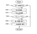
- FIG. 6 is a flowchart showing a processing routine that is repeatedly executed by the ECU 20 during the execution period of the first processing, and is a processing routine that is stored in the ROM of the ECU 20 in advance.
- the ECU 20 first determines whether or not the first processing is being executed in the processing of S301. When a negative determination is made in the process of S301, the ECU 20 once ends the execution of this routine. On the other hand, if an affirmative determination is made in the process of S301, the ECU 20 proceeds to the process of S302.
- the ECU 20 calculates the upper limit value Tflmt.
- the ECU 20 may calculate the upper limit value Tflmt using the current PM deposition amount ⁇ PM as a parameter, or may calculate the upper limit value Tflmt using the current PM deposition amount ⁇ PM and the SOF deposition amount ⁇ SOF as parameters. .
- the ECU 20 calculates the temperature (sub-temperature predicted value) Tfpsub of the particulate filter 81 when a predetermined time has elapsed from the present time. Specifically, the ECU 20 sets the difference between the temperature of the particulate filter 81 at the start of execution of the first process and the temperature of the particulate filter 81 at the current time, and the elapsed time from the start of execution of the first process to the current time as parameters. As described above, the amount of temperature increase per unit time (temperature Tf increase rate) is calculated.
- the ECU 20 calculates the temperature (sub-temperature predicted value) Tfpsub of the particulate filter 81 when a predetermined time has elapsed from the current time, using the temperature increase rate as a parameter. It should be noted that the “sub-calculation means” according to the present invention is realized when the ECU 20 executes the process of S303.
- the ECU 20 compares the upper limit value Tflmt calculated in the process of S302 with the sub temperature predicted value Tfpsub calculated in the process of S303. Specifically, the ECU 20 determines whether or not the sub temperature predicted value Tfpsub is higher than the upper limit value Tflmt. When a negative determination is made in the process of S304, the ECU 20 once ends the execution of this routine. In that case, the execution of the first process is continued. On the other hand, when an affirmative determination is made in the process of S304, the ECU 20 proceeds to the process of S305.
- the ECU 20 ends the execution of the first process.
- the “stop unit” according to the present invention is realized. If the time when the temperature of the particulate filter 81 reaches the upper limit value Tflmt is after the end time of the first process, the execution of the first process may be continued.
- the ECU 20 executes a cooling process. Specifically, the ECU 20 executes at least one of a process for advancing the ignition timing, a process for increasing the fuel injection amount, and a process for increasing the intake air amount (a process for shifting down the transmission). In that case, since the temperature of the particulate filter 81 is lowered, it is difficult for the particulate filter 81 to overheat at the time of the subsequent execution of the second process.
- the “cooling means” according to the present invention is realized.
- the excessive temperature rise of the particulate filter 81 can be suppressed.
- the particulate filter 81 is cooled, so that the temperature of the particulate filter 81 is excessively raised during the subsequent execution of the second process. Can be avoided more reliably.
- the upper limit value Tflmt is the exhaust system after the particulate filter 81 when the second process is executed in a state where the temperature of the particulate filter 81 is higher than the upper limit value.
- Exhaust system parts for example, a catalyst carried on the particulate filter 81, a catalyst arranged downstream from the particulate filter 81, or a sensor arranged downstream from the particulate filter 81
- it may be the minimum value of the temperature considered. In that case, it is possible to suppress an excessive increase in temperature of the exhaust system parts while suppressing an increase in fuel consumption.
Landscapes
- Engineering & Computer Science (AREA)
- Chemical & Material Sciences (AREA)
- Combustion & Propulsion (AREA)
- Mechanical Engineering (AREA)
- General Engineering & Computer Science (AREA)
- Theoretical Computer Science (AREA)
- Signal Processing (AREA)
- Processes For Solid Components From Exhaust (AREA)
Abstract
Le problème décrit par la présente invention est de supprimer la surchauffe d'un filtre à particules et de pièces d'un système d'échappement, tout en supprimant également une augmentation de la consommation de carburant dans un moteur à combustion interne à allumage par étincelles dans lequel un filtre à particules est disposé dans un passage d'échappement, un processus accompagnant une augmentation de température dans le filtre à particules étant exécuté. La solution selon l'invention porte sur un dispositif d'épuration de gaz d'échappement pour un moteur à combustion interne à allumage par étincelles, qui comporte : un filtre à particules disposé dans un passage d'échappement ; un premier moyen de traitement destiné à exécuter un premier processus qui accompagne une augmentation de température dans le filtre à particules ; et un second moyen de traitement destiné à exécuter un second processus lorsque les gaz d'échappement évacués depuis le moteur à combustion interne sont dans un état d'excès d'oxygène. Si la température du filtre à particules en charge de l'exécution du premier processus dépasse la valeur limite supérieure pour la température à laquelle le second processus peut être exécuté, l'exécution du premier processus est empêchée.
Priority Applications (1)
| Application Number | Priority Date | Filing Date | Title |
|---|---|---|---|
| PCT/JP2013/055688 WO2014132443A1 (fr) | 2013-03-01 | 2013-03-01 | Dispositif d'épuration de gaz d'échappement pour moteur à combustion interne à allumage par étincelles |
Applications Claiming Priority (1)
| Application Number | Priority Date | Filing Date | Title |
|---|---|---|---|
| PCT/JP2013/055688 WO2014132443A1 (fr) | 2013-03-01 | 2013-03-01 | Dispositif d'épuration de gaz d'échappement pour moteur à combustion interne à allumage par étincelles |
Publications (1)
| Publication Number | Publication Date |
|---|---|
| WO2014132443A1 true WO2014132443A1 (fr) | 2014-09-04 |
Family
ID=51427742
Family Applications (1)
| Application Number | Title | Priority Date | Filing Date |
|---|---|---|---|
| PCT/JP2013/055688 Ceased WO2014132443A1 (fr) | 2013-03-01 | 2013-03-01 | Dispositif d'épuration de gaz d'échappement pour moteur à combustion interne à allumage par étincelles |
Country Status (1)
| Country | Link |
|---|---|
| WO (1) | WO2014132443A1 (fr) |
Cited By (4)
| Publication number | Priority date | Publication date | Assignee | Title |
|---|---|---|---|---|
| JP2018062199A (ja) * | 2016-10-11 | 2018-04-19 | トヨタ自動車株式会社 | ハイブリッド自動車 |
| JP2019070344A (ja) * | 2017-10-06 | 2019-05-09 | トヨタ自動車株式会社 | 内燃機関の制御装置 |
| CN114542244A (zh) * | 2020-11-11 | 2022-05-27 | 丰田自动车株式会社 | 内燃机的控制装置及方法 |
| JP2023082418A (ja) * | 2021-12-02 | 2023-06-14 | トヨタ自動車株式会社 | 車両の制御装置 |
Citations (5)
| Publication number | Priority date | Publication date | Assignee | Title |
|---|---|---|---|---|
| JP2008106709A (ja) * | 2006-10-27 | 2008-05-08 | Mazda Motor Corp | ディーゼルエンジンの排気浄化装置 |
| JP2009074426A (ja) * | 2007-09-20 | 2009-04-09 | Toyota Motor Corp | 内燃機関の制御装置 |
| JP2009167839A (ja) * | 2008-01-11 | 2009-07-30 | Toyota Motor Corp | 内燃機関の排気浄化装置 |
| JP2009215933A (ja) * | 2008-03-10 | 2009-09-24 | Toyota Motor Corp | 内燃機関の制御装置 |
| JP2012219732A (ja) * | 2011-04-11 | 2012-11-12 | Toyota Motor Corp | Pmフィルタ及びpmフィルタの再生方法 |
-
2013
- 2013-03-01 WO PCT/JP2013/055688 patent/WO2014132443A1/fr not_active Ceased
Patent Citations (5)
| Publication number | Priority date | Publication date | Assignee | Title |
|---|---|---|---|---|
| JP2008106709A (ja) * | 2006-10-27 | 2008-05-08 | Mazda Motor Corp | ディーゼルエンジンの排気浄化装置 |
| JP2009074426A (ja) * | 2007-09-20 | 2009-04-09 | Toyota Motor Corp | 内燃機関の制御装置 |
| JP2009167839A (ja) * | 2008-01-11 | 2009-07-30 | Toyota Motor Corp | 内燃機関の排気浄化装置 |
| JP2009215933A (ja) * | 2008-03-10 | 2009-09-24 | Toyota Motor Corp | 内燃機関の制御装置 |
| JP2012219732A (ja) * | 2011-04-11 | 2012-11-12 | Toyota Motor Corp | Pmフィルタ及びpmフィルタの再生方法 |
Cited By (6)
| Publication number | Priority date | Publication date | Assignee | Title |
|---|---|---|---|---|
| JP2018062199A (ja) * | 2016-10-11 | 2018-04-19 | トヨタ自動車株式会社 | ハイブリッド自動車 |
| JP2019070344A (ja) * | 2017-10-06 | 2019-05-09 | トヨタ自動車株式会社 | 内燃機関の制御装置 |
| CN114542244A (zh) * | 2020-11-11 | 2022-05-27 | 丰田自动车株式会社 | 内燃机的控制装置及方法 |
| CN114542244B (zh) * | 2020-11-11 | 2023-09-08 | 丰田自动车株式会社 | 内燃机的控制装置及方法 |
| JP2023082418A (ja) * | 2021-12-02 | 2023-06-14 | トヨタ自動車株式会社 | 車両の制御装置 |
| JP7600969B2 (ja) | 2021-12-02 | 2024-12-17 | トヨタ自動車株式会社 | 車両の制御装置 |
Similar Documents
| Publication | Publication Date | Title |
|---|---|---|
| CN105840275B (zh) | 用于维持dfso的方法和系统 | |
| US8464522B2 (en) | Control apparatus for internal combustion engine | |
| JP5831556B2 (ja) | 内燃機関の燃料噴射システム | |
| JP5131362B2 (ja) | 内燃機関の制御装置 | |
| JP2009074426A (ja) | 内燃機関の制御装置 | |
| JP5765495B2 (ja) | 可変圧縮比内燃機関の制御装置および制御方法 | |
| US9441524B2 (en) | Methods and systems for an exhaust gas treatment system | |
| JP5278454B2 (ja) | 多気筒内燃機関の気筒間空燃比ばらつき異常検出装置 | |
| JP5664884B2 (ja) | 内燃機関の空燃比制御装置 | |
| JP6363742B1 (ja) | 触媒の劣化判定装置 | |
| WO2014132443A1 (fr) | Dispositif d'épuration de gaz d'échappement pour moteur à combustion interne à allumage par étincelles | |
| JP2014101863A (ja) | 内燃機関の異常燃焼判定装置 | |
| JP4508045B2 (ja) | 内燃機関の制御装置 | |
| JP2004076668A (ja) | 内燃機関の制御装置 | |
| JP4840240B2 (ja) | 内燃機関の制御システム | |
| JP2015124714A (ja) | エンジンの制御装置 | |
| JP2008267294A (ja) | 内燃機関の制御システム | |
| JP2014145271A (ja) | 火花点火式内燃機関の排気浄化装置 | |
| JP2014156807A (ja) | 内燃機関の排気浄化装置 | |
| JP5690182B2 (ja) | 内燃機関の制御装置 | |
| JP2005016396A (ja) | 内燃機関の触媒暖機システム | |
| JP2009257211A (ja) | 内燃機関の制御システム | |
| JP2011012599A (ja) | 内燃機関の排ガス浄化装置 | |
| JP5327721B2 (ja) | 内燃機関の排気浄化システム | |
| JP2008223672A (ja) | 内燃機関の排気エミッション低減システム |
Legal Events
| Date | Code | Title | Description |
|---|---|---|---|
| 121 | Ep: the epo has been informed by wipo that ep was designated in this application |
Ref document number: 13876388 Country of ref document: EP Kind code of ref document: A1 |
|
| NENP | Non-entry into the national phase |
Ref country code: DE |
|
| 122 | Ep: pct application non-entry in european phase |
Ref document number: 13876388 Country of ref document: EP Kind code of ref document: A1 |
|
| NENP | Non-entry into the national phase |
Ref country code: JP |