WO2014132764A1 - ラミネート方法および積層体 - Google Patents
ラミネート方法および積層体 Download PDFInfo
- Publication number
- WO2014132764A1 WO2014132764A1 PCT/JP2014/052695 JP2014052695W WO2014132764A1 WO 2014132764 A1 WO2014132764 A1 WO 2014132764A1 JP 2014052695 W JP2014052695 W JP 2014052695W WO 2014132764 A1 WO2014132764 A1 WO 2014132764A1
- Authority
- WO
- WIPO (PCT)
- Prior art keywords
- substrate
- nip
- adhesive
- support
- metallic substrate
- Prior art date
- Legal status (The legal status is an assumption and is not a legal conclusion. Google has not performed a legal analysis and makes no representation as to the accuracy of the status listed.)
- Ceased
Links
Images



Classifications
-
- B—PERFORMING OPERATIONS; TRANSPORTING
- B32—LAYERED PRODUCTS
- B32B—LAYERED PRODUCTS, i.e. PRODUCTS BUILT-UP OF STRATA OF FLAT OR NON-FLAT, e.g. CELLULAR OR HONEYCOMB, FORM
- B32B25/00—Layered products comprising a layer of natural or synthetic rubber
- B32B25/04—Layered products comprising a layer of natural or synthetic rubber comprising rubber as the main or only constituent of a layer, which is next to another layer of the same or of a different material
-
- B—PERFORMING OPERATIONS; TRANSPORTING
- B29—WORKING OF PLASTICS; WORKING OF SUBSTANCES IN A PLASTIC STATE IN GENERAL
- B29C—SHAPING OR JOINING OF PLASTICS; SHAPING OF MATERIAL IN A PLASTIC STATE, NOT OTHERWISE PROVIDED FOR; AFTER-TREATMENT OF THE SHAPED PRODUCTS, e.g. REPAIRING
- B29C65/00—Joining or sealing of preformed parts, e.g. welding of plastics materials; Apparatus therefor
- B29C65/78—Means for handling the parts to be joined, e.g. for making containers or hollow articles, e.g. means for handling sheets, plates, web-like materials, tubular articles, hollow articles or elements to be joined therewith; Means for discharging the joined articles from the joining apparatus
-
- B—PERFORMING OPERATIONS; TRANSPORTING
- B32—LAYERED PRODUCTS
- B32B—LAYERED PRODUCTS, i.e. PRODUCTS BUILT-UP OF STRATA OF FLAT OR NON-FLAT, e.g. CELLULAR OR HONEYCOMB, FORM
- B32B37/00—Methods or apparatus for laminating, e.g. by curing or by ultrasonic bonding
- B32B37/06—Methods or apparatus for laminating, e.g. by curing or by ultrasonic bonding characterised by the heating method
-
- B—PERFORMING OPERATIONS; TRANSPORTING
- B32—LAYERED PRODUCTS
- B32B—LAYERED PRODUCTS, i.e. PRODUCTS BUILT-UP OF STRATA OF FLAT OR NON-FLAT, e.g. CELLULAR OR HONEYCOMB, FORM
- B32B37/00—Methods or apparatus for laminating, e.g. by curing or by ultrasonic bonding
- B32B37/12—Methods or apparatus for laminating, e.g. by curing or by ultrasonic bonding characterised by using adhesives
-
- B—PERFORMING OPERATIONS; TRANSPORTING
- B32—LAYERED PRODUCTS
- B32B—LAYERED PRODUCTS, i.e. PRODUCTS BUILT-UP OF STRATA OF FLAT OR NON-FLAT, e.g. CELLULAR OR HONEYCOMB, FORM
- B32B7/00—Layered products characterised by the relation between layers; Layered products characterised by the relative orientation of features between layers, or by the relative values of a measurable parameter between layers, i.e. products comprising layers having different physical, chemical or physicochemical properties; Layered products characterised by the interconnection of layers
- B32B7/04—Interconnection of layers
- B32B7/12—Interconnection of layers using interposed adhesives or interposed materials with bonding properties
-
- B—PERFORMING OPERATIONS; TRANSPORTING
- B29—WORKING OF PLASTICS; WORKING OF SUBSTANCES IN A PLASTIC STATE IN GENERAL
- B29C—SHAPING OR JOINING OF PLASTICS; SHAPING OF MATERIAL IN A PLASTIC STATE, NOT OTHERWISE PROVIDED FOR; AFTER-TREATMENT OF THE SHAPED PRODUCTS, e.g. REPAIRING
- B29C65/00—Joining or sealing of preformed parts, e.g. welding of plastics materials; Apparatus therefor
- B29C65/02—Joining or sealing of preformed parts, e.g. welding of plastics materials; Apparatus therefor by heating, with or without pressure
- B29C65/14—Joining or sealing of preformed parts, e.g. welding of plastics materials; Apparatus therefor by heating, with or without pressure using wave energy, i.e. electromagnetic radiation, or particle radiation
- B29C65/1403—Joining or sealing of preformed parts, e.g. welding of plastics materials; Apparatus therefor by heating, with or without pressure using wave energy, i.e. electromagnetic radiation, or particle radiation characterised by the type of electromagnetic or particle radiation
- B29C65/1406—Ultraviolet [UV] radiation
-
- B—PERFORMING OPERATIONS; TRANSPORTING
- B29—WORKING OF PLASTICS; WORKING OF SUBSTANCES IN A PLASTIC STATE IN GENERAL
- B29C—SHAPING OR JOINING OF PLASTICS; SHAPING OF MATERIAL IN A PLASTIC STATE, NOT OTHERWISE PROVIDED FOR; AFTER-TREATMENT OF THE SHAPED PRODUCTS, e.g. REPAIRING
- B29C65/00—Joining or sealing of preformed parts, e.g. welding of plastics materials; Apparatus therefor
- B29C65/48—Joining or sealing of preformed parts, e.g. welding of plastics materials; Apparatus therefor using adhesives, i.e. using supplementary joining material; solvent bonding
- B29C65/4805—Joining or sealing of preformed parts, e.g. welding of plastics materials; Apparatus therefor using adhesives, i.e. using supplementary joining material; solvent bonding characterised by the type of adhesives
- B29C65/483—Reactive adhesives, e.g. chemically curing adhesives
- B29C65/4845—Radiation curing adhesives, e.g. UV light curing adhesives
-
- B—PERFORMING OPERATIONS; TRANSPORTING
- B29—WORKING OF PLASTICS; WORKING OF SUBSTANCES IN A PLASTIC STATE IN GENERAL
- B29C—SHAPING OR JOINING OF PLASTICS; SHAPING OF MATERIAL IN A PLASTIC STATE, NOT OTHERWISE PROVIDED FOR; AFTER-TREATMENT OF THE SHAPED PRODUCTS, e.g. REPAIRING
- B29C65/00—Joining or sealing of preformed parts, e.g. welding of plastics materials; Apparatus therefor
- B29C65/48—Joining or sealing of preformed parts, e.g. welding of plastics materials; Apparatus therefor using adhesives, i.e. using supplementary joining material; solvent bonding
- B29C65/52—Joining or sealing of preformed parts, e.g. welding of plastics materials; Apparatus therefor using adhesives, i.e. using supplementary joining material; solvent bonding characterised by the way of applying the adhesive
- B29C65/526—Joining or sealing of preformed parts, e.g. welding of plastics materials; Apparatus therefor using adhesives, i.e. using supplementary joining material; solvent bonding characterised by the way of applying the adhesive by printing or by transfer from the surfaces of elements carrying the adhesive, e.g. using brushes, pads, rollers, stencils or silk screens
-
- B—PERFORMING OPERATIONS; TRANSPORTING
- B29—WORKING OF PLASTICS; WORKING OF SUBSTANCES IN A PLASTIC STATE IN GENERAL
- B29C—SHAPING OR JOINING OF PLASTICS; SHAPING OF MATERIAL IN A PLASTIC STATE, NOT OTHERWISE PROVIDED FOR; AFTER-TREATMENT OF THE SHAPED PRODUCTS, e.g. REPAIRING
- B29C66/00—General aspects of processes or apparatus for joining preformed parts
- B29C66/01—General aspects dealing with the joint area or with the area to be joined
- B29C66/05—Particular design of joint configurations
- B29C66/10—Particular design of joint configurations particular design of the joint cross-sections
- B29C66/11—Joint cross-sections comprising a single joint-segment, i.e. one of the parts to be joined comprising a single joint-segment in the joint cross-section
- B29C66/112—Single lapped joints
- B29C66/1122—Single lap to lap joints, i.e. overlap joints
-
- B—PERFORMING OPERATIONS; TRANSPORTING
- B29—WORKING OF PLASTICS; WORKING OF SUBSTANCES IN A PLASTIC STATE IN GENERAL
- B29C—SHAPING OR JOINING OF PLASTICS; SHAPING OF MATERIAL IN A PLASTIC STATE, NOT OTHERWISE PROVIDED FOR; AFTER-TREATMENT OF THE SHAPED PRODUCTS, e.g. REPAIRING
- B29C66/00—General aspects of processes or apparatus for joining preformed parts
- B29C66/40—General aspects of joining substantially flat articles, e.g. plates, sheets or web-like materials; Making flat seams in tubular or hollow articles; Joining single elements to substantially flat surfaces
- B29C66/41—Joining substantially flat articles ; Making flat seams in tubular or hollow articles
- B29C66/45—Joining of substantially the whole surface of the articles
-
- B—PERFORMING OPERATIONS; TRANSPORTING
- B29—WORKING OF PLASTICS; WORKING OF SUBSTANCES IN A PLASTIC STATE IN GENERAL
- B29C—SHAPING OR JOINING OF PLASTICS; SHAPING OF MATERIAL IN A PLASTIC STATE, NOT OTHERWISE PROVIDED FOR; AFTER-TREATMENT OF THE SHAPED PRODUCTS, e.g. REPAIRING
- B29C66/00—General aspects of processes or apparatus for joining preformed parts
- B29C66/70—General aspects of processes or apparatus for joining preformed parts characterised by the composition, physical properties or the structure of the material of the parts to be joined; Joining with non-plastics material
- B29C66/71—General aspects of processes or apparatus for joining preformed parts characterised by the composition, physical properties or the structure of the material of the parts to be joined; Joining with non-plastics material characterised by the composition of the plastics material of the parts to be joined
-
- B—PERFORMING OPERATIONS; TRANSPORTING
- B29—WORKING OF PLASTICS; WORKING OF SUBSTANCES IN A PLASTIC STATE IN GENERAL
- B29C—SHAPING OR JOINING OF PLASTICS; SHAPING OF MATERIAL IN A PLASTIC STATE, NOT OTHERWISE PROVIDED FOR; AFTER-TREATMENT OF THE SHAPED PRODUCTS, e.g. REPAIRING
- B29C66/00—General aspects of processes or apparatus for joining preformed parts
- B29C66/70—General aspects of processes or apparatus for joining preformed parts characterised by the composition, physical properties or the structure of the material of the parts to be joined; Joining with non-plastics material
- B29C66/73—General aspects of processes or apparatus for joining preformed parts characterised by the composition, physical properties or the structure of the material of the parts to be joined; Joining with non-plastics material characterised by the intensive physical properties of the material of the parts to be joined, by the optical properties of the material of the parts to be joined, by the extensive physical properties of the parts to be joined, by the state of the material of the parts to be joined or by the material of the parts to be joined being a thermoplastic or a thermoset
- B29C66/731—General aspects of processes or apparatus for joining preformed parts characterised by the composition, physical properties or the structure of the material of the parts to be joined; Joining with non-plastics material characterised by the intensive physical properties of the material of the parts to be joined, by the optical properties of the material of the parts to be joined, by the extensive physical properties of the parts to be joined, by the state of the material of the parts to be joined or by the material of the parts to be joined being a thermoplastic or a thermoset characterised by the intensive physical properties of the material of the parts to be joined
- B29C66/7316—Surface properties
- B29C66/73161—Roughness or rugosity
- B29C66/73162—Roughness or rugosity of different roughness or rugosity, i.e. the roughness or rugosity of the surface of one of the parts to be joined being different from the roughness or rugosity of the surface of the other part
-
- B—PERFORMING OPERATIONS; TRANSPORTING
- B29—WORKING OF PLASTICS; WORKING OF SUBSTANCES IN A PLASTIC STATE IN GENERAL
- B29C—SHAPING OR JOINING OF PLASTICS; SHAPING OF MATERIAL IN A PLASTIC STATE, NOT OTHERWISE PROVIDED FOR; AFTER-TREATMENT OF THE SHAPED PRODUCTS, e.g. REPAIRING
- B29C66/00—General aspects of processes or apparatus for joining preformed parts
- B29C66/70—General aspects of processes or apparatus for joining preformed parts characterised by the composition, physical properties or the structure of the material of the parts to be joined; Joining with non-plastics material
- B29C66/73—General aspects of processes or apparatus for joining preformed parts characterised by the composition, physical properties or the structure of the material of the parts to be joined; Joining with non-plastics material characterised by the intensive physical properties of the material of the parts to be joined, by the optical properties of the material of the parts to be joined, by the extensive physical properties of the parts to be joined, by the state of the material of the parts to be joined or by the material of the parts to be joined being a thermoplastic or a thermoset
- B29C66/733—General aspects of processes or apparatus for joining preformed parts characterised by the composition, physical properties or the structure of the material of the parts to be joined; Joining with non-plastics material characterised by the intensive physical properties of the material of the parts to be joined, by the optical properties of the material of the parts to be joined, by the extensive physical properties of the parts to be joined, by the state of the material of the parts to be joined or by the material of the parts to be joined being a thermoplastic or a thermoset characterised by the optical properties of the material of the parts to be joined, e.g. fluorescence, phosphorescence
- B29C66/7336—General aspects of processes or apparatus for joining preformed parts characterised by the composition, physical properties or the structure of the material of the parts to be joined; Joining with non-plastics material characterised by the intensive physical properties of the material of the parts to be joined, by the optical properties of the material of the parts to be joined, by the extensive physical properties of the parts to be joined, by the state of the material of the parts to be joined or by the material of the parts to be joined being a thermoplastic or a thermoset characterised by the optical properties of the material of the parts to be joined, e.g. fluorescence, phosphorescence at least one of the parts to be joined being opaque, transparent or translucent to visible light
- B29C66/73365—General aspects of processes or apparatus for joining preformed parts characterised by the composition, physical properties or the structure of the material of the parts to be joined; Joining with non-plastics material characterised by the intensive physical properties of the material of the parts to be joined, by the optical properties of the material of the parts to be joined, by the extensive physical properties of the parts to be joined, by the state of the material of the parts to be joined or by the material of the parts to be joined being a thermoplastic or a thermoset characterised by the optical properties of the material of the parts to be joined, e.g. fluorescence, phosphorescence at least one of the parts to be joined being opaque, transparent or translucent to visible light at least one of the parts to be joined being transparent or translucent to visible light
-
- B—PERFORMING OPERATIONS; TRANSPORTING
- B29—WORKING OF PLASTICS; WORKING OF SUBSTANCES IN A PLASTIC STATE IN GENERAL
- B29C—SHAPING OR JOINING OF PLASTICS; SHAPING OF MATERIAL IN A PLASTIC STATE, NOT OTHERWISE PROVIDED FOR; AFTER-TREATMENT OF THE SHAPED PRODUCTS, e.g. REPAIRING
- B29C66/00—General aspects of processes or apparatus for joining preformed parts
- B29C66/70—General aspects of processes or apparatus for joining preformed parts characterised by the composition, physical properties or the structure of the material of the parts to be joined; Joining with non-plastics material
- B29C66/74—Joining plastics material to non-plastics material
- B29C66/742—Joining plastics material to non-plastics material to metals or their alloys
-
- B—PERFORMING OPERATIONS; TRANSPORTING
- B29—WORKING OF PLASTICS; WORKING OF SUBSTANCES IN A PLASTIC STATE IN GENERAL
- B29C—SHAPING OR JOINING OF PLASTICS; SHAPING OF MATERIAL IN A PLASTIC STATE, NOT OTHERWISE PROVIDED FOR; AFTER-TREATMENT OF THE SHAPED PRODUCTS, e.g. REPAIRING
- B29C66/00—General aspects of processes or apparatus for joining preformed parts
- B29C66/70—General aspects of processes or apparatus for joining preformed parts characterised by the composition, physical properties or the structure of the material of the parts to be joined; Joining with non-plastics material
- B29C66/74—Joining plastics material to non-plastics material
- B29C66/742—Joining plastics material to non-plastics material to metals or their alloys
- B29C66/7422—Aluminium or alloys of aluminium
-
- B—PERFORMING OPERATIONS; TRANSPORTING
- B29—WORKING OF PLASTICS; WORKING OF SUBSTANCES IN A PLASTIC STATE IN GENERAL
- B29C—SHAPING OR JOINING OF PLASTICS; SHAPING OF MATERIAL IN A PLASTIC STATE, NOT OTHERWISE PROVIDED FOR; AFTER-TREATMENT OF THE SHAPED PRODUCTS, e.g. REPAIRING
- B29C66/00—General aspects of processes or apparatus for joining preformed parts
- B29C66/70—General aspects of processes or apparatus for joining preformed parts characterised by the composition, physical properties or the structure of the material of the parts to be joined; Joining with non-plastics material
- B29C66/74—Joining plastics material to non-plastics material
- B29C66/742—Joining plastics material to non-plastics material to metals or their alloys
- B29C66/7428—Transition metals or their alloys
- B29C66/74283—Iron or alloys of iron, e.g. steel
-
- B—PERFORMING OPERATIONS; TRANSPORTING
- B29—WORKING OF PLASTICS; WORKING OF SUBSTANCES IN A PLASTIC STATE IN GENERAL
- B29C—SHAPING OR JOINING OF PLASTICS; SHAPING OF MATERIAL IN A PLASTIC STATE, NOT OTHERWISE PROVIDED FOR; AFTER-TREATMENT OF THE SHAPED PRODUCTS, e.g. REPAIRING
- B29C66/00—General aspects of processes or apparatus for joining preformed parts
- B29C66/80—General aspects of machine operations or constructions and parts thereof
- B29C66/81—General aspects of the pressing elements, i.e. the elements applying pressure on the parts to be joined in the area to be joined, e.g. the welding jaws or clamps
- B29C66/814—General aspects of the pressing elements, i.e. the elements applying pressure on the parts to be joined in the area to be joined, e.g. the welding jaws or clamps characterised by the design of the pressing elements, e.g. of the welding jaws or clamps
- B29C66/8145—General aspects of the pressing elements, i.e. the elements applying pressure on the parts to be joined in the area to be joined, e.g. the welding jaws or clamps characterised by the design of the pressing elements, e.g. of the welding jaws or clamps characterised by the constructional aspects of the pressing elements, e.g. of the welding jaws or clamps
- B29C66/81463—General aspects of the pressing elements, i.e. the elements applying pressure on the parts to be joined in the area to be joined, e.g. the welding jaws or clamps characterised by the design of the pressing elements, e.g. of the welding jaws or clamps characterised by the constructional aspects of the pressing elements, e.g. of the welding jaws or clamps comprising a plurality of single pressing elements, e.g. a plurality of sonotrodes, or comprising a plurality of single counter-pressing elements, e.g. a plurality of anvils, said plurality of said single elements being suitable for making a single joint
- B29C66/81465—General aspects of the pressing elements, i.e. the elements applying pressure on the parts to be joined in the area to be joined, e.g. the welding jaws or clamps characterised by the design of the pressing elements, e.g. of the welding jaws or clamps characterised by the constructional aspects of the pressing elements, e.g. of the welding jaws or clamps comprising a plurality of single pressing elements, e.g. a plurality of sonotrodes, or comprising a plurality of single counter-pressing elements, e.g. a plurality of anvils, said plurality of said single elements being suitable for making a single joint one placed behind the other in a single row in the feed direction
-
- B—PERFORMING OPERATIONS; TRANSPORTING
- B29—WORKING OF PLASTICS; WORKING OF SUBSTANCES IN A PLASTIC STATE IN GENERAL
- B29C—SHAPING OR JOINING OF PLASTICS; SHAPING OF MATERIAL IN A PLASTIC STATE, NOT OTHERWISE PROVIDED FOR; AFTER-TREATMENT OF THE SHAPED PRODUCTS, e.g. REPAIRING
- B29C66/00—General aspects of processes or apparatus for joining preformed parts
- B29C66/80—General aspects of machine operations or constructions and parts thereof
- B29C66/82—Pressure application arrangements, e.g. transmission or actuating mechanisms for joining tools or clamps
- B29C66/824—Actuating mechanisms
- B29C66/8242—Pneumatic or hydraulic drives
-
- B—PERFORMING OPERATIONS; TRANSPORTING
- B29—WORKING OF PLASTICS; WORKING OF SUBSTANCES IN A PLASTIC STATE IN GENERAL
- B29C—SHAPING OR JOINING OF PLASTICS; SHAPING OF MATERIAL IN A PLASTIC STATE, NOT OTHERWISE PROVIDED FOR; AFTER-TREATMENT OF THE SHAPED PRODUCTS, e.g. REPAIRING
- B29C66/00—General aspects of processes or apparatus for joining preformed parts
- B29C66/80—General aspects of machine operations or constructions and parts thereof
- B29C66/83—General aspects of machine operations or constructions and parts thereof characterised by the movement of the joining or pressing tools
- B29C66/834—General aspects of machine operations or constructions and parts thereof characterised by the movement of the joining or pressing tools moving with the parts to be joined
- B29C66/8341—Roller, cylinder or drum types; Band or belt types; Ball types
- B29C66/83411—Roller, cylinder or drum types
- B29C66/83413—Roller, cylinder or drum types cooperating rollers, cylinders or drums
-
- B—PERFORMING OPERATIONS; TRANSPORTING
- B29—WORKING OF PLASTICS; WORKING OF SUBSTANCES IN A PLASTIC STATE IN GENERAL
- B29C—SHAPING OR JOINING OF PLASTICS; SHAPING OF MATERIAL IN A PLASTIC STATE, NOT OTHERWISE PROVIDED FOR; AFTER-TREATMENT OF THE SHAPED PRODUCTS, e.g. REPAIRING
- B29C66/00—General aspects of processes or apparatus for joining preformed parts
- B29C66/90—Measuring or controlling the joining process
- B29C66/92—Measuring or controlling the joining process by measuring or controlling the pressure, the force, the mechanical power or the displacement of the joining tools
- B29C66/924—Measuring or controlling the joining process by measuring or controlling the pressure, the force, the mechanical power or the displacement of the joining tools by controlling or regulating the pressure, the force, the mechanical power or the displacement of the joining tools
- B29C66/9261—Measuring or controlling the joining process by measuring or controlling the pressure, the force, the mechanical power or the displacement of the joining tools by controlling or regulating the pressure, the force, the mechanical power or the displacement of the joining tools by controlling or regulating the displacement of the joining tools
- B29C66/92611—Measuring or controlling the joining process by measuring or controlling the pressure, the force, the mechanical power or the displacement of the joining tools by controlling or regulating the pressure, the force, the mechanical power or the displacement of the joining tools by controlling or regulating the displacement of the joining tools by controlling or regulating the gap between the joining tools
-
- B—PERFORMING OPERATIONS; TRANSPORTING
- B29—WORKING OF PLASTICS; WORKING OF SUBSTANCES IN A PLASTIC STATE IN GENERAL
- B29C—SHAPING OR JOINING OF PLASTICS; SHAPING OF MATERIAL IN A PLASTIC STATE, NOT OTHERWISE PROVIDED FOR; AFTER-TREATMENT OF THE SHAPED PRODUCTS, e.g. REPAIRING
- B29C66/00—General aspects of processes or apparatus for joining preformed parts
- B29C66/90—Measuring or controlling the joining process
- B29C66/92—Measuring or controlling the joining process by measuring or controlling the pressure, the force, the mechanical power or the displacement of the joining tools
- B29C66/924—Measuring or controlling the joining process by measuring or controlling the pressure, the force, the mechanical power or the displacement of the joining tools by controlling or regulating the pressure, the force, the mechanical power or the displacement of the joining tools
- B29C66/9261—Measuring or controlling the joining process by measuring or controlling the pressure, the force, the mechanical power or the displacement of the joining tools by controlling or regulating the pressure, the force, the mechanical power or the displacement of the joining tools by controlling or regulating the displacement of the joining tools
- B29C66/92651—Measuring or controlling the joining process by measuring or controlling the pressure, the force, the mechanical power or the displacement of the joining tools by controlling or regulating the pressure, the force, the mechanical power or the displacement of the joining tools by controlling or regulating the displacement of the joining tools by using stops
- B29C66/92653—Measuring or controlling the joining process by measuring or controlling the pressure, the force, the mechanical power or the displacement of the joining tools by controlling or regulating the pressure, the force, the mechanical power or the displacement of the joining tools by controlling or regulating the displacement of the joining tools by using stops said stops being adjustable
-
- B—PERFORMING OPERATIONS; TRANSPORTING
- B29—WORKING OF PLASTICS; WORKING OF SUBSTANCES IN A PLASTIC STATE IN GENERAL
- B29C—SHAPING OR JOINING OF PLASTICS; SHAPING OF MATERIAL IN A PLASTIC STATE, NOT OTHERWISE PROVIDED FOR; AFTER-TREATMENT OF THE SHAPED PRODUCTS, e.g. REPAIRING
- B29C66/00—General aspects of processes or apparatus for joining preformed parts
- B29C66/90—Measuring or controlling the joining process
- B29C66/92—Measuring or controlling the joining process by measuring or controlling the pressure, the force, the mechanical power or the displacement of the joining tools
- B29C66/924—Measuring or controlling the joining process by measuring or controlling the pressure, the force, the mechanical power or the displacement of the joining tools by controlling or regulating the pressure, the force, the mechanical power or the displacement of the joining tools
- B29C66/9261—Measuring or controlling the joining process by measuring or controlling the pressure, the force, the mechanical power or the displacement of the joining tools by controlling or regulating the pressure, the force, the mechanical power or the displacement of the joining tools by controlling or regulating the displacement of the joining tools
- B29C66/92651—Measuring or controlling the joining process by measuring or controlling the pressure, the force, the mechanical power or the displacement of the joining tools by controlling or regulating the pressure, the force, the mechanical power or the displacement of the joining tools by controlling or regulating the displacement of the joining tools by using stops
- B29C66/92655—Measuring or controlling the joining process by measuring or controlling the pressure, the force, the mechanical power or the displacement of the joining tools by controlling or regulating the pressure, the force, the mechanical power or the displacement of the joining tools by controlling or regulating the displacement of the joining tools by using stops by using several stops
-
- B—PERFORMING OPERATIONS; TRANSPORTING
- B29—WORKING OF PLASTICS; WORKING OF SUBSTANCES IN A PLASTIC STATE IN GENERAL
- B29K—INDEXING SCHEME ASSOCIATED WITH SUBCLASSES B29B, B29C OR B29D, RELATING TO MOULDING MATERIALS OR TO MATERIALS FOR MOULDS, REINFORCEMENTS, FILLERS OR PREFORMED PARTS, e.g. INSERTS
- B29K2607/00—Use of natural rubber for preformed parts, e.g. for inserts
-
- B—PERFORMING OPERATIONS; TRANSPORTING
- B29—WORKING OF PLASTICS; WORKING OF SUBSTANCES IN A PLASTIC STATE IN GENERAL
- B29K—INDEXING SCHEME ASSOCIATED WITH SUBCLASSES B29B, B29C OR B29D, RELATING TO MOULDING MATERIALS OR TO MATERIALS FOR MOULDS, REINFORCEMENTS, FILLERS OR PREFORMED PARTS, e.g. INSERTS
- B29K2667/00—Use of polyesters or derivatives thereof for preformed parts, e.g. for inserts
- B29K2667/003—PET, i.e. poylethylene terephthalate
-
- B—PERFORMING OPERATIONS; TRANSPORTING
- B29—WORKING OF PLASTICS; WORKING OF SUBSTANCES IN A PLASTIC STATE IN GENERAL
- B29L—INDEXING SCHEME ASSOCIATED WITH SUBCLASS B29C, RELATING TO PARTICULAR ARTICLES
- B29L2009/00—Layered products
-
- B—PERFORMING OPERATIONS; TRANSPORTING
- B32—LAYERED PRODUCTS
- B32B—LAYERED PRODUCTS, i.e. PRODUCTS BUILT-UP OF STRATA OF FLAT OR NON-FLAT, e.g. CELLULAR OR HONEYCOMB, FORM
- B32B37/00—Methods or apparatus for laminating, e.g. by curing or by ultrasonic bonding
- B32B37/12—Methods or apparatus for laminating, e.g. by curing or by ultrasonic bonding characterised by using adhesives
- B32B2037/1253—Methods or apparatus for laminating, e.g. by curing or by ultrasonic bonding characterised by using adhesives curable adhesive
-
- B—PERFORMING OPERATIONS; TRANSPORTING
- B32—LAYERED PRODUCTS
- B32B—LAYERED PRODUCTS, i.e. PRODUCTS BUILT-UP OF STRATA OF FLAT OR NON-FLAT, e.g. CELLULAR OR HONEYCOMB, FORM
- B32B2250/00—Layers arrangement
- B32B2250/02—2 layers
-
- B—PERFORMING OPERATIONS; TRANSPORTING
- B32—LAYERED PRODUCTS
- B32B—LAYERED PRODUCTS, i.e. PRODUCTS BUILT-UP OF STRATA OF FLAT OR NON-FLAT, e.g. CELLULAR OR HONEYCOMB, FORM
- B32B2255/00—Coating on the layer surface
- B32B2255/06—Coating on the layer surface on metal layer
-
- B—PERFORMING OPERATIONS; TRANSPORTING
- B32—LAYERED PRODUCTS
- B32B—LAYERED PRODUCTS, i.e. PRODUCTS BUILT-UP OF STRATA OF FLAT OR NON-FLAT, e.g. CELLULAR OR HONEYCOMB, FORM
- B32B2255/00—Coating on the layer surface
- B32B2255/10—Coating on the layer surface on synthetic resin layer or on natural or synthetic rubber layer
-
- B—PERFORMING OPERATIONS; TRANSPORTING
- B32—LAYERED PRODUCTS
- B32B—LAYERED PRODUCTS, i.e. PRODUCTS BUILT-UP OF STRATA OF FLAT OR NON-FLAT, e.g. CELLULAR OR HONEYCOMB, FORM
- B32B2309/00—Parameters for the laminating or treatment process; Apparatus details
- B32B2309/08—Dimensions, e.g. volume
- B32B2309/10—Dimensions, e.g. volume linear, e.g. length, distance, width
- B32B2309/105—Thickness
-
- B—PERFORMING OPERATIONS; TRANSPORTING
- B32—LAYERED PRODUCTS
- B32B—LAYERED PRODUCTS, i.e. PRODUCTS BUILT-UP OF STRATA OF FLAT OR NON-FLAT, e.g. CELLULAR OR HONEYCOMB, FORM
- B32B2310/00—Treatment by energy or chemical effects
- B32B2310/08—Treatment by energy or chemical effects by wave energy or particle radiation
- B32B2310/0806—Treatment by energy or chemical effects by wave energy or particle radiation using electromagnetic radiation
-
- B—PERFORMING OPERATIONS; TRANSPORTING
- B32—LAYERED PRODUCTS
- B32B—LAYERED PRODUCTS, i.e. PRODUCTS BUILT-UP OF STRATA OF FLAT OR NON-FLAT, e.g. CELLULAR OR HONEYCOMB, FORM
- B32B2310/00—Treatment by energy or chemical effects
- B32B2310/08—Treatment by energy or chemical effects by wave energy or particle radiation
- B32B2310/0806—Treatment by energy or chemical effects by wave energy or particle radiation using electromagnetic radiation
- B32B2310/0831—Treatment by energy or chemical effects by wave energy or particle radiation using electromagnetic radiation using UV radiation
-
- B—PERFORMING OPERATIONS; TRANSPORTING
- B32—LAYERED PRODUCTS
- B32B—LAYERED PRODUCTS, i.e. PRODUCTS BUILT-UP OF STRATA OF FLAT OR NON-FLAT, e.g. CELLULAR OR HONEYCOMB, FORM
- B32B2310/00—Treatment by energy or chemical effects
- B32B2310/08—Treatment by energy or chemical effects by wave energy or particle radiation
- B32B2310/0875—Treatment by energy or chemical effects by wave energy or particle radiation using particle radiation
-
- B—PERFORMING OPERATIONS; TRANSPORTING
- B32—LAYERED PRODUCTS
- B32B—LAYERED PRODUCTS, i.e. PRODUCTS BUILT-UP OF STRATA OF FLAT OR NON-FLAT, e.g. CELLULAR OR HONEYCOMB, FORM
- B32B2317/00—Animal or vegetable based
- B32B2317/22—Natural rubber
-
- B—PERFORMING OPERATIONS; TRANSPORTING
- B32—LAYERED PRODUCTS
- B32B—LAYERED PRODUCTS, i.e. PRODUCTS BUILT-UP OF STRATA OF FLAT OR NON-FLAT, e.g. CELLULAR OR HONEYCOMB, FORM
- B32B2367/00—Polyesters, e.g. PET, i.e. polyethylene terephthalate
-
- B—PERFORMING OPERATIONS; TRANSPORTING
- B32—LAYERED PRODUCTS
- B32B—LAYERED PRODUCTS, i.e. PRODUCTS BUILT-UP OF STRATA OF FLAT OR NON-FLAT, e.g. CELLULAR OR HONEYCOMB, FORM
- B32B37/00—Methods or apparatus for laminating, e.g. by curing or by ultrasonic bonding
- B32B37/0046—Methods or apparatus for laminating, e.g. by curing or by ultrasonic bonding characterised by constructional aspects of the apparatus
- B32B37/0053—Constructional details of laminating machines comprising rollers; Constructional features of the rollers
-
- B—PERFORMING OPERATIONS; TRANSPORTING
- B32—LAYERED PRODUCTS
- B32B—LAYERED PRODUCTS, i.e. PRODUCTS BUILT-UP OF STRATA OF FLAT OR NON-FLAT, e.g. CELLULAR OR HONEYCOMB, FORM
- B32B37/00—Methods or apparatus for laminating, e.g. by curing or by ultrasonic bonding
- B32B37/10—Methods or apparatus for laminating, e.g. by curing or by ultrasonic bonding characterised by the pressing technique, e.g. using action of vacuum or fluid pressure
- B32B37/1054—Regulating the dimensions of the laminate, e.g. by adjusting the nip or platen gap
-
- B—PERFORMING OPERATIONS; TRANSPORTING
- B32—LAYERED PRODUCTS
- B32B—LAYERED PRODUCTS, i.e. PRODUCTS BUILT-UP OF STRATA OF FLAT OR NON-FLAT, e.g. CELLULAR OR HONEYCOMB, FORM
- B32B37/00—Methods or apparatus for laminating, e.g. by curing or by ultrasonic bonding
- B32B37/14—Methods or apparatus for laminating, e.g. by curing or by ultrasonic bonding characterised by the properties of the layers
- B32B37/16—Methods or apparatus for laminating, e.g. by curing or by ultrasonic bonding characterised by the properties of the layers with all layers existing as coherent layers before laminating
- B32B37/20—Methods or apparatus for laminating, e.g. by curing or by ultrasonic bonding characterised by the properties of the layers with all layers existing as coherent layers before laminating involving the assembly of continuous webs only
-
- Y—GENERAL TAGGING OF NEW TECHNOLOGICAL DEVELOPMENTS; GENERAL TAGGING OF CROSS-SECTIONAL TECHNOLOGIES SPANNING OVER SEVERAL SECTIONS OF THE IPC; TECHNICAL SUBJECTS COVERED BY FORMER USPC CROSS-REFERENCE ART COLLECTIONS [XRACs] AND DIGESTS
- Y10—TECHNICAL SUBJECTS COVERED BY FORMER USPC
- Y10T—TECHNICAL SUBJECTS COVERED BY FORMER US CLASSIFICATION
- Y10T428/00—Stock material or miscellaneous articles
- Y10T428/24—Structurally defined web or sheet [e.g., overall dimension, etc.]
- Y10T428/24942—Structurally defined web or sheet [e.g., overall dimension, etc.] including components having same physical characteristic in differing degree
- Y10T428/2495—Thickness [relative or absolute]
- Y10T428/24959—Thickness [relative or absolute] of adhesive layers
Definitions
- the present invention relates to a laminating method and a laminate of a non-metallic substrate such as a resin or rubber, and more particularly to a laminating method and a laminate that improve the film thickness accuracy of the substrate by laminating.
- Patent Document 1 a rubber material is placed on a carrier sheet, rolled to a predetermined thickness between a plurality of calendar rolls, and the rolled sheet is vulcanized by pressing and heating between a pair of hot plates.
- a method for producing a rubber sheet in which the side of the hot plate that is in contact with the rolled sheet is composed only of a flat surface, and the rolled sheet is pressurized so that the surface pressure is 300 to 1200 N / cm 2. Has been. This describes that the thickness accuracy can be ⁇ 15% or less.
- Patent Document 2 discloses that a centrifugal molding machine equipped with a mold is used, liquid silicone rubber having a viscosity at room temperature of 0.1 to 100 Pa ⁇ s is injected into the mold, and the mold is rotated at a predetermined rotational speed. Then, after rotating for a predetermined time at room temperature, a method for producing a silicone rubber sheet is described in which liquid silicone rubber is cured along the inner peripheral surface of the mold while being heated to a predetermined temperature and rotated for a predetermined time. ing. Thus, it is described that the film thickness accuracy is 6.7% in the range.
- Patent Document 3 discloses a process in which a polyacetal resin is melted in an extruder and eluted from a T-shaped manifold die, and the polyacetal resin is rotated along a rotating molding roller and a part of the outer peripheral surface of the molding roller.
- a cylindrical forming drum made of a thin-walled pipe that is flexible in the radial direction and rotates in a circular arc shape, and includes a step of continuously forming and forming a forming roller, a forming drum, an air gap (T-type manifold die)
- a method for producing a sheet made of polyacetal resin that controls the distance from the outlet to the point at which the molten resin is clamped between the molding roller and the molding drum is described. As a result, it is described that the film thickness accuracy can be made 2.5% to 9.5% in the range.
- Patent Document 4 has a slit for discharging a coating liquid, and lip portions formed substantially at right angles to the slits on both sides of the tip of the slit.
- Rmax is 0.2S or less
- the electroless nickel plating treatment containing fluororesin is applied to the tip side surface, the contact angle to the coating solution on the tip side surface is increased, the straightness of the boundary line between the tip side surface and the lip portion, and the parallel to the slit Coating with a degree of 2 ⁇ m / m or less and a deviation between the boundary line between the large and small contact angles in the boundary region between the tip side surface and the lip part and the boundary line between the tip side surface and the lip part is 2 ⁇ m or less.
- a die head for use is described. This describes that the film thickness accuracy can be within ⁇ 1.5% (3% in the range).
- Japanese Patent No. 4368654 Japanese Patent No. 4739558 JP 2009-279909
- Japanese Patent No. 4601918 Japanese Patent No. 4998787
- Patent Document 5 it is known to laminate a rubber sheet or a resin sheet, but it has not been known to correct film thickness variation by lamination.
- An object of the present invention is to solve such a problem of the prior art, and it is possible to obtain a highly accurate film thickness accuracy by reducing the variation in the film thickness of the non-metallic substrate.
- An object of the present invention is to provide a laminating method and a laminate that are high and can suppress an increase in cost.
- the present invention is a laminating method in which a support is bonded to a non-metallic substrate, the coating step of applying an adhesive to one main surface of the non-metallic substrate, A pasting step of transporting the support along a predetermined transport path and pasting the support to one main surface of the non-metallic substrate; and a curing step of curing the adhesive after the pasting step.
- a laminating method characterized by being set to be equal to or less than the nip interval of a pair of nip rollers disposed upstream.
- the maximum height Rmax of the surface roughness index of the surface of the adhesive applied to one main surface of the non-metal substrate immediately before the attaching step is 200 ⁇ m or less.
- at least one nip roller of the most downstream nip roller pair has a heating unit.
- each nip roller of the two or more nip roller pairs is preferably 150 mm to 500 mm. Further, it is preferable that the average thickness of the adhesive applied to one main surface of the nonmetallic substrate immediately before the attaching step is 50 ⁇ m to 300 ⁇ m.
- the adhesive has a viscosity of 0.001 Pa ⁇ s to 100 Pa ⁇ s immediately before the attaching step.
- the material of the nonmetallic substrate is preferably rubber, and the thickness of the nonmetallic substrate is preferably 400 ⁇ m to 6000 ⁇ m.
- the elastic modulus of the non-metallic substrate is preferably a 0.5N / mm 2 ⁇ 5.0N / mm 2.
- an adhesive agent is a photocurable adhesive agent.
- two or more pairs of nip rollers each have a mechanism for adjusting the nip interval.
- the present invention provides a non-metallic substrate having a thickness of 400 ⁇ m to 6000 ⁇ m and an adhesive layer having a thickness of 50 ⁇ m to 300 ⁇ m laminated on one main surface of the non-metallic substrate.
- a support laminated on the adhesive layer, the maximum height R 0 of the surface roughness index of the interface between the non-metallic substrate and the adhesive layer, and the average thickness d 0 of the non-metallic substrate R 0 / d 0 is 5% to 30%, the maximum height R 1 of the surface roughness index on the surface of the support, and the average thickness of the nonmetallic substrate, the adhesive layer, and the entire support
- the laminate is characterized in that the ratio R 1 / d to the thickness d is 0.5% to 2.5%.
- the material of the non-metallic substrate is rubber, the elastic modulus of the non-metallic substrate is preferably a 0.5N / mm 2 ⁇ 5.0N / mm 2. Moreover, it is preferable that the cover film is adhere
- the present invention as described above, it can be applied to various substrates regardless of the material of the substrate and the like, and it is not necessary to perform special processing and suppresses an increase in cost. It is possible to reduce the thickness variation and obtain a highly accurate film thickness accuracy.
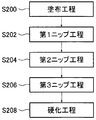
- FIG. 1 is a flowchart showing an example of an embodiment of a laminating method of the present invention
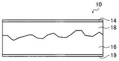
- FIG. 2 is a cross-sectional view conceptually showing a laminate produced by the manufacturing method shown in FIG. 1, and
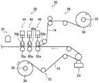
- FIG. It is a figure which shows notionally an example of the laminating apparatus which enforces the manufacturing method shown in FIG.
- an application step S200 for applying an adhesive onto a substrate 16 conveyed by a predetermined conveyance path, and conveyance by a predetermined conveyance path with the substrate 16 coated with the adhesive A first nip step S202 that sandwiches and presses (nips) and bonds the support 14 to be bonded, a second nip step S204 that presses the bonded substrate 16 and the support 14 further, and a third nip step S206,
- the curing step S208 for curing the adhesive is sequentially performed.
- the laminate obtained by the production method of the present invention is laminated on the substrate 16 having irregularities on the surface, the adhesive layer 18 laminated on the substrate 16, and the adhesive layer 18.
- the support 14 is formed, and the unevenness on the surface of the substrate 16 is embedded with an adhesive layer 18 to have a smooth surface.
- the laminate 10 will be described in detail later.
- the laminating apparatus 20 includes a substrate transport unit 22 that transports the substrate 16, an adhesive application unit 24 that performs the coating step S ⁇ b> 200, a support transport unit 26 that transports the support 14,
- the first nip portion 40 that performs the first nip step S202, the second nip portion 42 that performs the second nip step S204, and the nip portion 28 that includes the third nip portion 44 that performs the third nip step S206, and the curing step S208 are performed.
- a light irradiation unit 30 is performed.
- the substrate 16 used in the present invention is not particularly limited as long as it is a non-metallic substrate, but is preferably a substrate made of a rubber sheet or a resin sheet. Since the present invention is more effective for a substrate having a variation in film thickness, it is more suitable when a rubber sheet having a variable film thickness is used as the substrate.
- the rubber sheet manufactured by the various well-known methods can be utilized. That is, the rubber sheet can be produced by a known method such as compression molding, transfer molding, injection molding, extrusion molding, or centrifugal molding. Specifically, it is described in Journal of Japan Rubber Association vol.68 (1995) p76-85, p108-118, vol.69 (1996) p375-383. In addition, materials described in “Rubber / Plastic Compounding Chemicals Revised 2nd Edition” (Rubber Digest Co., Ltd.) can be used.
- this invention can be utilized more suitably with respect to the rubber sheet which is thick and has a large surface unevenness, for example, a rubber sheet used as a printing plate precursor. Alternatively, it can be suitably used for a precision printing blanket, an intermediate transfer body for OA equipment, and the like.
- substrate 16 can be utilized suitably. In the substrate manufactured by such a manufacturing method, the contact surface with the conveyor is formed smoothly, but the upper surface is greatly uneven due to casting unevenness and drying air.
- the present invention can be suitably embedded in such a rubber sheet because even large irregularities can be suitably embedded.
- the present invention can be suitably applied to the substrate 16 having a thickness in the range of 400 ⁇ m to 6000 ⁇ m. Further, the present invention, the elastic modulus, can be suitably applied by a rubber sheet is 0.5N / mm 2 ⁇ 5.0N / mm 2.
- a numerical range represented by using “to” means a range including numerical values described before and after “to” as a lower limit value and an upper limit value.
- the resin sheet used in the present invention is not particularly limited, and examples thereof include silicone resins, fluorine resins, PET films, PP films, and the like.
- the substrate 16 resin sheets manufactured by various known methods can be used.
- the resin sheet can be produced by a known method described in Patent Documents 3 to 5.
- substrate 16 is not limited to what consists of one layer, The sheet
- the substrate transport unit 22 transports the long substrate 16 unwound from the substrate roll 34 in the longitudinal direction of the substrate 16 through a predetermined transport path.
- the substrate transport unit 22 includes a rotating shaft 32 on which the substrate roll 34 is mounted, and a plurality of guide rollers that guide the substrate 16 along a predetermined transport path.
- the substrate 16 When the substrate roll 34 is mounted on the rotating shaft 32, the substrate 16 is guided by a plurality of guide rollers and passed through a predetermined path that sequentially passes through the adhesive application unit 24, the nip unit 28, and the light irradiation unit 30. (Inserted).
- the substrate 16 is conveyed along a predetermined path by a conveying means such as a driving roller (not shown).
- the adhesive application part 24, the nip part 28, and the light irradiation part 30 are sequentially arranged on the transport path of the substrate 16 from the upstream side.
- the substrate 16 is sent out from the substrate roll 34, and the long substrate 16 is transported in the longitudinal direction along a predetermined transport path, and is supported on the substrate 16 by each unit disposed on the transport path of the substrate 16. Laminate the body.
- the substrate 16 is preferably transported at a constant speed with the speed controlled by transport means such as a driving roller.
- the adhesive application part 24 is a part which performs application
- the adhesive application unit 24 preferably applies the adhesive by a gravure application method. By applying the adhesive by a gravure coating method, the adhesive can be applied more uniformly, that is, so that the surface of the adhesive becomes smooth. In particular, the adhesive can be uniformly applied in the width direction of the substrate 16.
- Examples of the coating machine that performs the gravure coating method include a direct gravure coater, a chamber doctor coater, an offset gravure coater, a kiss coater using a gravure roll, and a reverse roll coater composed of a plurality of rolls.
- a cylindrical blade there are a die coater that supplies adhesive directly to the application part by applying adhesive to the application part and scraping off with the blade, applying a slot die, etc., and a liquid reservoir
- the coating means may be determined in consideration of conditions such as the type of support, the coating amount, and the coating speed among various coating machines such as a knife coater that is made and applied while scraping off excess liquid with a knife.
- a photocurable adhesive agent a thermosetting adhesive agent, an anaerobic adhesive agent etc. are illustrated.
- a photocurable adhesive is preferable from the viewpoint of easy control of the curing reaction, and an ultraviolet curable adhesive is preferable as the photocurable adhesive.
- the adhesive include I.I. Those described in the edition of Skeist, “Handbook of Adhesives”, the second edition (1977) can be used.
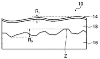
- FIG. 4 is a cross-sectional view conceptually showing the laminate in a state before an adhesive is applied to the main surface of the substrate 16 and the support 14 is attached.
- the surface of the adhesive layer 18 applied to the substrate 16 preferably has a maximum height Rmax of a surface roughness index of 200 ⁇ m or less.
- the maximum height Rmax is the maximum height Rz defined in JIS B0601: 2001.
- Rmax (adhesive layer 18 and substrate 16).
- Rmax is obtained by measuring the aforementioned (maximum film thickness)-(minimum film thickness) with a non-contact displacement meter such as a laser displacement meter or an ultrasonic displacement meter.
- the viscosity of the adhesive is preferably 0.001 Pa ⁇ s to 100 Pa ⁇ s, more preferably 0.01 Pa ⁇ s to 10 Pa ⁇ s, and still more preferably 0.05 Pa ⁇ s to 5 Pa ⁇ s. It is.
- the height Rmax can be 200 ⁇ m or less.
- the surface can be smoothed when nip is performed at the nip portion 28 described later, and the film thickness accuracy can be improved.
- a viscosity is measured with well-known viscometers, such as a capillary viscometer, a falling ball viscometer, a rotational viscometer, a vibration viscometer, a parallel plate viscometer, a bubble viscometer.
- a viscometer such as a capillary viscometer, a falling ball viscometer, a rotational viscometer, a vibration viscometer, a parallel plate viscometer, a bubble viscometer.
- the adhesive When a photocurable adhesive is used as the adhesive, the adhesive may be liquid or solid at room temperature (25 ° C.). When it is liquid at room temperature, the viscosity at 25 ° C. is preferably in the above range.
- the adhesive When the adhesive is solid at room temperature, it is preferable to heat to a temperature at which the photocurable adhesive softens. That is, it is preferable to heat to a temperature at which the viscosity is in the above range.
- the solvent may be removed by drying after coating using an adhesive dissolved in a solvent.
- a solventless hot melt photocurable adhesive may be applied in a heated state.
- the thickness of the adhesive layer 18 applied to the substrate 16 before the support 14 is attached is the thickness of the substrate 16, the size of the irregularities on the surface of the substrate 16, the film thickness accuracy required for the laminate 10, etc.
- the thickness may be appropriately determined depending on the thickness, but is preferably 50 ⁇ m to 300 ⁇ m.
- By setting the thickness of the adhesive layer 18 to 50 ⁇ m or more it is more preferable to embed irregularities on the main surface of the substrate 16 and smooth the surface while ensuring adhesive strength while suppressing loss of the adhesive. be able to.
- the thickness of the adhesive layer 18 to 300 ⁇ m or less it is possible to smooth the surface while suppressing distortion due to curing shrinkage during curing of the adhesive.
- the substrate 16 to which the adhesive is applied is supplied to the first nip portion of the nip portion 28.
- the support transport unit 26 transports the long support 14 unwound from the support roll 38 in the longitudinal direction of the support 14 along a predetermined transport path.
- the support transport unit 26 includes a rotating shaft 36 on which the support roll 38 is mounted, and a plurality of guide rollers that guide the support 14 along a predetermined transport path.
- the support 14 When the support roll 38 is mounted on the rotary shaft 36, the support 14 is guided by a plurality of guide rollers and passed through a predetermined path passing through the nip portion 28.
- the support 14 is conveyed along a predetermined path by a conveying means such as a driving roller (not shown).
- the support 14 is supplied to the first nip portion 40 of the nip portion 28.
- the support 14 is not particularly limited, but those having high dimensional stability are preferably used.
- metals such as steel, stainless steel, and aluminum, thermoplastic resins (eg, cycloolefin resins, crystalline polyolefin resins, polyester resins, polycarbonate resins, acrylic resins, triacetyl cellulose resins), styrene-butadiene rubber And synthetic resins such as plastic resins and plastic resins reinforced with glass fibers (such as epoxy resins and phenol resins).
- a PET (polyethylene terephthalate) film or a steel substrate is more preferably used.
- the support 14 is preferably transparent and more preferably a PET film. If the support is transparent, when a photocurable adhesive is used as the adhesive, light can be irradiated from the support 14 side, and the curing reaction can be performed with a small dose.
- the thickness of the support 14 is preferably 50 ⁇ m to 350 ⁇ m, and more preferably 75 ⁇ m to 250 ⁇ m.
- the nip portion 28 is a portion that sandwiches and presses (ie, nips) and bonds the substrate 16 and the support 14 that are respectively transported along a predetermined transport path and corrects the film thickness accuracy of the stacked body 10. is there.
- the nip portion 28 includes a first nip portion 40 that performs the first nip step S202, a second nip portion 42 that performs the second nip step, and a third nip portion 44 that performs the third nip step.
- the first nip portion 40, the second nip portion 42, and the third nip portion 44 have basically the same configuration except that the intervals between the nip rollers (nip interval) are different from each other.
- the nip portion 40 will be described. Only the differences between the second nip portion 42 and the third nip portion 44 will be described.
- FIG. 5 is a diagram conceptually showing the configuration of the first nip portion 40.
- the first nip portion 40 has a mechanism capable of adjusting the nip interval.
- the first nip portion 40 includes a pair of nip rollers 50 including a lower nip roller 50a and an upper nip roller 50b, wedge-shaped stoppers 52a and 52b, adjustment screws 54a and 54b, a guide rail 56, and the like. And a bearing portion 57 and an air cylinder 58.
- the lower nip roller 50a and the upper nip roller 50b rotate around a direction orthogonal to the conveyance direction of the substrate 16 as an axis.
- the lower nip roller 50a is rotatably held at a predetermined position.
- the upper nip roller 50 b disposed above the lower nip roller is rotatably held by the bearing portion 57.
- the bearing portion 57 has a slit on the side surface, and is guided in the vertical direction by a guide rail 56 fitted into the slit.
- a pair of wedge-shaped stoppers 52a and 52b are arranged on the lower surface of the bearing portion 57 so as to overlap in the vertical direction.
- the wedge-shaped stoppers 52a and 52b are configured such that the height of the wedge-shaped stopper 52b can be adjusted by changing the horizontal position by adjusting screws 54a and 54b, respectively.
- the upper surface of the bearing portion 57 is pressed downward by the air cylinder 58. Accordingly, the bearing portion 57 is held with its lower surface in contact with the upper surface of the wedge-shaped stopper 52b.
- the first nip portion 40 adjusts the height of the bearing portion 57, that is, the upper nip roller 50b, by adjusting the height of the wedge-shaped stopper 52b with the adjusting screws 54a and 54b.
- the gap (nip interval) between the nip roller 50b and the lower nip roller 50a can be adjusted.
- the first nip portion 40, the second nip portion 42, and the third nip portion 44 are adjusted to have different nip intervals by such a nip interval adjusting mechanism.
- the nip interval is set to be narrower (or equivalently) toward the downstream side in the conveyance direction of the substrate 16. That is, the nip interval of the first nip portion 40 is set to be the largest, and the nip interval of the third nip portion 44 is set to be the smallest.
- the pair of nip rollers 50 of the first nip portion 40 continuously bonds (laminates) the substrate 16 with the adhesive and the support 14 that pass between them. At that time, the adhesive is weighed according to the nip interval to define the laminate thickness.
- the nip roller pair 60 including the lower nip roller pair 60a and the upper nip roller 60b in the second nip portion 42 further nips the laminate of the substrate 16, the adhesive, and the support 14 that has passed through the first nip portion 40. Then, the adhesive is weighed by a nip interval smaller than the first nip portion 40 to define the laminate thickness.
- the nip roller pair 70 including the lower nip roller 70a and the upper nip roller 70b of the third nip portion 44 is a laminate of the substrate 16, the adhesive, and the support 14 that has passed through the first nip portion 40 and the second nip portion 42.
- the substrate 16 when a rubber sheet or a resin sheet is used as the substrate 16 and the support 14 is laminated by applying an adhesive on the substrate 16, a plurality of nip roller pairs whose nip interval becomes narrower in the later stage, After sequential nips, the adhesive is cured. Thereby, the unevenness on the surface of the substrate 16 is embedded, and the smoothness on the surface of the support 14 is improved by smoothing the adhesive by a plurality of nips, thereby improving the film thickness accuracy of the laminate 10. be able to.
- the substrate 16 is moved when passing through the nip roller pair due to the elasticity of the substrate 16 or the viscosity (liquid resistance) of the adhesive. It deforms and the substantial nip interval changes. For this reason, the adhesive cannot be sufficiently smoothed, and the smoothness of the support surface cannot be improved to sufficiently improve the film thickness accuracy.
- the present invention nips a plurality of times with a plurality of pairs of nip rollers, it is possible to gradually smooth the adhesive and improve the smoothness of the surface of the support 14 and improve the film thickness accuracy. be able to.
- the substrate 16 is an elastic body such as a rubber sheet
- the substrate 16 is easily deformed when passing between the pair of nip rollers. Therefore, the adhesive cannot be sufficiently smoothed with one nip.
- the present invention since the nip is performed a plurality of times, the adhesive can be sufficiently applied even when the substrate 16 is an elastic body such as a rubber sheet. Therefore, the present invention is particularly preferably used when a rubber sheet is used as the substrate.
- the material of the nip rollers 50a and 50b is not particularly limited, but a combination of a metal roll and a metal roll is preferable. Depending on the characteristics of the substrate 16 or the like, a metal roll and a rubber roll, or a combination of a rubber roll and a rubber roll may be used.
- the upper nip roller 50b which is a roller on the support 14 side, preferably has a heating mechanism.
- the nip roller 50b has a heating mechanism, and when the nip is performed, the temperature of the adhesive is raised to lower the viscosity, thereby reducing the liquid resistance when passing between the nip rollers, preventing the deformation of the substrate 16, and the support 14 Surface smoothness can be improved.
- the adhesive passes between the nip rollers for a moment, when heated by the heating means, the temperature of the surface of the adhesive increases and the viscosity of the surface portion of the adhesive decreases. Therefore, the surface of the adhesive becomes easier to level, and the smoothness of the surface of the support 14 can be improved.
- all the nip roller pairs may have heating means, but it is preferable that at least the upper nip roller 70b of the nip roller pair in the final stage has heating means. Since the final stage upper nip roller 70b has a heating means, the final film thickness accuracy of the laminate 10 can be preferably improved.
- the heating temperature by the heating means is not particularly limited, and is appropriately determined according to the characteristics of the adhesive, the operating conditions such as the material and roll diameter of the substrate 16 and the support 14, the conveyance speed, and the required film thickness accuracy. do it.
- As the heating means of the upper nip roller 50b various known heating means such as an electric heater and a liquid jacket described in JP-A-6-315980 can be used.
- the roll diameters of the nip rollers 50a and 50b are preferably small in terms of manufacturing cost, but if the diameter is reduced, the rollers may be bent due to liquid resistance.
- the heating means is provided, the heat transfer area is reduced by reducing the diameter, so that the adhesive cannot be sufficiently heated to reduce the liquid resistance, which may cause bending.
- the roll diameters of the nip rollers 50a and 50b may be appropriately determined in consideration of the above points.
- the viscosity range of the adhesive is 0.05 Pa ⁇ s to 5 Pa ⁇ s and the nip roller 50b has a heating mechanism
- the nip intervals of the first nip portion 40, the second nip portion 42, and the third nip portion 44 are the characteristics of the adhesive, the material and elastic modulus of the substrate 16 and the support 14, the roll diameter, and the presence or absence of heating means. It may be determined as appropriate according to the operating conditions such as the conveyance speed and the required film thickness accuracy.
- the mechanism for adjusting the nip interval is not limited to the configuration in the illustrated example, and various known mechanisms for adjusting the nip interval can be used.
- the mechanism has a mechanism for adjusting the nip interval.
- the present invention is not limited to this, and does not have the mechanism for adjusting the nip interval.
- the portion 42 and the third nip portion 44 may be fixed at predetermined nip intervals.
- the nip portion 28 has three nip roller pairs, but the present invention is not limited to this, and may have two nip roller pairs, or The configuration may include four or more pairs of nip rollers. Considering the effect of improving the film thickness accuracy and cost, it is preferable to have 2 to 5 nip roller pairs.
- the substrate 16 that has passed through the nip portion 28 is supplied to the light irradiation unit 30.
- the light irradiation unit 30 performs the curing step S208.
- the light irradiation unit 30 irradiates light such as ultraviolet rays (UV light) to cure the adhesive (adhesive layer 18) between the substrate 16 and the support 14. It is something to be made.
- the laminated body 10 is obtained by irradiating light such as ultraviolet rays to cure the adhesive and bonding the substrate 16 and the support 14.
- the light used in the curing step S208 is not particularly limited as long as it is an actinic ray that can cure the photocurable adhesive by irradiation, and is widely ⁇ -ray, ⁇ -ray, X-ray, ultraviolet (UV), visible. It includes light rays, electron beams, laser light, and the like. Among these, it is particularly preferable to use ultraviolet rays.
- Laser light is light with high coherence and is excellent in directivity and convergence, and examples thereof include an infrared laser described later.
- the light irradiated in the curing step S208 is preferably 200 to 600 nm. Although there is no restriction
- At least one of the support 14 and the substrate 16 is preferably transparent, and more preferably the support 14 is transparent.
- the peeling force between the substrate 16 and the support 14 after curing the adhesive layer 18 is preferably 2 N / cm or more, more preferably 3 N / cm or more, and 4 N / cm or more. Is more preferable. Moreover, it is preferable that it is 20 N / cm or less.
- the laminate 10 that has passed through the light irradiation means is subjected to the next step.
- the laminate 10 may be wound up, or may be used for a process of attaching a cover film 19 described later.
- the substrate 16 is pulled out from the substrate roll 34 and inserted through a predetermined transport path.
- the substrate 16 is driven by a driving source (not shown) and starts transporting the substrate 16.
- a support roll 38 is loaded on the rotary shaft 36, and the support 14 is pulled out from the support roll 38 and inserted through a predetermined transport path.
- the support body 14 is driven by a drive source (not shown) and starts transporting the support body 14 in synchronization with transport of the substrate 16.
- a photocurable adhesive is applied to the main surface of the substrate 16 by the adhesive application unit 24 as an application step S200.
- the first nip portion 40 bonds the support 14 to the substrate 16 on which the adhesive is applied.
- the second nip step S204 the second nip portion 42 nips the laminate of the substrate 16, the adhesive, and the support 14, measures the adhesive, and defines the laminate thickness.
- the third nip step S206 the third nip portion 44 nips the laminate of the substrate 16, the adhesive and the support 14, measures the adhesive, and defines the laminate thickness.
- the light irradiation unit 30 irradiates the adhesive with UV light or the like, cures the adhesive, bonds the substrate 16 and the support 14, and the substrate 16, the adhesive layer 18 and The laminate 10 in which the support 14 is laminated is produced.
- FIG. 6 is a diagram highlighting the unevenness of the surface of the laminated body 10 shown in FIG. 2 on the support 14 side.
- the laminated body 10 is formed by laminating a substrate 16 having irregularities on the main surface, an adhesive layer 18 laminated on the substrate 16, and a support 14 laminated on the adhesive layer 18. It is made. That is, the laminate 10 has the surface of the laminate 10 (the surface of the support 14) embedded by bonding the substrate 16 and the support 14 with an adhesive to embed the irregularities of the substrate 16 with the adhesive layer 18. The film thickness accuracy of the laminate 10 is improved.
- the interface z between the substrate 16 of the laminate 10 and the adhesive layer 18, and the maximum height of surface roughness index and R 0, the ratio R 0 / d 0 between the average thickness d 0 of the substrate 16 Is preferably 5% to 30%.
- the average thickness d 0 of the substrate 16 of the laminate 10 is preferably 400 ⁇ m to 6000 ⁇ m.
- the material of the substrate 16 is preferably rubber, preferably, elastic modulus is 0.5N / mm 2 ⁇ 5.0N / mm 2.
- the average thickness d 1 of the adhesive layer 18 of the laminate 10 is preferably 50 ⁇ m to 300 ⁇ m.
- the average thickness d 1 of the adhesive layer 18 satisfies the above range, the unevenness of the substrate 16 can be embedded more suitably, and the film thickness accuracy can be improved.
- the laminated body 10 produced by the laminating method of the present invention has the maximum height R 1 and the thickness d of the laminated body 10 when the maximum height of the surface roughness index on the surface of the support 14 is R 1.
- the ratio R 1 / d can be 0.5% to 2.5%.
- the substrate 16 side may be laminated on the surface.
- a film similar to the support 14 can be used.
- a PET (polyethylene terephthalate) film is particularly preferable from the viewpoints of handleability and cost.
- the cover film 19 can be laminated simultaneously or sequentially with the support 14 by a method similar to the method for laminating the support 14 described above.
- the thickness of the cover film 19 is preferably 25 ⁇ m or more and more preferably 50 ⁇ m or more from the viewpoint of preventing scratches and dents. On the other hand, from a viewpoint of cost, 500 micrometers or less are preferable and 200 micrometers or less are more preferable.
- the surface of the cover film 19 may be plain or may be matted.
- the cover film 19 must be peelable. When the cover film 19 cannot be peeled or is difficult, or when the substrate 16 and the cover film 19 are weakly bonded and easily peeled off, a slip coat layer may be provided between both layers.
- the material used for the slip coat layer is a resin that is soluble or dispersible in water, such as polyvinyl alcohol, polyvinyl acetate, partially saponified polyvinyl alcohol, hydroxyalkyl cellulose, alkyl cellulose, polyamide resin, and less adhesive. It is preferable to use it as a main component.
- Example 1 As Example 1, the laminated body 10 was produced using the laminating apparatus 20 shown in FIG. Here, the thickness d 0 of the substrate 16 and the maximum height R 0 of the surface of the substrate 16 were measured by scanning the surface with a laser displacement meter before applying the adhesive. The maximum height Rmax when the adhesive was applied was measured by scanning the surface with a laser displacement meter after the adhesive was applied. Further, the thickness d and the surface roughness R1 of the laminate 10 were measured by scanning the surface with a laser displacement meter after lamination. The laser displacement meter uses LK-H008 manufactured by Keyence Corporation, and is arranged in three rows each in the width direction on each pass roll (not shown) before coating, after coating, and after lamination. And the web center was measured 100m continuously online.
- Substrate 16 the hardness 64 ° (Shore A), the average thickness d 0 is used 1.5mm rubber sheet (manufactured by Tigers Polymer Corporation TAKL6503).
- the maximum height R 0 of the surface of the substrate 16 was 200 ⁇ m. That is, the ratio R 0 / d 0 between the thickness d 0 and the maximum height R 0 of the substrate 16 before lamination was 13%.
- an adhesive an ultraviolet curable adhesive (TB3042B) manufactured by ThreeBond Co., Ltd. was used as an adhesive. The viscosity of the adhesive was 0.5 Pa ⁇ s (25 ° C.). Further, the adhesive was coated so that the adhesive thickness was 120 ⁇ m and the maximum height Rmax was 60 ⁇ m.
- the support 14 was a PET film having a thickness of 0.1 mm.
- the nip rollers were all made of SUS304 and the roll diameter was 300 mm. Further, the nip interval of the first nip portion 40 was 60 ⁇ m, the nip interval of the second nip portion 42 was 30 ⁇ m, and the nip interval of the third nip portion 44 was 10 ⁇ m.
- the upper nip roller 70b was heated to 50 ° C. by a heating means.
- the light irradiation part 30 shall irradiate UV light.
- the exposure amount was 1200 mJ / cm 2 .
- the thickness d of the obtained laminate 10 and the maximum height of the surface roughness index on the surface on the support 14 side are obtained.
- R 1 was measured.
- the thickness d was 1.7 mm
- the maximum height R 1 was 34 ⁇ m. That is, the ratio R 1 / d between the thickness d and the maximum height R 1 was 2%.
- Example 1 In the same manner as in Example 1, except that the number of nip roller pairs in the nip part is one pair, and the adhesive is applied to the substrate 16 by dropping an adhesive instead of the adhesive application part 24. A laminate was produced. The thickness d of the produced laminate was 1.7 mm, and the maximum height R 1 was 85 ⁇ m. That is, the ratio R 1 / d was 5%.
- Example 1 which is an example of the present invention, can correct film thickness variation and improve film thickness accuracy as compared with Comparative Example 1. From the above results, the effect of the present invention is clear.
Landscapes
- Engineering & Computer Science (AREA)
- Mechanical Engineering (AREA)
- Physics & Mathematics (AREA)
- Fluid Mechanics (AREA)
- Lining Or Joining Of Plastics Or The Like (AREA)
- Laminated Bodies (AREA)
- Chemical & Material Sciences (AREA)
- Chemical Kinetics & Catalysis (AREA)
- General Chemical & Material Sciences (AREA)
Abstract
Description
また、少なくとも最下流のニップローラ対の一方のニップローラは、加熱手段を有するのが好ましい。
また、貼付工程の直前における、非金属基板の一方の主面に塗布された接着剤の平均厚さが50μm~300μmであるのが好ましい。
また、非金属基板の弾性率が、0.5N/mm2~5.0N/mm2であるのが好ましい。
また、2対以上のニップローラ対は、それぞれ、ニップ間隔を調整する機構を有することが好ましい。
また、非金属基板の他方の主面にカバーフィルムが接着されているのが好ましい。
また、基板16として、キャスティングコンベア上に塗設して成形する製造方法で製造される基板が好適に利用可能である。このような製造方法で製造される基板は、コンベアとの接触面は平滑に形成されるものの、上面は流延ムラや乾燥風の影響で大きな凹凸ができてしまう。本発明は、大きな凹凸であっても好適に包埋できるため、このようなゴムシートに、より好適に適用できる。
また、本発明は、弾性率が、0.5N/mm2~5.0N/mm2であるゴムシートにより好適に適用できる。
なお、本明細書において「~」を用いて表される数値範囲は、「~」の前後に記載される数値を下限値および上限値として含む範囲を意味する。
また、基板16は、1層からなるものに限定はされず、複数の膜を積層したシートであってもよい。
基板搬送部22は、基板ロール34を装着する回転軸32と、基板16を所定の搬送経路で案内する複数のガイドローラとを有する。
なお、基板16は、駆動用ローラ等の搬送手段によって、速度制御され、一定速度で搬送されることが好ましい。
接着剤塗布部24は、塗布工程S200を行う部位である。具体的には、接着剤塗布部24は、基板16の主面(支持体14側の面)に所定の厚さの接着剤を塗布する。
ここで、接着剤塗布部24は、グラビア塗布方式で接着剤を塗布することが好ましい。グラビア塗布方式で接着剤を塗布することにより、接着剤をより均一に、すなわち、接着剤の表面が平滑になるように塗布することができる。特に、基板16の幅方向において、接着剤を均一に塗布することができる。
接着剤としては、例えば、I.Skeist編、「Handbook of Adhesives」、第2版(1977)に記載のものを用いることができる。
支持体14を貼り付ける前の積層体において、基板16に塗布された接着剤層18の表面は、表面粗さ指標の最大高さRmaxが200μm以下であることが好ましい。接着剤層18の表面の最大高さRmaxを200μm以下とすることにより、後述するニップ部28で支持体14を貼り付けた際に、表面を平滑化でき、膜厚精度を向上することができる。
ここで、本願において、最大高さRmaxとは、JIS B0601:2001にて、規定される最大高さRzである。なお、本実施例においては、基板16の他方の主面(接着剤層18とは反対側の面)は、実質的に平滑であると考えて、Rmax=(接着剤層18と基板16との積層体の最大膜厚)-(接着剤層18と基板16との積層体の最小膜厚)と定義する。
具体的には、レーザー変位計や超音波変位計等の非接触式変位計で前述の(最大膜厚)-(最小膜厚)を測定してRmaxを求める。
ここで、本願において、粘度は、毛細管粘度計、落下球粘度計、回転粘度計、振動粘度計、平行平板粘度計、気泡粘度計等公知の粘度計で測定する。
また、接着剤を溶剤に溶解させたものを使用して塗布後、溶剤を乾燥除去させてもよい。あるいは、無溶剤型のホットメルト光硬化性接着剤を加熱した状態で塗布してもよい。
接着剤層18の厚さを50μm以上とすることにより、より好適に、接着剤のロスを抑制しながら接着強度を確保しつつ、基板16主面の凹凸を包埋し、表面を平滑にすることができる。また、接着剤層18の厚さを300μm以下とすることにより、接着剤硬化時の硬化収縮に起因する歪を抑えつつ、表面を平滑にすることができる。
接着剤が塗布された基板16は、ニップ部28の第1ニップ部に供給される。
支持体搬送部26は、支持体ロール38を装着する回転軸36と、支持体14を所定の搬送経路で案内する複数のガイドローラとを有する。
支持体14は、ニップ部28の第1ニップ部40に供給される。
支持体が透明であれば、接着剤として光硬化性接着剤を使用する場合に、支持体14側から光を照射することができ、少ない照射量で硬化反応を行うことができる。
また、支持体14の厚さは、50μm~350μmとするのが好ましく、75μm~250μmとするのがさらに好ましい。
ニップ部28は、それぞれ所定の搬送経路で搬送された基板16と支持体14とを挟み込んで押圧し(すなわち、ニップして)、貼り合せると共に、積層体10の膜厚精度を補正する部位である。ニップ部28は、第1ニップ工程S202を行う第1ニップ部40と、第2ニップ工程を行う第2ニップ部42と、第3ニップ工程を行う第3ニップ部44とを有する。
ここで、第1ニップ部40は、ニップ間隔を調整可能な機構を有する。
図5に示すように、第1ニップ部40は、下ニップローラ50aと上ニップローラ50bからなる1対のニップローラ対50と、くさび型ストッパ52a、52bと、調整ネジ54a、54bと、ガイドレール56と、軸受部57と、エアシリンダ58とを有する。
具体的には、基板16の搬送方向の下流側ほど、ニップ間隔が狭くなる(もしくは同等に)ように設定される。すなわち、第1ニップ部40のニップ間隔が最も大きく、第3ニップ部44のニップ間隔が最も小さく設定される。
しかしながら、精度が不十分であったり、製造方法を実施するための設備上の制約があり汎用性が無かったり、装置に特殊加工が必要となりコストが増加するという問題があった。
上ニップローラ50bの加熱手段としては、例えば、特開平6-315980号に記載の電気ヒーター、液体ジャケット等、種々の公知の加熱手段を利用することができる。
また、図示例においては、ニップ間隔を調整する機構を有する構成としたが、本発明はこれに限定はされず、ニップ間隔を調整する機構を有さず、第1ニップ部40、第2ニップ部42、第3ニップ部44が、それぞれ所定のニップ間隔に固定されていてもよい。
ニップ部28通過した基板16は、光照射部30に供給される。
光照射部30は、硬化工程S208を行うものであり、例えば、紫外線(UV光)等の光を照射して、基板16と支持体14との間の接着剤(接着剤層18)を硬化させるものである。紫外線等の光を照射して接着剤を硬化させて、基板16と支持体14とを接着することにより、積層体10を得る。
なお、レーザー光とは、コヒーレンスの高い光であり、指向性や収束性に優れ、例えば、後述する赤外線レーザーなどが例示できる。
また、硬化工程における光の露光量は、光硬化性接着剤が硬化する量であればよいが、10~4,000mJ/cm2であることが好ましく、20~2,500mJ/cm2であることがより好ましい。
接着剤層18硬化後の、基板16と支持体14との間の剥離力は、2N/cm以上であることが好ましく、3N/cm以上であることがより好ましく、4N/cm以上であることが更に好ましい。また、20N/cm以下であることが好ましい。
前述のように、回転軸32に基板ロール34が装填されると、基板ロール34から基板16が引き出され、所定の搬送経路を挿通される。基板16が所定の搬送経路に挿通されると、図示しない駆動源により駆動され基板16の搬送を開始する。
一方、回転軸36には支持体ロール38が装填され、支持体ロール38から支持体14が引き出され、所定の搬送経路を挿通される。支持体14が所定の搬送経路に挿通されると、図示しない駆動源より駆動され、基板の16の搬送と同期して、支持体14の搬送を開始する。
図6は、図2に示す積層体10の支持体14側の面の表面の凹凸を強調して示した図である。
また、積層体10の基板16の平均厚さd0は、好ましくは、400μm~6000μmである。
また、基板16の材質は、好ましくはゴムであり、好ましくは、弾性率が0.5N/mm2~5.0N/mm2である。
表面粗さR0および厚さd0が上記範囲を満たす基板16に対して、本発明のラミネート方法を適用することにより、好適に基板16の凹凸を包埋して、膜厚精度を向上させることができる。特に、材質がゴムで弾性率が上記範囲を満たす基板16は、ニップの際に変形してしまうため、膜厚精度を向上させることが難しいが、本発明を適用することにより、好適に膜厚精度を向上させることができる。
接着剤層18の平均厚さd1が上記範囲を満たすことにより、より好適に基板16の凹凸を包埋して、膜厚精度を向上させることができる。
カバーフィルム19としては、支持体14と同様のフィルムを使用することができる。なお、取り扱い性、コストの観点からPET(ポリエチレンテレフタレート)フィルムが特に好ましい。カバーフィルム19は、上述した支持体14のラミネート方法と同様な方法により、支持体14と同時または逐次にラミネートすることができる。
またカバーフィルム19の表面はプレーンでもよいし、マット化処理されていてもよい。
また、カバーフィルム19を設ける場合、カバーフィルム19は剥離可能でなければならない。カバーフィルム19が剥離不可能もしくは困難な場合や、逆に基板16とカバーフィルム19の接着が弱く剥がれやすい場合には、両層間にスリップコート層を設けてもよい。
また、スリップコート層に使用される材料は、ポリビニルアルコール、ポリ酢酸ビニル、部分鹸化ポリビニルアルコール、ヒドロシキアルキルセルロース、アルキルセルロース、ポリアミド樹脂など、水に溶解又は分散可能で、粘着性の少ない樹脂を主成分とすることが好ましい。
実施例1として、図3に示すラミネート装置20を用いて積層体10を作製した。
ここで、基板16の厚さd0、および、基板16表面の最大高さR0は接着剤塗工前にレーザー変位計にて表面を走査して計測した。また、接着剤塗布時の最大高さRmaxは接着剤の塗工後にレーザー変位計にて表面を走査して計測した。また、積層体10の厚さd、表面粗さR1はラミネート後にそれぞれレーザー変位計にて表面を走査して計測した。レーザー変位計は株式会社キーエンス製LK―H008を用い、塗工前、塗工後、ラミネート後の各パスロール(図示せず)上に幅方向に各3列ずつ配置し、エッジより50mm内側の位置とウエブセンターをオンラインで連続的に100m計測した。
また、接着剤として、株式会社スリーボンド製の紫外線硬化型接着剤(TB3042B)を用いた。接着剤の粘度は、0.5Pa・s(25℃)であった。また、塗布時の接着剤厚さは120μm、最大高さRmaxは、60μmとなるように塗布した。
また、支持体14は、厚さ0.1mmのPETフィルムを用いた。
また、第1ニップ部40のニップ間隔は、60μmとし、第2ニップ部42のニップ間隔は、30μmとし、第3ニップ部44のニップ間隔は、10μmとした。
また、上ニップローラ70bは加熱手段により、50℃に加熱した。
ニップ部のニップローラ対の数を1対とし、また、接着剤塗布部24に代えて接着剤を滴下して基板16に接着剤を付与する構成とした以外は、実施例1と同様にして、積層体の作製を行った。作製した積層体の厚さdは、1.7mmで、最大高さR1は、85μmであった。すなわち、比R1/dは5%であった。
以上の結果から、本発明の効果は、明らかである。
14 支持体
16 基板
18 接着剤層
19 カバーフィルム
20 ラミネート装置
22 基板搬送部
24 接着剤塗布部
26 支持体搬送部
28 ニップ部
30 光照射部
32、36 回転軸
34 基板ロール
38 支持体ロール
40 第1ニップ部
42 第2ニップ部
44 第3ニップ部
50a、60a、70a 下ニップローラ
50b、60b、70b 上ニップローラ
52a、52b くさび型ストッパ
54a、54b 調整ネジ
56 ガイドレール
57 軸受部
58 エアシリンダ
z 界面
Claims (13)
- 非金属基板に、支持体を貼り合せるラミネート方法であって、
前記非金属基板の一方の主面に接着剤を塗布する塗布工程と、
前記非金属基板と前記支持体とを所定の搬送経路で搬送して、前記支持体を前記非金属基板の前記一方の主面に貼り付ける貼付工程と、
前記貼付工程の後に、前記接着剤を硬化させる硬化工程とを有し、
前記貼付工程は、2対以上のニップローラ対の間を順次、通過させて前記非金属基板と前記支持体とを貼り付けるものであり、前記2対以上のニップローラ対は、下流に配置されるニップローラ対のニップ間隔が、上流に配置されるニップローラ対のニップ間隔以下に設定されていることを特徴とするラミネート方法。 - 前記貼付工程の直前における、前記非金属基板の前記一方の主面に塗布された前記接着剤の表面は、表面粗さ指標の最大高さRmaxが200μm以下である請求項1に記載のラミネート方法。
- 少なくとも最下流のニップローラ対の一方のニップローラは、加熱手段を有することを特徴とする請求項1または2に記載のラミネート方法。
- 前記2対以上のニップローラ対の各ニップローラの径は、150mm~500mmである請求項1~3のいずれか1項に記載のラミネート方法。
- 前記貼付工程の直前における、前記非金属基板の前記一方の主面に塗布された前記接着剤の平均厚さが50μm~300μmである請求項1~4のいずれか1項に記載のラミネート方法。
- 前記貼付工程の直前における、前記接着剤の粘度が、0.001Pa・s~100Pa・sである請求項1~5のいずれか1項に記載のラミネート方法。
- 前記非金属基板の材質が、ゴムであり、前記非金属基板の厚さが、400μm~6000μmである請求項1~6のいずれか1項に記載のラミネート方法。
- 前記非金属基板の弾性率が、0.5N/mm2~5.0N/mm2である請求項1~7のいずれか1項に記載のラミネート方法。
- 前記接着剤は、光硬化性の接着剤である請求項1~8のいずれか1項に記載のラミネート方法。
- 前記2対以上のニップローラ対は、それぞれ、ニップ間隔を調整する機構を有する請求項1~9のいずれか1項に記載のラミネート方法。
- 厚さが400μm~6000μmの非金属基板と、
前記非金属基板の一方の主面上に積層された、厚さが50μm~300μmの接着剤層と、
前記接着剤層の上に積層された支持体とを有し、
前記非金属基板と前記接着剤層との界面の表面粗さ指標の最大高さR0と、前記非金属基板の平均厚さd0との比R0/d0が、5%~30%であり、
前記支持体の表面における表面粗さ指標の最大高さR1と、前記非金属基板、前記接着剤層および前記支持体の全体の平均厚さdとの比R1/dが、0.5%~2.5%であることを特徴とする積層体。 - 前記非金属基板の材質がゴムであり、前記非金属基板の弾性率が、0.5N/mm2~5.0N/mm2である請求項11に記載の積層体。
- 前記非金属基板の他方の主面にカバーフィルムが接着されている請求項11または12に記載の積層体。
Priority Applications (5)
| Application Number | Priority Date | Filing Date | Title |
|---|---|---|---|
| JP2015502833A JP5989889B2 (ja) | 2013-02-28 | 2014-02-05 | ラミネート方法 |
| CN201480010342.XA CN105026130A (zh) | 2013-02-28 | 2014-02-05 | 层压方法及层叠体 |
| BR112015020541A BR112015020541A2 (pt) | 2013-02-28 | 2014-02-05 | método de laminação e laminado |
| EP14757803.3A EP2962835A4 (en) | 2013-02-28 | 2014-02-05 | STRATIFICATION METHOD AND LAMINATE |
| US14/799,727 US20150314580A1 (en) | 2013-02-28 | 2015-07-15 | Lamination method and laminate |
Applications Claiming Priority (2)
| Application Number | Priority Date | Filing Date | Title |
|---|---|---|---|
| JP2013039262 | 2013-02-28 | ||
| JP2013-039262 | 2013-02-28 |
Related Child Applications (1)
| Application Number | Title | Priority Date | Filing Date |
|---|---|---|---|
| US14/799,727 Continuation US20150314580A1 (en) | 2013-02-28 | 2015-07-15 | Lamination method and laminate |
Publications (1)
| Publication Number | Publication Date |
|---|---|
| WO2014132764A1 true WO2014132764A1 (ja) | 2014-09-04 |
Family
ID=51428038
Family Applications (1)
| Application Number | Title | Priority Date | Filing Date |
|---|---|---|---|
| PCT/JP2014/052695 Ceased WO2014132764A1 (ja) | 2013-02-28 | 2014-02-05 | ラミネート方法および積層体 |
Country Status (6)
| Country | Link |
|---|---|
| US (1) | US20150314580A1 (ja) |
| EP (1) | EP2962835A4 (ja) |
| JP (1) | JP5989889B2 (ja) |
| CN (1) | CN105026130A (ja) |
| BR (1) | BR112015020541A2 (ja) |
| WO (1) | WO2014132764A1 (ja) |
Cited By (11)
| Publication number | Priority date | Publication date | Assignee | Title |
|---|---|---|---|---|
| JP2018007748A (ja) * | 2016-07-12 | 2018-01-18 | 株式会社シグマ | 粘着性テープ剤製造装置 |
| JP2018531817A (ja) * | 2015-11-30 | 2018-11-01 | カーベーアー−ノタシ ソシエテ アノニム | ホットスタンピングプレス |
| CN109703045A (zh) * | 2018-12-29 | 2019-05-03 | 重庆富美包装印务有限公司 | 魔芋包装食品袋的快速复合装置 |
| CN109774114A (zh) * | 2019-03-05 | 2019-05-21 | 江苏派恩新型材料有限公司 | 一种可调覆膜尺寸装置 |
| CN110027220A (zh) * | 2019-05-21 | 2019-07-19 | 浙江天畅塑胶有限公司 | 一种塑料薄膜贴合机 |
| JP2019195993A (ja) * | 2018-05-11 | 2019-11-14 | ザ・ボーイング・カンパニーTheBoeing Company | 複合構造の面品質の改善 |
| US10737485B2 (en) | 2015-11-05 | 2020-08-11 | Kba-Notasys Sa | Sheet-fed stamping press comprising a foil laminating unit |
| US11065865B2 (en) | 2015-11-05 | 2021-07-20 | Kba-Notasys Sa | Sheet-fed stamping press having a foil laminating unit |
| JP2021154680A (ja) * | 2020-03-30 | 2021-10-07 | 株式会社イノアックコーポレーション | 複合部材とその製造方法 |
| CN114394476A (zh) * | 2022-03-28 | 2022-04-26 | 河北华胜科技有限公司 | 一种凝胶贴剂的加工装置 |
| JP2024097653A (ja) * | 2023-01-06 | 2024-07-19 | コニカミノルタ株式会社 | 検知システム及び検知装置 |
Families Citing this family (19)
| Publication number | Priority date | Publication date | Assignee | Title |
|---|---|---|---|---|
| FR3001180B1 (fr) * | 2013-01-18 | 2015-07-10 | Batscap Sa | Dispositif de laminage, procede de laminage, film d'electrolyte ainsi obtenu et ensemble de stockage d'energie forme a partir d'au moins un film ainsi lamine |
| CN108430786B (zh) | 2015-12-28 | 2021-06-15 | 宝洁公司 | 使用在双侧上偏转的转移部件将材料施加到制品上的方法和设备 |
| US11141995B2 (en) | 2015-12-28 | 2021-10-12 | The Procter & Gamble Company | Method and apparatus for applying a material onto articles with a pre-distorted transfer component |
| US10486368B2 (en) | 2015-12-28 | 2019-11-26 | The Procter & Gamble Company | Method for transferring material with adhesive onto articles with a difference in degree of curing between the material and adhesive |
| CN106182117B (zh) * | 2016-06-30 | 2017-12-12 | 浙江汇锋薄膜科技有限公司 | 一种装饰膜切割机 |
| CN106903929B (zh) * | 2017-02-28 | 2018-03-06 | 李福军 | 连续压辊式双层复合纸生产装置 |
| CN107521997B (zh) * | 2017-09-25 | 2020-06-02 | 响水华夏特材科技发展有限公司 | 一种气凝胶卷材包装机 |
| WO2019099183A1 (en) | 2017-11-17 | 2019-05-23 | The Procter & Gamble Company | Methods for applying a material onto articles |
| CN108340591A (zh) * | 2018-01-22 | 2018-07-31 | 王海彬 | 一种防水膜的现场贴附机械 |
| CN111546760A (zh) | 2019-02-12 | 2020-08-18 | 宝洁公司 | 使用传送部件将材料施加到制品上的方法和设备 |
| DE102019111858B4 (de) * | 2019-05-07 | 2022-05-25 | Koenig & Bauer Ag | Heißprägepresse |
| DE102019111857B4 (de) * | 2019-05-07 | 2022-05-25 | Koenig & Bauer Ag | Heißprägepresse |
| CN110802844A (zh) * | 2019-11-12 | 2020-02-18 | 海盐大章五金制品有限公司 | 一种金属复合密封垫用复合质量高的复合装置 |
| WO2021183350A1 (en) | 2020-03-09 | 2021-09-16 | The Procter & Gamble Company | Method and apparatus for applying a material onto articles using a transfer component |
| JP2024532169A (ja) * | 2021-08-24 | 2024-09-05 | テトラ ラバル ホールディングス アンド ファイナンス エス エイ | ラミネート方法及びラミネートステーション |
| EP4140740B1 (en) * | 2021-08-24 | 2026-02-25 | Tetra Laval Holdings & Finance S.A. | A method for lamination |
| CN114261171B (zh) * | 2021-12-07 | 2024-05-10 | 威尔克工业纺织(嘉兴)有限公司 | 一种耐高温聚酰亚胺基布生产复合加工设备及方法 |
| JP7097520B1 (ja) * | 2022-04-19 | 2022-07-07 | 株式会社日本製鋼所 | 積層成形システム、積層成形システムの制御方法、および積層成形品の製造方法 |
| FI20245802A1 (en) * | 2024-06-20 | 2025-12-21 | Upm Raflatac Oy | Laminating device and method for manufacturing top-coated laminate |
Citations (10)
| Publication number | Priority date | Publication date | Assignee | Title |
|---|---|---|---|---|
| JPS6013528A (ja) * | 1983-07-04 | 1985-01-24 | Tokyo Mark Shokai:Kk | ラミネ−トの方法及びこの方法によつてなるラミネ−トされたもの |
| JPH06315980A (ja) | 1993-05-07 | 1994-11-15 | Seiji Machida | フィルムラミネータとそれに使用する加圧ローラ |
| JP2004268447A (ja) * | 2003-03-10 | 2004-09-30 | Mitsubishi Plastics Ind Ltd | 意匠性積層材及びその製造方法 |
| JP2006051717A (ja) * | 2004-08-13 | 2006-02-23 | Konica Minolta Photo Imaging Inc | 積層体製造方法、電子情報記録カードの製造方法及び積層体製造装置 |
| JP2006159723A (ja) * | 2004-12-09 | 2006-06-22 | Microhard Corp | ロールラミネート装置及びラミネート製造方法 |
| JP4368654B2 (ja) | 2003-10-21 | 2009-11-18 | イノアックエラストマー株式会社 | ゴムシートの製造方法 |
| JP2009279909A (ja) | 2008-05-26 | 2009-12-03 | Asahi Kasei Chemicals Corp | ポリアセタール樹脂製シートの製造方法 |
| JP4601918B2 (ja) | 2003-05-30 | 2010-12-22 | 大日本印刷株式会社 | 塗工用ダイヘッド、塗工装置及び塗工用ダイヘッドの製造方法 |
| JP4739558B2 (ja) | 2001-03-28 | 2011-08-03 | 住友ゴム工業株式会社 | シリコーンゴムシートの製造方法 |
| WO2012043674A1 (ja) * | 2010-09-30 | 2012-04-05 | 東レ株式会社 | レーザー彫刻用フレキソ印刷版原版の製造方法 |
Family Cites Families (4)
| Publication number | Priority date | Publication date | Assignee | Title |
|---|---|---|---|---|
| GB386019A (en) * | 1931-08-07 | 1933-01-12 | Dunlop Rubber Co | Improvements in or relating to calenders for coating fabrics |
| DE20219760U1 (de) * | 2002-12-19 | 2003-03-27 | Lee Chi Shih | Verleimmaschine für ein Substrat |
| FR2919621B1 (fr) * | 2007-08-03 | 2010-03-12 | Lear Automotive France Sas | Complexe textile, son procede de fabrication et son utilisation dans le domaine automobile et comme textile d'ameublement |
| CA2650749C (en) * | 2008-01-30 | 2017-10-31 | Nordmeccanica S.P.A. | Machine for bonding films made of different materials in several layers, and the corresponding method |
-
2014
- 2014-02-05 EP EP14757803.3A patent/EP2962835A4/en not_active Withdrawn
- 2014-02-05 JP JP2015502833A patent/JP5989889B2/ja not_active Expired - Fee Related
- 2014-02-05 BR BR112015020541A patent/BR112015020541A2/pt not_active IP Right Cessation
- 2014-02-05 WO PCT/JP2014/052695 patent/WO2014132764A1/ja not_active Ceased
- 2014-02-05 CN CN201480010342.XA patent/CN105026130A/zh active Pending
-
2015
- 2015-07-15 US US14/799,727 patent/US20150314580A1/en not_active Abandoned
Patent Citations (11)
| Publication number | Priority date | Publication date | Assignee | Title |
|---|---|---|---|---|
| JPS6013528A (ja) * | 1983-07-04 | 1985-01-24 | Tokyo Mark Shokai:Kk | ラミネ−トの方法及びこの方法によつてなるラミネ−トされたもの |
| JPH06315980A (ja) | 1993-05-07 | 1994-11-15 | Seiji Machida | フィルムラミネータとそれに使用する加圧ローラ |
| JP4739558B2 (ja) | 2001-03-28 | 2011-08-03 | 住友ゴム工業株式会社 | シリコーンゴムシートの製造方法 |
| JP2004268447A (ja) * | 2003-03-10 | 2004-09-30 | Mitsubishi Plastics Ind Ltd | 意匠性積層材及びその製造方法 |
| JP4601918B2 (ja) | 2003-05-30 | 2010-12-22 | 大日本印刷株式会社 | 塗工用ダイヘッド、塗工装置及び塗工用ダイヘッドの製造方法 |
| JP4368654B2 (ja) | 2003-10-21 | 2009-11-18 | イノアックエラストマー株式会社 | ゴムシートの製造方法 |
| JP2006051717A (ja) * | 2004-08-13 | 2006-02-23 | Konica Minolta Photo Imaging Inc | 積層体製造方法、電子情報記録カードの製造方法及び積層体製造装置 |
| JP2006159723A (ja) * | 2004-12-09 | 2006-06-22 | Microhard Corp | ロールラミネート装置及びラミネート製造方法 |
| JP2009279909A (ja) | 2008-05-26 | 2009-12-03 | Asahi Kasei Chemicals Corp | ポリアセタール樹脂製シートの製造方法 |
| WO2012043674A1 (ja) * | 2010-09-30 | 2012-04-05 | 東レ株式会社 | レーザー彫刻用フレキソ印刷版原版の製造方法 |
| JP4989787B2 (ja) | 2010-09-30 | 2012-08-01 | 東レ株式会社 | レーザー彫刻用フレキソ印刷版原版の製造方法 |
Non-Patent Citations (4)
| Title |
|---|
| I. SKEIST: "Handbook of Adhesives, 2ND ED.", 1977 |
| NIPPON GOMU KYOKAISHI, vol. 68, 1995, pages 76 - 85,108-118 |
| NIPPON GOMU KYOKAISHI, vol. 69, 1996, pages 375 - 383 |
| See also references of EP2962835A4 |
Cited By (15)
| Publication number | Priority date | Publication date | Assignee | Title |
|---|---|---|---|---|
| US10737485B2 (en) | 2015-11-05 | 2020-08-11 | Kba-Notasys Sa | Sheet-fed stamping press comprising a foil laminating unit |
| US11065865B2 (en) | 2015-11-05 | 2021-07-20 | Kba-Notasys Sa | Sheet-fed stamping press having a foil laminating unit |
| US11697277B2 (en) | 2015-11-30 | 2023-07-11 | Kba-Notsys Sa | Hot-stamping press |
| JP2018531817A (ja) * | 2015-11-30 | 2018-11-01 | カーベーアー−ノタシ ソシエテ アノニム | ホットスタンピングプレス |
| JP2018007748A (ja) * | 2016-07-12 | 2018-01-18 | 株式会社シグマ | 粘着性テープ剤製造装置 |
| US11911977B2 (en) | 2018-05-11 | 2024-02-27 | The Boeing Company | Machine configured to form a composite structure |
| JP2019195993A (ja) * | 2018-05-11 | 2019-11-14 | ザ・ボーイング・カンパニーTheBoeing Company | 複合構造の面品質の改善 |
| JP7332305B2 (ja) | 2018-05-11 | 2023-08-23 | ザ・ボーイング・カンパニー | 複合構造の面品質の改善 |
| CN109703045A (zh) * | 2018-12-29 | 2019-05-03 | 重庆富美包装印务有限公司 | 魔芋包装食品袋的快速复合装置 |
| CN109774114A (zh) * | 2019-03-05 | 2019-05-21 | 江苏派恩新型材料有限公司 | 一种可调覆膜尺寸装置 |
| CN110027220A (zh) * | 2019-05-21 | 2019-07-19 | 浙江天畅塑胶有限公司 | 一种塑料薄膜贴合机 |
| JP2021154680A (ja) * | 2020-03-30 | 2021-10-07 | 株式会社イノアックコーポレーション | 複合部材とその製造方法 |
| JP7489804B2 (ja) | 2020-03-30 | 2024-05-24 | 株式会社イノアックコーポレーション | 複合部材とその製造方法 |
| CN114394476A (zh) * | 2022-03-28 | 2022-04-26 | 河北华胜科技有限公司 | 一种凝胶贴剂的加工装置 |
| JP2024097653A (ja) * | 2023-01-06 | 2024-07-19 | コニカミノルタ株式会社 | 検知システム及び検知装置 |
Also Published As
| Publication number | Publication date |
|---|---|
| US20150314580A1 (en) | 2015-11-05 |
| JP5989889B2 (ja) | 2016-09-07 |
| EP2962835A1 (en) | 2016-01-06 |
| CN105026130A (zh) | 2015-11-04 |
| EP2962835A4 (en) | 2016-03-23 |
| BR112015020541A2 (pt) | 2017-07-18 |
| JPWO2014132764A1 (ja) | 2017-02-02 |
Similar Documents
| Publication | Publication Date | Title |
|---|---|---|
| JP5989889B2 (ja) | ラミネート方法 | |
| KR101677763B1 (ko) | 도공장치 | |
| TWI811254B (zh) | 層疊裝置和層疊方法 | |
| CN101959670B (zh) | 辊型压印装置和压印片的制造方法 | |
| TWI700173B (zh) | 表面構造薄膜之製造方法及製造裝置 | |
| TWI698320B (zh) | 表面構造薄膜之製造方法及製造裝置 | |
| US20150115495A1 (en) | Imprinting method and apparatus | |
| WO2008029718A1 (fr) | Procédé de revêtement et appareil de revêtement | |
| CN107533958A (zh) | 凹凸图案形成体的制造方法、其制造装置以及贴纸 | |
| JP6064667B2 (ja) | 両面構造フィルムの製造方法および製造装置 | |
| JP6295771B2 (ja) | 積層体の製造方法 | |
| US11518081B2 (en) | Method and apparatus for manufacturing film structure | |
| JP6550291B2 (ja) | フィルムのパターン転写装置およびフィルムのパターン転写方法 | |
| KR102380140B1 (ko) | 코팅 장치 및 이를 이용한 코팅 방법 | |
| TWI785250B (zh) | 液體塗布裝置 | |
| CN110624761B (zh) | 液体涂布装置 | |
| JP5162642B2 (ja) | 塗膜付きフィルムの製造方法、及び塗布装置 | |
| JP2012030164A (ja) | 塗布装置、及び光学フィルムの製造方法 | |
| JP2018134768A (ja) | 積層体の製造方法および製造装置 | |
| JP2015214025A (ja) | 熱可塑性樹脂シートの製造装置および製造方法、並びにそれにより得られた熱可塑性樹脂シート | |
| JP5346432B2 (ja) | ロール基材用印刷機 | |
| JPH02268868A (ja) | 枚葉カード類の樹脂ラミネート方法 | |
| JP2007230046A (ja) | 印刷用ブランケットの製造方法 | |
| IES20110149A2 (en) | Processes and apparatuses for applying foils to substrates |
Legal Events
| Date | Code | Title | Description |
|---|---|---|---|
| WWE | Wipo information: entry into national phase |
Ref document number: 201480010342.X Country of ref document: CN |
|
| 121 | Ep: the epo has been informed by wipo that ep was designated in this application |
Ref document number: 14757803 Country of ref document: EP Kind code of ref document: A1 |
|
| ENP | Entry into the national phase |
Ref document number: 2015502833 Country of ref document: JP Kind code of ref document: A |
|
| REEP | Request for entry into the european phase |
Ref document number: 2014757803 Country of ref document: EP |
|
| WWE | Wipo information: entry into national phase |
Ref document number: 2014757803 Country of ref document: EP |
|
| NENP | Non-entry into the national phase |
Ref country code: DE |
|
| REG | Reference to national code |
Ref country code: BR Ref legal event code: B01A Ref document number: 112015020541 Country of ref document: BR |
|
| ENP | Entry into the national phase |
Ref document number: 112015020541 Country of ref document: BR Kind code of ref document: A2 Effective date: 20150826 |