WO2014132952A1 - Dispositif de séchage - Google Patents
Dispositif de séchage Download PDFInfo
- Publication number
- WO2014132952A1 WO2014132952A1 PCT/JP2014/054467 JP2014054467W WO2014132952A1 WO 2014132952 A1 WO2014132952 A1 WO 2014132952A1 JP 2014054467 W JP2014054467 W JP 2014054467W WO 2014132952 A1 WO2014132952 A1 WO 2014132952A1
- Authority
- WO
- WIPO (PCT)
- Prior art keywords
- space
- dried
- infrared
- drying
- gas
- Prior art date
- Legal status (The legal status is an assumption and is not a legal conclusion. Google has not performed a legal analysis and makes no representation as to the accuracy of the status listed.)
- Ceased
Links
Images


Classifications
-
- F—MECHANICAL ENGINEERING; LIGHTING; HEATING; WEAPONS; BLASTING
- F26—DRYING
- F26B—DRYING SOLID MATERIALS OR OBJECTS BY REMOVING LIQUID THEREFROM
- F26B3/00—Drying solid materials or objects by processes involving the application of heat
- F26B3/28—Drying solid materials or objects by processes involving the application of heat by radiation, e.g. from the sun
- F26B3/283—Drying solid materials or objects by processes involving the application of heat by radiation, e.g. from the sun in combination with convection
-
- F—MECHANICAL ENGINEERING; LIGHTING; HEATING; WEAPONS; BLASTING
- F26—DRYING
- F26B—DRYING SOLID MATERIALS OR OBJECTS BY REMOVING LIQUID THEREFROM
- F26B13/00—Machines and apparatus for drying fabrics, fibres, yarns, or other materials in long lengths, with progressive movement
- F26B13/10—Arrangements for feeding, heating or supporting materials; Controlling movement, tension or position of materials
-
- F—MECHANICAL ENGINEERING; LIGHTING; HEATING; WEAPONS; BLASTING
- F26—DRYING
- F26B—DRYING SOLID MATERIALS OR OBJECTS BY REMOVING LIQUID THEREFROM
- F26B3/00—Drying solid materials or objects by processes involving the application of heat
- F26B3/28—Drying solid materials or objects by processes involving the application of heat by radiation, e.g. from the sun
- F26B3/30—Drying solid materials or objects by processes involving the application of heat by radiation, e.g. from the sun from infrared-emitting elements
-
- B—PERFORMING OPERATIONS; TRANSPORTING
- B05—SPRAYING OR ATOMISING IN GENERAL; APPLYING FLUENT MATERIALS TO SURFACES, IN GENERAL
- B05D—PROCESSES FOR APPLYING FLUENT MATERIALS TO SURFACES, IN GENERAL
- B05D3/00—Pretreatment of surfaces to which liquids or other fluent materials are to be applied; After-treatment of applied coatings, e.g. intermediate treating of an applied coating preparatory to subsequent applications of liquids or other fluent materials
- B05D3/02—Pretreatment of surfaces to which liquids or other fluent materials are to be applied; After-treatment of applied coatings, e.g. intermediate treating of an applied coating preparatory to subsequent applications of liquids or other fluent materials by baking
- B05D3/0254—After-treatment
- B05D3/0263—After-treatment with IR heaters
Definitions
- the present invention relates to a drying apparatus for drying an object to be dried containing a solvent.
- a furnace body Conventionally, a furnace body, a moving body that moves in the interior space of the furnace body in a state where an object to be dried containing a solvent is placed, and an infrared heater disposed above the movable body in the interior space of the furnace body,
- a drying apparatus including gas supply means for supplying a gas whose temperature and humidity are adjusted to the internal space of the furnace body (see, for example, Japanese Patent No. 3897456).
- the infrared heater mainly has a function of drying the object to be dried by irradiating the object to be dried with infrared rays.
- the gas supplied to the internal space of the furnace body mainly has a function of making the temperature and solvent concentration of the gas containing the solvent evaporated from the object to be dried as uniform as possible in the region near the surface of the object to be dried. The higher the gas temperature in the region near the surface of the object to be dried and the lower the solvent concentration, the faster the drying speed of the object to be dried.
- the distance between the infrared heater and the object to be dried (hereinafter also referred to as “the distance between the heater and the object to be dried”) for properly drying the object to be dried with infrared rays. Therefore, it is preferable to adjust the distance between the heater and the object to be dried to an appropriate value.
- An object of the present invention is a drying apparatus for drying an object to be dried containing a solvent, wherein the volume of the space through which the gas passes and the distance between the heater and the object to be dried can be independently adjusted. It is to provide.
- the drying apparatus according to the present invention includes the same furnace body as described above, the same moving body as described above, and the same infrared heater as described above.
- a feature of the drying apparatus is “a partition wall that partitions the first space including the moving body and the second space including the infrared heater in the internal space of the furnace body, and a part or all of the partition wall.
- a partition wall made of a material that transmits infrared rays, and a first gas whose temperature and humidity are adjusted is supplied to the first space partitioned by the partition wall, and the supplied first gas is supplied to the first space.
- an inert gas such as nitrogen or argon as the first gas.
- the second space is a separate space partitioned by a partition wall. Accordingly, it becomes easy to independently adjust the volume of the space through which the first gas passes and the distance between the heater and the object to be dried. Moreover, since the volume of the first space can be reduced by providing the partition wall, the “temperature and concentration of the solvent-containing gas” in the region near the surface of the object to be dried can be easily adjusted.
- partition walls that partition the infrared heater and the object to be dried are made of a material that transmits infrared rays. Therefore, the infrared rays emitted from the infrared heater can pass through this partition wall and reach the object to be dried. In other words, the above-described “function of drying an object to be dried” of the infrared heater is not hindered by the presence of the partition wall.
- a plurality of the infrared heaters are respectively disposed along a moving direction of the moving body at a plurality of positions separated from each other in the second space, and the movement in the partition is performed.
- the plurality of first portions at positions corresponding to the respective infrared heaters in the moving direction of the body is made of a material that transmits infrared rays, and corresponds between the infrared heaters adjacent in the moving direction of the moving body in the partition. It is preferable that the plurality of second portions at the positions to be formed are made of a material that does not transmit infrared rays.
- the intensity of infrared light irradiated to the object to be dried is made substantially uniform with respect to the moving direction of the moving body. (Details will be described later).
- the interval between adjacent infrared heaters can be increased, and the number of infrared heaters can be reduced.
- the infrared transmittance of each of the first portions of the partition wall depends on the position in a direction perpendicular to the moving direction of the moving body (hereinafter also referred to as “width direction”). It is preferable to provide a degree-of-transparency adjusting means that varies.
- the temperature and concentration of the solvent-containing gas” in the region near the surface of the object to be dried has inevitably variations in the width direction. Therefore, due to the “variation in the width direction in the gas temperature and the solvent concentration”, the drying speed of the material to be dried can also vary in the width direction. On the other hand, the higher the intensity of infrared rays applied to the object to be dried, the faster the drying speed of the object to be dried.
- the drying speed of the material to be dried can be made as uniform as possible in the width direction.
- the thickness in the width direction of the object to be dried after drying can be made as uniform as possible.
- the difference in drying speed is more likely to appear as a variation in the thickness of the material to be dried due to the larger amount of shrinkage in the thickness direction of the material to be dried. Therefore, it can be said that the above-mentioned “effect of making the thickness uniform” by the transmittance adjusting means increases as the thickness of the material to be dried increases.
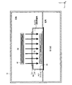
- FIG. 1 is a schematic front sectional view of the entire drying apparatus according to the present invention.
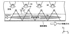
- FIG. 2 is a schematic sectional view in side view of the drying apparatus shown in FIG. 1.
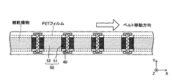
- FIG. 2 is a partial schematic cross-sectional view of the drying apparatus shown in FIG. It is a partial schematic sectional view of the drying apparatus shown in FIG. It is a figure corresponding to FIG. 2 which concerns on the modification of the drying apparatus which concerns on this invention.
- this embodiment dries a material to be dried by drying a material to be dried placed on a conveyor belt 20 that translates horizontally from the left side to the right side of the paper (in the positive x-axis direction). It is the apparatus which implements the drying process to obtain.
- the left-right direction of the paper surface (the moving direction of the conveyor belt 20 and the x-axis direction) is referred to as a “longitudinal direction”
- the depth direction of the paper surface (a direction perpendicular to the longitudinal direction and the y-axis direction) is referred to as a “width direction”.
- the material to be dried typically, a molded body of “slurry containing ceramic powder or metal powder, binder and solvent”, and a film-like body extending in the longitudinal direction is assumed.
- the solvent in the material to be dried is volatilized and removed, and the material to be dried is dried.
- the dried material to be dried is then fired (the binder is volatilized and removed) to be the final product (fired body).
- This embodiment includes an “infrared drying furnace” corresponding to the first half of the drying process and a “hot air drying furnace” corresponding to the latter half of the drying process.
- an “infrared drying furnace” corresponding to the first half of the drying process
- a “hot air drying furnace” corresponding to the latter half of the drying process.
- the configuration of the infrared drying furnace will be described first.
- a drying process may be comprised only with an “infrared drying furnace.”
- the infrared drying furnace includes a furnace body 10. As shown in FIG. 1, a carry-in port 11 and a carry-out port 12 are provided at both ends of the furnace body 10 in the longitudinal direction.
- the conveyor belt 20 extending horizontally in the longitudinal direction is horizontally directed from the carry-in port 11 toward the carry-out port 12 in the internal space of the furnace body 10 while being guided by a plurality of guide rolls 30 provided in the internal space of the furnace body 10. It is configured to be movable.
- the moving speed or the like of the conveyor belt 20 is adjusted by a belt driving controller 100 and a known belt driving mechanism (not shown).
- a plurality of infrared heaters 40 are respectively arranged at predetermined intervals in the longitudinal direction above the conveyor belt 20 in the internal space of the furnace body 10. As shown in FIGS. 2 and 3, each infrared heater 40 has a rod shape. Each infrared heater 40 is arranged such that each axis line is along the width direction. The intensity and wavelength of infrared rays emitted from the infrared heater 40 are adjusted by the infrared heater controller 200.
- the infrared heater 40 can generate infrared rays having various wavelengths, but typically generates infrared rays (near infrared rays) having a dominant wavelength of about 6 ⁇ m or less.
- a partition wall 50 that partitions the space S1 including the conveyor belt 20 and the space S2 including the infrared heater 40 is provided so as to extend horizontally in the longitudinal direction. It has been.
- the partition wall 50 is composed of a first portion 51 made of a material that transmits infrared rays (particularly near infrared rays) and a material that does not transmit infrared rays (particularly near infrared rays). And the second portion 52.
- the second portion 52 has a shape that extends horizontally in the longitudinal direction and has a central portion in the width direction (y-axis direction) projecting upward in a rectangular shape.
- a window (rectangular opening) is provided at each position corresponding to each infrared heater 40 in the longitudinal direction. Is formed.
- a rectangular thin plate-like first portion 51 is provided on the top surface of the second portion 52 so as to cover these windows. Therefore, as shown in FIG. 2, the infrared rays emitted from the respective infrared heaters 40 can pass through the corresponding first portions 51 to reach the object to be dried, thereby drying the object to be dried.
- the plurality of first portions 51 are arranged at positions corresponding to the infrared heaters 40 in the longitudinal direction, and the plurality of second portions 52 are between the adjacent infrared heaters 40, 40 in the longitudinal direction. It can be said that they are respectively arranged at positions corresponding to.
- quartz glass is suitable. Quartz glass has a characteristic of transmitting infrared light (near infrared light) having a dominant wavelength of 3.5 ⁇ m or less with high transmittance.
- stainless steel is suitable. Stainless steel has a characteristic of not transmitting infrared rays (near infrared rays) having a dominant wavelength of about 6 ⁇ m or less. Further, since stainless steel has a characteristic of absorbing infrared rays (near infrared rays) at a certain rate, it also has a heat retaining effect for the partition walls 50.
- an aluminum alloy is also suitable as a material for the second portion 52.
- Aluminum alloy not only has the property of not transmitting infrared rays (near infrared rays) having a dominant wavelength of about 6 ⁇ m or less, but also has a lower infrared (near infrared) absorption rate than stainless steel. For this reason, it can suppress that the partition 50 becomes high temperature. Therefore, it can be said that the aluminum alloy is suitable for drying an object to be dried at a relatively low temperature.
- the space S1 is further divided into “a space corresponding to the upper side of the conveyor belt 20” (a portion protruding in a rectangular shape in the central portion in the width direction of the second portion 52, the first portion 51, and the conveyor belt 20. Partitioned space) and “a space corresponding to the lower side of the conveyor belt 20”.
- space S1 the space corresponding to the upper side of the conveyor belt 20”
- space S3 the space corresponding to the lower side of the conveyor belt 20
- a plurality of air nozzles 60 are arranged at predetermined intervals in the longitudinal direction above each infrared heater 40 in the space S ⁇ b> 2 of the furnace body 10. From each nozzle 60, the temperature-adjusted air is discharged downward (see thin arrows). The temperature of the partition 50 is adjusted by the air thus discharged striking the partition 50. The air thus discharged is discharged to the outside through an exhaust port 13 provided on the upper surface of the furnace body 10 (see thin arrows).
- an air inlet 14 and an air outlet 15 are formed in the space S3 of the furnace body 10. Air whose temperature is adjusted is discharged from the intake port 14 in the negative x-axis direction (see thin arrows). The temperature of the conveyor belt 20 is adjusted by the air thus discharged striking the conveyor belt 20. The air thus discharged is discharged to the outside through the exhaust port 15 (see thin arrows). The temperature, flow rate, and the like of the air discharged from each nozzle 60 and the intake port 14 are adjusted by the air supply controller 300.
- a nozzle 70 for nitrogen gas is disposed near the carry-in port 11 of the furnace body 10. From the nozzle 70, nitrogen gas whose temperature and humidity are adjusted is discharged in the positive direction of the x-axis toward the inside of the space S1 (see thick white arrows). As described above, when the nitrogen gas flows in the positive direction of the x-axis through the space S1, the temperature and the solvent concentration of the “gas containing the solvent evaporated from the object to be dried” are made as uniform as possible in the region near the surface of the object to be dried. It has become so.
- the nitrogen gas that has passed through the space S1 is discharged to the internal space S4 of the furnace body 80 described later via the carry-out port 12 (see a thick white arrow).
- the temperature, humidity, flow rate (flow rate), and the like of the nitrogen gas discharged from the nozzle 70 are adjusted by the nitrogen gas supply controller 400.
- the hot air drying furnace includes a furnace body 80 connected to a side surface of the furnace body 10 on the x-axis positive direction side.
- the interior of the furnace body 80 is configured by one space S4.
- the above-described “exit 12 of the furnace body 10” functioning as a carry-in port and a carry-out port 81 are provided.
- a plurality of air nozzles 90 are arranged at predetermined intervals in the longitudinal direction above the space S ⁇ b> 4 of the furnace body 80. From each nozzle 90, air (hot air) adjusted to a high temperature is discharged downward (see thin arrows). As the air (hot air) discharged in this way hits the object to be dried, the drying of the object to be dried further proceeds. The air (hot air) discharged in this way is discharged to the outside through an exhaust port 82 provided on the upper surface of the furnace body 80 (see thin arrows). In addition, from this exhaust port 82, the nitrogen gas which flowed in in space S4 from the carrying-out port 81 is also discharged
- the configuration of the “hot air drying furnace” has been described above.
- an object to be dried (typically, a thin slurry-like molded body described above) is placed on the upper surface of the conveyor belt 20 via a PET film. Placed.
- the reason why the PET film is used is to facilitate handling of an object to be dried.
- the PET film is removed from the object to be dried.
- the PET film has a property of absorbing near infrared rays while transmitting near infrared rays. Also from this viewpoint, it is preferable that the infrared rays irradiated from the infrared heater 40 are near infrared rays.
- the conveyor belt 20 on which the object to be dried is placed moves in parallel in the x-axis positive direction at a predetermined speed.
- infrared rays near infrared rays
- irradiated infrared rays passes through the corresponding first portion 51 in the partition wall 50 and reaches the object to be dried. As a result, the material to be dried is dried.
- the nitrogen gas whose temperature and humidity are adjusted is discharged from the nozzle 70 toward the inside of the space S1 in the x-axis positive direction. Thereby, nitrogen gas flows through the space S1 in the positive x-axis direction.
- the temperature and the solvent concentration of the “gas containing the solvent evaporated from the object to be dried” are made as uniform as possible in the region near the surface of the object to be dried.
- local variations are less likely to occur in the drying speed of the object to be dried, and deformation of the object to be dried and occurrence of cracks after drying can be suppressed.
- this action / effect is larger as the thickness of the object to be dried is larger.
- the temperature at which the air discharged from the nozzle 60 reaches the partition wall 50 can be made substantially equal to the temperature at which the air discharged from the intake port 14 reaches the conveyor belt 20.
- the to-be-dried object moving with the conveyor belt 20 in the “infrared drying furnace” is maintained at a temperature slightly higher than room temperature, and the action of the flow of nitrogen gas in the space S1.
- the film is dried by the action of infrared rays with almost no local variation in the drying speed.
- Such objects to be dried move from the “infrared drying furnace” to the “hot air drying furnace”.
- air (hot air) adjusted to a high temperature is discharged from each nozzle 90 toward the inside of the space S4.
- the object to be dried moving with the conveyor belt 20 in the “hot air drying furnace” is further dried at a high temperature by the action of the discharged air (hot air).
- the drying of the material to be dried is completed. That is, a dried product is obtained.
- drying of the material to be dried is sufficiently advanced at the stage where it is transported from the “infrared drying furnace”. Will not occur.
- first portions 51 portions that transmit infrared rays
- the 2nd part 52 is each arrange
- the infrared heaters 40, 40 by adjusting the distance between the adjacent infrared heaters 40, 40 and the length of the first portion 51 of the partition wall 50 in the longitudinal direction, irradiation is performed from the adjacent infrared heaters 40, 40.
- the infrared rays can be irradiated over the entire surface of the object to be dried without causing the infrared rays to be overlapped in the longitudinal direction (or by overlapping a part of the infrared rays in the longitudinal direction).
- the intensity of infrared rays applied to the object to be dried can be made substantially uniform with respect to the longitudinal direction.
- the interval between adjacent infrared heaters 40 can be increased, and the number of infrared heaters 40 can be reduced.
- nitrogen gas is used as the gas flowing in the space S1, but it may be an inert gas, for example, argon.
- the partition 50 is comprised by the 1st part 51 (part which permeate
- the lower surface of both end portions in the width direction of the partition wall 50 second portion 52 and the both end portions of the upper surface of the conveyor belt 20 slightly overlap in the width direction, so that the space S1 is formed. Furthermore, although it is divided into “a space S1 corresponding to the upper side of the conveyor belt 20” and “a space S3 corresponding to the lower side of the conveyor belt 20,” the space S1 is “a space above the conveyor belt 20”. “And the space below the conveyor belt 20" may be one continuous space.
- the “temperature and concentration of the solvent-containing gas” in the region near the surface of the material to be dried inevitably varies in the width direction in the space S1. Therefore, due to the “variation in the width direction in the gas temperature and the solvent concentration”, the drying speed of the material to be dried can also vary in the width direction.
- the higher (smaller) the intensity of infrared rays irradiated to the object to be dried the faster (slower) the drying speed of the object to be dried.
- the “intensity distribution in the width direction in the infrared rays irradiated to the object to be dried” the “in the drying speed of the object to be dried” caused by “the variation in the width direction in the gas temperature and the solvent concentration” It is possible to cancel out the “variation in the width direction”.
- the solvent concentration of the “gas containing solvent” is higher in the width direction center than in the width direction both ends in the space S1
- the drying speed of the object to be dried is higher in the width direction both ends than in the width direction center. Will be bigger.
- the thickness of the object to be dried tends to be larger at both ends in the width direction than at the center in the width direction.
- the shielding member Z that does not transmit infrared rays is arranged on the upper surfaces of both end portions in the width direction of the first portion 51 of the partition wall 50, but for example, “gas containing solvent”
- the shielding member Z that does not transmit infrared rays (near infrared rays) to the upper surface of the width direction central portion of the first portion 51 of the partition wall 50 is preferably arranged.
- the shielding member Z a member that completely blocks infrared rays (near infrared rays) is used as the shielding member Z.
- the shielding member Z a member that slightly transmits infrared rays (near infrared rays) (first)
- a member having a smaller infrared (near infrared) transmittance than the member 51 may be used.
- the shielding member Z is disposed on the upper surface of the first portion 51 of the partition wall 50 in order to adjust “the intensity distribution in the width direction in the infrared rays irradiated to the object to be dried”.
Landscapes
- Engineering & Computer Science (AREA)
- Mechanical Engineering (AREA)
- General Engineering & Computer Science (AREA)
- Life Sciences & Earth Sciences (AREA)
- Microbiology (AREA)
- Textile Engineering (AREA)
- Chemical & Material Sciences (AREA)
- Combustion & Propulsion (AREA)
- Drying Of Solid Materials (AREA)
Abstract
Priority Applications (5)
| Application Number | Priority Date | Filing Date | Title |
|---|---|---|---|
| JP2015502928A JP6027675B2 (ja) | 2013-02-26 | 2014-02-25 | 乾燥装置 |
| CN201480010619.9A CN105026863B (zh) | 2013-02-26 | 2014-02-25 | 干燥装置 |
| EP14756367.0A EP2963372B1 (fr) | 2013-02-26 | 2014-02-25 | Dispositif de séchage |
| KR1020157022881A KR101769224B1 (ko) | 2013-02-26 | 2014-02-25 | 건조 장치 |
| US14/832,196 US9982941B2 (en) | 2013-02-26 | 2015-08-21 | Drying apparatus |
Applications Claiming Priority (4)
| Application Number | Priority Date | Filing Date | Title |
|---|---|---|---|
| JP2013035924 | 2013-02-26 | ||
| JP2013-035924 | 2013-02-26 | ||
| JP2013218253 | 2013-10-21 | ||
| JP2013-218253 | 2013-10-21 |
Related Child Applications (1)
| Application Number | Title | Priority Date | Filing Date |
|---|---|---|---|
| US14/832,196 Continuation US9982941B2 (en) | 2013-02-26 | 2015-08-21 | Drying apparatus |
Publications (1)
| Publication Number | Publication Date |
|---|---|
| WO2014132952A1 true WO2014132952A1 (fr) | 2014-09-04 |
Family
ID=51428216
Family Applications (1)
| Application Number | Title | Priority Date | Filing Date |
|---|---|---|---|
| PCT/JP2014/054467 Ceased WO2014132952A1 (fr) | 2013-02-26 | 2014-02-25 | Dispositif de séchage |
Country Status (7)
| Country | Link |
|---|---|
| US (1) | US9982941B2 (fr) |
| EP (1) | EP2963372B1 (fr) |
| JP (1) | JP6027675B2 (fr) |
| KR (1) | KR101769224B1 (fr) |
| CN (1) | CN105026863B (fr) |
| TW (1) | TWI576553B (fr) |
| WO (1) | WO2014132952A1 (fr) |
Cited By (5)
| Publication number | Priority date | Publication date | Assignee | Title |
|---|---|---|---|---|
| JP2017172855A (ja) * | 2016-03-23 | 2017-09-28 | 日本碍子株式会社 | 赤外線処理装置 |
| JP2018132272A (ja) * | 2017-02-17 | 2018-08-23 | 日本碍子株式会社 | 乾燥装置及び乾燥体の製造方法 |
| US10739069B2 (en) | 2016-03-28 | 2020-08-11 | Ngk Insulators, Ltd. | Low-temperature drying apparatus |
| JP2024100101A (ja) * | 2023-01-13 | 2024-07-26 | 日本碍子株式会社 | 乾燥装置 |
| WO2025177668A1 (fr) * | 2024-02-22 | 2025-08-28 | 東レエンジニアリング株式会社 | Appareil de séchage |
Families Citing this family (5)
| Publication number | Priority date | Publication date | Assignee | Title |
|---|---|---|---|---|
| CN107429971A (zh) * | 2015-03-27 | 2017-12-01 | 住友电工烧结合金株式会社 | 搬送式热处理装置 |
| US11492300B2 (en) | 2016-12-27 | 2022-11-08 | Sabic Global Technologies B.V. | Drying a coating using electromagnetic radiation or heating of drum |
| KR102761716B1 (ko) * | 2019-06-12 | 2025-02-03 | 주식회사 엘지화학 | 단열재 건조장치 및 이를 이용한 단열재 건조방법 |
| DE202023103004U1 (de) * | 2023-05-31 | 2023-07-18 | Gunther Ackermann | Umluft-Prozess-System |
| KR102891251B1 (ko) * | 2023-08-22 | 2025-12-01 | 주식회사 에스에프에이 | 이차전지 전극 제조용 하이브리드 건조시스템 |
Citations (3)
| Publication number | Priority date | Publication date | Assignee | Title |
|---|---|---|---|---|
| JP2000035279A (ja) * | 1998-07-15 | 2000-02-02 | Dainippon Printing Co Ltd | 乾燥装置 |
| JP2001314799A (ja) * | 2000-05-12 | 2001-11-13 | Fuji Photo Film Co Ltd | 塗布膜の熱処理方法及び装置 |
| JP2002015711A (ja) * | 2000-06-30 | 2002-01-18 | Matsushita Electric Ind Co Ltd | 赤外線電球及びそれを用いた装置 |
Family Cites Families (12)
| Publication number | Priority date | Publication date | Assignee | Title |
|---|---|---|---|---|
| ID27685A (id) * | 1998-07-30 | 2001-04-19 | Daito Seiki | Pengering, perakitan pengering dan metode pengeringan |
| DE19857045C2 (de) | 1998-12-10 | 2001-02-01 | Industrieservis Ges Fuer Innov | Beschichtung von Gegenständen |
| US6537600B1 (en) * | 1999-09-14 | 2003-03-25 | Charles R. Meldrum | Multiple-stage energy-efficient produce processing system |
| US6812982B2 (en) | 2000-05-12 | 2004-11-02 | Fuji Photo Film Co., Ltd. | Optical compensatory sheet producing method and apparatus, thermal treating method and apparatus, and dust removing method and apparatus |
| JP4350298B2 (ja) * | 2000-11-22 | 2009-10-21 | 大日本印刷株式会社 | 乾燥装置 |
| JP4631412B2 (ja) | 2004-11-29 | 2011-02-16 | 富士電機システムズ株式会社 | フロアモニタ |
| JP4696736B2 (ja) * | 2005-07-12 | 2011-06-08 | ウシオ電機株式会社 | 光加熱装置 |
| JP2008082569A (ja) * | 2006-09-26 | 2008-04-10 | Kojiro Okawa | 水切り乾燥装置及び水切り乾燥方法 |
| JP5249916B2 (ja) * | 2009-12-24 | 2013-07-31 | 三菱重工業株式会社 | 電極乾燥装置 |
| JP5107372B2 (ja) * | 2010-02-04 | 2012-12-26 | 東京エレクトロン株式会社 | 熱処理装置、塗布現像処理システム、熱処理方法、塗布現像処理方法及びその熱処理方法又は塗布現像処理方法を実行させるためのプログラムを記録した記録媒体 |
| KR20130095580A (ko) * | 2012-02-20 | 2013-08-28 | 고요 써모 시스템 가부시끼 가이샤 | 히터 유닛 및 열처리 장치 |
| CN202547304U (zh) * | 2012-04-06 | 2012-11-21 | 濮阳惠成电子材料股份有限公司 | 一种红外辐射固体干燥装置 |
-
2014
- 2014-02-25 WO PCT/JP2014/054467 patent/WO2014132952A1/fr not_active Ceased
- 2014-02-25 EP EP14756367.0A patent/EP2963372B1/fr active Active
- 2014-02-25 KR KR1020157022881A patent/KR101769224B1/ko active Active
- 2014-02-25 CN CN201480010619.9A patent/CN105026863B/zh active Active
- 2014-02-25 JP JP2015502928A patent/JP6027675B2/ja active Active
- 2014-02-26 TW TW103106422A patent/TWI576553B/zh active
-
2015
- 2015-08-21 US US14/832,196 patent/US9982941B2/en active Active
Patent Citations (4)
| Publication number | Priority date | Publication date | Assignee | Title |
|---|---|---|---|---|
| JP2000035279A (ja) * | 1998-07-15 | 2000-02-02 | Dainippon Printing Co Ltd | 乾燥装置 |
| JP3897456B2 (ja) | 1998-07-15 | 2007-03-22 | 大日本印刷株式会社 | 乾燥装置 |
| JP2001314799A (ja) * | 2000-05-12 | 2001-11-13 | Fuji Photo Film Co Ltd | 塗布膜の熱処理方法及び装置 |
| JP2002015711A (ja) * | 2000-06-30 | 2002-01-18 | Matsushita Electric Ind Co Ltd | 赤外線電球及びそれを用いた装置 |
Cited By (6)
| Publication number | Priority date | Publication date | Assignee | Title |
|---|---|---|---|---|
| JP2017172855A (ja) * | 2016-03-23 | 2017-09-28 | 日本碍子株式会社 | 赤外線処理装置 |
| US10739069B2 (en) | 2016-03-28 | 2020-08-11 | Ngk Insulators, Ltd. | Low-temperature drying apparatus |
| JP2018132272A (ja) * | 2017-02-17 | 2018-08-23 | 日本碍子株式会社 | 乾燥装置及び乾燥体の製造方法 |
| JP2024100101A (ja) * | 2023-01-13 | 2024-07-26 | 日本碍子株式会社 | 乾燥装置 |
| JP7760538B2 (ja) | 2023-01-13 | 2025-10-27 | 日本碍子株式会社 | 乾燥装置 |
| WO2025177668A1 (fr) * | 2024-02-22 | 2025-08-28 | 東レエンジニアリング株式会社 | Appareil de séchage |
Also Published As
| Publication number | Publication date |
|---|---|
| KR101769224B1 (ko) | 2017-08-17 |
| TW201506337A (zh) | 2015-02-16 |
| EP2963372A1 (fr) | 2016-01-06 |
| EP2963372B1 (fr) | 2019-01-02 |
| JP6027675B2 (ja) | 2016-11-16 |
| KR20150111975A (ko) | 2015-10-06 |
| CN105026863B (zh) | 2016-12-28 |
| JPWO2014132952A1 (ja) | 2017-02-02 |
| CN105026863A (zh) | 2015-11-04 |
| EP2963372A4 (fr) | 2017-01-11 |
| TWI576553B (zh) | 2017-04-01 |
| US20150354892A1 (en) | 2015-12-10 |
| US9982941B2 (en) | 2018-05-29 |
Similar Documents
| Publication | Publication Date | Title |
|---|---|---|
| JP6027675B2 (ja) | 乾燥装置 | |
| ES2805531T3 (es) | Dispositivo de secado | |
| US10739069B2 (en) | Low-temperature drying apparatus | |
| KR101859278B1 (ko) | 도공 장치 및 도공 방법 | |
| JP2021505837A5 (fr) | ||
| US20080104857A1 (en) | Multistage Continuous Microwave Dryer For Plate-Shaped Products, Especially Fiber Boards | |
| WO2015022857A1 (fr) | Dispositif à rayonnement infrarouge et dispositif de traitement par infrarouges | |
| JP5810074B2 (ja) | 乾燥装置 | |
| JP2009022856A (ja) | 塗装セッティング装置 | |
| JP2018526608A5 (fr) | ||
| JP6135764B2 (ja) | デスミア処理装置 | |
| CN104422277A (zh) | 热处理炉 | |
| JP2018132272A (ja) | 乾燥装置及び乾燥体の製造方法 | |
| JP2005049021A (ja) | ペースト材料の乾燥方法および乾燥装置 | |
| JP7449203B2 (ja) | 熱処理炉 | |
| JP6484664B2 (ja) | 乾燥装置及び該乾燥装置を用いた乾燥方法 | |
| KR20140043863A (ko) | 액자 발생 억제 방법 및 액자 발생 억제 장치 | |
| JP5977033B2 (ja) | 熱処理装置 | |
| JP7358288B2 (ja) | セラミックグリーンシートの製造方法及び製造装置 | |
| WO2016126843A4 (fr) | Procédé continu et appareil améliorés permettant de fabriquer des croustilles pita | |
| JP2006183934A (ja) | 溶媒除去装置および溶媒除去方法 | |
| JP2017172855A (ja) | 赤外線処理装置 | |
| JP5388980B2 (ja) | 蒸着フラックス測定装置 | |
| KR101268430B1 (ko) | 피혁의 연속 도장설비의 건조장치 | |
| JP2018071954A (ja) | ウエブの熱処理装置 |
Legal Events
| Date | Code | Title | Description |
|---|---|---|---|
| WWE | Wipo information: entry into national phase |
Ref document number: 201480010619.9 Country of ref document: CN |
|
| 121 | Ep: the epo has been informed by wipo that ep was designated in this application |
Ref document number: 14756367 Country of ref document: EP Kind code of ref document: A1 |
|
| ENP | Entry into the national phase |
Ref document number: 2015502928 Country of ref document: JP Kind code of ref document: A |
|
| ENP | Entry into the national phase |
Ref document number: 20157022881 Country of ref document: KR Kind code of ref document: A |
|
| WWE | Wipo information: entry into national phase |
Ref document number: 2014756367 Country of ref document: EP |
|
| NENP | Non-entry into the national phase |
Ref country code: DE |