WO2014136247A1 - Réceptacle de stockage d'un substrat - Google Patents
Réceptacle de stockage d'un substrat Download PDFInfo
- Publication number
- WO2014136247A1 WO2014136247A1 PCT/JP2013/056376 JP2013056376W WO2014136247A1 WO 2014136247 A1 WO2014136247 A1 WO 2014136247A1 JP 2013056376 W JP2013056376 W JP 2013056376W WO 2014136247 A1 WO2014136247 A1 WO 2014136247A1
- Authority
- WO
- WIPO (PCT)
- Prior art keywords
- substrate
- contact
- lid
- container
- substrates
- Prior art date
- Legal status (The legal status is an assumption and is not a legal conclusion. Google has not performed a legal analysis and makes no representation as to the accuracy of the status listed.)
- Ceased
Links
Images




Classifications
-
- H—ELECTRICITY
- H10—SEMICONDUCTOR DEVICES; ELECTRIC SOLID-STATE DEVICES NOT OTHERWISE PROVIDED FOR
- H10P—GENERIC PROCESSES OR APPARATUS FOR THE MANUFACTURE OR TREATMENT OF DEVICES COVERED BY CLASS H10
- H10P72/00—Handling or holding of wafers, substrates or devices during manufacture or treatment thereof
- H10P72/10—Handling or holding of wafers, substrates or devices during manufacture or treatment thereof using carriers specially adapted therefor, e.g. front opening unified pods [FOUP]
- H10P72/19—Handling or holding of wafers, substrates or devices during manufacture or treatment thereof using carriers specially adapted therefor, e.g. front opening unified pods [FOUP] closed carriers
- H10P72/1911—Handling or holding of wafers, substrates or devices during manufacture or treatment thereof using carriers specially adapted therefor, e.g. front opening unified pods [FOUP] closed carriers characterised by materials, roughness, coatings or the like
- H10P72/1912—Handling or holding of wafers, substrates or devices during manufacture or treatment thereof using carriers specially adapted therefor, e.g. front opening unified pods [FOUP] closed carriers characterised by materials, roughness, coatings or the like characterised by shock absorbing elements, e.g. retainers or cushions
-
- H—ELECTRICITY
- H10—SEMICONDUCTOR DEVICES; ELECTRIC SOLID-STATE DEVICES NOT OTHERWISE PROVIDED FOR
- H10P—GENERIC PROCESSES OR APPARATUS FOR THE MANUFACTURE OR TREATMENT OF DEVICES COVERED BY CLASS H10
- H10P72/00—Handling or holding of wafers, substrates or devices during manufacture or treatment thereof
- H10P72/10—Handling or holding of wafers, substrates or devices during manufacture or treatment thereof using carriers specially adapted therefor, e.g. front opening unified pods [FOUP]
- H10P72/19—Handling or holding of wafers, substrates or devices during manufacture or treatment thereof using carriers specially adapted therefor, e.g. front opening unified pods [FOUP] closed carriers
- H10P72/1921—Handling or holding of wafers, substrates or devices during manufacture or treatment thereof using carriers specially adapted therefor, e.g. front opening unified pods [FOUP] closed carriers characterised by substrate supports
Definitions
- the present invention relates to a substrate storage container, and more particularly to a substrate storage container that stores a plurality of substrates such as semiconductor wafers in parallel.
- a container for storing a substrate such as a semiconductor wafer
- a container including a container body, a lid, a side substrate support, a lid side substrate support, and a back substrate support
- the container body has a cylindrical wall portion in which a container body opening is formed at one end and the other end is closed.
- a substrate storage space is formed in the container body.
- the substrate storage space is formed by being surrounded by a wall portion, and can store a plurality of substrates.
- the lid can be attached to and detached from the container body opening, and the container body opening can be closed.
- the side substrate support portions are provided on the wall portion so as to form a pair in the substrate storage space.
- the side substrate support portion can support the edges of a plurality of substrates in a state where adjacent substrates are spaced apart and arranged in parallel when the container body opening is not closed by the lid. is there.
- the lid-side substrate support portion is provided in a portion of the lid that faces the substrate storage space when the container body opening is closed.
- the lid-side substrate support portion can support the edges of the plurality of substrates when the container main body opening is closed by the lid.
- the wall portion substrate support portion is provided on the wall portion so as to form a pair with the lid side substrate support portion.
- substrate support part can support the edge part of a some board
- Each of the wall portion substrate support portion and the lid side substrate support portion has a front contact surface and a back contact surface.
- the front-side contact surface can contact the edge of the surface of the substrate in a positional relationship that intersects the surface of the substrate.
- the back-side contact surface can contact the edge of the back surface of the substrate in a positional relationship intersecting the back surface of the substrate.
- the front-side contact surface is in a positional relationship that intersects the surface of the substrate and contacts the edge of the surface of the substrate, and therefore has a positional relationship that covers the surface of the substrate in the vicinity of the edge of the substrate.
- the portions constituting the front-side contact surface and the back-side contact surface of the wall-side substrate support portion and the lid-side substrate support portion are made of a resin material such as polycarbonate, so that gas is generated from the resin material, and the substrate It is considered that there is a possibility of adversely affecting a thin wafer attached to the surface of the wafer.
- the present invention provides a container main body in which a substrate storage space capable of storing a plurality of substrates is formed, a container main body opening formed at one end thereof and communicating with the substrate storage space, and the container main body opening.
- a lid that is detachable and is arranged so as to make a pair in the substrate storage space with a lid capable of closing the container body opening, and when the container body opening is not closed by the lid,
- a side substrate support portion capable of supporting an edge portion of the plurality of substrates in a state where adjacent substrates among the plurality of substrates are spaced apart and arranged in parallel with each other, and a portion of the lid
- the container body opening is disposed at a portion facing the substrate storage space, and when the container body opening is closed by the lid, the plurality of substrates Can support the edge A body-side substrate support portion and a lid-side substrate support portion arranged in a pair in the substrate storage space, and can support edges of the plurality of substrates, and the container body opening portion is
- the back of the plurality of substrates is supported in a state where the edge portions of the plurality of substrates are spaced apart from the side substrate support portions in parallel.
- a side substrate support portion, and at least one of the lid side substrate support portion and the back side substrate support portion can be opposed to the surface of the substrate in a positional relationship intersecting the surface of the substrate.
- an abutting surface capable of abutting on an edge of the back surface of the substrate, an angle formed by either one of the front surface or the back surface of the substrate and the inclined facing surface is a,
- An angle formed by the one surface of the substrate and the contact surface is b. Relates to a substrate storage container having a relation of a> b.
- the substrate has a substrate front-side curved surface connecting the front surface of the substrate and the substrate side surface, and a substrate back-side curved surface connecting the back surface of the substrate and the substrate side surface.
- An inclined facing surface-side curved surface that connects the abutting side surface and the inclined facing surface and has a shape that matches the substrate front-side curved surface and is capable of contacting the substrate front-side curved surface, the substrate contacting side surface, and the contact It is preferable to have a contact surface-side curved surface that is connected to a surface and has a shape that coincides with the substrate back-side curved surface and that can contact the substrate back-side curved surface.
- the substrate storage container has a surface abutting surface that is a flat surface that connects the substrate abutting side surface and the inclined facing surface and can abut against the surface of the substrate.
- the substrate abutting side surface and the inclined facing surface are connected, and can be brought into contact with the surface of the substrate by making point contact or line contact with the surface of the substrate from the surface of the substrate toward the back surface. It is preferable to provide a surface contact portion.
- the present invention it is possible to provide a substrate storage container that can suppress as much as possible the gas generated from the wall substrate support and the lid side substrate support from adversely affecting the wafer.
- FIG. 1 it is a conceptual diagram which shows the contact state with the inclination opposing surface 601 and the board
- FIG. It is a conceptual diagram which shows the state by which the board
- FIG. It is a conceptual diagram which shows the state by which the board
- FIG. 1 is an exploded perspective view showing a substrate storage container 1 according to the first embodiment.
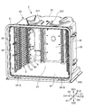
- FIG. 2 is a perspective view showing the container main body 2 of the substrate storage container 1 according to the first embodiment.
- FIG. 3 is a perspective view showing the container body 2 of the substrate storage container 1 according to the first embodiment.
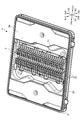
- FIG. 4 is a perspective view showing the lid 3 of the substrate storage container 1 according to the first embodiment.
- FIG. 5 is a conceptual diagram showing the wall substrate support 60 and the front retainer substrate receiver 73 of the substrate storage container 1 according to the first embodiment.
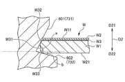
- FIG. 6 is a conceptual diagram showing a contact state of the inclined facing surface 601 at the edge of the substrate surface W11 with the substrate W in the substrate storage container 1 according to the first embodiment.
- a direction from the container body 2 described later to the lid 3 is defined as the front direction D11, and the opposite direction is defined as the rear direction D12. These are defined as the front-rear direction D1.
- a direction (upward direction in FIG. 1) from the lower wall 24 to the upper wall 23, which will be described later, is defined as an upward direction D21
- the opposite direction is defined as a downward direction D22, and these are defined as a vertical direction D2.
- a direction from the second side wall 26 to be described later to the first side wall 25 is defined as the left direction D31, and the opposite direction is defined as the right direction D32. Is defined as the left-right direction D3.
- explanations are given with arrows indicating these directions.
- the substrate W stored in the substrate storage container 1 has a substrate body W1, a thin substrate W2, and an adhesive W3.
- the substrate W is configured by laminating a substrate body W1, an adhesive W3, and a thin substrate W2 in this order, and has a disk shape as a whole.
- the substrate body W1 and the thin substrate W2 are each a disc-shaped silicon wafer, a glass wafer, a sapphire wafer, and the like, and are thin ones used in the industry.
- the substrate body W1 in the present embodiment is a silicon wafer having a diameter of 300 mm.
- the thin substrate W2 in the present embodiment is a silicon wafer having a diameter slightly smaller than 300 mm.
- the thin substrate W2 is bonded to the substrate body W1 with an adhesive W3.
- the adhesive W3 is applied to a circle area slightly smaller than the upper end surface of the substrate body W1 and slightly larger than the thin substrate W2.
- the peripheral portion of the upper end surface of the substrate main body W1, where the adhesive W3 is not applied and the thin substrate W2 is not attached, is the surface of the substrate W (mainly And W11 is formed. Further, the portion where the adhesive W3 on the peripheral edge of the upper end surface of the substrate body W1 is applied and the portion where the thin substrate W2 is not attached constitutes the surface W11 of the substrate W.
- the entire upper surface of the thin substrate W2 constitutes a surface W11 of the substrate W.
- the surface on the opposite side to the front surface W11 of the disk-shaped substrate W constitutes the back surface W21.
- the peripheral portion of the substrate W has a substrate side surface W31 that connects the front surface W11 and the back surface W21 of the substrate W.
- the substrate W has a substrate front-side curved surface W32 that connects the front surface W11 of the substrate W and the substrate side surface W31, and a substrate back-side curved surface W33 that connects the back surface W21 of the substrate W and the substrate side surface W31.
- the substrate storage container 1 includes a container body 2, a lid 3, a seal member 4, a substrate support plate-like portion 5 as a side substrate support portion, and a back substrate support. It has a portion 6 and a front retainer 7 (see FIG. 4).
- the container main body 2 has a cylindrical wall portion 20 in which a container main body opening 21 is formed at one end and the other end is closed.
- a substrate storage space 27 is formed in the container body 2.
- the substrate storage space 27 is formed so as to be surrounded by the wall portion 20.
- the substrate support plate-shaped portion 5 is disposed in a portion of the wall portion 20 that forms the substrate storage space 27.
- a plurality of substrates W can be stored in the substrate storage space 27.
- the substrate support plate-like portion 5 is provided on the wall portion 20 so as to form a pair in the left-right direction D3 in the substrate storage space 27.
- the substrate support plate-like portion 5 is arranged in such a manner that adjacent substrates W are separated from each other at a predetermined interval and arranged in parallel.
- the part can be supported.
- a back side substrate support portion 6 (see FIG. 2) is provided on the back side of the substrate support plate-like portion 5.
- the back-side substrate support 6 can support the rear portions of the edges of the plurality of substrates W when the container body opening 21 is closed by the lid 3.
- the lid 3 is detachable with respect to the opening peripheral edge 28 forming the container main body opening 21.
- the lid 3 can close the container main body opening 21 in a positional relationship surrounded by the opening peripheral edge 28, that is, in a state of being fitted into the container main body opening 21 formed by the opening peripheral edge 28.
- the front retainer 7 (see FIG. 4) is provided in a portion of the lid 3 that faces the substrate storage space 27 when the container main body opening 21 is closed by the lid 3.
- the front retainer 7 is disposed inside the substrate storage space 27 so as to make a pair with the back substrate support 6.
- the front retainer 7 can support the front portions of the edges of the plurality of substrates W when the container main body opening 21 is closed by the lid 3.
- the front retainer 7 supports a plurality of substrates W in cooperation with the back substrate support 6 and thereby sets adjacent substrates W together.
- a plurality of substrates W are held in a state where they are spaced apart and arranged in parallel.
- the substrate W is supported in the substrate storage space 27 in such a positional relationship that the normal of the front surface W11 coincides with the upward direction D21 and the normal of the back surface W21 coincides with the downward direction D22.
- the wall portion 20 of the container body 2 includes a back wall 22, an upper wall 23, a lower wall 24, a first side wall 25, and a second side wall 26.
- the back wall 22, the upper wall 23, the lower wall 24, the first side wall 25, and the second side wall 26 are made of a plastic material or the like. In the first embodiment, they are integrally formed of polycarbonate.
- the first side wall 25 and the second side wall 26 face each other, and the upper wall 23 and the lower wall 24 face each other.
- the rear end of the upper wall 23, the rear end of the lower wall 24, the rear end of the first side wall 25, and the rear end of the second side wall 26 are all connected to the back wall 22.
- the front end of the upper wall 23, the front end of the lower wall 24, the front end of the first side wall 25, and the front end of the second side wall 26 have a positional relationship facing the back wall 22 and have a substantially rectangular shape. Opening peripheral edge portion 28 is formed.
- the opening peripheral edge 28 is provided at one end of the container main body 2, and the back wall 22 is located at the other end of the container main body 2.
- the outer shape of the container body 2 formed by the outer surface of the wall portion 20 is box-shaped.
- the inner surface of the wall portion 20, that is, the inner surface of the back wall 22, the inner surface of the upper wall 23, the inner surface of the lower wall 24, the inner surface of the first side wall 25, and the inner surface of the second side wall 26 are surrounded by these. 27 is formed.
- the container main body opening 21 formed in the opening peripheral edge portion 28 is surrounded by the wall portion 20 and communicates with the substrate storage space 27 formed in the container main body 2. A maximum of 25 substrates W can be stored in the substrate storage space 27.
- the opening peripheral edge portion 28 has latch engagement recesses 231A, 231B, 241A, and 241B as engagement recesses formed facing the lid 3.
- the latch engaging recesses 231 ⁇ / b> A, 231 ⁇ / b> B, 241 ⁇ / b> A, 241 ⁇ / b> B are recessed outward from the substrate storage space 27.
- a total of four latch engaging recesses 231A, 231B, 241A, 241B are formed near the left and right ends of the upper wall 23 and the lower wall 24, one each. Since the latch engagement recesses 231A, 231B, 241A, and 241B have the same shape, only the latch engagement recess 231A will be described below.
- a rib 236 and a flange fixing portion 237 are integrally formed with the upper wall 23.
- the rib 236 protrudes from the outer surface of the upper wall 23 in the upward direction D21 and extends substantially in the front-rear direction D1.
- a top flange 235 is fixed to the flange fixing portion 237.
- the top flange 235 is a flange engaging portion (not shown) provided when the substrate storage container 1 is suspended in a transfer device such as an AMHS (automatic wafer transfer system) or PGV (wafer substrate transfer carriage). It is a part which is hung by being gripped by the hanger.
- a container main body leg 243 is provided on the outer surface of the lower wall 24.
- the container main body legs 243 are integrally formed with the left and right end edges of the lower wall 24 and extend in the front-rear direction D1 along the left and right end edges of the lower wall 24.
- the substrate support plate-like portions 5 are provided on the first side wall 25 and the second side wall 26, respectively, and are arranged in the substrate storage space 27 so as to form a pair in the left-right direction D3.
- the substrate support plate-like portion 5 has a plate portion 51 and a plate portion support portion 52.
- the plate portion 51 and the plate portion support portion 52 are configured by integrally molding resin.
- the plate part 51 has a plate-like arc shape.
- a total of 50 plate portions 51 are provided on each of the first side wall 25 and the second side wall 26, each including 25 plates. Adjacent plate portions 51 are arranged in parallel with each other in the vertical direction D2 so as to be spaced apart from each other at an interval of 10 mm to 12 mm.
- the thing of the substantially same shape as the board part 51 is also arrange
- the 25 plate portions 51 provided on the first side wall 25 and the 25 plate portions 51 provided on the second side wall 26 have a positional relationship facing each other in the left-right direction D3.
- the 50 plate portions 51 and the members serving as two guides having substantially the same shape as the plate portion 51 have a positional relationship parallel to the inner surface of the lower wall 24.
- a convex portion 511 is provided on the upper surface of the plate portion 51.
- substrate W supported by the board part 51 contacts only the protrusion end of the convex part 511, and does not contact the board part 51 by a surface.
- the rear substrate support 6 has a wall substrate support 60.
- the wall portion substrate support portion 60 is formed integrally with the plate portion 51 at the rear end portion of the plate portion 51 of the substrate support plate-like portion 5.
- the back substrate support 6 is separate from the substrate support plate 5, that is, the wall substrate support 60 is formed separately from the plate 51 of the substrate support 5. Also good.
- the wall portion substrate support portions 60 are provided in a number corresponding to each of the substrates W that can be stored in the substrate storage space 27, specifically, 25 pieces.
- substrate support part 60 provided in the 1st side wall 25 and the 2nd side wall 26 has the positional relationship which makes a pair with the front retainer 7 mentioned later in the front-back direction D1. As described later, the substrate W is stored in the substrate storage space 27 and the lid 3 is closed, so that the wall substrate support 60 holds the edge of the edge of the substrate W.
- Each of the 25 wall substrate support parts 60 has an inclined facing surface 601 and a contact surface 602 as shown in FIG.
- the end edge of the inclined facing surface 601 and the end edge of the contact surface 602 are directly connected and have an integral structure.
- the inclined facing surface 601 is configured by a flat surface extending obliquely upward from an edge connected to the contact surface 602.
- the contact surface 602 is configured by a flat surface extending obliquely downward from an edge connected to the inclined facing surface 601.
- FIGS. 5 to 10 in addition to the reference numerals of the members related to the wall portion substrate support section 60, reference numerals of the members related to the front retainer substrate receiving section 73 described later are shown in parentheses.
- the angle b formed is 30 °.
- a one-dot chain line parallel to the surface W ⁇ b> 11 of the substrate W is illustrated. Since the front surface W11 and the back surface W22 of the substrate W have a parallel positional relationship, the front surface W11 is “one surface”. However, the present invention is not limited to this, and the back surface W22 may be “one surface”.
- the lid 3 has a substantially rectangular shape that substantially matches the shape of the opening peripheral edge 28 of the container body 2.
- the lid 3 can be attached to and detached from the opening peripheral edge 28 of the container main body 2, and the lid 3 can close the container main body opening 21 by attaching the lid 3 to the opening peripheral edge 28.
- a seal member fitting groove (not shown) is formed along the outer peripheral edge of the lid 3 at the outer peripheral edge of the lid 3.
- an annular seal member 4 made of elastically deformable POE (polyoxyethylene), PEE, fluorine rubber, silicon rubber or the like is fitted.
- the seal member 4 is arranged so as to go around the outer peripheral edge of the lid 3.
- the lid body 3 When the lid body 3 is attached to the opening peripheral edge portion 28, the outer peripheral edge portion of the lid body 3 comes into contact with the inner peripheral edge portion of the opening peripheral edge portion 28 of the container body 2 via the seal member 4. Thereby, the seal member 4 is sandwiched between the outer peripheral edge portion of the lid body 3 and the inner peripheral edge portion of the opening peripheral edge portion 28 and elastically deforms, and the lid body 3 closes the container body opening portion 21 in a sealed state.
- the substrate W By removing the lid 3 from the opening peripheral edge 28, the substrate W can be taken into and out of the substrate storage space 27 in the container body 2.
- the lid 3 is provided with a latch mechanism.
- the latch mechanism is provided in the vicinity of both left and right end portions of the lid 3, and as shown in FIG. 1, the two upper latch portions 32 ⁇ / b> A that can project in the upward direction D ⁇ b> 21 from the upper side of the lid 3, And two lower latch portions 32B that can project in the downward direction D22 from the lower side.
- the two upper latch portions 32 ⁇ / b> A are disposed in the vicinity of the left and right ends of the upper side of the lid 3, and the two lower latch portions 32 ⁇ / b> B are disposed in the vicinity of the left and right ends of the lower side of the lid 3.
- An operation unit 33 is provided on the outer surface of the lid 3.
- the upper latch portion 32 ⁇ / b> A and the lower latch portion 32 ⁇ / b> B can be protruded from the upper and lower sides of the lid 3, and the upper and lower sides are not projected from the upper and lower sides. Can be made.
- the upper latch portion 32A protrudes from the upper side of the lid body 3 in the upward direction D21 and engages with the latch engagement recesses 231A and 231B of the container body 2, and the lower latch portion 32B extends downward from the lower side of the lid body 3
- the lid 3 is fixed to the opening peripheral portion 28 of the container body 2 by projecting to D2 and engaging with the latch engaging recesses 241A and 241B of the container body 2.
- a recess 34 that is recessed outward from the substrate storage space 27 is formed inside the lid 3.
- the concave portion 34 has a width that is about half of the width in the left-right direction D3 of the lid 3 at the center position in the left-right direction D3 of the lid 3, and the vicinity of the lower end of the lid 3 in the vertical direction D2 It has been formed until.
- the front retainer 7 is provided in the recess 34. That is, the front retainer 7 is a portion of the lid 3 that faces the portion that forms the substrate storage space 27 when the container main body opening 21 of the container main body 2 is closed, that is, the substrate storage space 27. It is arranged in the part to be.
- the front retainer 7 has a pair of vertical frame bodies 71 extending in parallel with the vertical direction D2 and a front retainer substrate receiving portion 73 as a lid side substrate support portion.
- the pair of vertical frame bodies 71 and the front retainer substrate receiving portion 73 are integrally formed of resin.
- the pair of vertical frame bodies 71 are fixed to the lid body 3.
- the front retainer substrate receiving portion 73 constitutes a lid side substrate support portion.
- Front retainer substrate receiving portions 73 are arranged two by two so as to form a pair spaced apart at a predetermined interval in the left-right direction D3.
- the front retainer substrate receiving portions 73 arranged in pairs so as to form a pair in this way are provided in a state where 25 pairs are juxtaposed in the vertical direction D2.
- the front retainer substrate receiving portion 73 has an inclined facing surface 731 and a contact surface 732, similarly to the wall portion substrate supporting portion 60.
- the edge of the inclined facing surface 731 and the edge of the contact surface 732 are directly connected and have an integral configuration.
- the inclined facing surface 731 is configured by a flat surface extending inclined from the edge connected to each other upward.
- the contact surface 732 is configured by a flat surface extending obliquely downward from end edges connected to each other.
- the inclined facing surface 731 can face the surface W11 of the substrate W in a positional relationship intersecting the surface W11 of the substrate W as shown in FIG.
- the contact surface 732 can contact the edge of the back surface W21 of the substrate W.
- An angle formed by an acute angle between either one of the front surface W11 and the rear surface W22 of the substrate W (here, the front surface W11 is “one surface”) and the inclined facing surface 731 is a, and one of the substrates W
- the relationship is a> b.
- the angles a and b formed are the same as the angles a and b formed by the wall substrate support 60.
- the formed angle “a” has a value of 60 ° or more and 90 ° or less, and is 75 ° in the present embodiment.
- the angle b formed is 30 °.
- the front surface W11 and the back surface W22 of the substrate W have a parallel positional relationship, the front surface W11 is defined as “one surface”.
- the present invention is not limited to this, and the back surface W22 is defined as “one surface”. It is good also as.
- the back-side substrate support portion 6 and the front retainer substrate receiving portion 73 as the lid-side substrate support portion can each face the surface W11 of the substrate W in a positional relationship intersecting the surface W11 of the substrate W.
- the inclined opposing surfaces 601 and 731 and the contact surfaces 602 and 732 that can contact the edge of the back surface W21 of the substrate W are provided.
- the angle formed by one of the front surface W11 and the rear surface W22 of the substrate W (front surface W11) and the inclined opposing surfaces 601 and 731 is a, and is in contact with one surface (front surface W11) of the substrate W.
- the angle formed by the surfaces 602 and 732 is b, a relationship of a> b is established.
- the substrate W when the substrate W is viewed from above, which is a direction orthogonal to the surface W11 of the substrate W, the area that the inclined facing surfaces 601 and 731 cover the surface W11 of the substrate W can be reduced. As a result, the adverse effect on the thin substrate W2 due to the gas generated from the resin material constituting the wall portion substrate support portion 60 and the front retainer substrate receiving portion 73 can be suppressed as much as possible.
- the inclined facing surfaces 601 and 731 conventionally contact the substrate W at the position B, but can contact at the position A in this embodiment. As a result, it is possible to prevent the inclined facing surfaces 601 and 731 from coming into contact with the edge portion of the adhesive W3 of the substrate W (the left end portion of the adhesive W3 shown in FIG. 6), and the substrate main body W1 is bonded. It is possible to prevent the agent W3 from peeling off and the thin substrate W2 from peeling off.
- the substrate W can be easily positioned by the inclined facing surfaces 601 and 731 and the contact surfaces 602 and 732, The edge portion of the substrate W can be supported.
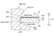
- FIG. 7 is a conceptual diagram illustrating a state in which the substrate W is supported by the wall substrate support 60A of the substrate storage container according to the second embodiment.
- the substrate storage container according to the second embodiment is different from the substrate storage container 1 according to the first embodiment in that it includes substrate contact side surfaces 603A and 733A that connect the inclined opposing surfaces 601 and 731 and the contact surfaces 602 and 732, respectively. Different.
- the same components as those in the first embodiment are denoted by the same reference numerals and description thereof is omitted.
- the front retainer substrate receiving portion 73 since the front retainer substrate receiving portion 73 has the same configuration as the wall portion substrate support portion 60, only the wall portion substrate support portion 60 will be described. Description of the front retainer substrate receiving portion 73 is omitted.
- the substrate storage container includes the substrate contact side surfaces 603A and 733A that connect the inclined facing surfaces 601 and 731 and the contact surfaces 602 and 732, respectively, and can contact the substrate side surface W31. It is possible to prevent the inclined facing surfaces 601 and 731 from coming into contact with the surface W11. Similarly, the contact surfaces 602 and 732 can be prevented from contacting the back surface W21 of the substrate W.
- the substrate storage container connects the substrate contact side surfaces 603A and 733A and the inclined facing surfaces 601 and 731 and has a shape that matches the substrate front surface curved surface W32 and contacts the substrate front surface curved surface W32.
- Possible inclined facing surface side curved surfaces 604A, 734A, substrate contact side surfaces 603A, 733A and contact surfaces 602, 732 are connected to each other and have a shape corresponding to the substrate back surface curved surface W33 and contact the substrate back surface curved surface W33 It has possible contact surface side curved surfaces 605A and 735A.
- the inclined facing surface-side curved surfaces 604A and 734A can contact the substrate front-side curved surface W32 on the surface, and the contact surface-side curved surfaces 605A and 735A contact the substrate back-side curved surface W33 on the surface. Is possible.
- the substrate W is accurately positioned with respect to the wall portion substrate support portion 60A and the front retainer substrate receiving portion 73A by the surface contact, and is supported by the wall portion substrate support portion 60A and the front retainer substrate receiving portion 73A. be able to.
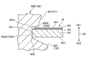
- FIG. 8 is a conceptual diagram illustrating a state in which the substrate W is supported by the wall substrate support 60B of the substrate storage container according to the third embodiment.
- the substrate storage container according to the third embodiment is different from the substrate storage container according to the second embodiment in that it has a surface contact surface 606B that connects the substrate contact side surfaces 603A and 733A and the inclined facing surfaces 601 and 731 respectively. . Further, the second embodiment is that the inclined facing surfaces 601 and 731 and the contact surfaces 602 and 732 and the substrate contact side surfaces 603A and 733A are not connected to each other by the substrate front side curved surface W32 and the substrate back side curved surface W33. It is different from the substrate storage container. Since it is the same as that of the board
- the surface contact surface 606B has one end edge connected to the substrate contact side surface 603A and the other end edge connected to the inclined facing surface 601.
- the surface contact surface 606B is a flat surface, and has a positional relationship parallel to the upper surface of the thin substrate W2 constituting the surface W11 of the substrate W.
- the surface contact surfaces 606B and 736B are flat surfaces, and have a positional relationship parallel to the upper surface of the thin substrate W2 constituting the surface W11 of the substrate W. With this configuration, when the substrate W is held by the wall substrate support portion 60B and the front retainer substrate receiving portion 73B, the surface contact surfaces 606B and 736B are the upper surfaces of the thin substrate W2 constituting the surface W11 of the substrate W. In addition, the surface can be contacted.
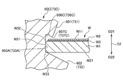
- FIG. 9 is a conceptual diagram illustrating a state in which the substrate W is supported by the wall substrate support 60C of the substrate storage container according to the fourth embodiment.
- One hemispherical convex portion 607C is provided on the surface contact surface 606C, and protrudes downward from the surface contact surface 606C.
- the hemispherical convex portion 607C is formed integrally with the portion of the wall portion substrate support portion 60C having the surface contact surface 606C.
- the hemispherical convex portion 607C has a front surface W11 of the substrate W from the front surface W11 of the substrate W toward the rear surface W21 (downward in FIG. 9) when the substrate W is held by the wall portion substrate support unit 60. Can be contacted by point contact.
- the surface contact surface 606C and the hemispherical convex portion 607C form a surface contact portion that can contact the surface W11 of the substrate W by connecting the substrate contact side surface 603A and the inclined facing surface 601.
- the wall extends in a direction intersecting the upper surface of the thin substrate W2 constituting the surface W11 of the substrate W. It is possible to suppress contact of members such as the inclined facing surfaces 601 and 731 constituting the partial substrate support portion 60C and the front retainer substrate receiving portion 73C as much as possible. As a result, it is possible to prevent the adhesive W3 from being peeled off from the substrate body W1, and the thin substrate W2 from being peeled off from the substrate body W1.
- the substrate storage container according to the fifth embodiment is that the buffer members 608D and 738D are provided so that the substrate side surface W31 does not directly contact the substrate contact side surfaces 603A and 733A. Is different.
- the second embodiment is that the inclined facing surfaces 601 and 731 and the contact surfaces 602 and 732 and the substrate contact side surfaces 603A and 733A are not connected to each other by the substrate front side curved surface W32 and the substrate back side curved surface W33. It is different from the substrate storage container. Since it is the same as that of the board
- the buffer member 608D is provided on the entire surface of the substrate contact side surface 603A, and is made of a material such as soft resin, rubber, or gel.
- the buffer member 608D is made of an elastomeric resin.
- the substrate storage container according to the fifth embodiment having the above configuration can provide the following effects. Since the buffer members 608D and 738D are provided on the substrate contact side surfaces 603A and 733A, the shock when the substrate W is supported by the wall substrate support 60 and the front retainer substrate receiver 73 is affected by the buffer members 608D and 738D. Can be absorbed. Further, the grip effect of supporting the substrate W by the wall portion substrate supporting portion 60 and the front retainer substrate receiving portion 73 can be obtained.
- both the wall substrate support 60 and the front retainer substrate receiver 73 have the inclined opposing surfaces 601 and 731 and the contact surfaces 602 and 732 having the same configuration. It is not limited.
- any one of the wall portion substrate support portion and the front retainer substrate receiving portion may have the inclined facing surfaces 601 and 731 or the contact surfaces 602 and 732 in the above-described embodiment.
Landscapes
- Container, Conveyance, Adherence, Positioning, Of Wafer (AREA)
- Packaging Frangible Articles (AREA)
Abstract
L'invention concerne un réceptacle de stockage d'un substrat muni d'une unité principale de réceptacle, d'un couvercle, de parties de support latéraux du substrat, d'une partie de support du substrat côté couvercle et d'une partie de support du substrat côté extrémité. La partie de support du substrat côté couvercle et/ou la partie de support du substrat côté extrémité présente une surface inclinée (601 ou 731) qui peut faire face à une face avant (W11) du substrat (W) dans une relation de position en intersection avec la face avant (W11) du substrat, et une surface de butée (602 ou 732) pouvant venir en butée contre un bord d'une face arrière (W21) du substrat (W). Lorsque l'angle formé par la face (W11) de la face avant (W11) du substrat (W) ou la face arrière (W22) du substrat (W) et la surface inclinée (601 ou 732) est a, et que l'angle formé par la face (W11) du substrat (W) et la surface de butée (602 ou 732) est b, a et b répondent à la relation a > b.
Priority Applications (1)
| Application Number | Priority Date | Filing Date | Title |
|---|---|---|---|
| PCT/JP2013/056376 WO2014136247A1 (fr) | 2013-03-07 | 2013-03-07 | Réceptacle de stockage d'un substrat |
Applications Claiming Priority (1)
| Application Number | Priority Date | Filing Date | Title |
|---|---|---|---|
| PCT/JP2013/056376 WO2014136247A1 (fr) | 2013-03-07 | 2013-03-07 | Réceptacle de stockage d'un substrat |
Publications (1)
| Publication Number | Publication Date |
|---|---|
| WO2014136247A1 true WO2014136247A1 (fr) | 2014-09-12 |
Family
ID=51490805
Family Applications (1)
| Application Number | Title | Priority Date | Filing Date |
|---|---|---|---|
| PCT/JP2013/056376 Ceased WO2014136247A1 (fr) | 2013-03-07 | 2013-03-07 | Réceptacle de stockage d'un substrat |
Country Status (1)
| Country | Link |
|---|---|
| WO (1) | WO2014136247A1 (fr) |
Cited By (3)
| Publication number | Priority date | Publication date | Assignee | Title |
|---|---|---|---|---|
| WO2017006406A1 (fr) * | 2015-07-03 | 2017-01-12 | ミライアル株式会社 | Récipient de stockage de substrat |
| CN110574152A (zh) * | 2017-04-05 | 2019-12-13 | 未来儿股份有限公司 | 基板收纳容器 |
| WO2024247264A1 (fr) * | 2023-06-02 | 2024-12-05 | ミライアル株式会社 | Récipient de stockage de substrat |
Citations (4)
| Publication number | Priority date | Publication date | Assignee | Title |
|---|---|---|---|---|
| JP2005005525A (ja) * | 2003-06-12 | 2005-01-06 | Shin Etsu Polymer Co Ltd | 基板収納容器 |
| JP2007145397A (ja) * | 2005-11-30 | 2007-06-14 | Hoya Corp | 基板収納容器、マスクブランク収納体、および転写マスク収納体 |
| JP2010199189A (ja) * | 2009-02-24 | 2010-09-09 | Shin Etsu Polymer Co Ltd | 基板収納容器及び基板の取り出し方法 |
| WO2010131291A1 (fr) * | 2009-05-13 | 2010-11-18 | ミライアル株式会社 | Récipient de boîtier de plaquette de semi-conducteur |
-
2013
- 2013-03-07 WO PCT/JP2013/056376 patent/WO2014136247A1/fr not_active Ceased
Patent Citations (4)
| Publication number | Priority date | Publication date | Assignee | Title |
|---|---|---|---|---|
| JP2005005525A (ja) * | 2003-06-12 | 2005-01-06 | Shin Etsu Polymer Co Ltd | 基板収納容器 |
| JP2007145397A (ja) * | 2005-11-30 | 2007-06-14 | Hoya Corp | 基板収納容器、マスクブランク収納体、および転写マスク収納体 |
| JP2010199189A (ja) * | 2009-02-24 | 2010-09-09 | Shin Etsu Polymer Co Ltd | 基板収納容器及び基板の取り出し方法 |
| WO2010131291A1 (fr) * | 2009-05-13 | 2010-11-18 | ミライアル株式会社 | Récipient de boîtier de plaquette de semi-conducteur |
Cited By (6)
| Publication number | Priority date | Publication date | Assignee | Title |
|---|---|---|---|---|
| WO2017006406A1 (fr) * | 2015-07-03 | 2017-01-12 | ミライアル株式会社 | Récipient de stockage de substrat |
| JPWO2017006406A1 (ja) * | 2015-07-03 | 2018-04-19 | ミライアル株式会社 | 基板収納容器 |
| US10490433B2 (en) | 2015-07-03 | 2019-11-26 | Miraial Co., Ltd | Substrate storing container |
| CN110574152A (zh) * | 2017-04-05 | 2019-12-13 | 未来儿股份有限公司 | 基板收纳容器 |
| CN110574152B (zh) * | 2017-04-05 | 2023-10-27 | 未来儿股份有限公司 | 基板收纳容器 |
| WO2024247264A1 (fr) * | 2023-06-02 | 2024-12-05 | ミライアル株式会社 | Récipient de stockage de substrat |
Similar Documents
| Publication | Publication Date | Title |
|---|---|---|
| JP5301731B2 (ja) | 基板収納容器 | |
| JP6177248B2 (ja) | 基板収納容器 | |
| KR102677319B1 (ko) | 기판 수납 용기 | |
| TWI878536B (zh) | 基板收納容器 | |
| JPWO2013183138A1 (ja) | 衝撃吸収機能を備えた基板収納容器 | |
| JP6106271B2 (ja) | 基板収納容器 | |
| KR20150087215A (ko) | 기판 수납 용기 | |
| US11348815B2 (en) | Board storing container | |
| WO2014136247A1 (fr) | Réceptacle de stockage d'un substrat | |
| TWI616385B (zh) | 基板收納容器 | |
| KR20160054461A (ko) | 기판수납용기 | |
| JP2016149492A (ja) | 基板収納容器 | |
| JP2016119408A (ja) | 基板収納容器 | |
| JP4728840B2 (ja) | 薄板保持容器 | |
| JP6391333B2 (ja) | 基板収納容器及びリテーナ | |
| TW202032700A (zh) | 基板收納容器 | |
| TW201529455A (zh) | 基板收納容器 | |
| TWI781205B (zh) | 基板收納容器 | |
| JP2007142192A (ja) | 薄板体収納容器 | |
| JPWO2018131363A1 (ja) | 基板収納容器 | |
| KR102942671B1 (ko) | 기판수납용기 및 그 뚜껑 | |
| JP2011031964A (ja) | 基板支持枠及び基板収納容器 | |
| JP2016058629A (ja) | 基板収納容器 | |
| TW202348529A (zh) | 基板收納容器以及蓋體側基板支承部 | |
| WO2025109707A1 (fr) | Récipient de stockage de substrat |
Legal Events
| Date | Code | Title | Description |
|---|---|---|---|
| 121 | Ep: the epo has been informed by wipo that ep was designated in this application |
Ref document number: 13877024 Country of ref document: EP Kind code of ref document: A1 |
|
| NENP | Non-entry into the national phase |
Ref country code: DE |
|
| 122 | Ep: pct application non-entry in european phase |
Ref document number: 13877024 Country of ref document: EP Kind code of ref document: A1 |
|
| NENP | Non-entry into the national phase |
Ref country code: JP |