WO2014136350A1 - ウォーターサーバー - Google Patents
ウォーターサーバー Download PDFInfo
- Publication number
- WO2014136350A1 WO2014136350A1 PCT/JP2013/083569 JP2013083569W WO2014136350A1 WO 2014136350 A1 WO2014136350 A1 WO 2014136350A1 JP 2013083569 W JP2013083569 W JP 2013083569W WO 2014136350 A1 WO2014136350 A1 WO 2014136350A1
- Authority
- WO
- WIPO (PCT)
- Prior art keywords
- pump
- water tank
- hot water
- temperature
- water
- Prior art date
- Legal status (The legal status is an assumption and is not a legal conclusion. Google has not performed a legal analysis and makes no representation as to the accuracy of the status listed.)
- Ceased
Links
Images



Classifications
-
- B—PERFORMING OPERATIONS; TRANSPORTING
- B67—OPENING, CLOSING OR CLEANING BOTTLES, JARS OR SIMILAR CONTAINERS; LIQUID HANDLING
- B67D—DISPENSING, DELIVERING OR TRANSFERRING LIQUIDS, NOT OTHERWISE PROVIDED FOR
- B67D1/00—Apparatus or devices for dispensing beverages on draught
- B67D1/08—Details
- B67D1/0895—Heating arrangements
-
- B—PERFORMING OPERATIONS; TRANSPORTING
- B67—OPENING, CLOSING OR CLEANING BOTTLES, JARS OR SIMILAR CONTAINERS; LIQUID HANDLING
- B67D—DISPENSING, DELIVERING OR TRANSFERRING LIQUIDS, NOT OTHERWISE PROVIDED FOR
- B67D1/00—Apparatus or devices for dispensing beverages on draught
- B67D1/0003—Apparatus or devices for dispensing beverages on draught the beverage being a single liquid
- B67D1/0009—Apparatus or devices for dispensing beverages on draught the beverage being a single liquid the beverage being stored in an intermediate container connected to a supply
- B67D1/001—Apparatus or devices for dispensing beverages on draught the beverage being a single liquid the beverage being stored in an intermediate container connected to a supply the apparatus comprising means for automatically controlling the amount to be dispensed
-
- B—PERFORMING OPERATIONS; TRANSPORTING
- B67—OPENING, CLOSING OR CLEANING BOTTLES, JARS OR SIMILAR CONTAINERS; LIQUID HANDLING
- B67D—DISPENSING, DELIVERING OR TRANSFERRING LIQUIDS, NOT OTHERWISE PROVIDED FOR
- B67D1/00—Apparatus or devices for dispensing beverages on draught
- B67D1/07—Cleaning beverage-dispensing apparatus
-
- B—PERFORMING OPERATIONS; TRANSPORTING
- B67—OPENING, CLOSING OR CLEANING BOTTLES, JARS OR SIMILAR CONTAINERS; LIQUID HANDLING
- B67D—DISPENSING, DELIVERING OR TRANSFERRING LIQUIDS, NOT OTHERWISE PROVIDED FOR
- B67D1/00—Apparatus or devices for dispensing beverages on draught
- B67D1/08—Details
- B67D1/0857—Cooling arrangements
-
- B—PERFORMING OPERATIONS; TRANSPORTING
- B67—OPENING, CLOSING OR CLEANING BOTTLES, JARS OR SIMILAR CONTAINERS; LIQUID HANDLING
- B67D—DISPENSING, DELIVERING OR TRANSFERRING LIQUIDS, NOT OTHERWISE PROVIDED FOR
- B67D1/00—Apparatus or devices for dispensing beverages on draught
- B67D1/08—Details
- B67D1/12—Flow or pressure control devices or systems, e.g. valves, gas pressure control, level control in storage containers
- B67D1/1202—Flow control, e.g. for controlling total amount or mixture ratio of liquids to be dispensed
-
- B—PERFORMING OPERATIONS; TRANSPORTING
- B67—OPENING, CLOSING OR CLEANING BOTTLES, JARS OR SIMILAR CONTAINERS; LIQUID HANDLING
- B67D—DISPENSING, DELIVERING OR TRANSFERRING LIQUIDS, NOT OTHERWISE PROVIDED FOR
- B67D1/00—Apparatus or devices for dispensing beverages on draught
- B67D1/08—Details
- B67D1/12—Flow or pressure control devices or systems, e.g. valves, gas pressure control, level control in storage containers
- B67D1/1202—Flow control, e.g. for controlling total amount or mixture ratio of liquids to be dispensed
- B67D1/1204—Flow control, e.g. for controlling total amount or mixture ratio of liquids to be dispensed for ratio control purposes
- B67D1/1211—Flow rate sensor
- B67D1/122—Flow rate sensor modulating a pumping rate
-
- B—PERFORMING OPERATIONS; TRANSPORTING
- B67—OPENING, CLOSING OR CLEANING BOTTLES, JARS OR SIMILAR CONTAINERS; LIQUID HANDLING
- B67D—DISPENSING, DELIVERING OR TRANSFERRING LIQUIDS, NOT OTHERWISE PROVIDED FOR
- B67D1/00—Apparatus or devices for dispensing beverages on draught
- B67D1/08—Details
- B67D1/0888—Means comprising electronic circuitry (e.g. control panels, switching or controlling means)
-
- B—PERFORMING OPERATIONS; TRANSPORTING
- B67—OPENING, CLOSING OR CLEANING BOTTLES, JARS OR SIMILAR CONTAINERS; LIQUID HANDLING
- B67D—DISPENSING, DELIVERING OR TRANSFERRING LIQUIDS, NOT OTHERWISE PROVIDED FOR
- B67D1/00—Apparatus or devices for dispensing beverages on draught
- B67D1/08—Details
- B67D1/10—Pump mechanism
-
- B—PERFORMING OPERATIONS; TRANSPORTING
- B67—OPENING, CLOSING OR CLEANING BOTTLES, JARS OR SIMILAR CONTAINERS; LIQUID HANDLING
- B67D—DISPENSING, DELIVERING OR TRANSFERRING LIQUIDS, NOT OTHERWISE PROVIDED FOR
- B67D2210/00—Indexing scheme relating to aspects and details of apparatus or devices for dispensing beverages on draught or for controlling flow of liquids under gravity from storage containers for dispensing purposes
- B67D2210/00002—Purifying means
- B67D2210/00013—Sterilising means
-
- B—PERFORMING OPERATIONS; TRANSPORTING
- B67—OPENING, CLOSING OR CLEANING BOTTLES, JARS OR SIMILAR CONTAINERS; LIQUID HANDLING
- B67D—DISPENSING, DELIVERING OR TRANSFERRING LIQUIDS, NOT OTHERWISE PROVIDED FOR
- B67D2210/00—Indexing scheme relating to aspects and details of apparatus or devices for dispensing beverages on draught or for controlling flow of liquids under gravity from storage containers for dispensing purposes
- B67D2210/00002—Purifying means
- B67D2210/00013—Sterilising means
- B67D2210/00026—Heaters
Definitions
- This invention relates to a water server for supplying drinking water from a replaceable raw water container filled with drinking water such as mineral water.
- the water server generally includes a cold water tank that stores low-temperature drinking water for pouring out and a hot water tank that stores high-temperature drinking water for pouring out.
- the water server in FIG. 2 of Patent Document 1 drives the pump with the heater of the hot water tank turned on, whereby high-temperature drinking water circulates in the circulation path and sterilizes the circulation path including the cold water tank at a high temperature. It is possible.
- the inventor of the present application examines whether or not the circulation path sterilization operation can be performed at a high frequency of about once every two or three days (preferably once a day) in order to improve the hygiene of the water server. did. As a result, it has been found that when the sterilization operation is performed at a high frequency, the cumulative number of revolutions of the pump increases in a relatively short period of time, so that the pump life may not be secured.
- the problem to be solved by the present invention is to provide a water server that can ensure the life of the pump even when sterilization operation is performed at a high frequency.
- the inventor of the present application has realized the possibility of reducing the number of rotations of the pump required for one sterilization operation by intermittently driving the pump when circulating hot drinking water. .
- the pump when the circulation path is sterilized with the hot drinking water in the hot water tank, the pump is driven while performing the heater control of the hot water tank.
- the pump is continuously driven without being stopped from the start of the sterilization operation to the end of the sterilization operation.
- the heater control of the hot water tank turns on the heater when the temperature in the hot water tank is lower than a preset lower limit temperature, and turns off the heater when the temperature in the hot water tank reaches a preset upper limit temperature. It is control to do.
- the pump continuously rotates even when the temperature of the circulating drinking water does not rise to the sterilization temperature. I noticed that the total number of rotations of the pump required for each sterilization operation was larger than necessary. And in order to suppress the total number of rotations of the pump required for one sterilization operation, when the temperature in the hot water tank has not risen to the sterilization temperature, the pump is held in a stopped state, and the temperature in the hot water tank reaches the sterilization temperature.
- intermittent driving in which the pump is continuously driven for a predetermined time when it rises, was obtained.
- a hot water tank for storing hot drinking water for pouring outside;
- a heater for heating the drinking water in the hot water tank;
- a circulation path provided to allow drinking water to circulate via the hot water tank;
- a pump provided in the middle of the circulation path;
- a controller for controlling the heater and the pump so as to sterilize the circulation path with high-temperature drinking water in the hot water tank;
- the control device during the sterilization operation of the circulation path, Heater control to turn on the heater when the temperature in the hot water tank is lower than a preset lower limit temperature, and to turn off the heater when the temperature in the hot water tank reaches a preset upper limit temperature
- the pump intermittent drive control that alternately repeats the second operation of continuously driving the pump for a predetermined time when In parallel.
- the pump is held in a stopped state, and the temperature in the hot water tank is kept at a predetermined high temperature.
- the pump is driven to feed hot drinking water from the hot water tank, so that the total number of revolutions of the pump required to raise the temperature of the drinking water circulating in the circulation path to the sterilization temperature as a whole is small. Therefore, the total number of rotations of the pump required for one sterilization operation can be suppressed, and the life of the pump can be ensured even when the sterilization operation is performed frequently.
- the predetermined time during which the pump is continuously driven is set to a time that is the same as or shorter than the time during which the pump sends out drinking water corresponding to the capacity of the hot water tank. That is, when the pump sends out drinking water corresponding to the capacity of the hot water tank, it is considered that the hot drinking water in the hot water tank is almost replaced at that time, and the pump is continuously driven longer than that. This leads to unnecessary consumption of the pump. Therefore, as described above, the predetermined time during which the pump is continuously driven in the second operation is set to a time that is the same as or shorter than the time during which the pump delivers drinking water corresponding to the capacity of the hot water tank. Therefore, it is possible to effectively extend the life of the pump.
- the water server of the present invention drives the pump when the temperature in the hot water tank rises to a predetermined high temperature during the sterilization operation of the circulation path, and sends out hot drinking water from the hot water tank. Is maintained in a stopped state, the total number of revolutions of the pump required to raise the temperature of the drinking water circulating in the circulation path to the sterilization temperature as a whole is small. Therefore, the total number of rotations of the pump required for one sterilization operation can be suppressed, and the life of the pump can be secured even when the sterilization operation is performed at a high frequency. Hygiene can be increased.
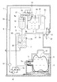
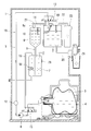
- Sectional drawing which shows the state at the time of normal operation of the water server of embodiment of this invention Sectional drawing which shows the state at the time of sterilization driving
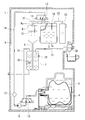
- operation of the water server of FIG. Sectional drawing which shows the state which is pouring low temperature drinking water from the cold water tank shown in FIG.
- Sectional drawing which shows the state which is pouring hot drinking water from the hot water tank shown in FIG.
- Sectional drawing of the container holder vicinity which shows the state which pulled out the container holder shown in FIG. 1 from a housing
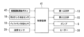
- the block diagram which shows the control apparatus of the water server of FIG.
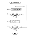
- the flowchart which shows the heater control of the hot water tank by the control apparatus shown in FIG. Flow chart showing intermittent pump drive control during sterilization operation by the control device shown in FIG.
- FIG. 1 shows a water server according to an embodiment of the present invention.
- the water server includes a housing 1, a cold water tank 2 for storing low-temperature drinking water for pouring out of the housing 1, and an exchangeable type filled with drinking water for replenishing the cold water tank 2.
- a hot water tank 7 for storing hot drinking water for pouring out of the housing 1, a buffer tank 8 disposed above the hot water tank 7, and hot water communicating between the buffer tank 8 and the hot water tank 7.
- a tank water supply pipe 9 is a tank water supply pipe 9.
- a joint portion 5 a that is detachably connected to the water outlet 11 of the raw water container 3 is provided at the upstream end of the raw water pumping tube 5.
- the downstream end of the raw water pumping pipe 5 is connected to the cold water tank 2.
- the raw water pumping pipe 5 is provided so as to change the direction upward after extending downward from the joint part 5a so as to pass through a position lower than the joint part 5a.
- the pump 6 is arrange
- the pump 6 transfers the drinking water in the raw water pumping pipe 5 from the raw water container 3 side to the cold water tank 2 side, and pumps drinking water from the raw water container 3 through the raw water pumping pipe 5.
- a diaphragm pump can be used as the pump 6.
- the diaphragm pump has only a diaphragm (not shown) that reciprocates, a pump chamber whose volume is increased or decreased by the reciprocation of the diaphragm, an intake port and a discharge port provided in the pump chamber, and a flow in a direction flowing into the pump chamber. It has a suction side check valve provided at the suction port so as to allow, and a discharge side check valve provided at the discharge port so as to allow only the flow in the direction of flowing out from the pump chamber.
- the volume of the pump chamber increases, drinking water is sucked from the suction port, and when the volume of the pump chamber decreases due to the backward movement of the diaphragm, the drinking water is discharged from the discharge port.
- the gear pump includes a casing (not shown), a pair of meshing gears housed in the casing, and a suction chamber and a discharge chamber in the casing defined by meshing portions of the pair of gears.
- the drinking water confined between the tooth gap and the inner surface of the casing is transferred from the suction chamber side to the discharge chamber side by rotation of the gear.
- a flow sensor 12 is provided on the discharge side of the pump 6 of the raw water pumping pipe 5.
- the flow sensor 12 detects the state when the flow of the drinking water in the raw water draw-out pipe 5 disappears when the pump 6 is driven.
- a container replacement lamp (not shown) arranged in front of the housing 1 is turned on to inform the user that it is time to replace the raw water container 3.
- a first three-way valve 13 is provided in a portion of the raw water pumping pipe 5 between the pump 6 and the cold water tank 2 (preferably the end of the raw water pumping pipe 5 on the cold water tank 2 side).
- the first three-way valve 13 is disposed at a position away from the cold water tank 2, but the first three-way valve 13 may be directly connected to the cold water tank 2.
- a buffer tank water supply pipe 14 that communicates between the first three-way valve 13 and the buffer tank 8 is connected to the first three-way valve 13. The end of the buffer tank water supply pipe 14 on the buffer tank 8 side is connected to the upper surface 8 a of the buffer tank 8.
- the first three-way valve 13 communicates between the pump 6 and the cold water tank 2 and blocks between the pump 6 and the buffer tank 8 (see FIG. 1), and between the pump 6 and the cold water tank 2. And the flow path can be switched between the buffer side connection position (see FIG. 2) that communicates between the pump 6 and the buffer tank 8.
- the first three-way valve 13 employs an electromagnetic valve that switches from the chilled water side connection position to the buffer side connection position when energized, and switches from the buffer side connection position to the chilled water side connection position when power is released. Yes.
- a second three-way valve 15 is provided in a portion of the raw water pumping pipe 5 between the pump 6 and the raw water container 3 (preferably the end of the raw water pumping pipe 5 on the raw water container 3 side).
- the second three-way valve 15 is disposed at a position away from the joint portion 5a, but the second three-way valve 15 may be directly connected to the joint portion 5a.
- the second three-way valve 15 is connected to a circulation pipe 16 that communicates between the second three-way valve 15 and the hot water tank 7.
- the end of the circulation pipe 16 on the warm water tank 7 side is connected to the upper surface 7 a of the warm water tank 7.
- the second three-way valve 15 communicates between the pump 6 and the raw water container 3 and disconnects between the pump 6 and the hot water tank 7 (see FIG. 1), and between the pump 6 and the raw water container 3. And the flow path can be switched between a hot water side connection position (see FIG. 2) that communicates between the pump 6 and the hot water tank 7.
- the second three-way valve 15 switches from the raw water side connection position to the hot water side connection position by energizing, and releases the energization from the hot water side connection position to the raw water side.
- a solenoid valve that switches to the connection position is used.
- the circulation path 19 includes, in order from the hot water tank 7, a circulation pipe 16, a second three-way valve 15, a portion between the first three-way valve 13 and the second three-way valve 15 of the raw water pumping pipe 5, A three-way valve 13, a buffer tank water supply pipe 14, a buffer tank 8, and a hot water tank water supply pipe 9 are provided, and a pump 6 is disposed in the middle of the circulation path 19.
- the cold water tank 2 contains air and drinking water in two upper and lower layers.
- a cooling device 17 for cooling the drinking water stored in the cold water tank 2 is attached to the cold water tank 2.
- the cooling device 17 is arrange
- the cold water tank 2 is provided with a water level sensor 18 for detecting the level of drinking water accumulated in the cold water tank 2.
- a water level sensor 18 for detecting the level of drinking water accumulated in the cold water tank 2.
- a cold water pouring pipe 20 for pouring low temperature drinking water in the cold water tank 2 to the outside is connected to the bottom surface of the cold water tank 2.
- the cold water pouring pipe 20 is provided with a cold water cock 21 that can be operated from the outside of the housing 1, and by opening the cold water cock 21, low-temperature drinking water can be poured into a cup or the like from the cold water tank 2. ing.
- the capacity of drinking water in the cold water tank 2 is smaller than the capacity of the raw water container 3 and is about 2 to 4 liters.
- the air sterilization chamber 23 is connected to the cold water tank 2 through an air introduction path 22.
- the air sterilization chamber 23 includes a hollow case 25 in which an air intake 24 is formed, and an ozone generator 26 provided in the case 25.
- the ozone generator 26 for example, a low-pressure mercury lamp that irradiates oxygen in the air with ultraviolet rays to change the oxygen into ozone, or an alternating voltage is applied between a pair of opposed electrodes covered with an insulator, between the electrodes.
- a silent discharge device that changes oxygen into ozone can be used.
- the air sterilization chamber 23 is always in a state where ozone is accumulated in the case 25 by energizing the ozone generator 26 at regular intervals to generate ozone.
- the air introduction path 22 introduces air into the cold water tank 2 according to a drop in the water level in the cold water tank 2 to keep the inside of the cold water tank 2 at atmospheric pressure. At this time, since the air introduced into the cold water tank 2 passes through the air sterilization chamber 23 and is sterilized with ozone, the air in the cold water tank 2 is kept clean.
- the buffer tank 8 contains air and drinking water in upper and lower layers.
- a vent pipe 27 is connected to the upper surface 8 a of the buffer tank 8.
- the ventilation pipe 27 keeps the inside of the buffer tank 8 at atmospheric pressure by communicating between the air layer in the buffer tank 8 and the air layer in the cold water tank 2.
- the buffer tank 8 is provided with a water level sensor 10 for detecting the level of drinking water accumulated in the buffer tank 8.
- a water level sensor 10 for detecting the level of drinking water accumulated in the buffer tank 8.
- the capacity of the drinking water in the buffer tank 8 is smaller than that of the hot water tank 7 and is about 0.2 to 0.5 liter. As will be described later, the drinking water in the buffer tank 8 has a role to push out the drinking water in the hot water tank 7 when the hot drinking water in the hot water tank 7 is poured out. Therefore, it is preferable that the buffer tank 8 has a vertically elongated shape (for example, a cylindrical shape whose height is larger than the diameter). In this way, even if the capacity of the drinking water in the buffer tank 8 is small, a relatively high water pressure is generated in the lower part of the buffer tank 8, so that a force for pushing out the drinking water in the hot water tank 7 is effectively obtained. It becomes possible.
- the buffer tank 8 is disposed so that the position of the water surface in the buffer tank 8 is the same as or lower than the water surface in the cold water tank 2.
- the buffer tank 8 may be arranged so that the position is higher than the water surface in the cold water tank 2. In this way, the difference in height between the buffer tank 8 and the hot water tank 7 becomes large, so that it is possible to effectively obtain a force for pushing the drinking water in the hot water tank 7 to the outside.
- the bottom surface 8b of the buffer tank 8 is formed in a conical shape that gradually decreases toward the center, and a hot water tank water supply pipe 9 is connected to the center of the bottom surface 8b.
- the hot water tank water supply pipe 9 is connected to a hot water tank 7 disposed below the buffer tank 8.
- the hot water tank 7 is completely filled with drinking water.
- a temperature sensor 29 that detects the temperature of drinking water in the hot water tank 7 and a heater 30 that heats the drinking water in the hot water tank 7 are attached to the hot water tank 7.
- the heater 30 is switched ON / OFF according to the temperature detected by the temperature sensor 29, and the drinking water in the hot water tank 7 is kept at a high temperature (about 90 ° C.).
- a sheath heater is employed as the heater 30 is shown, but a band heater can also be employed.
- the sheath heater contains a heating wire that generates heat when energized in a metal pipe, and is attached so as to penetrate the wall surface of the hot water tank 7 and extend inside the hot water tank 7.
- the band heater is a cylindrical heating element in which a heating wire that generates heat when energized is embedded, and is attached in close contact with the outer periphery of the hot water tank 7.
- a hot water pouring pipe 31 for pouring hot drinking water accumulated in the upper part of the hot water tank 7 to the outside.
- the hot water pouring pipe 31 is provided with a hot water cock 32 that can be operated from the outside of the housing 1. By opening the hot water cock 32, hot drinking water can be poured from the hot water tank 7 into a cup or the like. ing.
- the drinking water in the buffer tank 8 is introduced by its own weight through the hot water tank water supply pipe 9 into the hot water tank 7, and the hot water tank 7 is always kept in a full water state.
- the capacity of the drinking water in the hot water tank 7 is about 1 to 2 liters.
- a drain pipe 35 extending to the outside of the housing 1 is connected to the bottom surface of the hot water tank 7.
- the outlet of the drain pipe 35 is closed with a plug 36.
- An opening / closing valve may be provided instead of the plug 36.
- the raw water container 3 is provided with a hollow cylindrical body part 37, a bottom part 38 provided at one end of the body part 37, and a shoulder part 39 at the other end of the body part 37.
- the water outlet 11 is provided in the neck 40.
- natural water container 3 is formed with the softness
- the raw water container 3 is formed by blow molding of polyethylene terephthalate resin (PET).
- PET polyethylene terephthalate resin
- the capacity of the raw water container 3 is about 10 to 20 liters when it is full.
- bag-in-box As the raw water container 3, a bag made of a resin film in which a connector having a water outlet 11 is bonded by heat welding or the like (so-called bag-in-box) may be employed.
- the container holder 4 is placed horizontally between the housing position (the position shown in FIG. 1) where the raw water container 3 is housed in the housing 1 and the drawing position (the position shown in FIG. 5) from which the raw water container 3 comes out. It is supported movably. As shown in FIG. 5, the joint portion 5a is disconnected from the water outlet 11 of the raw water container 3 when the container holder 4 is moved to the drawing position, and the container holder 4 is moved to the accommodation position as shown in FIG. It is fixed in the housing 1 so as to be connected to the water outlet 11 of the raw water container 3 when it is caused.
- a silicon tube can be used as the raw water pumping pipe 5 (excluding the joint portion 5a), but since silicon has oxygen permeability, the raw water is pumped by oxygen in the air that permeates silicon. There is a problem that germs can easily propagate in the discharge pipe 5. Therefore, the raw water pumping pipe 5 can be a metal pipe (for example, a stainless steel pipe or a copper pipe). If it does in this way, it will become possible to prevent that air permeate
- the heater 30, the pump 6, the first three-way valve 13, and the second three-way valve 15 are controlled by a control device 41 shown in FIG.
- the control device 41 keeps the water level of the cold water tank 2 and the water level of the buffer tank 8 within a certain range, and also keeps the temperature within the hot water tank 7 within a certain range.
- the three-way valve 13 and the second three-way valve 15 are controlled.
- the circulation path 19 that is, the portion between the first three-way valve 13 and the second three-way valve 15 of the hot water tank 7, the circulation pipe 16, the second three-way valve 15, and the raw water pumping pipe 5).
- the first three-way valve 13, the buffer tank water supply pipe 14, the buffer tank 8, and the hot water tank water supply pipe 9) are sterilized at high temperature with hot drinking water in the hot water tank 7, and the heater 30, the pump 6, and the first The three-way valve 13 and the second three-way valve 15 are controlled.
- the control device 41 includes a signal indicating the presence / absence of a button operation by the user from the sterilization operation start button 42, a signal indicating the level of drinking water accumulated in the cold water tank 2 from the water level sensor 18, and a water level sensor A signal indicating the level of drinking water accumulated in the buffer tank 8 is input from 10, and a signal indicating the temperature of drinking water in the hot water tank 7 is input from the temperature sensor 29. Further, from the control device 41, a control signal for driving the pump 6, a control signal for switching the heater 30 on and off, a control signal for switching the flow path of the first three-way valve 13, and the second three-way valve 15 A control signal for switching the flow path is output.
- the sterilization operation start button 42 is a button for instructing the start of the sterilization operation.
- the sterilization operation start button 42 When the user operates the sterilization operation start button 42, the first sterilization operation is started. The second and subsequent sterilization operations are automatically performed each time one day elapses since the elapsed time from the time when the first sterilization operation was performed by a timer built in the control device 41 is counted. Further, when the sterilization operation start button 42 is not operated, the sterilization operation can be automatically performed every day after the water server is turned on.
- the sterilization operation start button 42 is disposed on the front surface of the housing 1.
- the water level of the cold water tank 2 and the buffer tank 8 is controlled. That is, as shown in FIG. 3, when the water level in the cold water tank 2 falls below a preset lower limit water level, the first three-way valve 13 is switched to the cold water side connection position, and the pump 6 is driven in that state. Thus, drinking water is pumped from the raw water container 3 to the cold water tank 2, and then the pump 6 is stopped when the water level in the cold water tank 2 reaches a preset upper limit water level. As shown in FIG. 4, when the water level in the buffer tank 8 falls below a preset lower limit water level, the first three-way valve 13 is switched to the buffer side connection position, and the pump 6 is driven in that state. Thus, the drinking water is pumped from the raw water container 3 to the buffer tank 8, and then the pump 6 is stopped when the water level in the buffer tank 8 reaches a preset upper limit water level.
- the heater control of the hot water tank 7 is performed in parallel with the above water level control. This heater control is performed, for example, according to the routine shown in FIG.
- a preset lower limit temperature L for example, 85 ° C.
- the heater 30 is turned on to raise the temperature in the hot water tank 7 (steps S 10 and S 11 ).
- a preset upper limit temperature H for example, 90 ° C.
- the first three-way valve 13 is switched to the buffer side connection position and the second three-way valve 15 is switched to the circulation side connection position to form the circulation path 19, and this state is maintained.
- the heater control of the hot water tank 7 and the pump intermittent drive control for intermittently driving the pump 6 according to the temperature change of the hot water tank 7 are performed in parallel.
- This pump intermittent drive control is performed, for example, according to a routine shown in FIG.
- a preset high temperature lower limit temperature L of the heater control in the figure
- the temperature in the hot water tank 7 is increased by the heater control and reaches a predetermined high temperature. until performs the first operation for holding the pump 6 stopped (step S 20, S 21).
- the predetermined high temperature is set to a temperature that is at least higher than the sterilizable temperature (65 ° C.) (however, a temperature equal to or lower than the upper limit temperature H of the heater control).
- the sterilizable temperature 65 ° C.
- H sterilizable temperature
- the first operation (steps S 20 and S 21 ) of the pump 6 can be controlled by using ON and OFF of the thermostat. It becomes.
- the predetermined high temperature the same temperature as the upper limit temperature H (for example, 90 ° C.) of the heater control can be adopted.
- step S 22 the second operation for continuously driving the pump 6 for a predetermined time T is performed.
- step S 22 the drinking water in the circulation path 19 (here, in particular, the buffer tank 8) is introduced into the hot water tank 7, so that the temperature in the hot water tank 7 is lowered.
- the heater 30 is turned on.
- the predetermined time T is set to a time that is the same as or shorter than the time that the pump 6 sends out drinking water corresponding to the capacity of the hot water tank 7. For example, a capacity of 1.2 liters of drinking water of the hot water tank 7, if the amount of drinking water pump 6 feeds per minute is 1 liter predetermined time for continuous driving of the pump 6 at step S 22 T is set to a time (for example, 1 minute) that is the same as or shorter than the time (1 minute 12 seconds) at which the pump 6 delivers 1.2 liters of drinking water.
- the predetermined time T is set to be the same as or longer than the time when the pump 6 sends out drinking water corresponding to the capacity of the buffer tank 8.
- the capacity of the drinking water in the buffer tank 8 is 0.3 liters when the amount of drinking water pump 6 feeds per minute is 1 liter
- predetermined time for continuous driving of the pump 6 at step S 22 T is set to a time (for example, 1 minute) that is equal to or longer than the time (18 seconds) at which the pump 6 delivers 0.3 liters of drinking water.
- step S 22 After performing the second operation (step S 22 ), it is determined whether or not the temperature in the hot water tank 7 at that time is equal to or higher than the lower limit temperature L of the heater control (step S 23 ). When it is determined that the value is low, the process returns to the first operation (steps S 20 and S 21 ). Thereafter, the first operation (steps S 20 and S 21 ) and the second operation (step S 22 ) are alternately repeated.
- step S 22 After performing the second operation (step S 22 ), when it is determined that the temperature in the hot water tank 7 at that time is equal to or higher than the sterilization temperature (lower limit temperature L of the heater control in the figure) (step S 23 ). Since it is considered that the temperature of the drinking water in the circulation path 19 has reached the sterilization temperature as a whole, the repetition of the first operation and the second operation of the pump intermittent drive control is ended.
- the sterilization temperature is set to a temperature higher than the sterilizable temperature (65 ° C.) and lower than the upper limit temperature H of the heater control, and as such a temperature, the lower limit temperature L of the heater control (for example, 85 The same temperature can be employed.
- the pump 6 is continuously driven, and in parallel with this, the heater control of the hot water tank 7 is performed, so that the hot drinking water that has reached the sterilization temperature.
- the circulation path 19 can be surely sterilized.
- a driving method in which the fourth operation held in the state is alternately repeated can be employed. Thereby, the total rotation speed of the pump 6 required to circulate the hot drinking water that has reached the sterilization temperature in the circulation path 19 can be suppressed.
- control unit 41 the rotational speed of the pump 6 when the rotational speed of the pump 6 at the time of driving the pump 6 during sterilization operation (or step S 22 of the pump intermittent drive control), to drive the pump 6 during normal operation
- the pump 6 is driven at a lower speed.
- the above-described water server can sterilize the circulation path 19 including the raw water pumping pipe 5 and the buffer tank 8 that are in contact with the drinking water drawn out from the raw water container 3 and having a temperature close to normal temperature with the hot drinking water in the hot water tank 7. Because it can, it is excellent in hygiene.
- the water server holds the pump 6 in a stopped state when the temperature in the hot water tank 7 does not rise to a predetermined high temperature (here, the lower limit temperature L) during the sterilization operation,
- a predetermined high temperature here, the lower limit temperature L
- the pump 6 is driven and high-temperature drinking water is sent out from the hot water tank 7, so that the temperature of the drinking water circulating in the circulation path 19 as a whole becomes the sterilization temperature.
- the total number of rotations of the pump 6 required to raise is small. Therefore, the total number of rotations of the pump 6 required for one sterilization operation can be suppressed, and the life of the pump 6 is ensured even when the sterilization operation is performed at a high frequency (for example, about once a day). Is possible. As a result, it is possible to improve the hygiene of the water server.
- the water server has a predetermined time T for continuously driving the pump 6 in the second operation of the intermittent pump drive control (step S 22 ), and a time for the pump 6 to send out drinking water corresponding to the capacity of the hot water tank 7. Since the same or shorter time is set, it is possible to effectively extend the life of the pump 6. That is, when the pump 6 sends out the drinking water corresponding to the capacity of the hot water tank 7, it is considered that the hot drinking water in the hot water tank 7 is almost replaced at that time, and the pump 6 is continuously used for a longer time. Driving leads to unnecessary consumption of the pump 6.
- the predetermined time T during which the pump 6 is continuously driven in the second operation is equal to or longer than the time during which the pump 6 delivers drinking water corresponding to the capacity of the hot water tank 7.
- the water server has a predetermined time T for continuously driving the pump 6 in the second operation of the intermittent pump drive control (step S 22 ), and a time for the pump 6 to send out drinking water corresponding to the capacity of the buffer tank 8. Since the time is set to be the same or longer, the drinking water in the buffer tank 8 can be replaced with hot drinking water each time the pump 6 performs continuous driving once. Can be effectively sterilized.
- the water server having the circulation path 19 that does not pass through the cold water tank 2 is described as an example of the circulation path 19 through which the drinking water circulates through the hot water tank 7 during the sterilization operation.
- the present invention can also be applied to a water server having a circulation path passing through the cold water tank 2 (that is, a water server of the type that sterilizes the cold water tank 2 with hot drinking water in the hot water tank 7).
Landscapes
- Physics & Mathematics (AREA)
- Chemical & Material Sciences (AREA)
- Analytical Chemistry (AREA)
- Fluid Mechanics (AREA)
- Devices For Dispensing Beverages (AREA)
- Engineering & Computer Science (AREA)
- Mechanical Engineering (AREA)
Abstract
Description
外部に注出するための高温の飲料水を収容する温水タンクと、
その温水タンク内の飲料水を加熱するヒーターと、
前記温水タンクを経由して飲料水が循環できるように設けられた循環経路と、
その循環経路の途中に設けられたポンプと、
前記循環経路を前記温水タンク内の高温の飲料水で高温殺菌するように前記ヒーターとポンプとを制御する制御装置とを有し、
その制御装置は、前記循環経路の殺菌運転時に、
前記温水タンク内の温度が予め設定された下限温度よりも低いときに前記ヒーターをONにし、前記温水タンク内の温度が予め設定された上限温度に達したときに前記ヒーターをOFFにするヒーター制御と、
前記温水タンク内の温度が予め設定された所定の高温よりも低いときに前記ポンプを停止状態に保持する第1動作と、前記温水タンク内の温度が前記ヒーター制御で上昇して前記所定の高温に達したときに、前記ポンプを所定時間だけ連続して駆動する第2動作とを交互に繰り返すポンプ間欠駆動制御と、
を並行して行なう。
7 温水タンク
19 循環経路
30 ヒーター
41 制御装置
Claims (2)
- 外部に注出するための高温の飲料水を収容する温水タンク(7)と、
その温水タンク(7)内の飲料水を加熱するヒーター(30)と、
前記温水タンク(7)を経由して飲料水が循環できるように設けられた循環経路(19)と、
その循環経路(19)の途中に設けられたポンプ(6)と、
前記循環経路(19)を前記温水タンク(7)内の高温の飲料水で高温殺菌するように前記ヒーター(30)とポンプ(6)とを制御する制御装置(41)とを有し、
その制御装置(41)は、前記循環経路(19)の殺菌運転時に、
前記温水タンク(7)内の温度が予め設定された下限温度(L)よりも低いときに前記ヒーター(30)をONにし、前記温水タンク(7)内の温度が予め設定された上限温度(H)に達したときに前記ヒーター(30)をOFFにするヒーター制御と、
前記温水タンク(7)内の温度が予め設定された所定の高温(L)よりも低いときに前記ポンプ(6)を停止状態に保持する第1動作(ステップS20、S21)と、前記温水タンク(7)内の温度が前記ヒーター制御で上昇して前記所定の高温(L)に達したときに、前記ポンプ(6)を所定時間(T)だけ連続して駆動する第2動作(ステップS22)とを交互に繰り返すポンプ間欠駆動制御と、
を並行して行なうウォーターサーバー。 - 前記第2動作(ステップS22)で、前記ポンプ(6)の連続駆動を行なう所定時間(T)を、ポンプ(6)が前記温水タンク(7)の容量に相当する飲料水を送り出す時間と同じか、それよりも短い時間に設定した請求項1に記載のウォーターサーバー。
Priority Applications (4)
| Application Number | Priority Date | Filing Date | Title |
|---|---|---|---|
| CN201380073937.5A CN105026302B (zh) | 2013-03-05 | 2013-12-16 | 饮水机 |
| US14/771,815 US20160016777A1 (en) | 2013-03-05 | 2013-12-16 | Water dispenser |
| KR1020157027529A KR102092434B1 (ko) | 2013-03-05 | 2013-12-16 | 워터 서버 |
| EP13877103.5A EP2966029A4 (en) | 2013-03-05 | 2013-12-16 | WATER DISPENSER |
Applications Claiming Priority (2)
| Application Number | Priority Date | Filing Date | Title |
|---|---|---|---|
| JP2013042976A JP5806247B2 (ja) | 2013-03-05 | 2013-03-05 | ウォーターサーバー |
| JP2013-042976 | 2013-03-05 |
Publications (1)
| Publication Number | Publication Date |
|---|---|
| WO2014136350A1 true WO2014136350A1 (ja) | 2014-09-12 |
Family
ID=51490891
Family Applications (1)
| Application Number | Title | Priority Date | Filing Date |
|---|---|---|---|
| PCT/JP2013/083569 Ceased WO2014136350A1 (ja) | 2013-03-05 | 2013-12-16 | ウォーターサーバー |
Country Status (7)
| Country | Link |
|---|---|
| US (1) | US20160016777A1 (ja) |
| EP (1) | EP2966029A4 (ja) |
| JP (1) | JP5806247B2 (ja) |
| KR (1) | KR102092434B1 (ja) |
| CN (1) | CN105026302B (ja) |
| TW (1) | TWI624623B (ja) |
| WO (1) | WO2014136350A1 (ja) |
Families Citing this family (12)
| Publication number | Priority date | Publication date | Assignee | Title |
|---|---|---|---|---|
| JP2016199300A (ja) * | 2015-04-13 | 2016-12-01 | 株式会社ウォーターダイレクト | 飲料サーバ |
| KR101772163B1 (ko) * | 2015-12-11 | 2017-09-12 | 홍종국 | 급속 고온멸균 기능이 있는 직수냉온수기 |
| KR101772162B1 (ko) * | 2015-12-11 | 2017-08-28 | 홍종국 | 고온멸균 기능이 있는 직수냉온수기 |
| KR102799610B1 (ko) * | 2016-12-09 | 2025-04-23 | 엘지전자 주식회사 | 음용수 공급 장치 및 그 제어 방법 |
| CN109247783A (zh) * | 2017-03-25 | 2019-01-22 | 李明明 | 一种具有摄像功能的饮料容器载体 |
| CN108001802A (zh) * | 2017-03-25 | 2018-05-08 | 聂世林 | 饮料容器载体的使用方法 |
| JP6894626B2 (ja) * | 2017-07-14 | 2021-06-30 | パーパス株式会社 | 補水制御方法およびウォーターサーバー |
| JP6954171B2 (ja) * | 2018-02-16 | 2021-10-27 | 富士電機株式会社 | 飲料供給装置 |
| CN115105191A (zh) * | 2018-04-27 | 2022-09-27 | 雷森斯医疗有限公司 | 冷却装置和冷却方法 |
| JP7448260B2 (ja) * | 2020-11-13 | 2024-03-12 | 株式会社一蘭 | 調理装置 |
| US12122659B2 (en) | 2021-08-31 | 2024-10-22 | Versabev, Inc. | Scalable modular system and method for valve control and selectively dispensing beverages |
| KR20250004730A (ko) * | 2022-04-07 | 2025-01-08 | 퀜치 유에스에이 인코포레이티드 | 물 디스펜서용 세척 모드 |
Citations (5)
| Publication number | Priority date | Publication date | Assignee | Title |
|---|---|---|---|---|
| JPH0648488A (ja) * | 1992-07-24 | 1994-02-22 | Suntory Ltd | 飲料水のディスペンサ |
| JPH11190577A (ja) * | 1997-12-26 | 1999-07-13 | Fuji Electric Co Ltd | 飲料水のディスペンサ |
| JP2004206301A (ja) * | 2002-12-24 | 2004-07-22 | Benten:Kk | 冷温水機の殺菌装置 |
| JP2009046150A (ja) * | 2007-08-20 | 2009-03-05 | Takagi Ind Co Ltd | 飲料水供給装置 |
| JP2011102154A (ja) * | 2011-02-18 | 2011-05-26 | Takagi Ind Co Ltd | 飲料水供給装置 |
Family Cites Families (6)
| Publication number | Priority date | Publication date | Assignee | Title |
|---|---|---|---|---|
| US1920013A (en) * | 1932-08-10 | 1933-07-25 | Globe Machine & Stamping Co | Beverage water heater |
| JP4549068B2 (ja) * | 2004-01-19 | 2010-09-22 | サントリーホールディングス株式会社 | 飲料水のディスペンサ |
| CN201029781Y (zh) * | 2007-06-05 | 2008-03-05 | 黄瑞中 | 高温水消毒饮水机 |
| US20100252585A1 (en) * | 2009-04-01 | 2010-10-07 | Yui George M | Water probe for bottom loading water cooler |
| WO2011104753A1 (ja) * | 2010-02-24 | 2011-09-01 | 高木産業株式会社 | 飲料水供給装置 |
| IL217213A (en) * | 2011-12-26 | 2014-06-30 | Yehuda Forte | Water facility that includes a cleaning mechanism |
-
2013
- 2013-03-05 JP JP2013042976A patent/JP5806247B2/ja active Active
- 2013-12-16 EP EP13877103.5A patent/EP2966029A4/en not_active Withdrawn
- 2013-12-16 US US14/771,815 patent/US20160016777A1/en not_active Abandoned
- 2013-12-16 KR KR1020157027529A patent/KR102092434B1/ko active Active
- 2013-12-16 WO PCT/JP2013/083569 patent/WO2014136350A1/ja not_active Ceased
- 2013-12-16 CN CN201380073937.5A patent/CN105026302B/zh active Active
-
2014
- 2014-02-25 TW TW103106333A patent/TWI624623B/zh active
Patent Citations (6)
| Publication number | Priority date | Publication date | Assignee | Title |
|---|---|---|---|---|
| JPH0648488A (ja) * | 1992-07-24 | 1994-02-22 | Suntory Ltd | 飲料水のディスペンサ |
| JP3387526B2 (ja) | 1992-07-24 | 2003-03-17 | サントリー株式会社 | 飲料水のディスペンサ |
| JPH11190577A (ja) * | 1997-12-26 | 1999-07-13 | Fuji Electric Co Ltd | 飲料水のディスペンサ |
| JP2004206301A (ja) * | 2002-12-24 | 2004-07-22 | Benten:Kk | 冷温水機の殺菌装置 |
| JP2009046150A (ja) * | 2007-08-20 | 2009-03-05 | Takagi Ind Co Ltd | 飲料水供給装置 |
| JP2011102154A (ja) * | 2011-02-18 | 2011-05-26 | Takagi Ind Co Ltd | 飲料水供給装置 |
Non-Patent Citations (1)
| Title |
|---|
| See also references of EP2966029A4 * |
Also Published As
| Publication number | Publication date |
|---|---|
| CN105026302A (zh) | 2015-11-04 |
| JP5806247B2 (ja) | 2015-11-10 |
| TWI624623B (zh) | 2018-05-21 |
| KR102092434B1 (ko) | 2020-03-23 |
| TW201441550A (zh) | 2014-11-01 |
| KR20150125713A (ko) | 2015-11-09 |
| EP2966029A4 (en) | 2016-07-27 |
| JP2014169121A (ja) | 2014-09-18 |
| CN105026302B (zh) | 2017-08-22 |
| US20160016777A1 (en) | 2016-01-21 |
| EP2966029A1 (en) | 2016-01-13 |
Similar Documents
| Publication | Publication Date | Title |
|---|---|---|
| JP5806247B2 (ja) | ウォーターサーバー | |
| JP5529312B1 (ja) | ウォーターサーバー | |
| JP5520405B1 (ja) | ウォーターサーバー | |
| JP5529314B1 (ja) | ウォーターサーバー | |
| JP5571218B1 (ja) | ウォーターサーバー | |
| JP5647636B2 (ja) | ウォーターサーバー | |
| JP5806432B2 (ja) | ウォーターサーバー | |
| JP5806433B2 (ja) | ウォーターサーバー |
Legal Events
| Date | Code | Title | Description |
|---|---|---|---|
| WWE | Wipo information: entry into national phase |
Ref document number: 201380073937.5 Country of ref document: CN |
|
| 121 | Ep: the epo has been informed by wipo that ep was designated in this application |
Ref document number: 13877103 Country of ref document: EP Kind code of ref document: A1 |
|
| WWE | Wipo information: entry into national phase |
Ref document number: 14771815 Country of ref document: US |
|
| NENP | Non-entry into the national phase |
Ref country code: DE |
|
| REEP | Request for entry into the european phase |
Ref document number: 2013877103 Country of ref document: EP |
|
| WWE | Wipo information: entry into national phase |
Ref document number: 2013877103 Country of ref document: EP |
|
| ENP | Entry into the national phase |
Ref document number: 20157027529 Country of ref document: KR Kind code of ref document: A |