WO2014136411A1 - 電流測定装置 - Google Patents
電流測定装置 Download PDFInfo
- Publication number
- WO2014136411A1 WO2014136411A1 PCT/JP2014/001080 JP2014001080W WO2014136411A1 WO 2014136411 A1 WO2014136411 A1 WO 2014136411A1 JP 2014001080 W JP2014001080 W JP 2014001080W WO 2014136411 A1 WO2014136411 A1 WO 2014136411A1
- Authority
- WO
- WIPO (PCT)
- Prior art keywords
- quarter
- current measuring
- measuring device
- optical fiber
- faraday
- Prior art date
- Legal status (The legal status is an assumption and is not a legal conclusion. Google has not performed a legal analysis and makes no representation as to the accuracy of the status listed.)
- Ceased
Links
Images














Classifications
-
- G—PHYSICS
- G01—MEASURING; TESTING
- G01R—MEASURING ELECTRIC VARIABLES; MEASURING MAGNETIC VARIABLES
- G01R15/00—Details of measuring arrangements of the types provided for in groups G01R17/00 - G01R29/00, G01R33/00 - G01R33/26 or G01R35/00
- G01R15/14—Adaptations providing voltage or current isolation, e.g. for high-voltage or high-current networks
- G01R15/24—Adaptations providing voltage or current isolation, e.g. for high-voltage or high-current networks using light-modulating devices
- G01R15/245—Adaptations providing voltage or current isolation, e.g. for high-voltage or high-current networks using light-modulating devices using magneto-optical modulators, e.g. based on the Faraday or Cotton-Mouton effect
- G01R15/246—Adaptations providing voltage or current isolation, e.g. for high-voltage or high-current networks using light-modulating devices using magneto-optical modulators, e.g. based on the Faraday or Cotton-Mouton effect based on the Faraday, i.e. linear magneto-optic, effect
-
- G—PHYSICS
- G01—MEASURING; TESTING
- G01R—MEASURING ELECTRIC VARIABLES; MEASURING MAGNETIC VARIABLES
- G01R19/00—Arrangements for measuring currents or voltages or for indicating presence or sign thereof
- G01R19/0092—Measuring current only
Definitions
- the present invention relates to a current measuring device using the Faraday effect, and relates to a reflection type current measuring device that makes light incident from one end side of a sensor optical fiber and reflects the light at the other end side.
- Patent Document 1 discloses a reflection-type current measurement device that uses the Faraday effect in which the plane of polarization of light rotates by the action of a magnetic field.
- This current measuring device is a reflection type current measuring device in which a lead glass fiber is used as a sensor optical fiber and a mirror is disposed on the other end of the sensor optical fiber.
- the sensor optical fiber is installed around the conductor through which the current to be measured flows to detect the current to be measured, and the linearly polarized light incident from one end of the sensor optical fiber is reciprocated by the mirror while being reciprocated by the mirror.
- the basic configuration is to measure the Faraday rotation angle of linearly polarized light that rotates in the magnetic field of the measurement current.
- a Faraday rotator made of a ferromagnetic crystal such as YIG is provided.
- the Faraday rotation angle of the Faraday rotator used in the current measuring device has a characteristic (temperature characteristic) that depends on the ambient temperature, and the optical fiber for the sensor also has a ratio error due to the temperature dependence of the Verde constant and the Faraday rotation angle. Temperature characteristics exist. Therefore, not only compensation of the Faraday rotator but also compensation (reduction) of the temperature characteristic of the optical fiber for the sensor is necessary.
- the present inventor has a current in which the fluctuation range of the ratio error is suppressed within ⁇ 0.5% or ⁇ 0.2%. A measuring device was invented (see Patent Document 2).
- the current measuring device described in Patent Literature 2 includes a signal processing circuit including at least a sensor optical fiber, a polarization separator, a Faraday rotator, a light source, and a photoelectric conversion element, and constitutes a current measuring device.
- the optical fiber is installed around the outer circumference of the conductor through which the current to be measured flows. Further, by setting the Faraday rotation angle at the time of magnetic saturation of the Faraday rotator to 22.5 ° + ⁇ ° at a temperature of 23 ° C.
- the fluctuation range of the ratio error in the measured value of the output current to be measured is set within a range of ⁇ 0.5% or ⁇ 0.2% over a temperature range of ⁇ 20 ° C. to 80 ° C.
- the fluctuation range of the ratio error in the measured current value output from the signal processing circuit is within a range of ⁇ 0.5% or ⁇ 0.2%. It is suppressed to. Therefore, the temperature characteristic compensation of the ratio error in the measured value can be performed by the Faraday rotator, and the reliability of the current measuring device is improved, and the fluctuation range of the ratio error is ⁇ 0.5% or ⁇ 0.2%.
- the current measuring device that can be applied to the protective relay is realized.
- the optical fiber for the sensor has birefringence even in a straight state, and is further installed around the conductor. Therefore, the sensor optical fiber is deformed from a straight state. Due to the deformation accompanying the bending, a stress is generated in the sensor optical fiber, and the birefringence is further generated in the sensor optical fiber due to the stress. As a result, as the ratio error is reduced, two propagation modes having uncontrollable phases are output at the time of output from the sensor optical fiber. The inventor has found that it appears.
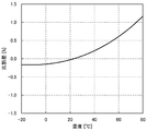
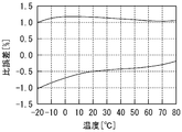
- the fluctuation range of the ratio error caused by the birefringence of the sensor optical fiber is as shown in FIG.
- the measured value of the current to be measured output from the current measuring device it appeared in the range of about ⁇ 1.0% to about 1.2% (in the temperature range of ⁇ 20 ° C. to 80 ° C., about ⁇ 0. 7% to about 1.2% range). Therefore, it is difficult to suppress the fluctuation range of the ratio error in the measured value of the measured current within the range of ⁇ 0.5% only by reducing the fluctuation range of the Faraday rotator's ratio error as described above. I found.
- the present invention has been made in view of the above circumstances, and it is possible to reliably keep the fluctuation range of the ratio error in the output within a range of ⁇ 0.5%, and to facilitate assembly. It is an object to provide a measuring device.
- the above-mentioned subject is achieved by the following present invention. That is, (1)
- the current measuring apparatus of the present invention includes at least a light incident / exit section, a sensor optical fiber, a Faraday rotator, a first quarter wavelength plate and a second quarter wavelength plate, and polarization separation.
- a signal processing circuit including a light source, a light source, and a photoelectric conversion element
- the light incident / exit section is configured by arranging two waveguides, In order from the light incident / exit section, a polarization separator, a first quarter-wave plate, a second quarter-wave plate, a Faraday rotator, and a sensor optical fiber are arranged, Further, the sensor optical fiber has birefringence, and is installed around the outer circumference of the conductor through which the current to be measured flows, and reflects one of the circularly polarized light and one end for entering two circularly polarized lights having different rotation directions.
- the second quarter wave plate is provided on one end side of the optical fiber for the sensor,
- the Faraday rotator is disposed between one end of the sensor optical fiber and the second quarter-wave plate,
- the light emitted from the light source is reflected at the other end so as to reciprocate between the polarization separator, the first quarter-wave plate, the second quarter-wave plate, the Faraday rotator, and the sensor optical fiber.
- a round-trip optical path is set, Two linearly polarized light is propagated in a reciprocating optical path between the first quarter-wave plate and the second quarter-wave plate, and between the first quarter-wave plate and the second quarter-wave plate.
- the phase difference between the two linearly polarized light in the round-trip optical path is compensated, Furthermore, the Faraday rotation angle at the time of magnetic saturation of the Faraday rotator is set to 22.5 ° + ⁇ ° at a temperature of 23 ° C., and the fluctuation range of the ratio error in the measured current value output from the signal processing circuit is ⁇ Set within the range of 0.5%, The crystal axis directions on the optical surfaces of the first quarter wavelength plate and the second quarter wavelength plate are set so as to be orthogonal or set in the same direction.
- the reciprocating optical path between the first quarter wave plate and the second quarter wave plate that propagates two linearly polarized lights is composed of a polarization plane holding fiber (PMF) or a crystal on the optical surface.
- PMF polarization plane holding fiber
- One embodiment of the current measuring device of the present invention is set so that the crystal axis direction on the optical surface of the polarization separator is orthogonal to the crystal axis direction on the optical surface of the first quarter-wave plate. Or set in the same direction.
- the crystal axis direction on the optical surface of the polarization separator, the crystal axis direction on the optical surface of the first quarter-wave plate, and the second The crystal axis direction on the optical surface of the quarter-wave plate is set in the same direction.
- the temperature range in which the fluctuation range is set within a range of ⁇ 0.5% is 100 ° C.
- the temperature range of 100 ° C. is preferably ⁇ 20 ° C. or higher and 80 ° C. or lower.
- the Faraday rotator has a temperature characteristic of a Faraday rotation angle at which the Faraday rotation angle at the time of magnetic saturation changes in a quadratic curve shape with a change in temperature. It is preferable.
- the Faraday rotator is preferably composed of two or more Faraday elements.
- the fluctuation range of the ratio error in the measured value of the measured current output from the signal processing circuit is set within a range of ⁇ 0.2%. Is preferred.
- the temperature range in which the fluctuation range is set within a range of ⁇ 0.2% is 100 ° C.
- the temperature range of 100 ° C. is preferably ⁇ 20 ° C. or more and 80 ° C. or less.
- the sensor optical fiber is preferably a lead glass fiber.
- the rotational angle of the Faraday rotator is changed from 22.5 ° to ⁇ ° at a temperature of 23 ° C.
- the linear error in the birefringence inherent in the sensor optical fiber is compensated, and two straight lines in the round-trip optical path between the first quarter-wave plate and the second quarter-wave plate
- the phase difference of polarization is also compensated. Accordingly, all phase differences other than the phase difference of the rotation angle of the Faraday rotator are compensated for, except for the phase difference ⁇ due to the Faraday effect inside the sensor optical fiber, and do not appear in the output of the current measuring device.
- the fluctuation range of the ratio error (about ⁇ 1.0% to about 1.2%) due to the birefringence of the sensor optical fiber is compensated, and the first quarter-wave plate and the second 1 Since the phase difference between the two linearly polarized lights in the round-trip optical path between the / 4 wavelength plates is also compensated, it is possible to reliably keep the fluctuation range of the ratio error in the output of the current measuring device within a range of ⁇ 0.5%. .
- phase difference ⁇ since all phase differences other than the phase difference of the rotation angle of the Faraday rotator are compensated except for the phase difference ⁇ , when the light propagates through the optical fiber of the current measuring device, the phase is changed due to disturbance. However, the output of the current measuring device is not affected. Accordingly, it is possible to stabilize the output characteristics of the current measuring device.
- the crystal axis directions on the optical surfaces of the first and second quarter-wave plates are set to be orthogonal or set in the same direction. Accordingly, when configuring a current measuring device using circularly polarized light, even if the number of constituent elements is increased by two quarter-wave plates, a fine angle adjustment operation in the direction of the crystal axes is not necessary. Accordingly, it is possible to simultaneously realize a high function of suppressing the ratio error fluctuation range within a range of ⁇ 0.5% and facilitating the assembly work of the constituent elements.
- the current measuring device of the present invention can be widely realized regardless of the type of sensor optical fiber, the yield of the current measuring device can be improved.
- the Faraday rotation angle at the time of magnetic saturation changes in a quadratic curve as the temperature rises.
- the fluctuation range of the ratio error in the measured current value output from the signal processing circuit is within a range of ⁇ 0.5% or ⁇ 0.2%.
- the current measuring device is used for applications that require temperature characteristics with a specific error within the range of ⁇ 0.2% (for example, watt-hour meters for measuring electricity charges). Can be used.
- the Faraday rotation angle of each Faraday element can be configured to be different from each other. Can be set to desired characteristics.
- the invention of claim 12 that is, the invention of (12)
- the measured value of the current to be measured output from the signal processing circuit It is possible to suppress the fluctuation range of the ratio error in the range of ⁇ 0.5% (or ⁇ 0.2%).
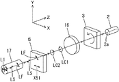
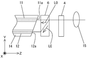
- FIG. 3 is a perspective view showing the arrangement of each component from the light incident / exit section to the polarization plane holding fiber and the polarization state of light in the forward path of the current measuring device of FIG. 2.
- FIG. 3 is a perspective view showing the arrangement of components from the polarization plane holding fiber to the sensor optical fiber and the polarization state of light in the forward path of the current measuring device of FIG. 2.
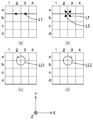
- FIG. 3 is an explanatory diagram of an end face of a polarization plane holding fiber showing a polarization preserving axis direction of the polarization plane holding fiber in FIG. 2 and a polarization state of incident light to the polarization plane holding fiber. It is explanatory drawing which shows the crystal-axis direction of the 2nd quarter wavelength plate in FIG. 2, and the polarization state of the propagation light to the 2nd quarter wavelength plate.
- FIG. 3 is an explanatory diagram showing a polarization state of propagating light emitted from a first optical fiber and reflected by the other end of the sensor optical fiber in the current measuring device of FIG. 2.
- FIG. 3 is a perspective view showing the arrangement of components from the polarization plane holding fiber to the sensor optical fiber and the polarization state of light in the return path of the current measuring device of FIG. 2.
- FIG. 3 is a perspective view showing the arrangement of components from the light incident / exit section to the polarization plane holding fiber and the polarization state of light in the return path of the current measuring device of FIG. 2.
- FIG. 3 is an explanatory diagram showing a polarization state of propagating light reflected from the other end of the sensor optical fiber and incident on the first and second optical fibers in the current measuring device of FIG. 2.
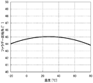
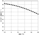
- FIG. It is a graph which shows typically the Faraday rotation angle temperature dependence at the time of changing in Faraday rotation angle in the temperature of 23 degreeC from 22.5 degrees only (alpha), and reciprocating.
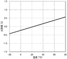
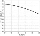
- the temperature characteristic graph of the ratio error in the measured value of the current under test outputted from the signal processing circuit It is a graph which shows typically the temperature characteristic of the specific error of the lead glass fiber used for the optical fiber for sensors. It is explanatory drawing which shows the structure of another form of FIG. It is a graph which shows typically the temperature characteristic of the Faraday rotation angle of the 1st Faraday element. It is a graph which shows typically the temperature characteristic of the Faraday rotation angle of the 2nd Faraday element.
- FIG. 20 is an example of a temperature characteristic graph of a ratio error of the current measuring device in the measured value of the current to be measured obtained from the Faraday rotation angle temperature dependency of FIG.
- FIG. 3 is a perspective view showing another form of a round-trip optical path between the first quarter-wave plate and the second quarter-wave plate in FIG. 2 and the optical path of light.
- the temperature characteristic graph of the ratio error in Example 1 of the current measuring device of the present invention The graph which shows an example of the temperature characteristic of the Faraday rotation angle of the Faraday element 27a in Example 2 of the electric current measuring apparatus of this invention.
- the temperature characteristic graph of the ratio error in Example 2 of the current measuring device of the present invention The temperature characteristic graph of the ratio error in Example 2 of the current measuring device of the present invention.
- the graph which shows the temperature characteristic of the Faraday rotation angle of the Faraday rotator in Example 3 of the current measuring device of the present invention The temperature characteristic graph of the ratio error in Example 3 of the current measuring device of the present invention.
- the current measuring apparatus 1 shown in FIG. 1 includes at least a light incident / exit section, a sensor optical fiber 2, a Faraday rotator 3, a first quarter-wave plate 4 and a second quarter-wave plate 5. , A polarization separator 6, a light source 7, and a signal processing circuit 8 including the photoelectric conversion elements 13 a and 13 b. Further, the light emitted from the light source 7 is reflected by the other end of the optical fiber 2 for the sensor, whereby the polarization separator 6, the first quarter wavelength plate 4, and the second quarter wavelength plate 5. A reciprocating optical path that reciprocates between the Faraday rotator 3 and the sensor optical fiber 2 is set.
- the XYZ orthogonal coordinate system shown in FIG. 1 is set, and the positional relationship of each component will be described with reference to this XYZ orthogonal coordinate system.
- the propagation direction of the light propagating from the polarization separator 6 to the sensor optical fiber 2 is set as the Z axis
- the horizontal direction in the plane perpendicular to the Z axis is set as the X axis
- the vertical direction is set as the Y axis.
- the XYZ orthogonal coordinate systems shown in FIGS. 1 to 23 correspond to each other in each figure.
- the current measuring device 1 is roughly composed of a light source 7, a signal processing circuit 8, and an optical system 9 as shown in FIG. 1, and the optical system 9 is composed of each component and circulator 10 shown in FIG. Has been.
- the light incident / exit section is configured by arranging a first optical fiber 11 and a second optical fiber 12 which are two waveguides.
- each component shown in FIGS. 2 to 4 includes a polarization separator 6, a first quarter wavelength plate 4, a second quarter wavelength plate 5, and a Faraday rotator 3 in order from the light incident / exit section.
- the optical fiber 2 for sensor is arranged.
- the linearly polarized light L1 having a polarization direction parallel to the X-axis direction is incident on the polarization separator 6.
- the linearly polarized light L1 enters the polarization separator 6 from the first optical fiber 11 as shown in FIGS.
- the first optical fiber 11 is composed of a polarization plane holding fiber, and is an optical fiber (so-called PMF; Polarization Maintaining Fiber) capable of transmitting light while maintaining a linear polarization state, and an end face 11a on one end side is polarized light separation. It is arranged near the vessel 6. Or you may arrange
- This polarization plane holding fiber is arranged so that its principal axis coincides with the polarization direction (X-axis direction) of the linearly polarized light L1.
- the second optical fiber 12 is configured by a single mode optical fiber, a multimode optical fiber, a polarization plane holding fiber, or the like, and an end surface 12a on one end side is disposed in the vicinity of the polarization separator 6. Or you may arrange
- the first and second optical fibers 11 and 12 are held by a two-core ferrule 14 with end faces 11a and 12a on one end side arranged on the same plane and further spaced apart by a predetermined distance.
- the predetermined interval is set according to the thickness of the parallel plate-shaped polarization separator 6 and the physical properties of the material of the polarization separator 6. By making the predetermined interval coincide with the separation interval of the polarization separator 6, the ordinary ray LO and the extraordinary ray LE can be incident on the cores of the optical fibers 11 and 12.
- the means for holding the first and second optical fibers 11 and 12 at a predetermined interval need not be limited to the ferrule 14, and may be, for example, an array substrate having two parallel V-grooves. By positioning 11 and 12 in the V-groove, both can be positioned.
- the polarization separator 6 is a light transmission type optical element, and is installed in the vicinity of the end face 11 a side of the first optical fiber 11.
- the polarization separator 6 is composed of a birefringent element, and transmits linearly polarized light as it is when the linearly polarized light is incident perpendicular to the crystal axis, and shifts the linearly polarized light in parallel when it is incident along the crystal axis.
- the polarization separator 6 separates the linearly polarized light propagating from the sensor optical fiber 2 side into the normal ray LO and the extraordinary ray LE orthogonal to each other, and the linearly polarized light L1 emitted from the light source 7 described later. It has a function of transmitting.
- the material of the polarization separator 6 can be selected from rutile, YVO 4 , lithium niobate, and calcite.
- a birefringent element selected from such a material is processed into a flat plate having a predetermined thickness and parallel light-incident / exit optical surfaces facing each other to form a polarization separator 6.
- One of the parallel optical surfaces faces the end faces 11a and 12a of the first optical fiber 11 and the second optical fiber 12, and the other optical surface faces the lens 15 and the first quarter-wave plate 4.
- the crystal axis X61 direction on the optical surface is set parallel to the Y-axis direction.
- a polarization separator 6 when linearly polarized light is incident from one optical surface, it is separated into an ordinary ray LO and an extraordinary ray LE, and when emitted from the other plane, these ordinary ray LO and extraordinary ray LE are separated. Are emitted in parallel with a predetermined separation interval.
- the first quarter-wave plate 4 is disposed so as to face the polarization separator 6 and is disposed such that the direction of the crystal axis X41 on the optical surface is the X-axis direction.
- a crystal material such as quartz or magnesium fluoride is used as the material, and the thickness is such that the phase of linearly polarized light with a wavelength ⁇ is shifted by ⁇ / 2, and the opposing optical surfaces for entering and exiting light are parallel. Has been processed.
- the polarization plane holding fiber 17 is used as the reciprocating optical path.
- the polarization plane maintaining fiber 17 is an optical fiber (PMF) capable of transmitting light while maintaining a linear polarization state, and the inside of the strand has a high refractive index as shown in the end view of FIG.
- the core 17a includes a clad 17c having a relatively low refractive index formed concentrically around the core 17a, and two stress applying portions 17b provided in the clad 17c.
- the stress applying portions 17b are arranged symmetrically around the core 17a in the clad 17c and have a circular cross section. Further, its refractive index is lower than that of the clad 17c. A material having a larger thermal expansion coefficient than that of the clad 17c is used for the stress applying portion 17b, and in particular, B 2 O 3 —SiO 2 glass is used. Internal stress is applied from both sides to the core 17a by the two stress applying portions 17b (in the case of FIG. 5, it is applied in the direction of 45 ° to the X axis, that is, in the S-axis direction).
- the internal stress distribution becomes asymmetric in the S-axis direction and in a direction perpendicular to the S-axis direction (a direction at 45 ° to the Y-axis, that is, the F-axis direction), and birefringence characteristics appear.
- the linearly polarized light L1 incident in the polarization direction parallel to the X axis has its light intensity separated into its respective axis components (S axis and F axis in FIG. 5), and the two linearly polarized lights LF and LS Then, it propagates through the polarization plane holding fiber 17 and is emitted.
- the stress direction S-axis and the orthogonal F-axis are referred to as the main axis (polarization preserving axis) of the polarization-maintaining fiber. Due to the asymmetry of the stress distribution, the propagation constant between the S-axis and the F-axis is differentiated to prevent coupling between the polarization modes.
- the group velocity of light differs between the S axis and the F axis. If the mode refractive index is small, the group velocity of light traveling in that direction increases, so the F-axis direction is called the fast axis, and for the same reason, the S-axis direction with a large mode refractive index is the slow axis ( Slow axis).
- the end surface on one end side of the polarization plane holding fiber 17 is disposed to face the lens 15, and the end surface on the other end side is disposed to face the second quarter wavelength plate 5.
- Each end surface is an upright surface orthogonal to the optical axis of the polarization plane holding fiber 17.
- a lens 15 is disposed between the end face on one end side of the polarization plane holding fiber 17 and the first quarter-wave plate 4.
- the lens 15 is constituted by a single lens, and the focal point is set substantially at the center of the core of the end face of the polarization plane holding fiber 17.
- each end surface 11a, 12a of the 1st and 2nd optical fibers 11 and 12 may grind diagonally as shown in FIG.
- the positions of the end surfaces 11a and 12a are made to coincide with the focal lengths of the ordinary ray LO and the extraordinary ray LE in the lens 15, and the first optical fiber 11 and the second light.
- the coupling efficiency of the fiber 12 can be improved.
- the second quarter-wave plate 5 is used as an optical element that converts the polarization planes of the two linearly polarized lights LF and LS propagating through the polarization plane holding fiber 17 into circularly polarized lights LC1 and LC2.
- a crystal material such as quartz or magnesium fluoride is used as the material, the thickness is such that the phase of each linearly polarized light LF and LS of wavelength ⁇ is shifted by ⁇ / 2, and the opposing optical surface for light incident / exit is provided. Processed into parallel flat plates.
- the second quarter-wave plate 5 is disposed so as to face the polarization plane holding fiber 17 and is disposed on one end side of the sensor optical fiber 2. Furthermore, the direction of the crystal axis X51 on the optical surface is set in the X-axis direction so as to exhibit an angle of ⁇ 45 ° with respect to the polarization directions of the two linearly polarized light LF and LS incident from the polarization plane holding fiber 17.
- the crystal axis directions of the crystal axes X41 and X51 on the optical surfaces of the first quarter wavelength plate 4 and the second quarter wavelength plate 5 are set to the same X axis direction. . Further, since the crystal axis X61 direction on the optical surface of the polarization separator 6 is set to the Y-axis direction as described above, the crystal axis X61 direction and the crystal axis X41 direction are set to be orthogonal to each other.
- the Faraday rotator 3 is a light transmission type optical element having a permanent magnet 3 a provided on the outer periphery, is formed of a bismuth-substituted garnet single crystal, and is near the one end 2 a side that is the incident end of the sensor optical fiber 2. It arrange
- FIG. Further, the outer shape is processed into a flat plate having a predetermined thickness and opposite light incident / exit optical surfaces parallel to each other, and reciprocates to one of the two incident circularly polarized light LC1 and LC2 by the Faraday rotation angle due to magnetic saturation. Gives the phase difference of the sum of minutes. 4 and 8, illustration of the permanent magnet 3a is omitted.
- the Faraday rotation angle at the time of magnetic saturation when the two circularly polarized lights LC1 and LC2 are transmitted is set to slightly change from 22.5 ° at a temperature of 23 ° C.
- the reason why the temperature of the Faraday rotation angle is defined as 23 ° C. is that the applicant has set it as the temperature that can be measured most easily when measuring the Faraday rotation angle at room temperature. Therefore, the Faraday rotation angle when the circularly polarized light LC1 or LC2 passes through the Faraday rotator 3 once is 22.5 ° + a slight change ⁇ °.
- the phase difference between the circularly polarized light after passing through the second quarter-wave plate 5 and before passing through the Faraday rotator 3, and after being emitted from the sensor optical fiber 2 and after passing through the Faraday rotator 3 In the case where the phase difference between the circularly polarized lights is not affected by the current I to be measured, the phase difference is twice the Faraday rotation angle, and is 45 ° + 2 ⁇ ° in total. Note that the rotation direction of the Faraday rotation angle can be arbitrarily set either clockwise or counterclockwise with respect to the Z-axis direction, but FIG. 3 shows a counterclockwise case as an example.
- FIG. 11 shows a measured current value output from a signal processing circuit of a current measuring device having a Faraday rotation angle of 45 ° at a temperature of 23 ° C. when circularly polarized light is transmitted and received at a temperature of 23 ° C. to ⁇ 20 ° C. to 80 ° C.
- the graph which showed typically the temperature characteristic of the ratio error in this temperature range is represented.
- the basis for defining the temperature range to be ⁇ 20 ° C. or higher and 100 ° C. or lower is 100 ° C. is based on a request from the applicant's customer.
- the ratio error of the current measuring device increases nonlinearly as the temperature rises.
- the rotation angle is reciprocated as shown in FIG. As described above, the angle is 45 ° + 2 ⁇ °.
- the curve of the temperature characteristic of the ratio error of the current measuring device shifts to the high temperature side.
- the fluctuation range of the ratio error can be reduced.
- the rotation angle ⁇ ° can be arbitrarily set within a range in which the fluctuation range of the ratio error decreases when the curve of the temperature characteristic of the ratio error is shifted.
- the Faraday rotation angle from 22.5 ° by ⁇ °, the fluctuation range of the ratio error of the current measuring device is reduced.
- a lens 16 is disposed between the Faraday rotator 3 and the second quarter-wave plate 5.
- the lens 16 is constituted by a single lens, and the focal point is on the approximate center of the core 17a on the end face of the polarization plane holding fiber 17 and on the approximate center of the core of the one end 2a of the sensor optical fiber 2. Is set.
- One end 2 a of the sensor optical fiber 2 is also an upright surface orthogonal to the optical axis of the optical fiber 2.
- the sensor optical fiber 2 is installed around the outer circumference of the conductor 18 through which the current I to be measured flows.
- the kind of fiber which comprises the optical fiber 2 for sensors is not specifically limited, It is set as the fiber which has birefringence.
- the lead glass fiber is preferable for the sensor optical fiber 2 because it has the characteristics that the photoelastic coefficient is small and the Verde constant that determines the magnitude of the Faraday effect is relatively large.
- the sensor optical fiber 2 includes one end 2a for entering two circularly polarized lights LC1 and LC2 emitted from the Faraday rotator 3 and having different rotational directions, and the other end for reflecting the incident circularly polarized lights LC1 and LC2. .
- a mirror 19 is provided as a reflecting member.
- a reflective film made of metal or a dielectric film may be provided.
- 10 is a circulator
- 7 is a light source
- 13a and 13b are photodiodes (PD: Photo Diode) which are a kind of photoelectric conversion elements
- 21a and 21b are amplifiers (A)
- 22a and 22b are bandpass filters ( BPF: Band-Pass Filter
- 23a and 23b are low-pass filters (LPF: Low-Pass Filter)
- 24a and 24b are dividers for determining the ratio of AC and DC components of the electrical signal
- 25 is a polarity inverter.
- 26 are arithmetic units.
- the photodiode 13a receives the ordinary ray LO and outputs a first electric signal corresponding to the light intensity of the LO.
- One photodiode 13b receives the extraordinary ray LE and outputs a second electric signal corresponding to the light intensity of the LE.
- the signal processing circuit 8 calculates the current value of the measured current I based on the first and second electric signals.
- the light source 7 is composed of a semiconductor laser (LD: Laser Diode), a light emitting diode (LED: Light Emitting Diode), a super luminescent diode (SLD: Super Luminescent Diode), an ASE light source, etc., and emits light of a predetermined wavelength ⁇ . Let it emit.
- LD Laser Diode
- LED Light Emitting Diode
- SLD Super Luminescent Diode
- ASE light source etc.
- the circulator 10 may be either polarization-dependent or non-polarization type.
- the light emitted from the light source 7 is linearly polarized, and one linearly polarized light L1 is incident on the first optical fiber 11.
- the circulator 10 may be composed of a birefringent element and a 45 ° Faraday rotator, and a polarization separation prism or an optical fiber coupler may be used instead of the circulator 10.
- the operation of the current measuring apparatus 1 configured as described above will be described with reference to the drawings.
- the X-axis direction is represented by 1 to 4 and the Y-axis direction is represented by a matrix of a to d.
- the propagation position of the linearly polarized light L1 as shown in FIG. Since it is between 2 and 3 in the X-axis direction and between a and b in the Y-axis direction, such a propagation position is represented as (2-3, ab) in this embodiment.
- laser light having a wavelength ⁇ emitted from the light source 7 is converted by the circulator 10 into one linearly polarized light L1 indicating a polarization direction parallel to the X-axis direction, and then incident on the first optical fiber 11 (see FIG. 2, see FIG.
- the linearly polarized light L1 is propagated to the end surface 11a on the one end side of the first optical fiber 11 while maintaining the polarization direction thereof, and is transmitted from the end surface 11a to the polarization separator 6 (2- 3 and ab) at the propagation position (see FIG. 7A).
- the crystal axis X61 direction on the optical surface of the polarization separator 6 is set parallel to the Y-axis direction, and thus is orthogonal to the polarization direction of the linearly polarized light L1. Accordingly, the linearly polarized light L1 is transmitted as an ordinary ray without causing birefringence inside the polarization separator 6 and is incident on the first quarter-wave plate 4 with the polarization state when entering the polarization separator 6.
- the linearly polarized light L1 is transmitted through the first quarter-wave plate 4 in the polarization state when incident, and is incident on the end face of the polarization plane holding fiber 17 by the lens 15.
- the S-axis and the F-axis which are the polarization preserving axes of the polarization-maintaining fiber 17, are arranged in a direction of 45 ° with respect to the X-axis and a direction of 45 ° with respect to the Y-axis. Accordingly, when the linearly polarized light L1 parallel to the X axis is incident on the polarization plane holding fiber 17, the light intensity is separated into vector components parallel to the S axis and the F axis by the birefringence characteristics of the polarization plane holding fiber 17, respectively. It is converted into linearly polarized light LF and LS and propagates inside the core 17a (see FIGS. 3 and 5). The linearly polarized light LF and LS are transmitted to the end face on one end side and are emitted from the end face to the second quarter-wave plate 5.
- LF When propagating through the polarization plane holding fiber 17, a phase difference ⁇ V is generated between the two linearly polarized light beams LF and LS due to a difference in group velocity between the fast axis and the slow axis. Therefore, LF has a phase difference of ⁇ V with respect to LS when emitted from the polarization-maintaining fiber 17.
- the direction of the crystal axis X51 on the optical surface of the second quarter-wave plate 5 is set to the X-axis direction. Accordingly, they are arranged so as to exhibit an angle of ⁇ 45 ° with respect to the polarization directions of the two linearly polarized lights LF and LS incident from the polarization plane holding fiber 17 (see FIGS. 6 and 7B). Since the F axis and the crystal axis X51 are inclined at ⁇ 45 °, the linearly polarized light LF is viewed from the incident side (Z axis direction) of the second quarter-wave plate 5 as shown in FIG. 7C. To the left-handed first circularly polarized light LC1.
- the linearly polarized light LS is incident from the incident side (Z axis direction) of the second quarter wave plate 5 as shown in FIG. It is converted into second circularly polarized light LC2 that is clockwise when viewed.
- the preceding circularly polarized light LC1 to which the phase difference ⁇ V is applied is transmitted through the lens 16 after being emitted from the second quarter-wave plate 5 and then transmitted through the Faraday rotator 3 to 22.5 °.
- a phase difference of + ⁇ ° is given.
- the rotation direction of the Faraday rotator 3 is set counterclockwise when viewed in the Z-axis direction
- the counterclockwise circularly polarized light LC1 viewed in the Z-axis direction is 22.5 ° + ⁇ with respect to LC2.
- a phase difference is given to advance.
- the two circularly polarized light LC1 and LC2 enter the one end 2a of the sensor optical fiber 2.
- the circularly polarized light LC1 and LC2 are affected by the magnetic field generated by the current I to be measured.
- a phase difference ⁇ corresponding to the magnitude of the current I to be measured is generated between the two circularly polarized lights LC1 and LC2.
- ⁇ is the phase difference between the circularly polarized light LC1 and LC2 generated according to the measured current I due to the Faraday effect when the circularly polarized light LC1 and LC2 reciprocate in the sensor optical fiber 2.
- a phase difference occurs between the two circularly polarized light LC1 and LC2 during propagation from one end 2a to the other end, and a ratio error due to this phase difference also occurs.
- the two circularly polarized lights LC1 and LC2 propagate back and forth between the one end 2a and the other end due to reflection by the mirror 19. Therefore, the phase difference generated during propagation in the forward path from the one end 2a to the other end is compensated by the phase difference generated during propagation in the return path from the other end to the one end 2a.
- the relative error due to the birefringence inherent in the sensor optical fiber 2 is compensated.
- the rotation directions of the first circularly polarized light LC1 and the second circularly polarized light LC2 do not change before and after the reflection by the mirror 19, but the propagation direction is reversed by the reflection. Therefore, when viewed from the propagation direction, each rotation direction is reverse.
- the reflected two circularly polarized lights LC1 and LC2 propagate again in the sensor optical fiber 2 and are then emitted from one end 2a of the sensor optical fiber 2 to the Faraday rotator 3 (see FIGS. 2 and 8). .
- Circularly polarized light LC1 and LC2 are incident on the Faraday rotator 3 from the sensor optical fiber 2 side ( ⁇ Z-axis direction). Further, the rotation directions in the propagation direction of the circularly polarized light LC1 and LC2 are opposite in the forward path and the backward path due to reflection by the mirror 19. Therefore, when the two circularly polarized light LC1 and LC2 pass through the Faraday rotator 3 again, a phase difference of 22.5 ° + ⁇ ° is given to the circularly polarized light LC1 again.
- the phase difference between the two circularly polarized lights LC1 and LC2 after being emitted from the sensor optical fiber 2 and transmitted through the Faraday rotator 3 is the two circularly polarized lights before being transmitted through the Faraday rotator 3 in the forward path.
- the distance between LC1 and LC2 is (45 ° + 2 ⁇ ° + ⁇ + ⁇ V).
- the two circularly polarized light LC1 and LC2 pass through the lens 16 and enter the second quarter-wave plate 5 again (FIGS. 8, 10E, ( f)). Since the circularly polarized light LC1 is clockwise circularly polarized light when viewed from the ⁇ Z-axis direction which is the propagation direction, the circularly polarized light LC1 is converted by the second quarter wavelength plate 5 into linearly polarized light LS ′ exhibiting the polarization direction in the S-axis direction.
- the circularly polarized light LC2 is counterclockwise circularly polarized light when viewed from the ⁇ Z-axis direction, it is converted by the second quarter-wave plate 5 into linearly polarized light LF ′ exhibiting the polarization direction in the F-axis direction (FIG. 8). And FIG. 10 (g)).
- phase difference ⁇ V due to the difference in the group velocity of the polarization plane holding fiber 17 was given between the two linearly polarized light LF and LS in the forward path (Z-axis direction).
- LS becomes F-axis component linearly polarized light LF ′
- LF becomes S-axis direction linearly polarized light LS ′. Therefore, on the return path, LF ′ has a phase difference of ⁇ V with respect to LS ′.
- the linearly polarized light LF having the phase difference ⁇ V in the forward path has the phase difference ⁇ V in the backward path
- the two linearly polarized lights reciprocate in the polarization plane holding fiber 17, thereby Is compensated for.
- the phase difference between the two linearly polarized light in the polarization plane holding fiber 17 which is a reciprocal optical path between the first quarter wavelength plate 4 and the second quarter wavelength plate 5 is compensated.
- the phase difference between the two linearly polarized light beams LF ′ and LS ′ at the time of exiting the polarization plane holding fiber 17 is (45 ° + 2 ⁇ ° + ⁇ ).
- the two linearly polarized light beams LF ′ and LS ′ propagated to the end face on one end side of the polarization plane holding fiber 17 are emitted from the end face to the first quarter-wave plate 4 through the lens 15, and the first 1 The light is combined into one light by passing through the / 4 wavelength plate 4. Since the phase difference between the two linearly polarized lights LF ′ and LS ′ is (45 ° + 2 ⁇ ° + ⁇ ), the synthesized light is elliptically polarized light whose major axis is inclined with respect to the Y axis. The ratio of the major axis component to the minor axis component of the elliptically polarized light changes depending on the phase difference ⁇ . Such elliptically polarized light is incident on the polarization separator 6.
- the combined light incident on the polarization separator 6 is separated into an ordinary ray LO and an extraordinary ray LE orthogonal to each other (see FIGS. 2, 9, and 10 (h)).
- the light intensities of the ordinary ray LO and the extraordinary ray LE change depending on the phase difference ⁇ . In FIG. 9 and FIG. 10 (h), it is shown larger to ensure visibility.
- the crystal axis X61 direction is set to the Y-axis direction, it is orthogonal to the polarization direction of the ordinary ray LO. Therefore, the ordinary ray LO does not cause birefringence in the polarization separator 6 and is transmitted through the propagation position of (2-3, ab) as shown in FIG. Is incident on.
- the extraordinary ray LE is parallel to the direction of the crystal axis X61, it shifts to the propagation position (2-3, cd) inside the polarization separator 6 as shown in FIG. And enters the second optical fiber 12.
- the linearly polarized light of the ordinary ray LO incident on the first optical fiber 11 is guided to the circulator 10 and further received by the photoelectric conversion element 13a.
- the linearly polarized light of the extraordinary ray LE incident on the second optical fiber 12 is received by the photoelectric conversion element 13b.
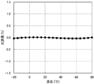
- FIG. 14 shows an example of a temperature characteristic graph of the ratio error in the measured value of the measured current I output from the signal processing circuit 8 in the current measuring device 1.
- the fluctuation range of the ratio error in the measured value of the measured current I output from the signal processing circuit 8 is set within a range of ⁇ 0.5%.
- the above ⁇ 0.5% is realized over a temperature range of 100 ° C. ( ⁇ 20 ° C. to 80 ° C.).
- the reason why the temperature range is set to ⁇ 20 ° C. or higher and 100 ° C. or lower is 100 ° C. considering the practicality of covering a normal temperature range of ⁇ 10 ° C. or higher and 40 ° C. or lower.
- such a setting within ⁇ 0.5% of the fluctuation range of the ratio error is set by adjusting the rotation angle of the Faraday rotator 3 and the ratio associated with the birefringence inherent in the sensor optical fiber 2 as described above. This is realized by error compensation and compensation of the phase difference between two linearly polarized light in the round-trip optical path between the first quarter-wave plate 4 and the second quarter-wave plate 5.
- the rotation angle of the Faraday rotator 3 is changed from 22.5 ° by ⁇ ° to reduce the fluctuation range of the ratio error of the current measuring device 1. Compensating for the relative error due to the birefringence inherent in the sensor optical fiber 2 and the position of the two linearly polarized light in the round-trip optical path between the first quarter-wave plate 4 and the second quarter-wave plate 5 It also compensates for phase differences. Therefore, all phase differences other than the phase difference of the rotation angle of the Faraday rotator 3 are compensated except for the phase difference ⁇ due to the Faraday effect inside the sensor optical fiber 2 and do not appear in the output of the current measuring device 1.
- the fluctuation range of the ratio error (about ⁇ 1.0% to about 1.2%) due to the birefringence of the sensor optical fiber is compensated, and the first quarter-wave plate 4 and the second Since the phase difference between the two linearly polarized light in the round-trip optical path between the quarter-wave plates 5 is also compensated, the fluctuation range of the ratio error in the output of the current measuring device 1 is surely kept within a range of ⁇ 0.5%. It becomes possible.
- the polarization plane holding fiber 17 and the sensor optical fiber 2 are disturbed by vibrations and temperature fluctuations. Even if the phase is changed during propagation of light, the output of the current measuring device 1 is not affected. Accordingly, it is possible to stabilize the output characteristics of the current measuring device 1.
- the reliability of the current measuring device is improved by suppressing the fluctuation range of the ratio error in the output of the current measuring device 1 within a range of ⁇ 0.5% over the temperature range of ⁇ 20 ° C. to 80 ° C. At the same time, by suppressing the fluctuation range of the ratio error to within ⁇ 0.5%, it is possible to realize a current measuring device that can be applied to protective relay applications.
- the crystal axes X41 and X51 on the optical surfaces of the two quarter-wave plates 4 and 5 are set in the same direction. Accordingly, when the current measuring apparatus 1 using circularly polarized light is configured, even if the number of constituent elements increases by the two quarter-wave plates 4 and 5, the crystal axis angle of each quarter-wave plate can be increased. There is no need to perform adjustment work or installation work. Therefore, according to the current measuring device 1 of the present invention, it is possible to simultaneously realize a high function of suppressing the relative error fluctuation range within a range of ⁇ 0.5% and facilitating the assembly work of the component elements. It becomes.
- the current measuring device 1 of the present embodiment it is necessary to install the crystal axis X61 direction of the polarization separator 6 perpendicular to the crystal axis X41 direction of the first quarter wavelength plate 4.
- the fine angle adjustment work is not necessary as compared with the case where it is installed with an angle of 45 °, for example, the assembly work between the polarization separator 6 and the first quarter-wave plate 4 is not necessary. Can be easily performed.
- the current measuring device 1 can be changed to the current measuring device 28 including, for example, two Faraday elements 27a and 27b having different Faraday rotation angles as shown in FIG.
- the total Faraday rotation angle at the time of magnetic saturation when the circularly polarized light LC1 and LC2 pass back and forth through the two Faraday elements 27a and 27b is set so as to slightly change from 45 °.
- the total of the Faraday rotation angles when the circularly polarized light LC1 and LC2 are transmitted once through the two Faraday elements 27a and 27b may be changed to 22.5 ° + a slight change ⁇ °.
- the number of Faraday elements is not limited to two, and the Faraday rotator 3 can be configured by three or more.
- FIG. 17 and 18 are graphs schematically showing temperature characteristics of the Faraday rotation angles of the Faraday elements 27a and 27b. Further, FIG. 19 shows the temperature characteristics of the Faraday rotation angle when the Faraday rotation angle temperature characteristics of the Faraday elements are combined. As shown in FIG. 17, the rotation angle of the first Faraday element 27a has a quadratic curve-like temperature dependency. Further, as shown in FIG. 18, it can be seen that the rotation angle of the second Faraday element 27b decreases uniformly in inverse proportion to the temperature rise over the temperature range of ⁇ 20 ° C. to 80 ° C.
- the temperature characteristics of the Faraday rotation angles of the first Faraday element 27a and the second Faraday element 27b are combined, the temperature characteristics of the Faraday rotation angle that decreases in a quadratic curve as the temperature rises as shown in FIG. Indicates. Therefore, by suppressing the fluctuation range of the ratio error in the measured value of the current I to be measured within the range of ⁇ 0.2% over the temperature range of ⁇ 20 ° C. to 80 ° C., it is within ⁇ 0.2% range. It is possible to use the current measuring device for applications that require temperature characteristics with a specific error of (for example, a watt-hour meter for electricity metering that requires strict metering).
- the temperature characteristic of the specific error of the lead glass fiber used for the sensor optical fiber 2 increases uniformly in proportion to the temperature rise. Therefore, in addition to providing the Faraday rotation angle decrease in the high temperature range in the Faraday elements 27a and 27b, compensation of the birefringence of the sensor optical fiber 2 and between the two quarter-wave plates 4 and 5 are performed. By compensating for the phase difference between the two linearly polarized light in the round-trip optical path, when the temperature characteristic of the specific error of the lead glass fiber used for the sensor optical fiber 2 is added, the Faraday rotation angle is reduced in the high temperature range. This compensates for the change in the specific error of the lead glass fiber. Therefore, as shown in FIG. 20, the fluctuation range of the ratio error in the measured value of the measured current I output from the signal processing circuit 8 is ⁇ 0.5% over the temperature range of ⁇ 20 ° C. to 80 ° C. Or ⁇ 0.2%).
- the current measuring device 1 Comparing the configurations of the current measuring device 1 and the current measuring device 28, the current measuring device 1 can have one Faraday rotator 3. Therefore, the configuration of the current measuring device can be simplified correspondingly, and the signal The fluctuation range of the ratio error in the measured value of the measured current I output from the processing circuit 8 can be easily adjusted. For the above reasons, the current measuring device 1 is the most preferred embodiment.
- the Faraday rotator 3 may be constituted by two or more Faraday elements. Further, when the Faraday rotator 3 is composed of two or more Faraday elements, the Faraday rotation angle of each Faraday element is configured to be different so that the temperature characteristic of each Faraday element is set to a desired characteristic. I can do it.
- the ratio within the range of ⁇ 0.2% It is possible to use the current measuring device for an application that requires a temperature characteristic of error (for example, a watt-hour meter for electricity billing that requires strict metering).
- the lead glass fiber used for the sensor optical fiber 2 has a temperature characteristic of a specific error as shown in FIG. Therefore, when the fluctuation angle of the current measuring device 1 is reduced by changing the rotation angle of the Faraday rotator 3 from 22.5 ° by ⁇ °, the temperature characteristic of the specific error of the lead glass fiber is added.
- the fluctuation range of the ratio error in the measured value of the measured current I output from the signal processing circuit 8 is ⁇ 0.5% (or ⁇ 0.2%) over the temperature range of ⁇ 20 ° C. to 80 ° C.
- the angle of ⁇ ° is adjusted so that it falls within the range of. Therefore, even if a lead glass fiber is used for the optical fiber 2 for the sensor, the fluctuation range of the ratio error in the measured value of the measured current I output from the signal processing circuit 8 is ⁇ 0.5% (or ⁇ 0.2). %).
- the optical fiber 2 for sensor may be a quartz glass fiber. Therefore, since the current measuring device of the present invention can be widely realized regardless of the type of the optical fiber for sensor, the yield of the current measuring device can be improved. Further, the first optical fiber 11 may be changed to a single mode optical fiber.
- the reciprocating optical path between the first quarter-wave plate 4 and the second quarter-wave plate 5 that propagates two linearly polarized light is not limited to the polarization plane holding fiber 17, but for example, as shown in FIG.
- two birefringent elements 20a in which the directions of the crystal axes X20a and X20b on the optical surface are aligned when viewed from the Z-axis direction, and the direction of shift movement of extraordinary rays are arranged in opposite directions. 20b.
- the lens 15 is omitted.
- the directions of the crystal axes X41 and X51 on the optical surfaces of the first quarter wavelength plate 4 and the second quarter wavelength plate 5 may be set to be orthogonal to each other. 3 to 4, the crystal axes X41 and X51 are both set in the X-axis direction. However, for example, only the direction of the crystal axis X41 may be changed to be parallel to the Y-axis direction. Or conversely, the crystal axis X41 may be set in the X-axis direction, and only the direction of the crystal axis X51 may be changed in parallel to the Y-axis direction.
- the fine angle adjustment work in the directions of the crystal axes X41 and X51 is smaller than when the crystal axes X41 and X51 are set at an angle of 45 °, for example. It is not necessary. Therefore, the assembly work between the two quarter-wave plates 4 and 5 can be easily performed.
- the crystal axis X61 direction on the optical surface of the polarization separator 6 and the crystal axis X41 direction on the optical surface of the first quarter-wave plate 4 may be changed to the same direction. .
- the crystal axis X61 direction is set to the X-axis direction.
- the position of the second optical fiber 12 may be changed so that the end face 12a comes to the position of the end face 11a of the first optical fiber 11 in FIG.
- the polarization separator 6 By setting the crystal axis X61 direction on the optical surface of the polarization separator 6 and the crystal axis X41 direction on the optical surface of the first quarter-wave plate 4 to the same direction, the polarization separator 6 There is no need to perform adjustment work or installation work of the crystal axis angle between the first quarter-wave plate 4 and the first quarter-wave plate 4. Therefore, the assembly work between the polarization separator 6 and the first quarter-wave plate 4 can be further facilitated.
- the polarization separator 6 Furthermore, by setting the crystal axis X61 direction on the optical surface of the polarization separator 6 and the crystal axes X41 and X51 directions on the optical surfaces of the two quarter-wave plates 4 and 5 to the same direction, the polarization separator There is no need to perform adjustment work and installation work of the crystal axis angle between 6 and the two quarter-wave plates 4 and 5. Therefore, the assembly work between the polarization separator 6 and the two quarter-wave plates 4 and 5 can be further facilitated.
- a lead glass fiber is used for the sensor optical fiber 2 and a round-trip optical path between the first quarter-wave plate 4 and the second quarter-wave plate 5 is used.
- PMF polarization plane holding fiber
- the Faraday rotation angle in Table 1 is the total Faraday rotation angle at the time of magnetic saturation when the circularly polarized light LC1 and LC2 are transmitted in a reciprocating manner.
- the ratio error in Table 1 is a ratio error in the measured value of the measured current I output from the signal processing circuit of the current measuring device 1. The same applies to Examples 2 to 3 below.
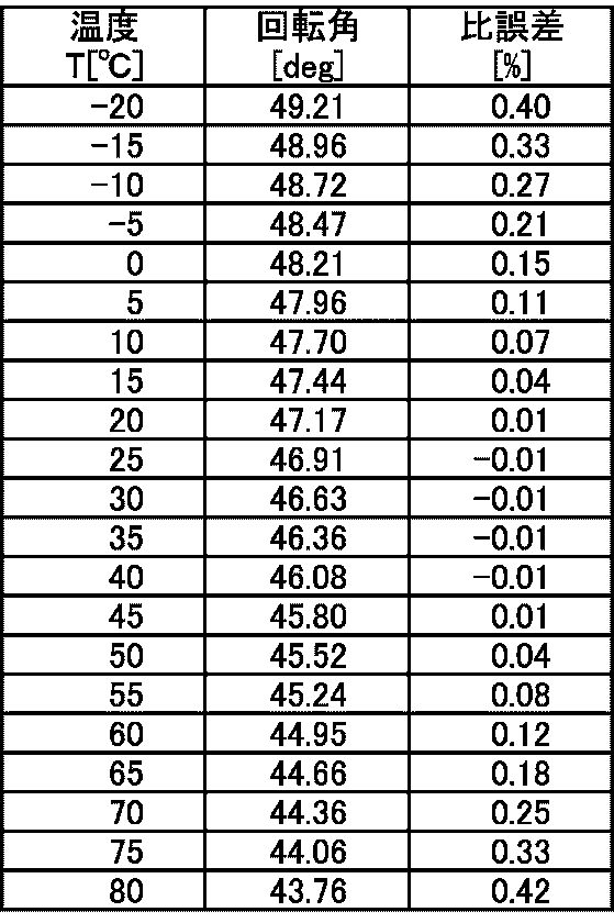
- the ratio error based on 23 ° C. can be kept within ⁇ 0.01 to 0.42%. I understand that there is. That is, the fluctuation range of the ratio error is in the range of 0.43% over the temperature range of ⁇ 20 ° C. to 80 ° C.
- Example 2 The temperature dependence of the rotation angle of the magnetic garnet in the reciprocation was expressed by the following quadratic expression (Equation 1), and the minimum value of the ratio error fluctuation range for the coefficient a and the coefficient b was calculated.
- the coefficient c was set so that the ratio error fluctuation range had a minimum value.
- Table 2 shows the relationship between the ratio error fluctuation range and the coefficients a and b.
- Table 3 shows the relationship between the Faraday rotation angle adjustment ⁇ °, the coefficient a, and the coefficient b at a temperature of 23 ° C. when the ratio error fluctuation width is the minimum value as shown in Table 2.
- Tables 2 and 3 are point-symmetric with respect to 0 of coefficient a and coefficient b. According to Table 2, the ratio error fluctuation range is minimized when the coefficient a and the coefficient b are -0.0001 and -0.02, respectively, and when the coefficient a and the coefficient b are 0.0001 and 0.02, respectively. Yes, the sign of the rotation angle adjustment amount ⁇ ° at that time is plus in the former from Table 3 and minus in the latter. Since a general magnetic garnet has a temperature characteristic of an upward convex curve and a Faraday rotation angle in which the rotation angle decreases as the temperature rises, the signs of the coefficient a and the coefficient b are negative.
- the coefficient a of the temperature-rotation angle characteristic of the magnetic garnet should be set to ⁇ 0.0001 and the coefficient b close to ⁇ 0.02 in order to reduce the ratio error fluctuation range.
- the rotation angle adjustment ⁇ ° is about 1.66 °.
- FIG. 16 A magnetic garnet having a temperature dependence of a quadratic curve is used as the Faraday element 27a in FIG. 16, and a magnetic garnet as shown in FIG. 26 is used as the Faraday element 27b.
- the temperature dependence of the Faraday elements 27a and 27b having a Faraday rotation angle of 45 ° at a temperature of 23 ° C. is shown in FIGS. 25 and 26, respectively.
- a Faraday element having a temperature dependency represented by the following formula 2 was obtained during reciprocation.
- the total Faraday rotation angle at the time of magnetic saturation at a temperature of 23 ° C. when the circularly polarized light LC1 and LC2 are transmitted in a reciprocating manner is 48.14 °.
- FIG. 27 shows the temperature dependence of the total Faraday rotation angle during reciprocation.
- Table 4 and FIG. 28 show the temperature-ratio error characteristics in the measured value of the current I to be measured, which is output from the signal processing circuit of the current measuring device 28.
- the ratio error based on a temperature of 23 ° C. is within ⁇ 0.04 to 0.01%. It became possible. That is, the fluctuation range of the ratio error is in the range of 0.05% over the temperature range of ⁇ 20 ° C. to 80 ° C.
- Example 3 Based on the study results in Table 2, a magnetic garnet was developed to reduce the ratio error with a single Faraday rotator. As a result, a magnetic garnet having a temperature dependency represented by the following formula 3 was obtained.
- the temperature dependency of the obtained magnetic garnet is shown in FIG.
- Table 5 and FIG. 30 show the temperature-ratio error characteristics in the measured value of the current I to be measured, which is output from the signal processing circuit of the current measuring device 1 having such a Faraday rotator 3.
- the ratio error range is ⁇ 0.05 to 0.01%, and the fluctuation range of the ratio error is within 0.06% over the temperature range of ⁇ 20 ° C. to 80 ° C. Become. Compared with Example 2, one Faraday rotator was able to achieve equivalent performance.
Landscapes
- Engineering & Computer Science (AREA)
- Power Engineering (AREA)
- Physics & Mathematics (AREA)
- General Physics & Mathematics (AREA)
- Measuring Instrument Details And Bridges, And Automatic Balancing Devices (AREA)
Abstract
Description
(1)本発明の電流測定装置は少なくとも、光入出射部と、センサ用光ファイバと、ファラデー回転子と、第1の1/4波長板及び第2の1/4波長板と、偏光分離器と、光源と、光電変換素子を備える信号処理回路を含み、
光入出射部は2本の導波路が配列されて構成されており、
光入出射部から順に、偏光分離器、第1の1/4波長板、第2の1/4波長板、ファラデー回転子、センサ用光ファイバが配置され、
更にセンサ用光ファイバは複屈折を有すると共に、被測定電流が流れている導体の外周に周回設置され、回転方向の異なる2つの円偏光を入射するための一端と、入射した円偏光を反射する他端を備え、
第2の1/4波長板は、センサ用光ファイバの一端側に設けられると共に、
ファラデー回転子は、センサ用光ファイバの一端側と第2の1/4波長板との間に配置され、
光源から出射された光が他端で反射されることで、偏光分離器、第1の1/4波長板、第2の1/4波長板、ファラデー回転子、及びセンサ用光ファイバを往復する往復光路が設定され、
第1の1/4波長板と第2の1/4波長板間の往復光路で2つの直線偏光が伝搬されると共に、第1の1/4波長板と第2の1/4波長板間の往復光路における2つの直線偏光の位相差が補償されており、
更に、ファラデー回転子の磁気飽和時のファラデー回転角が、温度23℃において22.5°+α°に設定され、信号処理回路から出力される被測定電流の測定値における比誤差の変動幅が±0.5%の範囲内に設定され、
第1の1/4波長板及び第2の1/4波長板のそれぞれの光学面上における結晶軸方向が直交するように設定されるか又は同一方向に設定されることを特徴とする。
図2のファラデー回転子3として、光アイソレータに用いられる、図14に示すようなファラデー回転角の温度特性を有する磁性ガーネットを使用した例を示す。温度23℃におけるファラデー回転角を22.5°+1.0°に設定したファラデー回転子を使用した。即ち、α=1.0°と設定し、円偏光LC1とLC2が往復で透過する際の、磁気飽和時における合計のファラデー回転角を47.0°と設定した。このようなファラデー回転子3を備えた電流測定装置1の信号処理回路から出力される、被測定電流Iの測定値における温度-比誤差特性を表1及び図24に示す。なお表1におけるファラデー回転角とは、円偏光LC1とLC2が往復で透過する際の磁気飽和時における合計のファラデー回転角である。また、表1における比誤差とは、電流測定装置1の信号処理回路から出力される、被測定電流Iの測定値における比誤差である。以下、実施例2乃至実施例3でも同様とする。
往復での磁性ガーネットの回転角の温度依存性を以下の2次式(数1)で表し、係数a及び係数bに対する比誤差変動幅の最小値を計算した。なお係数cは比誤差変動幅が最小値をとるように設定した。比誤差変動幅と係数aおよびbの関係を表2に示す。また、表2のように比誤差変動幅が最小値となる場合の温度23℃におけるファラデー回転角調整分α°と係数a及び係数bとの関係を表3に示す。
θF=a・T2+b・T+c なおT:温度[℃]


θF=-2.02・10-4・T2-0.0200・T+48.71 なおT:温度[℃]
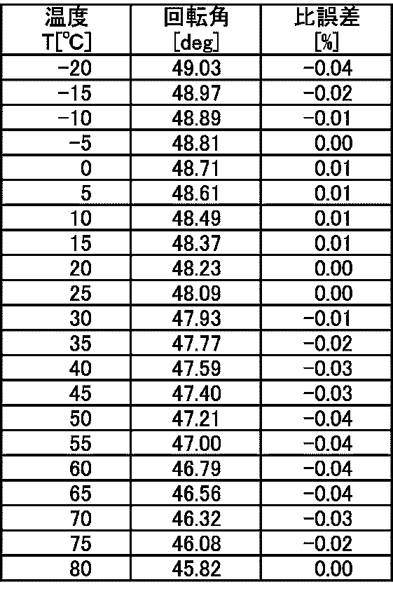
表2の検討結果をもとに1つのファラデー回転子で比誤差を低減すべく、磁性ガーネットの開発を行った。その結果以下の数3で示される温度依存性をもつ磁性ガーネットが得られた。温度23℃におけるファラデー回転角は24.22°、即ちα=1.72°と設定した。得られた磁性ガーネットの温度依存性を図29に示す。
θF=-1.64・10-4・T2-0.0185・T+48.95 なおT:温度[℃]

2 センサ用光ファイバ
2a センサ用光ファイバの一端
3 ファラデー回転子
3a 永久磁石
4 第1の1/4波長板
X41 第1の1/4波長板の光学面上における結晶軸
5 第2の1/4波長板
X51 第2の1/4波長板の光学面上における結晶軸
6 偏光分離器
X61 偏光分離器の光学面上における結晶軸
7 光源
8 信号処理回路
9 光学系
10 サーキュレータ
11 第1光ファイバ
11a 第1光ファイバの一端側の端面
12 第2光ファイバ
12a 第2光ファイバの一端側の端面
13a、13b 光電変換素子
14 フェルール
15、16 レンズ
17 偏光面保持ファイバ
17a コア
17b 応力付与部
17c クラッド
18 導体
19 ミラー
20a、20b 複屈折素子
X20a、X20b 各複屈折素子の光学面上における結晶軸
21a、21b アンプ
22a、22b バンドパスフィルタ
23a、23b ローパスフィルタ
24a、24b 除算器
25 極性反転器
26 演算器
27a、27b ファラデー素子
L1 光源から出射される直線偏光
LF、LF’ 偏光面保持ファイバのF軸方向の直線偏光
LS、LS’ 偏光面保持ファイバのS軸方向の直線偏光
LC1、LC2 円偏光
LO 常光線
LE 異常光線
I 被測定電流
Claims (12)
- 電流測定装置は少なくとも、光入出射部と、センサ用光ファイバと、ファラデー回転子と、第1の1/4波長板及び第2の1/4波長板と、偏光分離器と、光源と、光電変換素子を備える信号処理回路を含み、
前記光入出射部は2本の導波路が配列されて構成されており、
前記光入出射部から順に、前記偏光分離器、前記第1の1/4波長板、前記第2の1/4波長板、前記ファラデー回転子、前記センサ用光ファイバが配置され、
更に前記センサ用光ファイバは複屈折を有すると共に、被測定電流が流れている導体の外周に周回設置され、回転方向の異なる2つの円偏光を入射するための一端と、入射した前記円偏光を反射する他端を備え、
前記第2の1/4波長板は、前記センサ用光ファイバの一端側に設けられると共に、
前記ファラデー回転子は、前記センサ用光ファイバの一端側と前記第2の1/4波長板との間に配置され、
前記光源から出射された光が前記他端で反射されることで、前記偏光分離器、前記第1の1/4波長板、前記第2の1/4波長板、前記ファラデー回転子、及び前記センサ用光ファイバを往復する往復光路が設定され、
前記第1の1/4波長板と前記第2の1/4波長板間の前記往復光路で2つの直線偏光が伝搬されると共に、前記第1の1/4波長板と前記第2の1/4波長板間の前記往復光路における2つの前記直線偏光の位相差が補償されており、
更に、前記ファラデー回転子の磁気飽和時のファラデー回転角が、温度23℃において22.5°+α°に設定され、前記信号処理回路から出力される前記被測定電流の測定値における比誤差の変動幅が±0.5%の範囲内に設定され、
前記第1の1/4波長板及び前記第2の1/4波長板のそれぞれの光学面上における結晶軸方向が、直交するように設定されるか又は同一方向に設定されることを特徴とする電流測定装置。 - 前記偏光分離器の光学面上における結晶軸方向と、前記第1の1/4波長板の光学面上における前記結晶軸方向が、直交するように設定されるか又は同一方向に設定されることを特徴とする請求項1に記載の電流測定装置。
- 前記偏光分離器の光学面上における結晶軸方向と、前記第1の1/4波長板の光学面上における前記結晶軸方向と、前記第2の1/4波長板の光学面上における前記結晶軸方向とが、同一方向に設定されることを特徴とする請求項1に記載の電流測定装置。
- 前記変動幅が±0.5%の範囲内に設定される温度範囲が100℃であることを特徴とする請求項1乃至3の何れかに記載の電流測定装置。
- 前記100℃の温度範囲が、-20℃以上80℃以下であることを特徴とする請求項4に記載の電流測定装置。
- 前記ファラデー回転子が、温度の変化に伴って磁気飽和時のファラデー回転角が2次曲線状に変化するファラデー回転角の温度特性を有することを特徴とする請求項1乃至5の何れかに記載の電流測定装置。
- 前記ファラデー回転子が、2つ以上のファラデー素子で構成されることを特徴とする請求項1乃至6の何れかに記載の電流測定装置。
- 前記2つ以上のファラデー素子のファラデー回転角がそれぞれ異なることを特徴とする請求項7に記載の電流測定装置。
- 前記信号処理回路から出力される前記被測定電流の測定値における比誤差の変動幅が、±0.2%の範囲内に設定されることを特徴とする請求項6乃至8の何れかに記載の電流測定装置。
- 前記変動幅が±0.2%の範囲内に設定される温度範囲が100℃であることを特徴とする請求項9に記載の電流測定装置。
- 前記100℃の温度範囲が、-20℃以上80℃以下であることを特徴とする請求項10に記載の電流測定装置。
- 前記センサ用光ファイバが鉛ガラスファイバであることを特徴とする請求項1乃至11の何れかに記載の電流測定装置。
Priority Applications (7)
| Application Number | Priority Date | Filing Date | Title |
|---|---|---|---|
| CN201480012650.6A CN105026937B (zh) | 2013-03-07 | 2014-02-27 | 电流测量装置 |
| EP14760774.1A EP2966459B1 (en) | 2013-03-07 | 2014-02-27 | Current measuring device |
| RU2015142482A RU2650615C2 (ru) | 2013-03-07 | 2014-02-27 | Устройство для измерения электрического тока |
| JP2015504163A JP6450908B2 (ja) | 2013-03-07 | 2014-02-27 | 電流測定装置 |
| HK16104460.5A HK1216553B (en) | 2013-03-07 | 2014-02-27 | Current measuring device |
| US14/770,944 US9588150B2 (en) | 2013-03-07 | 2014-02-27 | Electric current measuring apparatus |
| CA2903660A CA2903660C (en) | 2013-03-07 | 2014-02-27 | Electric current measuring apparatus |
Applications Claiming Priority (2)
| Application Number | Priority Date | Filing Date | Title |
|---|---|---|---|
| JP2013-062868 | 2013-03-07 | ||
| JP2013062868 | 2013-03-07 |
Publications (1)
| Publication Number | Publication Date |
|---|---|
| WO2014136411A1 true WO2014136411A1 (ja) | 2014-09-12 |
Family
ID=51490948
Family Applications (1)
| Application Number | Title | Priority Date | Filing Date |
|---|---|---|---|
| PCT/JP2014/001080 Ceased WO2014136411A1 (ja) | 2013-03-07 | 2014-02-27 | 電流測定装置 |
Country Status (7)
| Country | Link |
|---|---|
| US (1) | US9588150B2 (ja) |
| EP (1) | EP2966459B1 (ja) |
| JP (1) | JP6450908B2 (ja) |
| CN (1) | CN105026937B (ja) |
| CA (1) | CA2903660C (ja) |
| RU (1) | RU2650615C2 (ja) |
| WO (1) | WO2014136411A1 (ja) |
Cited By (2)
| Publication number | Priority date | Publication date | Assignee | Title |
|---|---|---|---|---|
| CN107085130A (zh) * | 2016-02-16 | 2017-08-22 | 姚晓天 | 采用主动温度补偿的偏振不敏感电流和磁场传感器 |
| JP2019138775A (ja) * | 2018-02-09 | 2019-08-22 | シチズンファインデバイス株式会社 | 磁界センサ素子及び磁界センサ装置 |
Families Citing this family (9)
| Publication number | Priority date | Publication date | Assignee | Title |
|---|---|---|---|---|
| CN107091950B (zh) * | 2016-02-16 | 2021-01-19 | 姚晓天 | 基于光学传感原理集成了温度传感的反射式电流和磁场传感器 |
| KR102387464B1 (ko) * | 2017-10-12 | 2022-04-15 | 삼성전자주식회사 | 배선 회로 테스트 장치 및 방법과, 그 방법을 포함한 반도체 소자 제조방법 |
| CN108051633B (zh) * | 2017-12-23 | 2019-09-13 | 福州大学 | 一种获得拓扑绝缘体硒化铋反常线偏振光电流的方法 |
| CN108593998A (zh) * | 2018-06-26 | 2018-09-28 | 广州金升阳科技有限公司 | 一种电流指示电路 |
| CN111175557A (zh) * | 2018-11-13 | 2020-05-19 | 北京自动化控制设备研究所 | 一种高精度的光纤电流互感器 |
| CN109884368B (zh) * | 2019-01-18 | 2020-09-01 | 中国矿业大学 | 一种基于补偿线圈的地铁/煤矿杂散电流光纤传感器闭环控制装置及方法 |
| RU206139U1 (ru) * | 2020-08-26 | 2021-08-24 | Публичное акционерное общество "Межрегиональная распределительная сетевая компания Северо-Запада" | Устройство для измерения тока |
| CN116047158B (zh) * | 2022-12-29 | 2026-04-21 | 北京航天时代光电科技有限公司 | 一种单光路双通道光学电流传感器装置及自补偿测试方法 |
| DE102023205899B3 (de) | 2023-06-23 | 2024-11-21 | Technische Universität Dortmund, Körperschaft des öffentlichen Rechts | Optisch basiertes Strommesssystem und dessen Verwendung |
Citations (6)
| Publication number | Priority date | Publication date | Assignee | Title |
|---|---|---|---|---|
| JP2002529709A (ja) * | 1998-10-31 | 2002-09-10 | ザ、テクサス、エイ、アンド、エム、ユーニヴァーサティ、システィム | 光ファイバ電流センサ |
| JP2003505670A (ja) * | 1999-07-15 | 2003-02-12 | ケイブイエイチ・インダストリーズ・インコーポレーテッド | 最小構成に低減した光ファイバ電流センサ |
| WO2006022178A1 (ja) | 2004-08-25 | 2006-03-02 | The Tokyo Electric Power Company, Incorporated | 光電流センサにおける温度依存性誤差の低減方法および光電流センサ装置 |
| JP2007040884A (ja) * | 2005-08-04 | 2007-02-15 | Hitachi Cable Ltd | 反射型光ファイバ電流センサ |
| JP2010271292A (ja) | 2009-05-21 | 2010-12-02 | Adamant Kogyo Co Ltd | 電流測定装置 |
| WO2011161969A1 (ja) * | 2010-06-24 | 2011-12-29 | アダマンド工業株式会社 | 2芯光ファイバ磁界センサ |
Family Cites Families (15)
| Publication number | Priority date | Publication date | Assignee | Title |
|---|---|---|---|---|
| JPS59107273A (ja) * | 1982-12-10 | 1984-06-21 | Mitsubishi Electric Corp | 光電流・磁界センサ |
| US6563589B1 (en) | 1996-04-19 | 2003-05-13 | Kvh Industries, Inc. | Reduced minimum configuration fiber optic current sensor |
| US6023331A (en) | 1997-06-19 | 2000-02-08 | The Texas A&M University System | Fiber optic interferometric sensor and method by adding controlled amounts of circular birefringence in the sensing fiber |
| RU2120128C1 (ru) * | 1997-06-26 | 1998-10-10 | Научно-исследовательский институт импульсной техники | Устройство для измерения сверхбольших токов |
| US6122415A (en) * | 1998-09-30 | 2000-09-19 | Blake; James N. | In-line electro-optic voltage sensor |
| EP1055957A3 (en) * | 1999-05-28 | 2004-03-10 | Shin-Etsu Chemical Company, Ltd. | Faraday rotator and magneto-optical element using the same |
| WO2003075018A1 (en) * | 2002-03-01 | 2003-09-12 | Tokyo Electric Power Company | Current measuring device |
| US7652770B2 (en) * | 2005-12-07 | 2010-01-26 | Japan Science And Technology Agency | Optical nonliner evaluation device and optical switching element |
| CN101074983B (zh) * | 2006-05-17 | 2010-07-21 | 上海舜宇海逸光电技术有限公司 | 一种光纤磁光探头装置及其应用系统 |
| CN101784903B (zh) * | 2007-05-04 | 2014-12-10 | 阿海珐输配电公司 | 用于光纤传感器的自适应滤波器 |
| CA2703344A1 (en) * | 2007-10-23 | 2009-04-30 | The Tokyo Electric Power Company, Incorporated | Optical fiber electric current sensor and electric current measurment method |
| US20090214152A1 (en) * | 2008-02-21 | 2009-08-27 | Yong Huang | Polarization-maintaining optical coupler and method of making the same |
| CN101458312B (zh) * | 2009-01-04 | 2012-07-11 | 上海舜宇海逸光电技术有限公司 | 光纤磁光探测装置 |
| CN102539873B (zh) * | 2012-01-10 | 2013-12-25 | 中国科学院西安光学精密机械研究所 | 光纤电流传感器线圈及光纤电流传感器 |
| AU2013407826B2 (en) * | 2013-12-20 | 2019-02-21 | Abb Power Grids Switzerland Ag | Optical sensor |
-
2014
- 2014-02-27 CN CN201480012650.6A patent/CN105026937B/zh active Active
- 2014-02-27 RU RU2015142482A patent/RU2650615C2/ru not_active IP Right Cessation
- 2014-02-27 CA CA2903660A patent/CA2903660C/en active Active
- 2014-02-27 EP EP14760774.1A patent/EP2966459B1/en active Active
- 2014-02-27 WO PCT/JP2014/001080 patent/WO2014136411A1/ja not_active Ceased
- 2014-02-27 US US14/770,944 patent/US9588150B2/en active Active
- 2014-02-27 JP JP2015504163A patent/JP6450908B2/ja active Active
Patent Citations (6)
| Publication number | Priority date | Publication date | Assignee | Title |
|---|---|---|---|---|
| JP2002529709A (ja) * | 1998-10-31 | 2002-09-10 | ザ、テクサス、エイ、アンド、エム、ユーニヴァーサティ、システィム | 光ファイバ電流センサ |
| JP2003505670A (ja) * | 1999-07-15 | 2003-02-12 | ケイブイエイチ・インダストリーズ・インコーポレーテッド | 最小構成に低減した光ファイバ電流センサ |
| WO2006022178A1 (ja) | 2004-08-25 | 2006-03-02 | The Tokyo Electric Power Company, Incorporated | 光電流センサにおける温度依存性誤差の低減方法および光電流センサ装置 |
| JP2007040884A (ja) * | 2005-08-04 | 2007-02-15 | Hitachi Cable Ltd | 反射型光ファイバ電流センサ |
| JP2010271292A (ja) | 2009-05-21 | 2010-12-02 | Adamant Kogyo Co Ltd | 電流測定装置 |
| WO2011161969A1 (ja) * | 2010-06-24 | 2011-12-29 | アダマンド工業株式会社 | 2芯光ファイバ磁界センサ |
Non-Patent Citations (1)
| Title |
|---|
| See also references of EP2966459A4 |
Cited By (4)
| Publication number | Priority date | Publication date | Assignee | Title |
|---|---|---|---|---|
| CN107085130A (zh) * | 2016-02-16 | 2017-08-22 | 姚晓天 | 采用主动温度补偿的偏振不敏感电流和磁场传感器 |
| CN107085130B (zh) * | 2016-02-16 | 2020-05-19 | 姚晓天 | 采用主动温度补偿的偏振不敏感电流和磁场传感器 |
| JP2019138775A (ja) * | 2018-02-09 | 2019-08-22 | シチズンファインデバイス株式会社 | 磁界センサ素子及び磁界センサ装置 |
| JP7023459B2 (ja) | 2018-02-09 | 2022-02-22 | シチズンファインデバイス株式会社 | 磁界センサ素子及び磁界センサ装置 |
Also Published As
| Publication number | Publication date |
|---|---|
| JP6450908B2 (ja) | 2019-01-16 |
| EP2966459B1 (en) | 2020-01-01 |
| US9588150B2 (en) | 2017-03-07 |
| JPWO2014136411A1 (ja) | 2017-02-09 |
| CN105026937A (zh) | 2015-11-04 |
| RU2015142482A (ru) | 2017-04-11 |
| EP2966459A4 (en) | 2016-11-09 |
| HK1216553A1 (zh) | 2016-11-18 |
| US20160011237A1 (en) | 2016-01-14 |
| EP2966459A1 (en) | 2016-01-13 |
| RU2650615C2 (ru) | 2018-04-16 |
| CA2903660C (en) | 2021-11-09 |
| CN105026937B (zh) | 2018-05-01 |
| CA2903660A1 (en) | 2014-09-12 |
Similar Documents
| Publication | Publication Date | Title |
|---|---|---|
| JP6450908B2 (ja) | 電流測定装置 | |
| CN102906629B (zh) | 光纤双折射补偿镜及电流传感器 | |
| CN102959422B (zh) | 双芯光纤磁场传感器 | |
| JP5756966B2 (ja) | 電流測定装置 | |
| CN100334454C (zh) | 电流测量装置 | |
| CN113167583B (zh) | 紧凑型光纤萨格纳克干涉仪 | |
| US11047885B2 (en) | Sensor device having an integrated beam splitter | |
| JP2017015576A (ja) | サニャック干渉型光電流センサ及びその信号処理方法 | |
| CN101975975B (zh) | 零温度系数光学波片与偏振态变换器 | |
| JP3587302B2 (ja) | フォトニック結晶作製方法およびフォトニック結晶を用いた光デバイス | |
| HK1216553B (en) | Current measuring device | |
| JPH04125602A (ja) | 光導波路型偏光子 | |
| KR102729566B1 (ko) | 일체형 광학계 기반의 광전류 센서 시스템 | |
| HK1167462B (en) | Electric current measuring instrument | |
| JP2004264872A (ja) | フォトニック結晶を用いた光デバイス | |
| HK1182179B (en) | Two-core optical fiber magnetic field sensor |
Legal Events
| Date | Code | Title | Description |
|---|---|---|---|
| WWE | Wipo information: entry into national phase |
Ref document number: 201480012650.6 Country of ref document: CN |
|
| 121 | Ep: the epo has been informed by wipo that ep was designated in this application |
Ref document number: 14760774 Country of ref document: EP Kind code of ref document: A1 |
|
| ENP | Entry into the national phase |
Ref document number: 2015504163 Country of ref document: JP Kind code of ref document: A |
|
| WWE | Wipo information: entry into national phase |
Ref document number: 14770944 Country of ref document: US Ref document number: 2014760774 Country of ref document: EP |
|
| ENP | Entry into the national phase |
Ref document number: 2903660 Country of ref document: CA |
|
| NENP | Non-entry into the national phase |
Ref country code: DE |
|
| ENP | Entry into the national phase |
Ref document number: 2015142482 Country of ref document: RU Kind code of ref document: A |