WO2014136423A1 - 車両用空調装置およびその構成ユニット - Google Patents
車両用空調装置およびその構成ユニット Download PDFInfo
- Publication number
- WO2014136423A1 WO2014136423A1 PCT/JP2014/001131 JP2014001131W WO2014136423A1 WO 2014136423 A1 WO2014136423 A1 WO 2014136423A1 JP 2014001131 W JP2014001131 W JP 2014001131W WO 2014136423 A1 WO2014136423 A1 WO 2014136423A1
- Authority
- WO
- WIPO (PCT)
- Prior art keywords
- refrigerant
- heat exchanger
- water
- coolant
- heat
- Prior art date
- Legal status (The legal status is an assumption and is not a legal conclusion. Google has not performed a legal analysis and makes no representation as to the accuracy of the status listed.)
- Ceased
Links
Images


Classifications
-
- B—PERFORMING OPERATIONS; TRANSPORTING
- B60—VEHICLES IN GENERAL
- B60H—ARRANGEMENTS OF HEATING, COOLING, VENTILATING OR OTHER AIR-TREATING DEVICES SPECIALLY ADAPTED FOR PASSENGER OR GOODS SPACES OF VEHICLES
- B60H1/00—Heating, cooling or ventilating devices
- B60H1/00007—Combined heating, ventilating, or cooling devices
-
- B—PERFORMING OPERATIONS; TRANSPORTING
- B60—VEHICLES IN GENERAL
- B60H—ARRANGEMENTS OF HEATING, COOLING, VENTILATING OR OTHER AIR-TREATING DEVICES SPECIALLY ADAPTED FOR PASSENGER OR GOODS SPACES OF VEHICLES
- B60H1/00—Heating, cooling or ventilating devices
- B60H1/00642—Control systems or circuits; Control members or indication devices for heating, cooling or ventilating devices
- B60H1/00814—Control systems or circuits characterised by their output, for controlling particular components of the heating, cooling or ventilating installation
- B60H1/00878—Control systems or circuits characterised by their output, for controlling particular components of the heating, cooling or ventilating installation the components being temperature regulating devices
- B60H1/00899—Controlling the flow of liquid in a heat pump system
- B60H1/00921—Controlling the flow of liquid in a heat pump system where the flow direction of the refrigerant does not change and there is an extra subcondenser, e.g. in an air duct
-
- B—PERFORMING OPERATIONS; TRANSPORTING
- B60—VEHICLES IN GENERAL
- B60H—ARRANGEMENTS OF HEATING, COOLING, VENTILATING OR OTHER AIR-TREATING DEVICES SPECIALLY ADAPTED FOR PASSENGER OR GOODS SPACES OF VEHICLES
- B60H1/00—Heating, cooling or ventilating devices
- B60H1/32—Cooling devices
- B60H1/3204—Cooling devices using compression
- B60H1/3228—Cooling devices using compression characterised by refrigerant circuit configurations
- B60H1/32284—Cooling devices using compression characterised by refrigerant circuit configurations comprising two or more secondary circuits, e.g. at evaporator and condenser side
-
- B—PERFORMING OPERATIONS; TRANSPORTING
- B60—VEHICLES IN GENERAL
- B60H—ARRANGEMENTS OF HEATING, COOLING, VENTILATING OR OTHER AIR-TREATING DEVICES SPECIALLY ADAPTED FOR PASSENGER OR GOODS SPACES OF VEHICLES
- B60H1/00—Heating, cooling or ventilating devices
- B60H1/00642—Control systems or circuits; Control members or indication devices for heating, cooling or ventilating devices
- B60H1/00814—Control systems or circuits characterised by their output, for controlling particular components of the heating, cooling or ventilating installation
- B60H1/00878—Control systems or circuits characterised by their output, for controlling particular components of the heating, cooling or ventilating installation the components being temperature regulating devices
- B60H2001/00928—Control systems or circuits characterised by their output, for controlling particular components of the heating, cooling or ventilating installation the components being temperature regulating devices comprising a secondary circuit
-
- B—PERFORMING OPERATIONS; TRANSPORTING
- B60—VEHICLES IN GENERAL
- B60H—ARRANGEMENTS OF HEATING, COOLING, VENTILATING OR OTHER AIR-TREATING DEVICES SPECIALLY ADAPTED FOR PASSENGER OR GOODS SPACES OF VEHICLES
- B60H1/00—Heating, cooling or ventilating devices
- B60H1/00642—Control systems or circuits; Control members or indication devices for heating, cooling or ventilating devices
- B60H1/00814—Control systems or circuits characterised by their output, for controlling particular components of the heating, cooling or ventilating installation
- B60H1/00878—Control systems or circuits characterised by their output, for controlling particular components of the heating, cooling or ventilating installation the components being temperature regulating devices
- B60H2001/00949—Control systems or circuits characterised by their output, for controlling particular components of the heating, cooling or ventilating installation the components being temperature regulating devices comprising additional heating/cooling sources, e.g. second evaporator
Definitions
- the present invention relates to a vehicle air conditioner and a component unit of the vehicle air conditioner.
- Patent Document 1 a vehicle air conditioner that uses a heat pump to cool and heat the passenger compartment has been proposed (see, for example, Patent Document 1).
- the conventional vehicle air conditioner that heats the vehicle interior using the heat of the engine coolant has a problem that the vehicle interior cannot be heated when the water temperature of the engine coolant is not high.
- Such a problem also applies to a case in which exhaust heat is obtained from a heat generating component other than the engine, such as a secondary battery that supplies electric power for traveling or an electric motor for traveling, in an electric vehicle and used for heating. To occur.
- a heat generating component other than the engine such as a secondary battery that supplies electric power for traveling or an electric motor for traveling, in an electric vehicle and used for heating.
- An object of the present invention is to provide a vehicle air conditioner capable of heating a passenger compartment with high efficiency even when the outside air temperature is low and a large amount of exhaust heat cannot be obtained from the heat generating parts of the vehicle.
- a vehicle air conditioner includes a first water refrigerant heat exchanger that exchanges heat between a low-temperature and low-pressure refrigerant in a heat pump and a coolant of a heat generating component of the vehicle to vaporize the refrigerant,
- a second water refrigerant heat exchanger that exchanges heat between the high-temperature and high-pressure refrigerant in the heat pump and the coolant for heat transport to condense the refrigerant, and the second water refrigerant heat exchanger includes a vehicle A heater core that applies heat to the air sent to the room and a coolant are connected to be able to circulate, and the first water-refrigerant heat exchanger is not connected to the heater core, and the cooling passage for the heat-generating component and the coolant The structure is connected so that it can be circulated.
- the structural unit of the vehicle air conditioner includes a first water refrigerant heat exchanger that exchanges heat between a low-temperature and low-pressure refrigerant and a coolant in the heat pump to vaporize the refrigerant, and the heat pump.
- a second water refrigerant heat exchanger that condenses the refrigerant by exchanging heat between the high-temperature and high-pressure refrigerant and the coolant; and the first water refrigerant heat exchanger and the second water refrigerant heat exchanger are accommodated.
- a housing to be integrated; a first introduction pipe for guiding an inlet of the coolant of the first water refrigerant heat exchanger to the outside of the housing; and an outlet of the coolant of the first water refrigerant heat exchanger.
- a first lead-out pipe that leads to the outside of the body, a second introduction pipe that leads the coolant inlet of the second water refrigerant heat exchanger to the outside of the housing, and a coolant of the second water refrigerant heat exchanger
- a second outlet pipe that guides the outlet to the outside of the housing is employed.
- the vehicle interior can be heated with high efficiency.
- the block diagram which shows the vehicle air conditioner of embodiment of this invention The figure explaining operation of the heating mode at the time of engine coolant medium temperature
- the figure explaining operation of dehumidification mode at the time of engine coolant middle temperature The figure explaining operation of heating mode at the time of high temperature of engine coolant
- the figure explaining the heating efficiency of this Embodiment (A) and conventional example (B) at the time of medium temperature of engine coolant The figure explaining the heating efficiency of this Embodiment (A) and the comparative example (B) at the time of engine coolant medium temperature
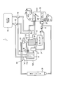
- FIG. 1 is a configuration diagram showing a vehicle air conditioner according to an embodiment of the present invention.
- a vehicle air conditioner 1 is a device that is mounted on a vehicle having an engine (internal combustion engine) and performs heating, dehumidification, and cooling of the vehicle interior.
- the vehicle air conditioner 1 includes a component unit 10, a compressor (compressor) 38, an engine cooling unit 40, three-way valves 42 and 43, a heater core 44, an evaporator 48, an expansion valve 37, an outdoor capacitor 39, and a check valve. 15, and a coolant pipe and a refrigerant pipe connecting between them.
- the heater core 44 and the evaporator 48 are disposed in an intake passage of an HVAC (Heating, Ventilation, and Air Conditioning) 70.
- the HVAC 70 is provided with a fan F1 through which intake air flows.
- the compressor 38 is driven by engine power or electricity to compress the sucked refrigerant into a high temperature and high pressure and discharge it.
- the compressed refrigerant is sent to the constituent unit 10.
- the engine cooling unit 40 includes a water jacket for flowing a coolant around the engine and a pump for flowing the coolant to the water jacket, and releases heat from the engine to the coolant flowing in the water jacket.
- the pump is rotated by the power of the engine, for example.
- the engine cooling unit 40 may include a radiator that releases heat to the outside air when the amount of exhaust heat of the engine increases.
- the heater core 44 is a device that exchanges heat between the coolant and air, and is disposed in the intake passage of the HVAC 70 that supplies air into the passenger compartment.
- the heater core 44 is supplied with a heated coolant and releases heat to the intake air that is sent into the passenger compartment during the heating operation.
- the three-way valves 42 and 43 are valves for switching whether the coolant passage of the engine cooling unit 40 is connected to the component unit 10 side or the heater core 44 side.
- the means for performing this switching is not limited to a three-way valve, and for example, a plurality of valves may be combined.
- the three-way valves 42 and 43 can perform the above switching by, for example, electrical control.
- the evaporator 48 is a device that exchanges heat between the low-temperature and low-pressure refrigerant and the air, and is disposed in the intake passage of the HVAC 70.
- the evaporator 48 is supplied with a low-temperature and low-pressure refrigerant during the cooling operation or the dehumidifying operation, and cools the intake air supplied into the passenger compartment.
- the expansion valve 37 expands the high-pressure refrigerant to a low temperature and low pressure and discharges it to the evaporator 48.
- the expansion valve 37 is disposed in the vicinity of the evaporator 48.
- the outdoor condenser 39 has a passage through which the refrigerant flows and a passage through which the air flows.
- the outdoor condenser 39 is disposed near the top of the vehicle in the engine room and exchanges heat between the refrigerant and the outside air.
- a high-temperature and high-pressure refrigerant is passed through the outdoor condenser 39 in the cooling mode and the dehumidifying mode, and heat is discharged from the refrigerant to the outside air. Outside air is blown onto the outdoor condenser 39 by, for example, a fan.
- the component unit 10 is integrally formed by being covered with a housing 10A.
- the constituent unit 10 includes a first water refrigerant heat exchanger 11, a second water refrigerant heat exchanger 12, an on-off valve 13, an expansion valve 14 with a solenoid valve, a water pump 16, and an accumulator 17. .
- the first water refrigerant heat exchanger 11 has a passage through which a low-temperature and low-pressure refrigerant flows and a passage through which a coolant flows, and performs heat exchange between the refrigerant and the coolant.
- the first water refrigerant heat exchanger 11 is supplied with a low-temperature and low-pressure refrigerant in a predetermined operation mode, and a coolant is circulated between the engine coolant 40 and the coolant. Transfers heat to low-temperature and low-pressure refrigerant.
- the second water refrigerant heat exchanger 12 has a passage through which a high-temperature and high-pressure refrigerant flows and a passage through which a cooling liquid flows, and performs heat exchange between the refrigerant and the cooling liquid.
- a coolant is circulated between the heater core 44 and the heat from the high-temperature and high-pressure refrigerant to the coolant in a predetermined operation mode.
- Two pipes h1 and h2 respectively connected to the inlet and outlet of the coolant of the first water refrigerant heat exchanger 11 are directly extended to the outside of the housing 10A and connected to the three-way valves 42 and 43. ing.
- a water pump 16 is provided on one of the two pipes h3 and h4 connected to the coolant inlet and the outlet of the second water refrigerant heat exchanger 12, respectively.
- These two pipes h3 and h4 extend to the outside of the housing 10A and are connected to the heater core 44. Further, in the middle of these two pipes h3 and h4, pipes extending from the engine cooling section 40 via the three-way valves 42 and 43 are joined and connected.
- the water pump 16 is a pump capable of circulating the coolant between the second water refrigerant heat exchanger 12 and the heater core 44 by, for example, electrical driving.
- the refrigerant pipe j1 connected to the refrigerant inlet of the second water refrigerant heat exchanger 12 extends to the outside of the housing 10A and is connected to the discharge port of the compressor 38.
- the refrigerant pipe j2 connected to the refrigerant outlet of the second water refrigerant heat exchanger 12 is branched into two inside the housing 10A.
- One of the branched refrigerant pipes extends to the outside of the housing 10 ⁇ / b> A via the on-off valve 13.
- the other of the branched refrigerant pipes j3 is connected to the refrigerant inlet of the first water refrigerant heat exchanger 11 via an expansion valve 14 with a solenoid valve.
- the refrigerant pipe j4 connected to the refrigerant outlet of the first water refrigerant heat exchanger 11 is extended to the outside of the housing 10A via the accumulator 17 and connected to the refrigerant inlet of the compressor 38.
- the refrigerant pipe of the evaporator 48 is also joined to the refrigerant suction port of the compressor 38.
- the on-off valve 13 is a valve that switches between opening and closing of the refrigerant pipe, for example, by electrical control.
- the expansion valve 14 with a solenoid valve is a valve that functions as an expansion valve when the refrigerant pipe is opened and closed, for example, by electrical control.
- the accumulator 17 separates the vaporized refrigerant that has passed through the first water refrigerant heat exchanger 11 and the non-vaporized refrigerant, and sends only the vaporized refrigerant to the compressor 38.
- the check valve 15 is provided between the compressor 38 and the evaporator 48, and is a valve that prevents the refrigerant from flowing back in the operation mode in which the refrigerant does not flow through the outdoor condenser 39 and the evaporator 48.
- This check valve 15 has the following effects. For example, consider an operation mode in which the on-off valve 13 is closed and the refrigerant flows through the refrigerant circuit passing through the first water refrigerant heat exchanger 11 and the second water refrigerant heat exchanger 12. In this operation mode, since the on-off valve 13 is closed, the refrigerant circuit passing through the outdoor condenser 39 and the evaporator 48 is shut off. However, even in this case, if the outside air is low, the refrigerant may stagnate in the outdoor condenser 39 exposed to the outside air, and the refrigerant pressure in the outdoor condenser 39 and the evaporator 48 may be low.
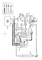
- FIG. 2 is a diagram for explaining the operation in the heating mode when the engine coolant is at a medium temperature.
- the on-off valve 13 is closed, the expansion valve 14 with a solenoid valve is opened, and the water pump 16 Is turned on, and the passages of the three-way valves 42 and 43 are switched to the first water refrigerant heat exchanger 11 side.
- a medium temperature for example, less than 60 ° C.
- the compressor 38 when the compressor 38 is operated, the refrigerant passes through the second water refrigerant heat exchanger 12, the expansion valve 14 with a solenoid valve, the first water refrigerant heat exchanger 11, the accumulator 17, and the compressor 38 in this order. It flows cyclically.
- the high-temperature and high-pressure refrigerant compressed by the compressor 38 releases heat to the coolant in the second water refrigerant heat exchanger 12 and condenses. Further, the low-temperature and low-pressure refrigerant expanded by the expansion valve 14 with a solenoid valve is vaporized by absorbing heat from the coolant in the first water refrigerant heat exchanger 11.
- Coolant flows in two paths and flows independently.
- the coolant in the first path flows cyclically between the engine cooling unit 40 and the first water refrigerant heat exchanger 11.
- the coolant in the first path cools the engine in the engine cooling unit 40 and releases heat to the low-temperature and low-pressure refrigerant in the first water-refrigerant heat exchanger 11.
- the coolant in the second path flows cyclically between the second water refrigerant heat exchanger 12 and the heater core 44 by the water pump 16.
- the coolant in the second path absorbs heat from the high-temperature and high-pressure refrigerant in the second water-refrigerant heat exchanger 12 and releases heat to the intake air that is sent into the passenger compartment in the heater core 44.
- FIG. 3 is a diagram for explaining the operation in the dehumidifying mode when the engine coolant is at a medium temperature.
- the on-off valve 13 When the operation of the dehumidifying mode is requested when the engine coolant is at a medium temperature (for example, less than 60 ° C.), the on-off valve 13 is switched to open from the state of the heating mode at the medium temperature in FIG.
- the compressor 38, the second water refrigerant heat exchanger 12, the outdoor condenser 39, the expansion valve 37, and the evaporator 48 are A refrigerant flow circulating in this order is generated.
- the low-temperature and low-pressure refrigerant flows through the evaporator 48 by this refrigerant flow, and the intake air sent into the passenger compartment can be dehumidified.
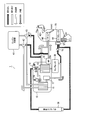
- FIG. 4 is a diagram for explaining the operation in the heating mode when the engine coolant is at a high temperature.
- the on-off valve 13 is opened, the expansion valve 14 with a solenoid valve is closed, and the water pump 16 Is turned off, and the passages of the three-way valves 42 and 43 are switched to the heater core 44 side.
- the high-temperature coolant can flow through the heater core 44 to warm the intake air sent to the passenger compartment.
- the compressor 38 is operated, so that the refrigerant passes through the second water refrigerant heat exchanger 12, the outdoor condenser 39, the expansion valve 37, the evaporator 48, and the compressor 38 in this order. Flows cyclically.
- the high-temperature and high-pressure refrigerant compressed by the compressor 38 passes through the second water refrigerant heat exchanger 12 in which the coolant does not flow almost without heat exchange, and is condensed by releasing heat to the outdoor air in the outdoor condenser 39.
- the low-temperature and low-pressure refrigerant expanded by the expansion valve 37 absorbs heat from the intake air sent into the passenger compartment by the evaporator 48 and vaporizes. Thereby, dehumidification of intake air can be performed.
- the door of the heater core 44 is closed with the refrigerant and the coolant flowing in FIG.
- the intake air passing through the HVAC 70 is cooled by the evaporator 48, and is sent directly to the vehicle interior without passing through the heater core 44, thereby cooling the vehicle interior.
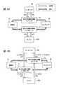
- FIG. 5 is a diagram for explaining the heating efficiency between the present embodiment (A) and the conventional example (B) when the engine coolant is at a medium temperature.
- FIG. 5 an example of the stable temperature of the coolant flowing in each part is shown beside the arrow indicating the flow of the coolant.
- the heating mode (A) at the middle temperature of the present embodiment and the conventional Comparison with the heating mode (B) in the example is performed.
- 5B is a configuration having a heat pump system including a compressor 51, a water-refrigerant heat exchanger 52 that functions as a condenser, an expansion valve 53, and an outdoor heat exchanger 54 that functions as an evaporator.
- the engine coolant is heated by the water-refrigerant heat exchanger 52 and sent to the heater core 44.
- This configuration corresponds to the configuration of FIG.
- the medium temperature coolant is supplied to the first water refrigerant heat exchanger 11 that functions as an evaporator.
- the heat pump system operates efficiently, and a large amount of heat can be transferred from the first water refrigerant heat exchanger 11 to the second water refrigerant heat exchanger 12 with low power consumption. Therefore, the second water refrigerant heat exchanger 12 is maintained at a high temperature, and the vehicle interior can be sufficiently warmed by supplying a high-temperature coolant to the heater core 44.
- the amount of the coolant flowing through the heater core 44 depends on the rotational speed of the coolant pump of the engine 40A.
- the flow rate of the coolant in the heater core 44 can be controlled independently of the flow rate of the coolant in the engine 40A. Therefore, in the present embodiment, even when the engine 40A is stopped due to idling stop or the like, it is possible to maintain the heating capacity of the passenger compartment by flowing the coolant through the heater core 44.
- FIG. 6 is a diagram for explaining the heating efficiency of the present embodiment (A) and the comparative example (B) when the engine coolant is at a medium temperature.
- FIG. 6 an example of a stable temperature of the coolant flowing through each part is shown alongside the arrow indicating the flow of the coolant.
- FIG. 6B the unstable temperature of the coolant is shown in parentheses.
- the comparative example of FIG. 6B has the same heat pump system as that of the present embodiment, while the coolant is used as the heater core 44, the first water refrigerant heat exchanger 11, the cooling passage of the engine 40A, the second water refrigerant heat.
- the configuration is such that it flows through the exchanger 12 in this order.
- the compressor 38 is driven in the same manner as in the present embodiment, and the heater core 44 is heated to a high temperature (for example, an unstable temperature (1) 70 ° C.) as in the present embodiment. It is assumed that the cooling liquid is supplied.
- a high temperature for example, an unstable temperature (1) 70 ° C.
- the coolant that has passed through the heater core 44 is sent to the first water-refrigerant heat exchanger 11. Therefore, in the case of the above assumption, the temperature of the coolant input to the first water-refrigerant heat exchanger 11 is higher than that in the present embodiment (for example, an unstable temperature (1) 50 ° C.). As a result, the temperature of the coolant that passes through the first water-refrigerant heat exchanger 11 and is sent to the engine 40A also becomes higher than that in the present embodiment (for example, an unstable temperature (1) 25 ° C.).
- the temperature difference between the coolant sent from the first water-refrigerant heat exchanger 11 and the engine 40A becomes small, so that the heat radiation from the engine 40A to the coolant is small.
- the coolant of the engine 40A is sent to the second water refrigerant heat exchanger 12.
- the temperature of the coolant input to the second water refrigerant heat exchanger 12 is lower than that of the present embodiment (for example, an unstable temperature (1) 40 ° C.).
- the temperature of the coolant output from the second water refrigerant heat exchanger 12 cannot be maintained, and the temperature becomes low (for example, an unstable temperature (2) 65 ° C.).
- the stable temperature of the coolant in each part of the comparative example of FIG. 6B becomes lower on the heater core 44 side and higher on the engine 40A side than in the present embodiment. That is, it can be seen that the heating efficiency of the comparative example of FIG. 6B is lower than that of the heating mode at the medium temperature of the engine coolant of the present embodiment.
- the flow rate of the coolant in the heater core 44 depends on the number of revolutions of the coolant pump in the engine 40A.
- the coolant flow rate of the heater core 44 can be controlled independently of the coolant flow rate of the engine 40A. Therefore, in the present embodiment, for example, even when the engine 40A is stopped due to idling stop or the like, it is possible to flow the coolant through the heater core 44 and continue heating the vehicle interior to maintain the heating capacity.
- the vehicle interior can be heated with high efficiency even when the outside air temperature is low and the engine temperature is not so high.
- the vehicle air conditioner 1 according to the present embodiment has an effect that the vehicle air conditioner 1 can be mounted by simply adding the configuration unit 10 and changing the connection of the pipes to the vehicle having the conventional air conditioning equipment.
- some conventional vehicles have an air conditioning system that uses a heat pump to cool the passenger compartment during warm weather while heating the passenger compartment using the heat of the engine coolant during cold weather.
- air conditioning equipment includes an outdoor condenser 39, a compressor 38, an expansion valve 37, an evaporator 48, an engine cooling unit 40, and a heater core 44. Therefore, for such a vehicle, the vehicle air conditioner 1 of the present embodiment can be realized simply by adding the configuration unit 10 and changing the pipe connection.
- the vehicle air conditioner 1 of the present embodiment the following advantages are obtained when compared with the air conditioner of Comparative Example 2.
- an outdoor heat exchanger (corresponding to the outdoor condenser 39 in the present embodiment) that discharges heat from the refrigerant to the outside air during the cooling operation is used to take heat from the outside air into the refrigerant during the heating operation.
- a vehicle air conditioner used as an evaporator By using the outdoor heat exchanger as an evaporator and taking heat into the low-temperature and low-pressure refrigerant, the vehicle interior can be heated by the heat pump.
- an outdoor exchanger designed to be used as a capacitor during warm weather is used as an evaporator during cold weather. Since these two use conditions are greatly different, in the configuration of Comparative Example 2, when the outdoor heat exchanger is used as an evaporator, there may be a problem that the efficiency of heat exchange does not increase. For example, there may be a problem that frost and freezing are likely to occur in the outdoor heat exchanger. In addition, the refrigerant passage adapted to the high-temperature and high-pressure refrigerant may not be adapted to the refrigerant expanded to a low temperature and low pressure, and there may be a problem that a sufficient amount of heat exchange cannot be obtained.
- the outdoor condenser 39 is not used as an evaporator, and at the time of heating operation, the first water refrigerant heat exchanger 11 to which engine coolant is supplied is used for low temperature and low pressure. Heat exchange with the refrigerant is performed to vaporize the refrigerant. Therefore, the supply of heat to the low-temperature and low-pressure refrigerant and the vaporization of the low-temperature and low-pressure refrigerant during the heating operation can be performed easily and reliably, and the heating capacity can be improved.
- the accumulator 17 of the constituent unit 10 can be omitted because the refrigerant can be sufficiently vaporized by the first water refrigerant heat exchanger 11.
- the on-off valve 13 and the water pump 16 may be provided outside the constituent unit 10 without being included in the constituent unit 10.
- the expansion valve 14 with a solenoid valve may be replaced with two parts including an on-off valve and an expansion valve, and the check valve 15 may be replaced with an electromagnetic on-off valve.
- the path through which the second water refrigerant heat exchanger 12 is passed has been described as an example.
- the refrigerant passage may be branched into two at the rear stage of the compressor 38 so that the refrigerant discharged from the compressor 38 is switched to the outdoor condenser 39 or the second water refrigerant heat exchanger.
- the configuration (three-way valves 42, 43) for switching the engine coolant passage is included, but this configuration may be omitted.
- the engine is used as an example of the vehicle heating part.
- various heating components such as an electric motor for traveling in an electric vehicle and a secondary battery that supplies electric power for traveling may be adopted as the heating component of the vehicle.
- the present invention can be used for a vehicle air conditioner mounted on various vehicles such as an engine vehicle, an electric vehicle, or a HEV vehicle.
Landscapes
- Physics & Mathematics (AREA)
- Thermal Sciences (AREA)
- Engineering & Computer Science (AREA)
- Mechanical Engineering (AREA)
- Air-Conditioning For Vehicles (AREA)
Abstract
外気温が低く、車両の発熱部品から多くの排熱を得られない場合でも、高い効率で車室内の暖房を行うことのできる車両用空調装置を提供すること。この車両用空調装置は、ヒートポンプにおける低温低圧の冷媒と車両の発熱部品の冷却液との間で熱を交換して冷媒を気化させる第1水冷媒熱交換器と、ヒートポンプにおける高温高圧の冷媒と熱輸送用の冷却液との間で熱を交換して冷媒を凝縮させる第2水冷媒熱交換器と、を具備し、第2水冷媒熱交換器は、車室内へ送られる空気に熱を与えるヒーターコアと冷却液を循環可能に接続され、第1水冷媒熱交換器は、ヒーターコアを介さずに、発熱部品の冷却用の通路と冷却液を循環可能に接続されている、構成を採る。
Description
本発明は、車両用空調装置および車両用空調装置の構成ユニットに関する。
従来、ヒートポンプを利用して車室内の冷房および暖房を行う車両用空調装置が提案されている(例えば特許文献1を参照)。
また、以前より、エンジン冷却液の熱を利用して車室内の暖房を行う車両用空調装置がある。さらに、エンジン冷却液をヒートポンプの高温高圧冷媒によりさらに加熱して、この冷却液で車室内の暖房を行う車両用空調装置の提案もある(例えば特許文献1の図18)。
しかしながら、エンジン冷却液の熱を利用して車室内の暖房を行う従来の車両用空調装置では、エンジン冷却液の水温が高くない場合に、車室内を暖房することができないという課題がある。
近年では、エンジンの高効率化に伴って、エンジン稼働中でもエンジン冷却液の水温が余り高くならない車両がある。さらに、アイドリングストップ車、HEV(Hybrid Electric Vehicle)、P-HEV(Plug-in Hybrid Electric Vehicle)などでは、エンジンの稼働が間欠的になることで、エンジン冷却液の水温が余り高くならない状況がしばしば生じる。
一方、エンジン冷却液をヒートポンプの高温高圧冷媒によりさらに加熱して、この冷却液で車室内の暖房を行う上記従来の車両用空調装置では、エンジン冷却液の水温が余り高くならない状況でも、車室内の暖房を行うことが可能となる。しかしながら、このような車両用空調装置では、外気温が低く、エンジン冷却液の水温が余り高くない場合に、暖房効率が低下するということが分かった(詳細は、図5および図6を用いて後述する)。
このような課題は、電気自動車において、走行用の電力を供給する二次電池、または、走行用の電気モータ等、エンジン以外の発熱部品から排熱を得て暖房に利用する場合にも、同様に生じる。
本発明の目的は、外気温が低く、車両の発熱部品から多くの排熱を得られない場合でも、高い効率で車室内の暖房を行うことのできる車両用空調装置を提供することである。
本発明の一態様に係る車両用空調装置は、ヒートポンプにおける低温低圧の冷媒と車両の発熱部品の冷却液との間で熱を交換して冷媒を気化させる第1水冷媒熱交換器と、前記ヒートポンプにおける高温高圧の冷媒と熱輸送用の冷却液との間で熱を交換して冷媒を凝縮させる第2水冷媒熱交換器と、を具備し、前記第2水冷媒熱交換器は、車室内へ送られる空気に熱を与えるヒーターコアと冷却液を循環可能に接続され、前記第1水冷媒熱交換器は、前記ヒーターコアを介さずに、前記発熱部品の冷却用の通路と冷却液を循環可能に接続されている、構成を採る。
本発明の一態様に係る車両用空調装置の構成ユニットは、ヒートポンプにおける低温低圧の冷媒と冷却液との間で熱を交換して冷媒を気化させる第1水冷媒熱交換器と、前記ヒートポンプにおける高温高圧の冷媒と冷却液との間で熱を交換して冷媒を凝縮させる第2水冷媒熱交換器と、前記第1水冷媒熱交換器および前記第2水冷媒熱交換器を収容して一体化する筐体と、前記第1水冷媒熱交換器の冷却液の入口を前記筐体の外部に導く第1導入管と、前記第1水冷媒熱交換器の冷却液の出口を前記筐体の外部に導く第1導出管と、前記第2水冷媒熱交換器の冷却液の入口を前記筐体の外部に導く第2導入管と、前記第2水冷媒熱交換器の冷却液の出口を前記筐体の外部に導く第2導出管と、を具備する構成を採る。
本発明によれば、外気温が低く、車両の発熱部品から多くの排熱を得られない場合でも、高い効率で車室内の暖房を行うことができる。
以下、本発明の各実施の形態について図面を参照して詳細に説明する。
図1は、本発明の実施の形態の車両用空調装置を示す構成図である。
本発明の実施形態の車両用空調装置1は、エンジン(内燃機関)を有する車両に搭載されて、車室内の暖房、除湿および冷房を行う装置である。
実施形態の車両用空調装置1は、構成ユニット10、コンプレッサ(圧縮機)38、エンジン冷却部40、三方弁42,43、ヒーターコア44、エバポレータ48、膨張弁37、室外コンデンサ39、逆止弁15、および、これらの間を結ぶ冷却液の配管および冷媒配管等を具備する。ヒーターコア44と、エバポレータ48とは、HVAC(Heating, Ventilation, and Air Conditioning)70の吸気通路内に配置される。HVAC70には、吸気を流すファンF1が設けられている。
コンプレッサ38は、エンジンの動力または電気により駆動して、吸入した冷媒を高温高圧に圧縮して吐出する。圧縮された冷媒は、構成ユニット10へ送られる。
エンジン冷却部40は、エンジンの周囲に冷却液を流すウォータジャケットと、ウォータジャケットに冷却液を流すポンプとを具備し、ウォータジャケットに流れる冷却液へエンジンから熱を放出させる。ポンプは、例えば、エンジンの動力により回転する。エンジン冷却部40には、エンジンの排熱の量が多くなった場合に、熱を外気に放出するラジエータが備わっていてもよい。
ヒーターコア44は、冷却液と空気との間で熱交換を行う機器であり、車室内へ空気を供給するHVAC70の吸気通路内に配置される。ヒーターコア44には、加熱された冷却液が供給され、暖房運転時に車室内へ送られる吸気に熱を放出する。
三方弁42,43は、エンジン冷却部40の冷却液の通路を、構成ユニット10側へ連通させるか、ヒーターコア44の側へ連通させるかを切り替える弁である。なお、この切り替えを行う手段としては、三方弁に限られず、例えば複数の弁を組み合わせて構成することもできる。三方弁42,43は、例えば電気的な制御により、上記の切り替えを行うことができる。
エバポレータ48は、低温低圧の冷媒と、空気との間で熱交換を行う機器であり、HVAC70の吸気通路内に配置される。エバポレータ48には、冷房運転時または除湿運転時に低温低圧の冷媒が流され、車室内へ供給される吸気を冷却する。
膨張弁37は、高圧の冷媒を低温低圧に膨張して、エバポレータ48に吐出する。膨張弁37は、エバポレータ48に近接して配置されている。
室外コンデンサ39は、冷媒を流す通路と、空気を流す通路とを有し、例えばエンジンルーム内の車両の先頭付近に配置されて、冷媒と外気との間で熱交換を行う。室外コンデンサ39には、冷房モードおよび除湿モードのときに、高温高圧の冷媒が流されて、冷媒から外気へ熱を排出させる。室外コンデンサ39には、例えば、ファンにより外気が吹き付けられる。
構成ユニット10は、筐体10Aにより覆われて一体的に構成されている。構成ユニット10には、第1水冷媒熱交換器11と、第2水冷媒熱交換器12と、開閉弁13と、電磁弁付き膨張弁14と、ウォータポンプ16と、アキュムレータ17とが含まれる。
第1水冷媒熱交換器11は、低温低圧の冷媒を流す通路と、冷却液を流す通路とを有し、冷媒と冷却液との間で熱交換を行う。第1水冷媒熱交換器11には、所定の運転モードのときに、低温低圧の冷媒が供給され、且つ、エンジン冷却部40との間で冷却液が循環的に流されて、冷却液から低温低圧冷媒へ熱を移動させる。
第2水冷媒熱交換器12は、高温高圧の冷媒を流す通路と、冷却液を流す通路とを有し、冷媒と冷却液との間で熱交換を行う。第2水冷媒熱交換器12には、所定の運転モードのときに、ヒーターコア44との間で冷却液が循環的に流されて、高温高圧冷媒から冷却液へ熱を放出させる。
第1水冷媒熱交換器11の冷却液の入口と出口とにそれぞれ接続されている2つの配管h1,h2は、そのまま筐体10Aの外部まで延設されて、三方弁42,43に接続されている。
第2水冷媒熱交換器12の冷却液の入口と出口とにそれぞれ接続されている2つの配管h3,h4には、何れか一方にウォータポンプ16が設けられている。これら2つの配管h3,h4は、筐体10Aの外部まで延設されて、ヒーターコア44に接続されている。また、これら2つの配管h3,h4の途中には、エンジン冷却部40から三方弁42,43を介して延設された配管が合流接続されている。
ウォータポンプ16は、例えば電気的な駆動により、第2水冷媒熱交換器12とヒーターコア44との間で冷却液を循環させることが可能なポンプである。
第2水冷媒熱交換器12の冷媒の入口に接続されている冷媒配管j1は、筐体10Aの外部まで延設されてコンプレッサ38の吐出口に接続されている。第2水冷媒熱交換器12の冷媒の出口に接続されている冷媒配管j2は、筐体10Aの内部で2つに分岐している。そして、分岐した内の一方の冷媒配管は、開閉弁13を介して、筐体10Aの外部まで延設されている。分岐した内の他方の冷媒配管j3は、電磁弁付き膨張弁14を介して第1水冷媒熱交換器11の冷媒の入口に接続されている。
第1水冷媒熱交換器11の冷媒の出口に接続されている冷媒配管j4は、アキュムレータ17を介して筐体10Aの外部まで延設され、コンプレッサ38の冷媒吸入口に接続されている。コンプレッサ38の冷媒吸入口には、エバポレータ48の冷媒配管も合流接続されている。
開閉弁13は、例えば電気的な制御により、冷媒配管の開閉を切り替える弁である。
電磁弁付き膨張弁14は、例えば電気的な制御により、冷媒配管の開閉を切り替えられるとともに、開としたときに膨張弁として機能する弁である。
アキュムレータ17は、第1水冷媒熱交換器11を通過した気化した冷媒と未気化の冷媒とを分離して、気化した冷媒のみをコンプレッサ38へ送る。
逆止弁15は、コンプレッサ38とエバポレータ48との間に設けられ、室外コンデンサ39およびエバポレータ48に冷媒が流されない運転モードのときに、冷媒の逆流を防ぐ弁である。
この逆止弁15は、次のような効果をもたらす。例えば、開閉弁13が閉じられて、第1水冷媒熱交換器11と第2水冷媒熱交換器12とを通る冷媒回路に冷媒が流される運転モードを考察する。この運転モードでは、開閉弁13が閉じられていることで、室外コンデンサ39とエバポレータ48とを通る冷媒回路は遮断される。しかしながら、この場合でも、外気が低いと、外気にさらされた室外コンデンサ39等で冷媒が寝込んでしまい、室外コンデンサ39およびエバポレータ48における冷媒圧力が低くなることがある。そして、この圧力低下があると、第1水冷媒熱交換器11および第2水冷媒熱交換器12の冷媒回路に流れている冷媒が、エバポレータ48側の冷媒回路へ逆流してしまう。この結果、第1水冷媒熱交換器11と第2水冷媒熱交換器12とを通る冷媒回路の冷媒量が最適な範囲から逸脱してしまい、このヒートポンプサイクルの効率が低下してしまう。しかしながら、逆止弁15があることで、このような不都合を回避することができる。
次に、車両用空調装置1の動作について説明する。
[エンジン冷却液の中温時における暖房モード]
図2は、エンジン冷却液の中温時における暖房モードの動作を説明する図である。
図2は、エンジン冷却液の中温時における暖房モードの動作を説明する図である。
エンジン冷却液が中温時(例えば60℃未満)において暖房モードの運転が要求された場合には、図2に示すように、開閉弁13が閉、電磁弁付き膨張弁14が開、ウォータポンプ16がオン作動、三方弁42,43の通路が第1水冷媒熱交換器11側に切り替えられる。
さらに、コンプレッサ38が作動することで、冷媒は、第2水冷媒熱交換器12、電磁弁付き膨張弁14、第1水冷媒熱交換器11、アキュムレータ17、および、コンプレッサ38を、この順で循環的に流れる。
その際、コンプレッサ38により圧縮された高温高圧冷媒は、第2水冷媒熱交換器12にて冷却液へ熱を放出して凝縮する。また、電磁弁付き膨張弁14により膨張された低温低圧冷媒は、第1水冷媒熱交換器11にて冷却液から熱を吸収して気化する。
冷却液は、2経路に分かれて各々独立的に流れる。第1経路の冷却液は、エンジン冷却部40と第1水冷媒熱交換器11との間を循環的に流れる。第1経路の冷却液は、エンジン冷却部40においてエンジンを冷却し、第1水冷媒熱交換器11において低温低圧の冷媒に熱を放出する。
第2経路の冷却液は、ウォータポンプ16により第2水冷媒熱交換器12とヒーターコア44との間を循環的に流れる。第2経路の冷却液は、第2水冷媒熱交換器12において高温高圧の冷媒から熱を吸収し、ヒーターコア44において車室内へ送られる吸気へ熱を放出する。
これにより、車室内の暖房が行われる。
[エンジン冷却液の中温時における除湿モード]
図3は、エンジン冷却液の中温時における除湿モードの動作を説明する図である。
図3は、エンジン冷却液の中温時における除湿モードの動作を説明する図である。
エンジン冷却液が中温時(例えば60℃未満)において除湿モードの運転が要求された場合には、図2の中温時の暖房モードの状態から、開閉弁13が開に切り替えられる。
この開閉弁13の切り替えにより、図2の中温時の暖房モードの冷媒の流れに加えて、コンプレッサ38、第2水冷媒熱交換器12、室外コンデンサ39、膨張弁37、および、エバポレータ48を、この順で循環する冷媒の流れが生じる。
そして、この冷媒の流れにより、エバポレータ48に低温低圧の冷媒が流れて、車室内へ送られる吸気の除湿を行うことができる。
[エンジン冷却液の高温時における暖房モード]
図4は、エンジン冷却液の高温時における暖房モードの動作を説明する図である。
図4は、エンジン冷却液の高温時における暖房モードの動作を説明する図である。
エンジン冷却液が高温時(例えば60℃以上)において暖房モードの運転が要求された場合には、図4に示すように、開閉弁13が開、電磁弁付き膨張弁14が閉、ウォータポンプ16が作動オフ、三方弁42,43の通路がヒーターコア44側に切り替えられる。
この切り替えにより、高温の冷却液がヒーターコア44を流れて、車室内へ送られる吸気を温めることができる。
また、除湿等が必要な場合には、コンプレッサ38が作動することで、冷媒は、第2水冷媒熱交換器12、室外コンデンサ39、膨張弁37、エバポレータ48、および、コンプレッサ38を、この順で循環的に流れる。
その際、コンプレッサ38により圧縮された高温高圧冷媒は、冷却液の流れない第2水冷媒熱交換器12をほぼ熱交換なく通過し、室外コンデンサ39にて外気に熱を放出して凝縮する。次いで、膨張弁37により膨張された低温低圧冷媒は、エバポレータ48にて車室内へ送られる吸気から熱を吸収して気化する。これにより、吸気の除湿を行うことができる。
冷房モードのときには、図4の冷媒と冷却液の流れのまま、ヒーターコア44の扉が閉じられる。これにより、HVAC70を通過する吸気は、エバポレータ48により冷却されて、ヒーターコア44を通過せずに、そのまま車室内へ送られて、車室内を冷房することができる。
[暖房効率の比較1]
図5は、エンジン冷却液の中温時における本実施の形態(A)と従来例(B)との暖房効率を説明する図である。図5においては、冷却液の流れを示す矢印の傍らに、各部に流れる冷却液の安定的な温度の一例を示す。
図5は、エンジン冷却液の中温時における本実施の形態(A)と従来例(B)との暖房効率を説明する図である。図5においては、冷却液の流れを示す矢印の傍らに、各部に流れる冷却液の安定的な温度の一例を示す。
ここでは、アイドリングストップ或いは電気モータ走行との併用等によりエンジン40Aの温度が余り高くなく、且つ、外気温が低い状況を想定し、本実施の形態の中温時の暖房モード(A)と、従来例の暖房モード(B)との比較を行う。
図5(B)の従来例は、コンプレッサ51、コンデンサとして機能する水冷媒熱交換器52、膨張弁53、エバポレータとして機能する室外熱交換機54からなるヒートポンプシステムを有する構成である。エンジン冷却液は、水冷媒熱交換器52で加熱されてヒーターコア44に送られる。この構成は、特許文献1の図18の構成に対応している。
図5(A)に示すように、本実施の形態のエンジン冷却液の中温時における暖房モードでは、エバポレータとして機能する第1水冷媒熱交換器11に、中程度の温度の冷却液が供給される。このため、第1水冷媒熱交換器11において、低温低圧の冷媒と冷却液との安定的に且つ高効率の熱交換が行われ、低温低圧の冷媒を容易に気化させることができる。
これにより、ヒートポンプシステムが効率良く稼働して、少ない電力消費で、第1水冷媒熱交換器11から第2水冷媒熱交換器12へ大きな熱量を移動することができる。よって、第2水冷媒熱交換器12は高温に維持され、ヒーターコア44に高温の冷却液を供給して車室内を十分に温めることができる。
一方、図5(B)の従来例では、エバポレータとして機能する室外熱交換機54には低温の外気が供給されるため、低温低圧の冷媒に安定的に熱を与えることができず、ヒートポンプシステムを高効率に稼働することが困難になる。
このため、コンデンサとして機能する水冷媒熱交換器52を高温に維持することが困難となる。さらに、エンジン40Aの温度が低いことで、水冷媒熱交換器52、ヒーターコア44、およびエンジン40Aを循環して流れる冷却液の温度はさほど高くならず、ヒーターコア44による車室内の暖房効率が低くなる。
これらの比較から、本実施の形態のエンジン冷却液の中温時における暖房モードは、従来例と比較して暖房効率が高くなることが分かる。
また、図5(B)の従来例では、ヒーターコア44を流れる冷却液の量が、エンジン40Aの冷却液ポンプの回転数に依存する。一方、本実施の形態の車両用空調装置では、ヒーターコア44の冷却液の流量を、エンジン40Aの冷却液の流量と独立して制御することができる。したがって、本実施の形態では、アイドリングストップなどでエンジン40Aが停止したときでも、ヒーターコア44に冷却液を流して車室内の暖房能力を維持することができる。
[暖房効率の比較2]
図6は、エンジン冷却液の中温時における本実施の形態(A)と比較例(B)との暖房効率を説明する図である。図6においては、冷却液の流れを示す矢印の傍らに、各部に流れる冷却液の安定的な温度の一例を示す。また、図6(B)においては、冷却液の非安定的な温度を括弧書きで示している。
図6は、エンジン冷却液の中温時における本実施の形態(A)と比較例(B)との暖房効率を説明する図である。図6においては、冷却液の流れを示す矢印の傍らに、各部に流れる冷却液の安定的な温度の一例を示す。また、図6(B)においては、冷却液の非安定的な温度を括弧書きで示している。
図6(B)の比較例は、本実施の形態と同様のヒートポンプシステムを有する一方、冷却液をヒーターコア44、第1水冷媒熱交換器11、エンジン40Aの冷却通路、第2水冷媒熱交換器12に、この順で循環して流すようにした構成である。
図6(B)の比較例において、コンプレッサ38を本実施の形態と同様に駆動し、且つ、ヒーターコア44に本実施の形態と同様に高温(例えば非安定的な温度(1)70℃)の冷却液を供給した場合を想定する。
図6(B)の比較例では、ヒーターコア44を通過した冷却液は、第1水冷媒熱交換器11に送られる。よって、上記想定の場合、第1水冷媒熱交換器11に入力される冷却液の温度は、本実施の形態よりも高くなる(例えば非安定的な温度(1)50℃)。その結果、第1水冷媒熱交換器11を通過してエンジン40Aに送られる冷却液の温度も、本実施の形態よりも高くなる(例えば非安定的な温度(1)25℃)。
ここで、エンジン40Aの温度が低いと、第1水冷媒熱交換器11から送られてくる冷却液とエンジン40Aとの温度差が小さくなることから、エンジン40Aから冷却液への放熱量が小さくなる。さらに、図6(B)の比較例では、エンジン40Aの冷却液は第2水冷媒熱交換器12へ送られる。このため、上記想定の場合、第2水冷媒熱交換器12へ入力される冷却液の温度は、本実施の形態よりも低くなる(例えば非安定的な温度(1)40℃)。
この結果、第2水冷媒熱交換器12から出力される冷却液は、上記想定の高い温度が維持できずに温度が低くなる(例えば非安定的な温度(2)65℃)。
このような作用により、図6(B)の比較例の各部の冷却液の安定的な温度は、本実施の形態との比較で、ヒーターコア44側で低くなり、エンジン40A側で高くなる。つまり、図6(B)の比較例は、本実施の形態のエンジン冷却液の中温時における暖房モードに比べて、暖房効率が低くなることが分かる。
また、図6(B)の比較例では、ヒーターコア44の冷却液の流量が、エンジン40Aの冷却液ポンプの回転数に依存する。一方、本実施の形態の車両用空調装置では、エンジン40Aの冷却液の流量と独立して、ヒーターコア44の冷却液の流量を制御することができる。したがって、本実施の形態では、例えば、アイドリングストップなどでエンジン40Aが停止したときでも、ヒーターコア44に冷却液を流して車室内の暖房を継続して暖房能力を維持することができる。
[実施の形態の効果]
以上のように、本実施の形態の車両用空調装置1によれば、外気温が低く、エンジンの温度が余り高くない場合でも、高い効率で車室内の暖房を行うことができる。
以上のように、本実施の形態の車両用空調装置1によれば、外気温が低く、エンジンの温度が余り高くない場合でも、高い効率で車室内の暖房を行うことができる。
また、本実施の形態の車両用空調装置1は、従前の空調設備を有する車両に対して、構成ユニット10を追加して配管の接続を変えるだけで、車両用空調装置1を搭載できるという効果がある。例えば、従前の車両の中には、温暖時にヒートポンプを使用して車室内の冷房を行う一方、寒冷時にはエンジン冷却液の熱を利用して車室内の暖房を行うようにした空調設備を有するものがある。このような空調設備は、室外コンデンサ39、コンプレッサ38、膨張弁37、エバポレータ48、エンジン冷却部40、および、ヒーターコア44を具備する。よって、このような車両に対しては、構成ユニット10を追加して、配管接続を変更するだけで、本実施の形態の車両用空調装置1を実現することができる。
また、本実施の形態の車両用空調装置1によれば、比較例2の空調装置と比べた場合に、次のような優位性がある。ここで、比較例2の空調装置としては、冷房運転時に冷媒から外気に熱を排出させる室外熱交換機(本実施の形態の室外コンデンサ39に相当)を、暖房運転時に外気から冷媒に熱を取り込むエバポレータとして使用する車両用空調装置を想定する。室外熱交換機をエバポレータとして使用して、低温低圧の冷媒に熱を取り込むことで、ヒートポンプにより車室内の暖房を行うことができる。
比較例2の構成では、温暖時にコンデンサとして使用するように設計された室外交換機を、寒冷時にエバポレータとして使用することになる。これら2つの使用条件は大きく異なるため、比較例2の構成では、室外熱交換機をエバポレータとして使用する場合に、熱交換の効率が上がらないという課題が生じる場合がある。例えば、室外熱交換機に霜および凍結が生じやすいという課題が生じることがある。また、高温高圧冷媒に適合させた冷媒通路が、低温低圧に膨張された冷媒に適合せずに、十分な熱交換量が得られないという課題が生じることがある。
しかしながら、本実施の形態の車両用空調装置1によれば、室外コンデンサ39をエバポレータとして使用することはなく、暖房運転時には、エンジン冷却液が供給される第1水冷媒熱交換器11により低温低圧冷媒との熱交換を行わせて、冷媒の気化を行わせる。よって、暖房運転時における低温低圧冷媒への熱の供給および低温低圧冷媒の気化を簡単確実に行うことができ、暖房能力の向上を図ることができる。
以上、本発明の各実施の形態について説明した。
なお、上記実施の形態で説明した具体的な構成は一例であり、様々に変更することが可能である。例えば、構成ユニット10のアキュムレータ17は、第1水冷媒熱交換器11による冷媒の気化が十分に行えることから、省略することができる。また、開閉弁13、および、ウォータポンプ16は、構成ユニット10に含めずに、構成ユニット10の外部に設けてもよい。また、電磁弁付き膨張弁14は、開閉弁と膨張弁とからなる2つの部品に代替してもよく、逆止弁15は電磁開閉弁に代替してもよい。
さらに、上記実施の形態では、室外コンデンサ39へ高温高圧冷媒を供給する経路として、第2水冷媒熱交換器12を通過させる経路を例にとって説明した。しかしながら、冷媒の通路はコンプレッサ38の後段で2分岐させて、コンプレッサ38から吐出した冷媒を、室外コンデンサ39又は第2水冷媒熱交換器へ切り替えて送るように構成することもできる。
また、上記実施の形態では、エンジン冷却液の通路を切り替える構成(三方弁42,43)を含んでいるが、この構成を省略してもよい。
また、上記実施の形態では、車両の加熱部品としてエンジンを例にとって説明した。しかしながら、車両の加熱部品は、電気自動車における走行用の電気モータ、走行用の電力を供給する二次電池など、様々な加熱部品を採用してもよい。
2013年3月6日出願の特願2013-044130の日本出願に含まれる明細書、図面および要約書の開示内容は、すべて本願に援用される。
本発明は、エンジン車、電気自動車、或いは、HEV車など各種車両に搭載される車両用空調装置に利用できる。
1 車両用空調装置
10 構成ユニット
11 第1水冷媒熱交換器
12 第2水冷媒熱交換器
13 開閉弁
14 電磁弁付き膨張弁
15 逆止弁
16 ウォータポンプ
37 膨張弁
38 コンプレッサ
39 室外コンデンサ
40 エンジン冷却部
42,43 三方弁
44 ヒーターコア
48 エバポレータ
70 HVAC
h1 配管(第1導入管)
h2 配管(第1導出管)
h3 配管(第2導入管)
h4 配管(第2導出管)
j1 冷媒配管(冷媒導入管)
j4 冷媒配管(冷媒導出管)
10 構成ユニット
11 第1水冷媒熱交換器
12 第2水冷媒熱交換器
13 開閉弁
14 電磁弁付き膨張弁
15 逆止弁
16 ウォータポンプ
37 膨張弁
38 コンプレッサ
39 室外コンデンサ
40 エンジン冷却部
42,43 三方弁
44 ヒーターコア
48 エバポレータ
70 HVAC
h1 配管(第1導入管)
h2 配管(第1導出管)
h3 配管(第2導入管)
h4 配管(第2導出管)
j1 冷媒配管(冷媒導入管)
j4 冷媒配管(冷媒導出管)
Claims (8)
- ヒートポンプにおける低温低圧の冷媒と車両の発熱部品の冷却液との間で熱を交換して冷媒を気化させる第1水冷媒熱交換器と、
前記ヒートポンプにおける高温高圧の冷媒と熱輸送用の冷却液との間で熱を交換して冷媒を凝縮させる第2水冷媒熱交換器と、
を具備し、
前記第2水冷媒熱交換器は、車室内へ送られる空気に熱を与えるヒーターコアと冷却液を循環可能に接続され、
前記第1水冷媒熱交換器は、前記ヒーターコアを介さずに、前記発熱部品の冷却用の通路と冷却液を循環可能に接続されている、
車両用空調装置。 - 前記第1水冷媒熱交換器および前記第2水冷媒熱交換器は、筐体に収容されてユニットを構成し、
前記ユニットには、冷媒を圧縮するコンプレッサが含まれない、
請求項1記載の車両用空調装置。 - 前記第1水冷媒熱交換器および前記ヒーターコアに冷却液を流すポンプを更に具備する、
請求項1記載の車両用空調装置。 - 車室内へ送られる吸気から熱を吸収して冷媒を気化させるエバポレータと、
前記エバポレータを通って冷媒を循環させる第1冷媒回路と、
前記エバポレータを通らずに前記第1水冷媒熱交換器および前記第2水冷媒熱交換器を通って冷媒を循環させる第2冷媒回路と、
前記ヒートポンプの冷媒の経路を前記第1冷媒回路と前記第2冷媒回路とに切り替え可能な切替手段と、
を更に具備する請求項1記載の車両用空調装置。 - 冷媒から外気に熱を放出させて冷媒を凝縮させる室外コンデンサを更に具備し、
前記室外コンデンサを通って冷媒を循環させる第1冷媒回路と、
前記室外コンデンサを通らずに前記第1水冷媒熱交換器および前記第2水冷媒熱交換器を通って冷媒を循環させる第2冷媒回路と、
前記ヒートポンプの冷媒の経路を前記第1冷媒回路と前記第2冷媒回路とに切り替え可能な切替手段と、
を更に具備する請求項1記載の車両用空調装置。 - ヒートポンプにおける低温低圧の冷媒と冷却液との間で熱を交換して冷媒を気化させる第1水冷媒熱交換器と、
前記ヒートポンプにおける高温高圧の冷媒と冷却液との間で熱を交換して冷媒を凝縮させる第2水冷媒熱交換器と、
前記第1水冷媒熱交換器および前記第2水冷媒熱交換器を収容して一体化する筐体と、
前記第1水冷媒熱交換器の冷却液の入口を前記筐体の外部に導く第1導入管と、
前記第1水冷媒熱交換器の冷却液の出口を前記筐体の外部に導く第1導出管と、
前記第2水冷媒熱交換器の冷却液の入口を前記筐体の外部に導く第2導入管と、
前記第2水冷媒熱交換器の冷却液の出口を前記筐体の外部に導く第2導出管と、
を具備する車両用空調装置の構成ユニット。 - 前記第2水冷媒熱交換器へ前記筐体の外部から高温高圧の冷媒を導入する冷媒導入管と、
前記第1水冷媒熱交換器から前記筐体の外部へ低圧の冷媒を導出する冷媒導出管と、
を更に具備する請求項6記載の車両用空調装置の構成ユニット。 - 前記ユニットには、冷媒を圧縮するコンプレッサが含まれない、
請求項6記載の車両用空調装置の構成ユニット。
Priority Applications (3)
| Application Number | Priority Date | Filing Date | Title |
|---|---|---|---|
| US14/770,250 US20160001635A1 (en) | 2013-03-06 | 2014-03-03 | Vehicular air conditioning device, and component unit thereof |
| CN201480011784.6A CN105026194B (zh) | 2013-03-06 | 2014-03-03 | 车辆用空调装置 |
| EP14761224.6A EP2965933A4 (en) | 2013-03-06 | 2014-03-03 | Vehicular air conditioning device, and component unit thereof |
Applications Claiming Priority (2)
| Application Number | Priority Date | Filing Date | Title |
|---|---|---|---|
| JP2013044130A JP6304578B2 (ja) | 2013-03-06 | 2013-03-06 | 車両用空調装置 |
| JP2013-044130 | 2013-03-06 |
Publications (1)
| Publication Number | Publication Date |
|---|---|
| WO2014136423A1 true WO2014136423A1 (ja) | 2014-09-12 |
Family
ID=51490959
Family Applications (1)
| Application Number | Title | Priority Date | Filing Date |
|---|---|---|---|
| PCT/JP2014/001131 Ceased WO2014136423A1 (ja) | 2013-03-06 | 2014-03-03 | 車両用空調装置およびその構成ユニット |
Country Status (5)
| Country | Link |
|---|---|
| US (1) | US20160001635A1 (ja) |
| EP (1) | EP2965933A4 (ja) |
| JP (1) | JP6304578B2 (ja) |
| CN (1) | CN105026194B (ja) |
| WO (1) | WO2014136423A1 (ja) |
Cited By (2)
| Publication number | Priority date | Publication date | Assignee | Title |
|---|---|---|---|---|
| EP3213945A4 (en) * | 2014-10-31 | 2017-11-29 | Panasonic Intellectual Property Management Co., Ltd. | Air-conditioning control device and vehicle air-conditioning device, and method for determining fault in electromagnetic valve of air-conditioning control device |
| JP2022073904A (ja) * | 2020-11-02 | 2022-05-17 | 現代自動車株式会社 | 車両の統合熱管理システム |
Families Citing this family (13)
| Publication number | Priority date | Publication date | Assignee | Title |
|---|---|---|---|---|
| JP5866699B2 (ja) * | 2013-07-25 | 2016-02-17 | パナソニックIpマネジメント株式会社 | 車両用空調装置およびその構成ユニット |
| DE102014116350B4 (de) * | 2014-11-10 | 2025-04-30 | Dr. Ing. H.C. F. Porsche Aktiengesellschaft | Klimakreislauf für ein Hybridkraftfahrzeug, Hybridkraftfahrzeug sowie Verfahren zum Vorheizen einer Kraftfahrzeugbatterie eines Hybridkraftfahrzeugs |
| JP6605928B2 (ja) * | 2014-11-27 | 2019-11-13 | マレリ株式会社 | 車両用空調装置 |
| WO2016103578A1 (ja) | 2014-12-24 | 2016-06-30 | パナソニックIpマネジメント株式会社 | 車両用空調装置 |
| JP6398764B2 (ja) * | 2015-02-06 | 2018-10-03 | 株式会社デンソー | 車両用熱管理システム |
| CN106335340A (zh) * | 2016-08-29 | 2017-01-18 | 博耐尔汽车电气系统有限公司 | 一种热泵汽车空调 |
| CN109982877B (zh) * | 2017-02-21 | 2022-07-05 | 翰昂汽车零部件有限公司 | 车辆热泵系统 |
| CN107187294A (zh) * | 2017-07-03 | 2017-09-22 | 彭紫薇 | 一种具有余热回收功能的热泵空调系统 |
| EP3666565B1 (en) * | 2017-08-08 | 2022-08-10 | Hangzhou Sanhua Research Institute Co., Ltd. | Automotive air conditioning system |
| JP6733625B2 (ja) * | 2017-08-10 | 2020-08-05 | 株式会社デンソー | 冷凍サイクル装置 |
| EP3743299A4 (en) * | 2018-01-24 | 2021-10-27 | Pranav Vikas (India) Pvt. Ltd. | ELECTRIC VEHICLE THERMAL MANAGEMENT SYSTEM FOR WARM CLIMATE AREAS |
| JP7329373B2 (ja) * | 2019-07-01 | 2023-08-18 | 三菱重工サーマルシステムズ株式会社 | 空気調和ユニット、熱交換器、および空気調和機 |
| CN113752786A (zh) * | 2021-11-08 | 2021-12-07 | 杭州非白三维科技有限公司 | 新能源汽车用具有高保温的智能采暖装置 |
Citations (8)
| Publication number | Priority date | Publication date | Assignee | Title |
|---|---|---|---|---|
| JPS49104335A (ja) * | 1973-02-13 | 1974-10-02 | ||
| JPH08197937A (ja) | 1993-12-27 | 1996-08-06 | Nippondenso Co Ltd | 車両用空気調和装置 |
| JPH11286211A (ja) * | 1998-04-02 | 1999-10-19 | Matsushita Electric Ind Co Ltd | 車両用空調装置 |
| US6640889B1 (en) * | 2002-03-04 | 2003-11-04 | Visteon Global Technologies, Inc. | Dual loop heat and air conditioning system |
| JP2005524573A (ja) * | 2002-05-07 | 2005-08-18 | モーディーン・マニュファクチャリング・カンパニー | 車両用ヒートポンプシステム及びこのシステムのためのモジュール |
| JP2010260449A (ja) * | 2009-05-07 | 2010-11-18 | Nippon Soken Inc | 車両用空調装置 |
| JP2011105151A (ja) * | 2009-11-18 | 2011-06-02 | Hitachi Ltd | 車両用空調システム |
| WO2012021104A1 (en) * | 2010-08-12 | 2012-02-16 | Scania Cv Ab | Arrangement for maintaining a desired operating temperature of a battery in a vehicle |
Family Cites Families (14)
| Publication number | Priority date | Publication date | Assignee | Title |
|---|---|---|---|---|
| JPH0971125A (ja) * | 1995-09-08 | 1997-03-18 | Mazda Motor Corp | 車両用空調装置 |
| JP3781147B2 (ja) * | 1997-04-09 | 2006-05-31 | カルソニックカンセイ株式会社 | ヒートポンプ式自動車用空気調和装置 |
| JP3272663B2 (ja) * | 1997-11-13 | 2002-04-08 | 松下電器産業株式会社 | 車両用空調装置 |
| JP4067951B2 (ja) * | 2002-12-05 | 2008-03-26 | 三菱重工業株式会社 | 車両用空調装置 |
| US6862892B1 (en) * | 2003-08-19 | 2005-03-08 | Visteon Global Technologies, Inc. | Heat pump and air conditioning system for a vehicle |
| DE102004002445A1 (de) * | 2004-01-16 | 2005-08-11 | Webasto Ag | Klimagerät zur Standklimatisierung eines Fahrzeugs |
| CN201148115Y (zh) * | 2007-12-26 | 2008-11-12 | 江苏大学 | 智能汽车水暖式暖风装置 |
| US20120017637A1 (en) * | 2009-01-09 | 2012-01-26 | Kazuo Nakajo | Air conditioning device for vehicle |
| DE102009060860B4 (de) * | 2009-12-30 | 2024-06-27 | Konvekta Aktiengesellschaft | Klimatisierungssystem für ein Fahrzeug sowie Verfahren zum Temperieren |
| JP5563904B2 (ja) * | 2010-06-25 | 2014-07-30 | 株式会社日本クライメイトシステムズ | 車両用空調装置 |
| US8899062B2 (en) * | 2011-02-17 | 2014-12-02 | Delphi Technologies, Inc. | Plate-type heat pump air conditioner heat exchanger for a unitary heat pump air conditioner |
| KR101342931B1 (ko) * | 2011-03-09 | 2013-12-18 | 한라비스테온공조 주식회사 | 차량용 히트 펌프 시스템 |
| CN202220701U (zh) * | 2011-09-05 | 2012-05-16 | 中联重科股份有限公司 | 发动机加热系统 |
| CN202623849U (zh) * | 2012-05-09 | 2012-12-26 | 吴建强 | 牵引车驻车供暖装置 |
-
2013
- 2013-03-06 JP JP2013044130A patent/JP6304578B2/ja not_active Expired - Fee Related
-
2014
- 2014-03-03 CN CN201480011784.6A patent/CN105026194B/zh not_active Expired - Fee Related
- 2014-03-03 WO PCT/JP2014/001131 patent/WO2014136423A1/ja not_active Ceased
- 2014-03-03 EP EP14761224.6A patent/EP2965933A4/en not_active Withdrawn
- 2014-03-03 US US14/770,250 patent/US20160001635A1/en not_active Abandoned
Patent Citations (8)
| Publication number | Priority date | Publication date | Assignee | Title |
|---|---|---|---|---|
| JPS49104335A (ja) * | 1973-02-13 | 1974-10-02 | ||
| JPH08197937A (ja) | 1993-12-27 | 1996-08-06 | Nippondenso Co Ltd | 車両用空気調和装置 |
| JPH11286211A (ja) * | 1998-04-02 | 1999-10-19 | Matsushita Electric Ind Co Ltd | 車両用空調装置 |
| US6640889B1 (en) * | 2002-03-04 | 2003-11-04 | Visteon Global Technologies, Inc. | Dual loop heat and air conditioning system |
| JP2005524573A (ja) * | 2002-05-07 | 2005-08-18 | モーディーン・マニュファクチャリング・カンパニー | 車両用ヒートポンプシステム及びこのシステムのためのモジュール |
| JP2010260449A (ja) * | 2009-05-07 | 2010-11-18 | Nippon Soken Inc | 車両用空調装置 |
| JP2011105151A (ja) * | 2009-11-18 | 2011-06-02 | Hitachi Ltd | 車両用空調システム |
| WO2012021104A1 (en) * | 2010-08-12 | 2012-02-16 | Scania Cv Ab | Arrangement for maintaining a desired operating temperature of a battery in a vehicle |
Non-Patent Citations (1)
| Title |
|---|
| See also references of EP2965933A4 |
Cited By (3)
| Publication number | Priority date | Publication date | Assignee | Title |
|---|---|---|---|---|
| EP3213945A4 (en) * | 2014-10-31 | 2017-11-29 | Panasonic Intellectual Property Management Co., Ltd. | Air-conditioning control device and vehicle air-conditioning device, and method for determining fault in electromagnetic valve of air-conditioning control device |
| JP2022073904A (ja) * | 2020-11-02 | 2022-05-17 | 現代自動車株式会社 | 車両の統合熱管理システム |
| JP7641166B2 (ja) | 2020-11-02 | 2025-03-06 | 現代自動車株式会社 | 車両の統合熱管理システム |
Also Published As
| Publication number | Publication date |
|---|---|
| CN105026194A (zh) | 2015-11-04 |
| EP2965933A4 (en) | 2017-03-22 |
| EP2965933A1 (en) | 2016-01-13 |
| JP2014172429A (ja) | 2014-09-22 |
| JP6304578B2 (ja) | 2018-04-04 |
| CN105026194B (zh) | 2017-05-10 |
| US20160001635A1 (en) | 2016-01-07 |
Similar Documents
| Publication | Publication Date | Title |
|---|---|---|
| JP6304578B2 (ja) | 車両用空調装置 | |
| CN105431313B (zh) | 车辆用空调装置 | |
| JP5866699B2 (ja) | 車両用空調装置およびその構成ユニット | |
| CN105408142B (zh) | 车辆用空调装置 | |
| KR101669826B1 (ko) | 차량용 히트 펌프 시스템 | |
| JP6590321B2 (ja) | 車両用空調装置 | |
| WO2016059791A1 (ja) | 車両用空調装置 | |
| WO2014087645A1 (ja) | 車両用ヒートポンプ装置および車両用空調装置 | |
| CN115366620A (zh) | 车载温度调节系统 | |
| WO2014136446A1 (ja) | 車両用空調装置 | |
| WO2016103578A1 (ja) | 車両用空調装置 | |
| JP6315222B2 (ja) | 車両用空調装置の構成ユニット | |
| CN112313098A (zh) | 车辆热处理系统 | |
| JPWO2015008463A1 (ja) | 車両用空調装置およびその構成ユニット | |
| KR102739389B1 (ko) | 차량용 냉난방 시스템 | |
| JP6031676B2 (ja) | 車両用ヒートポンプ装置および車両用空調装置 | |
| JP2014113837A (ja) | 車両用空調装置 | |
| KR20120080949A (ko) | 차량용 공기조화 시스템 | |
| KR102830845B1 (ko) | 차량용 냉난방 시스템 | |
| JP2017171248A (ja) | 車両用空調装置 | |
| JP2014172431A (ja) | 車両用空調装置 | |
| JP2018177096A (ja) | 車両用空調装置 |
Legal Events
| Date | Code | Title | Description |
|---|---|---|---|
| WWE | Wipo information: entry into national phase |
Ref document number: 201480011784.6 Country of ref document: CN |
|
| 121 | Ep: the epo has been informed by wipo that ep was designated in this application |
Ref document number: 14761224 Country of ref document: EP Kind code of ref document: A1 |
|
| WWE | Wipo information: entry into national phase |
Ref document number: 2014761224 Country of ref document: EP |
|
| WWE | Wipo information: entry into national phase |
Ref document number: 14770250 Country of ref document: US |
|
| NENP | Non-entry into the national phase |
Ref country code: DE |