WO2014136703A1 - Dispositif de capture d'image et procédé d'affichage d'image - Google Patents
Dispositif de capture d'image et procédé d'affichage d'image Download PDFInfo
- Publication number
- WO2014136703A1 WO2014136703A1 PCT/JP2014/055227 JP2014055227W WO2014136703A1 WO 2014136703 A1 WO2014136703 A1 WO 2014136703A1 JP 2014055227 W JP2014055227 W JP 2014055227W WO 2014136703 A1 WO2014136703 A1 WO 2014136703A1
- Authority
- WO
- WIPO (PCT)
- Prior art keywords
- image
- subject
- focus
- captured image
- correction
- Prior art date
- Legal status (The legal status is an assumption and is not a legal conclusion. Google has not performed a legal analysis and makes no representation as to the accuracy of the status listed.)
- Ceased
Links
Images


Classifications
-
- G—PHYSICS
- G02—OPTICS
- G02B—OPTICAL ELEMENTS, SYSTEMS OR APPARATUS
- G02B7/00—Mountings, adjusting means, or light-tight connections, for optical elements
- G02B7/28—Systems for automatic generation of focusing signals
-
- H—ELECTRICITY
- H04—ELECTRIC COMMUNICATION TECHNIQUE
- H04N—PICTORIAL COMMUNICATION, e.g. TELEVISION
- H04N23/00—Cameras or camera modules comprising electronic image sensors; Control thereof
- H04N23/60—Control of cameras or camera modules
- H04N23/61—Control of cameras or camera modules based on recognised objects
-
- H—ELECTRICITY
- H04—ELECTRIC COMMUNICATION TECHNIQUE
- H04N—PICTORIAL COMMUNICATION, e.g. TELEVISION
- H04N23/00—Cameras or camera modules comprising electronic image sensors; Control thereof
- H04N23/60—Control of cameras or camera modules
- H04N23/61—Control of cameras or camera modules based on recognised objects
- H04N23/611—Control of cameras or camera modules based on recognised objects where the recognised objects include parts of the human body
-
- H—ELECTRICITY
- H04—ELECTRIC COMMUNICATION TECHNIQUE
- H04N—PICTORIAL COMMUNICATION, e.g. TELEVISION
- H04N23/00—Cameras or camera modules comprising electronic image sensors; Control thereof
- H04N23/60—Control of cameras or camera modules
- H04N23/63—Control of cameras or camera modules by using electronic viewfinders
-
- H—ELECTRICITY
- H04—ELECTRIC COMMUNICATION TECHNIQUE
- H04N—PICTORIAL COMMUNICATION, e.g. TELEVISION
- H04N23/00—Cameras or camera modules comprising electronic image sensors; Control thereof
- H04N23/60—Control of cameras or camera modules
- H04N23/667—Camera operation mode switching, e.g. between still and video, sport and normal or high- and low-resolution modes
-
- H—ELECTRICITY
- H04—ELECTRIC COMMUNICATION TECHNIQUE
- H04N—PICTORIAL COMMUNICATION, e.g. TELEVISION
- H04N23/00—Cameras or camera modules comprising electronic image sensors; Control thereof
- H04N23/60—Control of cameras or camera modules
- H04N23/67—Focus control based on electronic image sensor signals
-
- H—ELECTRICITY
- H04—ELECTRIC COMMUNICATION TECHNIQUE
- H04N—PICTORIAL COMMUNICATION, e.g. TELEVISION
- H04N23/00—Cameras or camera modules comprising electronic image sensors; Control thereof
- H04N23/60—Control of cameras or camera modules
- H04N23/69—Control of means for changing angle of the field of view, e.g. optical zoom objectives or electronic zooming
-
- H—ELECTRICITY
- H04—ELECTRIC COMMUNICATION TECHNIQUE
- H04N—PICTORIAL COMMUNICATION, e.g. TELEVISION
- H04N23/00—Cameras or camera modules comprising electronic image sensors; Control thereof
- H04N23/80—Camera processing pipelines; Components thereof
- H04N23/81—Camera processing pipelines; Components thereof for suppressing or minimising disturbance in the image signal generation
-
- H—ELECTRICITY
- H04—ELECTRIC COMMUNICATION TECHNIQUE
- H04N—PICTORIAL COMMUNICATION, e.g. TELEVISION
- H04N25/00—Circuitry of solid-state image sensors [SSIS]; Control thereof
- H04N25/60—Noise processing, e.g. detecting, correcting, reducing or removing noise
- H04N25/61—Noise processing, e.g. detecting, correcting, reducing or removing noise the noise originating only from the lens unit, e.g. flare, shading, vignetting or "cos4"
-
- H—ELECTRICITY
- H04—ELECTRIC COMMUNICATION TECHNIQUE
- H04N—PICTORIAL COMMUNICATION, e.g. TELEVISION
- H04N25/00—Circuitry of solid-state image sensors [SSIS]; Control thereof
- H04N25/60—Noise processing, e.g. detecting, correcting, reducing or removing noise
- H04N25/61—Noise processing, e.g. detecting, correcting, reducing or removing noise the noise originating only from the lens unit, e.g. flare, shading, vignetting or "cos4"
- H04N25/611—Correction of chromatic aberration
Definitions
- the present invention relates to an imaging apparatus having a display unit capable of displaying a captured image and a method for displaying the captured image.
- Japanese Patent Application Laid-Open No. 2008-116663 discloses an imaging apparatus that continuously captures subject images via a lens and displays them on a display unit. Some of these lenses have aberrations. In order to correct this aberration, the image is subjected to mathematical processing.
- the process of correcting the aberration places a certain load on the processing capability of the imaging apparatus. Therefore, there is a possibility that the processing capacity that is devoted to other processes must be devoted to the process of correcting aberrations.
- this process when this process is applied to an imaging apparatus that continuously captures subject images and displays them on the display unit, the ability to reduce the number of pixels of the image displayed on the display unit, the update frequency, etc., is allocated to image display. This reduces the processing capacity for correcting the aberration.
- the image quality of the displayed image is deteriorated and the appearance is deteriorated, and there is a possibility that it is difficult for the user to confirm whether or not the image is in focus.
- An object of the present invention is to obtain an imaging apparatus and an image display method that allow a user to easily determine whether or not a subject is in focus while referring to an image displayed on a display unit.
- An imaging device includes an imaging device that captures a subject image and outputs a captured image, an optical system that focuses the subject and forms the subject image on the imaging device, and a captured image from the imaging device.
- An image correction unit that corrects aberration caused by the optical system included in the captured image and creates a corrected image, and a display unit that displays the captured image or the corrected image, and the optical system is used as a subject image.
- the period during which the focusing operation is performed is a focusing operation period, and at least in the focusing operation period, the image correction unit does not correct aberration, and the display unit displays a captured image.
- the camera further includes a focus determination unit that acquires a captured image from the image sensor and determines whether the optical system is focused on the subject based on the captured image, and the optical system responds to the determination of the focus determination unit.
- the focusing operation period may be a period during which the focusing determination unit determines whether or not the subject is focused.
- the image correction unit may correct the aberration to create a correction image, and the display unit may display the correction image.
- the image processing apparatus further includes an image enlargement unit that acquires a captured image from the image sensor and creates a magnified image by enlarging a part of the captured image, and the display unit displays the enlarged image instead of the captured image.
- the period during which the focus determination unit determines whether or not the subject is in focus and the period during which the display unit displays an enlarged image may be used.
- the image enlargement unit may enlarge the photographed image around the center of the photographed image.
- a face detection unit that detects a face included in the photographed image may be further provided, and the image enlargement unit may enlarge the photographed image centering on the face detected by the face detection unit.
- the optical system may further include a focus adjustment ring that adjusts a focus state with respect to the subject, and the focusing operation period may be a period during which the focus adjustment ring is moving.
- a shutter release button may be further provided, and when the shutter release button is pressed, the image correction unit may correct the aberration to create a correction image, and the display unit may display the correction image.
- the image correction unit may correct the aberration to create a correction image, and the display unit may display the correction image.
- the image display method includes a step of focusing the optical system on the subject, a step of capturing a subject image and outputting a captured image, and an operation of focusing the optical system on the subject.
- an imaging apparatus and an image display method that allow a user to easily determine whether or not a subject is in focus while referring to an image displayed on a display unit.
- FIG. 1 shows a digital camera 100 that is an embodiment of an imaging apparatus.
- the configuration of the digital camera 100 will be described with reference to FIG.
- the digital camera 100 mainly includes a DSP 110, a CMOS 121 that is an image sensor, a focusing lens (optical system) 131, and an LCD (display unit) 122.
- the focusing lens 131 is composed of a plurality of lenses, is folded and stored in the body of the digital camera 100, and is extended from the body when the digital camera 100 is set to an operation mode for recording a captured image.
- the focusing lens 131 that has been extended focuses on the subject and forms an object image on the CMOS 121.
- a focus adjustment ring 132 and a drive motor 133 are provided on the outer peripheral surface of the focusing lens 131.
- the drive motor 133 drives the focusing lens 131 to focus on the subject.
- the focus adjustment ring 132 is rotated by the user to focus the focusing lens 131 on the subject.
- a diaphragm blade 123 and a shutter curtain 124 are provided on the optical path between the focusing lens 131 and the CMOS 121.
- the diaphragm blade 123 adjusts the amount of light reaching the CMOS 121, and the shutter curtain 124 opens and closes the optical path from the focusing lens 131 to the CMOS 121.
- the CMOS 121 receives a synchronous clock signal generated by the DSP 110 and operates in synchronization with this. Then, the formed subject image is picked up, and photographed images are continuously output. The captured image is transmitted to the DSP 110.
- the DSP 110 mainly includes an image correction unit 111 and a focus determination unit 112.
- the image correction unit 111 acquires a captured image from the CMOS 121 and corrects the aberration caused by the focusing lens 131 to create a corrected image.
- the aberration includes chromatic aberration, barrel aberration, and pincushion aberration.
- the focus determination unit 112 acquires a captured image from the CMOS 121 and determines whether or not the focusing lens 131 is focused on the subject based on the captured image.
- the DSP 110 transmits a signal corresponding to the determination result to the drive circuit 125.
- the drive circuit 125 operates the drive motor 133 according to the received signal.
- the focusing lens 131 focuses on the subject.
- a period during which the focusing lens 131 is operated to focus on the subject image is referred to as a focusing operation period. Details of the focusing operation period will be described later.
- the DSP 110 performs predetermined processing on the received captured image, and then continuously transmits the processed captured image to the LCD 122.
- the LCD 122 displays the received captured image. Thereby, the captured image currently captured by the CMOS 121 is displayed on the LCD 122 as a moving image. This video is called live view.
- the DSP 110 calculates an aperture value and a shutter speed according to the received captured image. The calculated aperture value and shutter speed are transmitted to the drive circuit 125.
- the drive circuit 125 drives and controls the aperture blade 123 and the shutter curtain 124 according to the received aperture value and shutter speed.
- the operation switch 126 is connected to the DSP 110.
- the operation switch 126 includes a shutter release button.
- the shutter release button is a two-stage switch that transmits a half-press signal to the DSP 110 when the user half-presses it, and transmits a full-press signal to the DSP 110 when the user fully presses it.
- the DSP 110 continuously transmits the received captured image to the LCD 122, and the LCD 122 displays the captured image currently captured by the CMOS 121 as a moving image.
- the function of the image correction unit 111 will be described.
- the image correction unit 111 corrects aberrations using projection transformation such as affine transformation, and interpolates pixel loss caused by projection transformation. Thereby, the aberration caused by the focusing lens 131 is corrected.
- the resolution of the image is reduced. When the resolution of the image is lowered, the sharpness of the image, for example, the contrast is lowered, so that it may be difficult for the user to manually focus while referring to such an image.
- the digital camera 100 has an autofocus (AF) mode in which the focusing lens 131 is automatically focused on the subject image, and the user rotates the focus adjustment ring 132 with his / her hand to focus the focusing lens 131 on the subject image. It can operate in manual focus (MF) mode.
- AF autofocus
- MF manual focus
- the focusing determination unit 112 determines whether or not the focusing lens 131 is focused on the subject based on the received captured image, and focuses the focusing lens 131 on the subject.
- the determination as to whether or not the subject is in focus is referred to as in-focus determination, and the period during which the in-focus determination unit 112 determines in-focus is referred to as the in-focus operation period.
- the image correction unit 111 does not correct the aberration caused by the focusing lens 131. Therefore, a corrected image is not created.
- the LCD 122 receives the captured image from the DSP 110 and displays it.
- the DSP 110 uses a calculation capability necessary for correcting the aberration for image processing. Thereby, the number of photographed images that can be processed per unit time and the resolution of the photographed images can be increased. That is, the resolution and frame rate of the image output from the DSP 110 are improved. Thereby, the LCD 122 can display a moving image having a high resolution and a high frame rate. That is, the user can refer to an image with a high resolution and a high frame rate.
- the DSP 110 When the DSP 110 receives the half-press signal, the aperture value and the shutter speed are calculated according to the received captured image, and the focus determination unit 112 stops the focus determination and locks the position of the focus lens 131, The correction unit 111 corrects the aberration caused by the focusing lens 131.
- the LCD 122 displays a corrected image. Thus, the user can observe an image in which the aberration is corrected and the subject is in focus.
- the DSP 110 receives the half-press signal, the focusing operation period ends. Thereafter, when the DSP 110 receives the full-press signal, the diaphragm blade 123 and the shutter curtain 124 are driven with the calculated aperture value and shutter speed, and the CMOS 121 causes the subject image to be captured.
- the captured image acquired from the CMOS 121 is subjected to predetermined image processing while using the memory 127 as a temporary storage device, and transmitted to the memory card 128.
- the memory card 128 is an SD card provided so as to be detachable from the digital camera 100, for example, and stores received images.
- the focusing operation period is a period during which the user moves the focus adjustment ring 132.
- the period during which the user moves the focus adjustment ring 132 may include not only the period during which the focus adjustment ring 132 is moving, but also the period during which the focus adjustment ring 132 is temporarily stopped.
- the image correction unit 111 does not correct the aberration caused by the focusing lens 131, and the focusing determination unit 112 does not perform the focusing determination. Therefore, the corrected image is not created, and the LCD 122 receives the captured image from the DSP 110 and displays it.
- the DSP 110 uses the calculation capability necessary for aberration correction and focus determination for image processing. Thereby, the number of photographed images that can be processed per unit time and the resolution of the photographed images can be increased. That is, the resolution and frame rate of the image output from the DSP 110 are improved. Thereby, the LCD 122 can display a moving image having a high resolution and a high frame rate. Since the user can refer to an image with a high resolution and a high frame rate, the user can easily focus manually.
- the DSP 110 When the DSP 110 receives the half-press signal, the aperture value and the shutter speed are calculated according to the received captured image, and the image correction unit 111 corrects the aberration caused by the focusing lens 131.
- the LCD 122 displays a corrected image. Thereby, the user can observe the image in which the aberration is corrected.
- the DSP 110 receives the half-press signal, the focusing operation period ends. After that, the DSP 110 that has received the full-press signal drives the aperture blade 123 and the shutter curtain 124 with the calculated aperture value and shutter speed, and causes the CMOS 121 to capture a subject image.
- the captured image acquired from the CMOS 121 is subjected to predetermined image processing while using the memory 127 as a temporary storage device, and transmitted to the memory card 128.
- the memory card 128 stores the received image.
- an initial operation is performed.
- the focusing lens 131 is extended from the body of the digital camera 100, the CMOS 121 starts imaging, and starts to transmit an image to the DSP 110.
- the LCD 122 displays images continuously.
- step S32 whether the digital camera 100 is currently performing autofocus, or whether the user is manually operating the focus of the focusing lens 131, that is, whether the digital camera 100 is in the focusing operation period. Determine whether. For example, when the focus determination unit 112 is performing the focus determination, it is determined that the autofocus is currently performed. When the digital camera 100 is in the focusing operation period, the process proceeds to step S34, and when not, the process proceeds to step S33.
- step S33 the image correction unit 111 corrects the aberration caused by the focusing lens 131 and creates a corrected image.
- step S34 the LCD 122 displays the captured image or the corrected image. That is, when the digital camera 100 is in the focusing operation period, the LCD 122 displays the captured images 21 and 22 (see FIG. 2), and when not in the focusing operation period, the LCD 122 displays the correction image 23 (see FIG. 2). To do.
- the captured image 21 is an image including barrel aberration
- the captured image 22 is an image including pincushion aberration.
- step S35 it is determined whether or not other processing is performed.
- the other processing includes, for example, calculation of the aperture value and shutter speed executed in response to half-pressing of the shutter release button, or driving of the aperture blade 123 and shutter curtain 124 executed in response to full-pressing to generate an image by the memory card 128. This is the process until saving. If no other process is performed, the process returns to step S32, and the processes from step S32 to S35 are repeated. In the case of performing other processing, the processing proceeds to step S36 and executes other processing. Then, the process ends.
- the LCD 122 when the digital camera 100 is in the focusing operation period, the LCD 122 can display a moving image with a high resolution and a high frame rate.
- the user can refer to the high-resolution and high-frame-rate images, and can easily focus manually.
- the focus operation period may be ended when operating in the auto focus mode or when the focus determination unit 112 stops the focus determination.
- the LCD 122 may stop displaying the captured image and display the corrected image.
- the second embodiment is different from the first embodiment in that when the digital camera 100 is operating in the autofocus mode, the captured image is enlarged and displayed on the LCD 122.
- the same components as those in the first embodiment are denoted by the same reference numerals and description thereof is omitted.
- the DSP 110 further includes an image processing unit (image enlargement unit) 113 and a face detection unit 114.
- the face detection unit 114 detects a face included in the image.
- the image processing unit 113 calculates the sharpness of the captured image received from the CMOS 121 and enlarges a part of the captured image according to the sharpness to create an enlarged image.
- the enlarged image is displayed on the LCD 122.
- the process of enlarging the captured image is based on so-called electronic zoom.
- the sharpness is, for example, the amount of a high-frequency component included in the entire captured image or a partial area, or the contrast value of the entire captured image or a partial area.
- the contrast value is obtained by multiplying the luminance value of each pixel constituting the captured image by a predetermined value and summing the obtained values.
- the captured image is composed of pixels of n rows ⁇ m columns and the luminance value is represented by Ln, m
- the contrast value C is obtained by the following equation.
- the focusing operation period in the present embodiment is a period during which the focusing determination unit 112 determines whether or not the subject is focused, and a period during which the display unit displays an enlarged image.
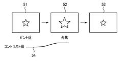
- the digital camera 100 operating in the autofocus mode will be described with reference to FIG.
- the focusing determination unit 112 determines whether or not the focusing lens 131 is focused on the subject based on the received captured image, and focuses the focusing lens 131 on the subject. As the focusing lens 131 focuses on the subject, the sharpness of the captured image increases. Therefore, the enlargement magnification of the enlarged image is gradually increased.
- the enlarged image 51 is an image when the focus of the focusing lens 131 is closer to the digital camera 100 than the subject. In this case, since the subject is out of focus, the subject image is blurred, and the contrast value of the entire image is relatively low.
- the image processing unit 113 enlarges the center of the captured image with a magnification corresponding to a low contrast value, for example, an enlargement magnification of 1.2.
- the enlarged image 51 is obtained as a result.
- the image correction unit 111 does not correct aberration during the focusing operation period. Therefore, a corrected image is not created.
- the LCD 122 receives the enlarged image 51 from the DSP 110 and displays it.
- the enlarged image 52 is an image when the focus is on the subject.
- the subject image is not blurred, and the contrast value of the entire image is a relatively high value.
- the image processing unit 113 creates an enlarged image 52 by enlarging the center of the captured image at a magnification according to the increased contrast value, for example, an enlargement magnification of 1.8 times. That is, since the contrast value of the magnified image 52 is larger than that of the magnified image 51, the size of the subject image included in the magnified image 52 is larger than the subject image in the magnified image 51.
- the LCD 122 displays the enlarged image 52.
- image distortion and blur due to aberrations such as barrel aberration, pincushion aberration, and chromatic aberration hardly occur at the center of a captured image. Therefore, if the image is enlarged around the center of the captured image, the enlarged image is less likely to include distortion and blur due to aberration.
- the DSP 110 does not correct the aberration but uses the calculation capability necessary for correcting the aberration for the image processing. Thereby, the number of photographed images that can be processed per unit time and the resolution of the photographed images can be increased. That is, the resolution and frame rate of the image output from the DSP 110 are improved. Thereby, the LCD 122 can display a moving image having a high resolution and a high frame rate. That is, the user can refer to an image with a high resolution and a high frame rate.
- a change in contrast value of the images shown in the enlarged images 51 and 52 is shown as a curve 54.
- the relationship between the contrast value of the image and the enlargement magnification is stored in the memory 127 as a table.
- the contrast value takes a value from 0 to 255
- the enlargement magnification takes a value from 1 to 4 times.
- the DSP 110 When the DSP 110 receives the half-press signal, the aperture value and the shutter speed are calculated according to the received captured image, and the focus determination unit 112 stops the focus determination and locks the position of the focus lens 131, The correction unit 111 corrects the aberration caused by the focusing lens 131. Then, the image enlargement unit stops creating the enlarged image, and the LCD 122 displays the corrected image 53. Thus, the user can observe an image in which the aberration is corrected and the subject is in focus.
- the DSP 110 receives the half-press signal, the focusing operation period ends. After that, the DSP 110 that has received the full-press signal drives the aperture blade 123 and the shutter curtain 124 with the calculated aperture value and shutter speed, and causes the CMOS 121 to capture a subject image.
- the captured image acquired from the CMOS 121 is subjected to predetermined image processing while using the memory 127 as a temporary storage device, and transmitted to the memory card 128.
- the memory card 128 is an SD card provided so as to be detachable from the digital camera 100, for example, and stores received images.
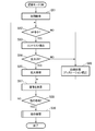
- the second display process will be described with reference to FIG.
- the second display process is a process executed when the digital camera 100 is set to an operation mode for recording an image.
- the digital camera 100 performs autofocus and enlarges a part of the image to the LCD 122. Aberration correction is stopped when this is displayed.
- the contrast value of the entire image is used as the sharpness will be described.
- an initial operation is performed.
- the focusing lens 131 is extended from the body of the digital camera 100, the CMOS 121 starts imaging, and starts to transmit an image to the DSP 110.
- the LCD 122 displays images continuously.
- the DSP 110 reads a table indicating the relationship between the contrast value and the enlargement magnification from the memory 127.
- step S62 it is determined whether or not the digital camera 100 is currently performing autofocus. For example, it is determined that autofocus is currently being performed when the focus determination unit 112 is performing focus determination.
- the process proceeds to step S63, and when not, the process proceeds to step S66.
- step S63 the contrast value of the image is calculated.
- step S64 it is determined whether or not the captured image is enlarged according to the contrast.
- the process proceeds to step S65, and when not enlarging, the process proceeds to step S66.
- step S65 an enlargement magnification is obtained from the table read in step S61 and the contrast value calculated in step S63. Then, the image is enlarged around the center of the image to create an enlarged image. That is, the enlarged image is created during the period when the focus determination unit 112 determines whether or not the subject is in focus and the period during which the display unit displays the enlarged image, that is, the focusing operation period. .
- step S66 the image correcting unit 111 corrects the aberration caused by the focusing lens 131 and creates a corrected image.
- the LCD 122 displays the captured image or the corrected image. That is, when the digital camera 100 is in the focusing operation period, the LCD 122 displays the enlarged images 51 and 52 (see FIG. 5), and when not in the focusing operation period, the LCD 122 displays the correction image 53 (see FIG. 5). To do.
- steps S35 and S36 are the same as the first display process, description thereof will be omitted.
- the LCD 122 when the digital camera 100 is in the focusing operation period, the LCD 122 can display a moving image with a high resolution and a high frame rate. Further, the user can refer to an image with a high resolution and a high frame rate. Furthermore, since a lot of calculation ability can be used for the focus determination, the time required for the focus determination can be shortened. In addition, since it is possible to determine the focus using a high-resolution image, it is possible to determine the focus more accurately.
- the image does not have to be enlarged around the center of the image, and the image may be enlarged around the center of the face detected by the face detection unit 114.
- the number of pixels having a high-frequency component equal to or higher than a predetermined value can be used instead of the above-described contrast value.
- CMOS 121 a solid-state image sensor such as a CCD may be used.
- the contrast value may be obtained by a process other than the process described above.
- the LCD 122 may stop displaying the captured image and display the corrected image.
- the focus may be adjusted by using a switch such as a seesaw switch, dial, or lever instead of the focus adjustment ring 132.
- the DSP 110 may not use the calculation capability necessary for correcting aberrations for image processing. By giving a margin to the processing capacity of the DSP 110, other processing can be executed quickly even when other processing is requested.
- the digital camera 100 may be a so-called compact camera, single-lens reflex camera, or mirrorless single-lens camera.
Landscapes
- Engineering & Computer Science (AREA)
- Multimedia (AREA)
- Signal Processing (AREA)
- Physics & Mathematics (AREA)
- General Physics & Mathematics (AREA)
- Optics & Photonics (AREA)
- Automatic Focus Adjustment (AREA)
- Studio Devices (AREA)
- Focusing (AREA)
- Indication In Cameras, And Counting Of Exposures (AREA)
Abstract
Selon l'invention, lorsqu'un appareil photographique numérique (100) fonctionne dans un mode de mise au point automatique, une unité de détermination de mise au point (112) détermine, sur la base d'une image photographiée, si une lentille de mise au point (131) est ou non mise au point sur un sujet, et amène la lentille de mise au point (131) à se mettre au point sur le sujet. La détermination du point de savoir si le sujet est ou non mis au point est désignée comme détermination de mise au point, et une période pendant laquelle l'unité de détermination de mise au point (112) réalise une détermination de mise au point est désignée comme période d'opération de mise au point. Dans la période d'opération de mise au point, une unité de correction d'image (111) ne crée pas d'image de correction. Un dispositif d'affichage à cristaux liquides (LCD) (122) reçoit une image photographiée à partir d'un DSP (110) et affiche l'image reçue. A cet instant, le DSP (110) utilise, dans un traitement d'image, la puissance de calcul nécessaire pour corriger une aberration. Ceci permet d'augmenter le nombre d'images photographiées pouvant être traitées par unité de temps et la résolution des images photographiées. En d'autres termes, un utilisateur peut voir une image à haute résolution et à fréquence de trames élevée.
Applications Claiming Priority (2)
| Application Number | Priority Date | Filing Date | Title |
|---|---|---|---|
| JP2013-043387 | 2013-03-05 | ||
| JP2013043387A JP2014171203A (ja) | 2013-03-05 | 2013-03-05 | 撮像装置及び画像表示方法 |
Publications (1)
| Publication Number | Publication Date |
|---|---|
| WO2014136703A1 true WO2014136703A1 (fr) | 2014-09-12 |
Family
ID=51491221
Family Applications (1)
| Application Number | Title | Priority Date | Filing Date |
|---|---|---|---|
| PCT/JP2014/055227 Ceased WO2014136703A1 (fr) | 2013-03-05 | 2014-03-03 | Dispositif de capture d'image et procédé d'affichage d'image |
Country Status (2)
| Country | Link |
|---|---|
| JP (1) | JP2014171203A (fr) |
| WO (1) | WO2014136703A1 (fr) |
Families Citing this family (1)
| Publication number | Priority date | Publication date | Assignee | Title |
|---|---|---|---|---|
| CN111698414B (zh) * | 2019-03-14 | 2021-11-16 | 北京小米移动软件有限公司 | 图像信号处理方法及装置、电子设备、可读存储介质 |
Citations (2)
| Publication number | Priority date | Publication date | Assignee | Title |
|---|---|---|---|---|
| JPH11275444A (ja) * | 1998-03-22 | 1999-10-08 | Ricoh Co Ltd | 電子カメラ |
| JP2012199690A (ja) * | 2011-03-18 | 2012-10-18 | Nikon Corp | 撮像装置および撮像装置の制御プログラム |
-
2013
- 2013-03-05 JP JP2013043387A patent/JP2014171203A/ja active Pending
-
2014
- 2014-03-03 WO PCT/JP2014/055227 patent/WO2014136703A1/fr not_active Ceased
Patent Citations (2)
| Publication number | Priority date | Publication date | Assignee | Title |
|---|---|---|---|---|
| JPH11275444A (ja) * | 1998-03-22 | 1999-10-08 | Ricoh Co Ltd | 電子カメラ |
| JP2012199690A (ja) * | 2011-03-18 | 2012-10-18 | Nikon Corp | 撮像装置および撮像装置の制御プログラム |
Also Published As
| Publication number | Publication date |
|---|---|
| JP2014171203A (ja) | 2014-09-18 |
Similar Documents
| Publication | Publication Date | Title |
|---|---|---|
| US8823857B2 (en) | Image apparatus | |
| CN105075240B (zh) | 镜头可换式数码相机 | |
| CN102812714B (zh) | 立体图像获取装置 | |
| US9241109B2 (en) | Image capturing apparatus, control method, and recording medium for moving image generation | |
| JP5864938B2 (ja) | 撮像装置及びその制御方法 | |
| JP4528235B2 (ja) | デジタルカメラ | |
| JP2010268388A (ja) | 撮像装置 | |
| JP2004212556A (ja) | 撮像装置 | |
| JPWO2017154366A1 (ja) | ローパスフィルタ制御装置、およびローパスフィルタ制御方法、ならびに撮像装置 | |
| JP7289055B2 (ja) | 撮像装置 | |
| JP5436116B2 (ja) | 画像処理装置、撮像装置、及び制御方法 | |
| JP5257969B2 (ja) | 合焦位置制御装置、及び合焦位置制御方法、合焦位置制御プログラム | |
| KR100819811B1 (ko) | 촬상 장치 및 촬상 방법 | |
| JP5933306B2 (ja) | 撮像装置 | |
| JP6547742B2 (ja) | 撮像制御装置、撮像装置および撮像制御方法 | |
| WO2014136703A1 (fr) | Dispositif de capture d'image et procédé d'affichage d'image | |
| JP2004287183A (ja) | デジタルカメラ | |
| JP5123010B2 (ja) | 撮像装置、撮像方法及び撮像装置が備えるコンピュータに撮像方法を実行させるためのプログラム | |
| JP2010197524A (ja) | 撮像装置 | |
| JP7307837B2 (ja) | 撮像装置及びその制御方法、プログラム、記憶媒体 | |
| JP2014179782A (ja) | 撮像装置及び画像表示方法 | |
| JP5790011B2 (ja) | 撮像装置 | |
| JP5664440B2 (ja) | 撮像装置 | |
| JP2017058563A (ja) | 自動焦点調節装置、撮像装置、および自動焦点調節方法 | |
| WO2012140919A1 (fr) | Dispositif de génération d'image stéréo et procédé de génération d'image stéréo |
Legal Events
| Date | Code | Title | Description |
|---|---|---|---|
| 121 | Ep: the epo has been informed by wipo that ep was designated in this application |
Ref document number: 14759630 Country of ref document: EP Kind code of ref document: A1 |
|
| NENP | Non-entry into the national phase |
Ref country code: DE |
|
| 122 | Ep: pct application non-entry in european phase |
Ref document number: 14759630 Country of ref document: EP Kind code of ref document: A1 |