WO2014141402A1 - Récipient de toile - Google Patents
Récipient de toile Download PDFInfo
- Publication number
- WO2014141402A1 WO2014141402A1 PCT/JP2013/056963 JP2013056963W WO2014141402A1 WO 2014141402 A1 WO2014141402 A1 WO 2014141402A1 JP 2013056963 W JP2013056963 W JP 2013056963W WO 2014141402 A1 WO2014141402 A1 WO 2014141402A1
- Authority
- WO
- WIPO (PCT)
- Prior art keywords
- cover
- web
- intermediate layer
- opening
- web container
- Prior art date
- Legal status (The legal status is an assumption and is not a legal conclusion. Google has not performed a legal analysis and makes no representation as to the accuracy of the status listed.)
- Ceased
Links
Images

Classifications
-
- B—PERFORMING OPERATIONS; TRANSPORTING
- B65—CONVEYING; PACKING; STORING; HANDLING THIN OR FILAMENTARY MATERIAL
- B65D—CONTAINERS FOR STORAGE OR TRANSPORT OF ARTICLES OR MATERIALS, e.g. BAGS, BARRELS, BOTTLES, BOXES, CANS, CARTONS, CRATES, DRUMS, JARS, TANKS, HOPPERS, FORWARDING CONTAINERS; ACCESSORIES, CLOSURES, OR FITTINGS THEREFOR; PACKAGING ELEMENTS; PACKAGES
- B65D83/00—Containers or packages with special means for dispensing contents
- B65D83/08—Containers or packages with special means for dispensing contents for dispensing thin flat articles in succession
- B65D83/0805—Containers or packages with special means for dispensing contents for dispensing thin flat articles in succession through an aperture in a wall
-
- B—PERFORMING OPERATIONS; TRANSPORTING
- B65—CONVEYING; PACKING; STORING; HANDLING THIN OR FILAMENTARY MATERIAL
- B65D—CONTAINERS FOR STORAGE OR TRANSPORT OF ARTICLES OR MATERIALS, e.g. BAGS, BARRELS, BOTTLES, BOXES, CANS, CARTONS, CRATES, DRUMS, JARS, TANKS, HOPPERS, FORWARDING CONTAINERS; ACCESSORIES, CLOSURES, OR FITTINGS THEREFOR; PACKAGING ELEMENTS; PACKAGES
- B65D77/00—Packages formed by enclosing articles or materials in preformed containers, e.g. boxes, cartons, sacks or bags
- B65D77/04—Articles or materials enclosed in two or more containers disposed one within another
- B65D77/06—Liquids or semi-liquids or other materials or articles enclosed in flexible containers disposed within rigid containers
Definitions
- the present invention relates to a web container.
- the present invention relates to a web container that has an excellent appearance and can be easily manufactured.
- Tissue paper and wet tissue are actively used for home and business use, and their fields of use are expanding.
- Tissue paper is also referred to simply as tissue, is a thin and soft fiber sheet, is a poorly water-soluble daily necessities, is flexible and soft as a material, and is used in various applications.
- the two fiber sheets are combined as a set, and the back surfaces of the two fiber sheets are put out, so that both surfaces are improved in touch and the like.
- a pair of tissue paper is regarded as one sheet.
- wet tissue is made by impregnating a non-woven fabric or other fiber sheet with an impregnating agent such as a drug or cosmetic, and is used for the purpose of removing dirt from the hands, disinfecting or wiping baby's butt.
- Fiber sheets such as tissue paper and wet tissue are collectively referred to as a web.
- tissue paper or wet tissue is folded and stored in a bag formed of a soft film, and one that can be taken out one by one from the opening formed in the bag is used.
- the bag is convenient for carrying, it is easily deformed and has a low stability because it does not have a flat bottom when placed on a table, and its appearance is never good. Therefore, it cannot be said that it is suitable for placing on a table indoors.
- a web container which is a bag body containing the web, is put in a container.
- the container is manufactured so as not to be easily deformed (see, for example, Patent Document 1).
- the container is usually made of plastic, lacks gloss, and is not excellent in appearance. Therefore, for example, it is not very suitable for placing in a room with a guest such as a reception room. Also, it is troublesome for the user to refill the web container into a container after using tissue paper or wet tissue. If the entire container is made disposable, it is convenient for the user. However, with tissue paper and wet tissue, it is also important to keep costs as low as possible.
- an object of the present invention is to provide a web container in which a web container is housed in a container that can be easily manufactured and has an excellent appearance while keeping costs low.
- a web container includes, as shown in FIGS. 1 and 2, for example, a web storage body 60 that stores a folded web 80, and a web storage body 60.
- a web container 10 comprising: a cover 20 made of transparent plastic formed in a polyhedral shape surrounding the cover; and an intermediate layer 40 disposed between the cover 20 and the web container 60;
- a bag body 62 that accommodates the web 80 and includes a bag body 62 in which an opening 64 for taking out the web 80 is formed, and a take-out port member 70 connected to the opening 64.
- the opening 26 to which the outlet member 70 is engaged is formed, and the intermediate layer 40 is formed of a flat sheet and is disposed across at least two adjacent surfaces 22a and 22b of the cover 20. And said that you are.
- the polyhedron shape includes a shape including a curved surface.
- the polyhedral shape includes a case where a ridge line between two surfaces is smoothly formed without being angular.
- the intermediate layer can be seen through the cover of the transparent plastic material and the appearance is excellent, and the intermediate layer extends over at least two surfaces of the cover, so that the ridgeline portion of the surface also passes through the cover made of the transparent plastic material.
- the intermediate layer can be seen, and an excellent appearance can be obtained.
- such a web container can be easily manufactured.
- the web container according to the second aspect of the present invention is the web container according to the first aspect.
- the polyhedron shape is a substantially rectangular parallelepiped shape
- the intermediate layer 40 is continuous with the cover 20. It is arranged across the three surfaces 22b, 22a and 22d.
- the substantially rectangular parallelepiped shape should just have a hexahedron shape generally. The ridgeline between the surfaces may be formed smoothly. Further, the adjacent surfaces do not have to intersect at a right angle.
- the substantially rectangular parallelepiped shape also includes a shape that gradually widens toward the bottom surface (downward in the figure). Further, the substantially rectangular parallelepiped shape includes a shape in which the surface of the cover is not formed on one surface.
- the intermediate layer can be seen through the three continuous surfaces of the cover made of a transparent plastic material, so that it is more aesthetically pleasing and has a substantially rectangular parallelepiped shape. Become. Furthermore, it is easy to accommodate a web storage body having a substantially rectangular parallelepiped shape.
- the web container according to the third aspect of the present invention is the web container according to the second aspect.
- the intermediate layer 40 has an upper surface 22 a on which the opening 26 of the cover 20 is formed, It arrange
- the intermediate layer can be seen through the cover made of a transparent plastic material on the front and both sides. Therefore, it becomes a web container with further excellent appearance.
- the web container according to the fourth aspect of the present invention is the web container according to any one of the first to third aspects.
- a ridge line 24ab between the two surfaces 22a and 22b is formed in a smooth shape without corners.
- the intermediate layer can be seen from the outside even in the ridgeline. Therefore, it becomes a web container with further excellent appearance.
- the web container has an outer appearance in which the intermediate layer disposed between the cover made of a transparent plastic material and the web container is disposed across at least two adjacent surfaces of the cover. Is visible through the cover of transparent plastic material, and is excellent in aesthetics, and since the intermediate layer extends over at least two surfaces of the cover, the intermediate layer can be seen through the cover made of transparent plastic material even at the ridgeline portion of the surface, An excellent appearance can be obtained. Moreover, such a web container can be easily manufactured. As a further effect, it is possible to manufacture web containers with multiple designs, for example, by omitting the printing of product display etc. on covers and bags with complicated shapes and printing designs and information on the intermediate layer. It becomes. Since it is only necessary to mass-produce the web container and cover without changing the mark and change the printing of the intermediate layer, it is very easy to change the design.
- FIG. 1 It is a perspective view explaining the structure of a web container. It is shown with a part cut away so that the inside can be seen. It is sectional drawing explaining the structure of the web container different from FIG. It is a perspective view of a cover. It is a perspective view which shows a coupling member, (a) shows the state which closed the opening-and-closing lid, (b) shows the state which opened the opening-and-closing lid. It is a perspective view which shows the modification of a cover. It is an expanded view of an intermediate
- FIG. 1 is a perspective view illustrating the configuration of the web container 10. It is shown with a part cut away so that the inside can be seen.
- the star which is a design drawn on the mid layer 40, will be visible through the cover 20.
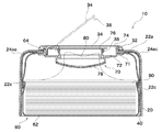
- the web container 10 houses the web container 60 inside the cover 20. That is, the cover 20 surrounds the web storage body 60.
- the cover 20 surrounding the web container 60 includes a case where the cover 20 does not completely cover all directions of the web container 60.
- An intermediate layer 40 is disposed inside the cover 20.
- a coupling member 32 is fixed to the opening 26 of the cover 20.
- the web storage body 60 stores a large number of webs 80 folded in a bag body 62.
- the web 80 may be one in which a continuous long web is continuously stacked in a folded shape or a roll shape, and divided portions are formed at predetermined intervals, and the web 80 is divided and used.
- a bottom cover (not shown) may be attached to the bottom surface (the lower surface in FIG. 1) of the web container 10 in order to prevent the accommodated web storage body 60 from jumping out of the cover 20.
- the bottom lid may be a tape seal or the like.
- FIG. 2 is a cross-sectional view of the web container 10.
- the open / close lid 34 is indicated by a broken line.
- the intermediate layer 40 is also disposed inside the side surfaces 22c and 22e of the cover 20, and the ridgelines 24ac and 24ae are formed smoothly, so that the web container 10 of FIG. And different.
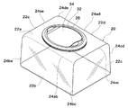
- FIG. 3 is a perspective view of the cover 20.
- FIG. 3 shows a state in which the coupling member 32 and the opening / closing lid 34 are fixed to the cover 20.
- the cover 20 is formed of a transparent plastic material such as polyethylene terephthalate (PET), polycarbonate (PC), polypropylene (PP), polystyrene (PS).
- PET polyethylene terephthalate
- PC polycarbonate
- PP polypropylene
- PS polystyrene
- the transparent plastic material only needs to be visible through the cover 20, and also includes a translucent plastic material in which the interior looks faint.
- the cover 20 is formed in a substantially rectangular parallelepiped shape.
- the cover 20 has an upper surface 22a shown at the top in FIG. 3 and four side surfaces 22b, 22c, 22d, and 22e adjacent to the upper surface 22a.
- the lower part in FIG. 3 facing the upper surface 22a is not formed with a surface and is open.
- 24be is formed in a smooth shape with no corners or irregularities.
- the smooth shape is a rounded shape with no corners or irregularities, and its curvature radius is about 1 to 50 mm, preferably about 2 to 20 mm. If the curvature radius is too small, the intermediate layer 40 becomes difficult to be disposed along the cover 20 and wrinkles are likely to occur. Conversely, if the radius of curvature is too large, it will be difficult to accommodate the web container 60.
- the smooth shape may be a relaxed curve shape in which the radius of curvature becomes large at the portions in contact with both surfaces of the ridgeline, and the minimum value of the radius of curvature is preferably in the above range. Further, the four side surfaces 22b, 22c, 22d, and 22e are formed so as to gradually widen with distance from the upper surface 22a.
- the substantially rectangular parallelepiped shape includes a shape in which the surface of the cover 20 is not formed on one surface. Further, the substantially rectangular parallelepiped shape includes a shape in which a ridge line between surfaces is smoothly formed. Furthermore, the substantially rectangular parallelepiped shape includes a shape in which adjacent surfaces are not orthogonal to each other. An opening other than the opening 26 at the top may be formed on the surface. Moreover, the opening (not shown) etc. which insert the intermediate
- FIG. 1 an open / close lid 34 for taking out the web is disposed on the upper surface of the web container 10.
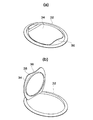
- 4A and 4B are perspective views showing the opening / closing lid 34 formed integrally with the coupling member 32, wherein FIG. 4A shows a state in which the opening / closing lid 34 is closed, and FIG. 4B shows a state in which the opening / closing lid 34 is opened.
- the coupling member 32 is a member that is coupled to the take-out port member 70 and sandwiches the cover 20 to fix the cover 20. As will be described later, the coupling member 32 is coupled to the take-out port member 70 of the web storage body 60 with the cover 20 interposed therebetween, thereby fixing the web storage body in a state suspended from the opening 26 of the cover 20.
- the coupling member 32 is required to have high rigidity because a large force acts when the opening / closing lid 34 is opened / closed. Further, the joint portion between the coupling member 32 and the opening / closing lid 34 needs to be elastically deformed. Therefore, it is formed relatively thick using a plastic material such as polyethylene (PE) or polypropylene (PP).
- PE polyethylene
- PP polypropylene
- a web 80 is folded in the web storage body 60 and stored in a bag body 62 formed of a soft film or the like.
- the web 80 is a sheet formed from a fiber such as a nonwoven fabric. Tissue paper and wet tissue are typical, but not limited thereto.
- the web container 60 is generally shaped like a rectangular parallelepiped because the rectangular web 80 is folded and housed inside. However, in manufacturing the bag body 62, overhangs for crimping after the web 80 is stored in the bag body 62 are often formed on both sides.
- the bag body 62 is not limited to this, and may have any structure.
- an opening 64 for taking out the web 80 from the bag body 62 is formed in the bag body 62.
- a takeout port member 70 is disposed in the opening 64 of the web storage body 60.
- the outer periphery 71 of the outlet member 70 is in close contact with the bag body 62 around the opening 64.
- the outer periphery 71 may be welded or adhered to the bag body 62. Any method may be used as long as the outlet port member 70 can be connected to the opening 64 of the bag body 62.
- the bag body 62 is bonded to the upper surface of the outer periphery 71 of the take-out port member 70, but may be bonded to the lower surface of the outer periphery 71.
- the central portion of the take-out port member 70 is a path for taking out the web 80.
- a resistance imparting plate 78 is provided at the lowermost portion, and small holes are provided to provide resistance in order to prevent the plurality of webs 80 from being taken out while being connected.
- the upper portion of the resistance applying plate 78 is a space for storing the tip of the popped up web. Since the tip of the web 80 is held in the small hole of the resistance imparting plate 78, it becomes easy to grip the tip of the web 80 next.
- the opening / closing lid receiving portion 76 at the uppermost center of the outlet port member 70, that is, the upper part of the storage space at the tip of the web, and a concave groove formed in the opening / closing lid receiving portion 76, which is the outer periphery of the cylindrical opening / closing lid receiving portion 76. It fits with the ridge of the closing member 38.
- the web container 10 is sealed after use by such a fitting mechanism, and the web 80 is preferably prevented from drying.
- the hinge portion of the opening / closing lid 34 is formed integrally with the coupling member 32, but the opening / closing lid 34 may be formed integrally with a later-described outlet member 70 or may be a completely independent part. Is possible.
- the web container 60 can be sealed by other structures such as an adhesive seal.
- a seal with a tab (not shown) is disposed between the opening / closing lid receiving portion 76 and the resistance imparting plate 78 so that the web container 60 is sealed with the seal before use of the web container 10. Also good.
- the seal can be easily removed by pulling the tab during use.
- a protrusion is formed on the upper outer edge 74 of the outlet member 70, and the protrusion is fitted with a groove formed on the inner periphery of the coupling member 32. In this manner, the takeout port member 70 engages with the coupling member 32 and holds the opening portion 26 of the cover 20 across the opening portion 26.
- the web container 60 is suspended from the cover 20 via the takeout port member 70. Therefore, even if the remaining amount of the web 80 is reduced and the bag body 62 is crushed, the opening 64 for removing the web 80 from the bag body 62 does not leave the opening 26 of the cover 20. Therefore, it is always easy to take out the web 80 from the opening 26.
- FIG. 2 there is a large gap between the take-out port member 70 and the cover 20, but this is to make the drawing easier to see. There may be no gap or a small gap.
- the extraction port member 70 is formed using a plastic material such as polyethylene (PE) or polypropylene (PP).
- PE polyethylene
- PP polypropylene
- the configuration of the take-out port member 70 is not limited to the configuration shown in FIG. 2, and other configurations may be used. For example, instead of being coupled to the coupling member 32, it may be engaged with the opening 26 of the cover 20 by fitting into the opening 26 of the cover 20 or by being bonded to the cover 20. Further, the opening / closing lid 34 may be connected to the take-out port member 70 via a joint portion.
- the cover 20 has been described as having a substantially rectangular parallelepiped shape.
- the shape of the cover 20 is not limited to a substantially rectangular parallelepiped shape.
- the shape of the cover 20 may be a polyhedron.
- the surface of the polyhedron may include a curved surface.
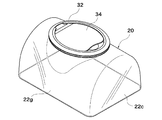
- the upper surface 22a is formed as a curved surface
- the side surface 22b, the upper surface 22a, and the side surface 22d are one surface 22g. It may be formed in a kamaboko shape.
- the thickness of the coupling member 32 may be adjusted to be along the curved surface 22g, or the coupling member 32 may be formed in a curved shape along the curved surface 22g.
- the outlet member 70 is formed in accordance with the shape of the coupling member 32.
- the coupling member 32 and the takeout port member 70 are coupled with the upper surface 22a of the cover 20 interposed therebetween.
- the intermediate layer 40 may be disposed only in a portion corresponding to the surface 22g.
- the intermediate layer 40 may not be disposed on the entire surface of the cover 20.
- the cover 20 may be formed in, for example, a substantially octahedral shape in which the side surface 22b and the side surface 22d shown in FIG. 3 are each formed of two surfaces.
- the ridge lines 24ab, 24ac, 24ad, and 24ae surrounding the upper surface 22a of the cover 20 are formed smoothly, and the ridge lines 24ac and 24ae are formed in an angular shape. In this way, only the portions 22ab and 22ad of the ridgeline may be formed smoothly.
- the ridgelines 24ac, 24ae, 24bc see FIG. 3
- 24cd, 24ae, and 24be surrounding the side surfaces 22c and 22e are squared
- the side surfaces 22c and 22e are faced down. Stability is improved. That is, even when the opening 26 of the cover 26 is turned sideways, the web container 10 is easy to use.
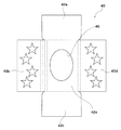
- FIG. 6 is a development view of the intermediate layer 40 before being placed in the cover 20, and a broken line indicates a portion that bends when placed in the cover 20.
- the intermediate layer 40 is formed in a planar shape.
- the term “plane” as used herein means a plane before being inserted into the cover 20, and includes a material that is wound around a roll as a material and has a three-dimensional shape after being placed in the cover 20.
- the material may be printed on a transparent plastic film such as unstretched polypropylene (CPP), polyethylene (PE), polyethylene terephthalate (PET), or paper, and is not particularly limited.
- a transparent plastic film of about 0.05 mm to 0.2 mm is used.
- When printing on a transparent plastic film it may be printed on the cover 20 side or on the back side.
- an asterisk is drawn as a design.
- One flat intermediate layer 40 is formed around the portion 42a corresponding to the upper surface 22a of the cover 20 and portions 42b, 42c, 42d and 42e corresponding to the four side surfaces 22b, 22c, 22d and 22e. Is formed.
- an opening 46 is formed at a location corresponding to the opening 26 of the cover 20.
- the opening 46 may be formed larger than the opening 26 of the cover 20 or may have the same size. By forming the opening 46 larger than the opening 26, the intermediate layer 40 is not sandwiched between the cover 20 and the outlet member 70.
- the web container 10 shown in FIG. 1 omits the intermediate layer along the side surface 22c of the cover 20, but the intermediate layer 40 shown in FIG.
- the cover 6 has a shape suitable for the cover 20 shown in FIG.
- the portion 42a corresponding to the upper surface 22a of the cover 20 and the portions 42b and 42d corresponding to the two side surfaces 22b and 22d it bends with a large radius of curvature in accordance with the smoothly shaped ridge lines 42ab and 42ad.
- the bent portion is indicated by a plurality of broken lines.
- the outer edges corresponding to the ridge lines 42ab and 42ad are formed in a curved shape matching a large curvature radius.
- the intermediate layer 40 shown in FIG. 6 can be disposed on the five surfaces of the cover 20 shown in FIG.
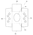
- FIG. 7 is a development view of the intermediate layer 40 before being placed in the cover 20 similar to FIG. In FIG. 7, a star is drawn as a design.
- the intermediate layer 40 shown in FIG. 7 has a shape suitable for the web container 10 shown in FIG.
- the portions 42b and 42d of the intermediate layer 40 corresponding to the side surfaces 22b and 22d are provided with overhangs that overlap the portions 42c and 42e, thereby preventing a gap between the intermediate layers 40 when formed in the cover 20.
- the intermediate layer 40 is not limited to the one shown in FIG. 6 or 7 and is formed in a shape corresponding to the shape of the cover 20. Further, the intermediate layer 40 may be used by combining two or more intermediate layer portions. However, in the case of the web container 10 shown in FIG. 1, the intermediate layer can be easily formed by forming the shape as shown in FIG. 6 and in the case of the web container 10 shown in FIG. 40 can be arranged at a predetermined position in the cover 20. That is, after the intermediate layer 40 is disposed in the lower portion where the surface of the cover 20 is not formed, the web container 60 is accommodated in the cover 20 so as to push the intermediate layer 40 into the cover 20.
- the intermediate layer 40 can be disposed at a predetermined position by being sandwiched between the cover 20 and the web container 60.
- the intermediate layer 40 may be adhered to the cover 20 or the web container 60.
- the take-out port member 70 and the coupling member 32 or the take-out port member 70 and the cover 20 may be sandwiched and arranged at a predetermined position.
- middle layer which is not provided with the part 42c * 42e of the intermediate
- the intermediate layer 40 can also be formed from a single rectangular sheet, which facilitates manufacture.
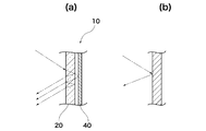
- FIG. 8 is a partial cross-sectional view for explaining the external appearance of the web container 10.
- FIG. 8A shows a light reflection state when the light strikes the web container 10 according to the present invention, and FIG. The light reflection state when light hits the web container is shown.
- FIG. 8A there is a large gap between the cover 20 and the intermediate layer 40, but this is to make the drawing easier to see. There may be no gap or a small gap.
- FIG.8 (b) even if light strikes, only the reflected light on the surface is visible.
- FIG. 8 shows a small gap between the cover 20 and the intermediate layer 40
- the cover 20 is transparent, so that light enters the cover 20. Part of the light that has entered the wall of the cover 20 is reflected by the back surface, and the rest is transmitted. The light transmitted through the cover 20 is reflected by the intermediate layer 40. The light reflected by the intermediate layer 40 is transmitted through the cover 20 or is repeatedly reflected and then finally transmitted through the cover 20. In the web container 10, the light reflected by the intermediate layer 40 is reflected on both the front and back surfaces of the cover 20. By mixing the reflected light reflected from various surfaces, it looks like a gentle image for the observer, and an excellent aesthetic appearance is obtained. As a result, the web container 10 having an excellent appearance is obtained.
- the intermediate layer 40 has a metallic luster as in the case where the transparent film is colored by aluminum vapor deposition, more intense reflections are repeated until the printed surface reaches the eyes of the observer. It seems to have a gentle and beautiful gloss. As a result, it is extremely aesthetically pleasing.
- the intermediate layer 40 extends over at least two adjacent surfaces of the cover 20, it appears as a gentle image to the observer even on the two ridge lines.
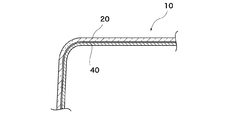
- the intermediate layer 40 is easily arranged along the ridgeline. Further, the intermediate layer 40 is preferably not wrinkled, which is preferable.
- the intermediate layer 40 when the intermediate layer 40 is pressed against the cover 20 with a strong force and closely contacts, the light reflectance of that portion changes. In that case, only that part looks different from the surroundings, which is not preferable. Further, even if liquid or the like adheres between the cover 20 and the intermediate layer 40, the reflectance changes only at that portion and affects the appearance, which is not preferable.
- the intermediate layer 40 looks more complicated and three-dimensional due to the lens effect.
- the inner surface (the side where the intermediate layer 40 is disposed) of the cover 20 may be formed so as to wave, or unevenness may be provided.
- the conventional web container for example, vapor-deposits aluminum for each container, which requires a large vapor deposition apparatus, and requires a great deal of cost.
- the web container 10 only the flat intermediate layer 40 needs to be vapor-deposited with aluminum. Therefore, significant cost reduction can be achieved. Furthermore, the appearance design of the web container 10 or the web product with the container can be changed simply by replacing the intermediate layer 40, which is practically beneficial.
- the cover 20 can be formed thinner than the coupling member 32.
- the thickness is 0.2 to 2 mm, more preferably 0.3 to 1 mm. Therefore, the manufacturing cost of the cover 20 can be reduced, and the web container 10 can be reduced in weight.
- the web container 10 of the present invention is excellent in appearance, can be easily manufactured, and can be kept at a low cost. You may block
Landscapes
- Engineering & Computer Science (AREA)
- Mechanical Engineering (AREA)
- Packages (AREA)
- Containers And Packaging Bodies Having A Special Means To Remove Contents (AREA)
Abstract
Le problème de l'invention consiste à proposer un récipient de toile dont les coûts sont réduits et qui possède un excellent aspect. La solution proposée par l'invention concerne un récipient de toile (10) comprenant : un corps de stockage de toile (60) dans lequel une toile repliée (80) est stockée ; un couvercle en plastique transparent (20) formé de façon à avoir une forme de polyèdre qui entoure le corps de stockage de toile (60) ; et une couche intermédiaire (40) disposée entre le couvercle (20) et le corps de stockage de toile (60). Le corps de stockage de toile (60) comprend : un corps de sac (62) dans lequel la toile (80) est stockée et dans lequel une ouverture (64) est ménagée pour extraire la toile (80) ; et un élément d'orifice d'extraction (70) raccordé à l'ouverture (64). Une ouverture (26) à laquelle l'élément d'orifice d'extraction (70) est joint est formée dans une surface du couvercle (20). La couche intermédiaire (40) est formée à partir d'une feuille plate et est disposée de façon à s'étendre sur au moins deux surfaces adjacentes (22a, 22b) du couvercle (20).
Priority Applications (3)
| Application Number | Priority Date | Filing Date | Title |
|---|---|---|---|
| PCT/JP2013/056963 WO2014141402A1 (fr) | 2013-03-13 | 2013-03-13 | Récipient de toile |
| JP2014546640A JP5883947B2 (ja) | 2013-03-13 | 2013-03-13 | ウェブ容器 |
| US14/166,746 US9302843B2 (en) | 2013-03-13 | 2014-01-28 | Web container |
Applications Claiming Priority (1)
| Application Number | Priority Date | Filing Date | Title |
|---|---|---|---|
| PCT/JP2013/056963 WO2014141402A1 (fr) | 2013-03-13 | 2013-03-13 | Récipient de toile |
Related Child Applications (1)
| Application Number | Title | Priority Date | Filing Date |
|---|---|---|---|
| US14/166,746 Continuation US9302843B2 (en) | 2013-03-13 | 2014-01-28 | Web container |
Publications (1)
| Publication Number | Publication Date |
|---|---|
| WO2014141402A1 true WO2014141402A1 (fr) | 2014-09-18 |
Family
ID=51522679
Family Applications (1)
| Application Number | Title | Priority Date | Filing Date |
|---|---|---|---|
| PCT/JP2013/056963 Ceased WO2014141402A1 (fr) | 2013-03-13 | 2013-03-13 | Récipient de toile |
Country Status (3)
| Country | Link |
|---|---|
| US (1) | US9302843B2 (fr) |
| JP (1) | JP5883947B2 (fr) |
| WO (1) | WO2014141402A1 (fr) |
Families Citing this family (1)
| Publication number | Priority date | Publication date | Assignee | Title |
|---|---|---|---|---|
| HU1500017V0 (hu) * | 2015-02-17 | 2017-08-28 | Vajda Papir Kft | Tartóeszközhöz rögzíthetõ csomagolás háztartási és higiéniai papírokhoz |
Citations (8)
| Publication number | Priority date | Publication date | Assignee | Title |
|---|---|---|---|---|
| JPH0299792U (fr) * | 1989-01-25 | 1990-08-08 | ||
| JP3029550U (ja) * | 1996-03-28 | 1996-10-01 | 多市郎 奥村 | ティシュボックス |
| JPH0986584A (ja) * | 1995-09-25 | 1997-03-31 | Mitsunobu Negishi | 輸入cd |
| JPH09132280A (ja) * | 1995-11-08 | 1997-05-20 | Uni Charm Corp | 濡れナプキン収納容器 |
| JP2001046275A (ja) * | 1999-08-04 | 2001-02-20 | Daiichi Shiko Kk | ウエットティッシュ装置 |
| JP3138354U (ja) * | 2007-10-17 | 2007-12-27 | 株式会社資生堂 | ティッシュボックス用の被せ型popカバー |
| JP2009132432A (ja) * | 2007-11-30 | 2009-06-18 | Daio Paper Corp | 衛生薄葉紙製品包装体 |
| WO2012070230A1 (fr) * | 2010-11-25 | 2012-05-31 | Yamada Kikuo | Corps d'emballage de lingettes humides |
Family Cites Families (7)
| Publication number | Priority date | Publication date | Assignee | Title |
|---|---|---|---|---|
| US6213300B1 (en) * | 1999-07-20 | 2001-04-10 | Unilever Home & Personal Care Usa, Division Of Conopco,Inc. | Refillable towelette dispensing package |
| JP4791111B2 (ja) * | 2004-09-22 | 2011-10-12 | ユニ・チャーム株式会社 | ティッシュ繰り出し容器 |
| ES2324045T3 (es) * | 2005-04-27 | 2009-07-29 | THE PROCTER & GAMBLE COMPANY | Recipiente para toallitas humedas y envase de repuesto con seguro de compatibilidad y accionador de compatibilidad. |
| US20070284266A1 (en) * | 2006-06-13 | 2007-12-13 | Kimberly-Clark Worldwide, Inc. | Container or dispenser with a decorative sleeve |
| JP5160195B2 (ja) * | 2007-11-02 | 2013-03-13 | 株式会社フジシールインターナショナル | ウェットシート軟包体、及び該軟包体用ラベル |
| US8245876B2 (en) * | 2009-07-15 | 2012-08-21 | The Procter & Gamble Company | Wipes container |
| JP5078105B2 (ja) | 2011-06-06 | 2012-11-21 | ユニ・チャーム株式会社 | 蓋付き容器 |
-
2013
- 2013-03-13 WO PCT/JP2013/056963 patent/WO2014141402A1/fr not_active Ceased
- 2013-03-13 JP JP2014546640A patent/JP5883947B2/ja not_active Expired - Fee Related
-
2014
- 2014-01-28 US US14/166,746 patent/US9302843B2/en not_active Expired - Fee Related
Patent Citations (8)
| Publication number | Priority date | Publication date | Assignee | Title |
|---|---|---|---|---|
| JPH0299792U (fr) * | 1989-01-25 | 1990-08-08 | ||
| JPH0986584A (ja) * | 1995-09-25 | 1997-03-31 | Mitsunobu Negishi | 輸入cd |
| JPH09132280A (ja) * | 1995-11-08 | 1997-05-20 | Uni Charm Corp | 濡れナプキン収納容器 |
| JP3029550U (ja) * | 1996-03-28 | 1996-10-01 | 多市郎 奥村 | ティシュボックス |
| JP2001046275A (ja) * | 1999-08-04 | 2001-02-20 | Daiichi Shiko Kk | ウエットティッシュ装置 |
| JP3138354U (ja) * | 2007-10-17 | 2007-12-27 | 株式会社資生堂 | ティッシュボックス用の被せ型popカバー |
| JP2009132432A (ja) * | 2007-11-30 | 2009-06-18 | Daio Paper Corp | 衛生薄葉紙製品包装体 |
| WO2012070230A1 (fr) * | 2010-11-25 | 2012-05-31 | Yamada Kikuo | Corps d'emballage de lingettes humides |
Also Published As
| Publication number | Publication date |
|---|---|
| JP5883947B2 (ja) | 2016-03-15 |
| JPWO2014141402A1 (ja) | 2017-02-16 |
| US20140262908A1 (en) | 2014-09-18 |
| US9302843B2 (en) | 2016-04-05 |
Similar Documents
| Publication | Publication Date | Title |
|---|---|---|
| CN102905992B (zh) | 钮扣电池分配封装件 | |
| US6959834B2 (en) | Windowless tissue carton | |
| WO2013132782A1 (fr) | Unité d'emballage de tissus humides | |
| WO2013024566A1 (fr) | Emballage de lingettes humides | |
| JP2022191177A (ja) | 蓋体、容器と蓋体の組み合わせ、及び蓋体付き容器 | |
| JP5883947B2 (ja) | ウェブ容器 | |
| KR102112238B1 (ko) | 일체형 베이스 필름을 통한 재점착 라벨 구조 | |
| WO2014104216A1 (fr) | Corps d'emballage de tissus humides | |
| JP2009280240A (ja) | 紙製容器 | |
| WO2024031668A1 (fr) | Boîte d'emballage | |
| JP2013047120A (ja) | 包装ケース | |
| JP2022065417A (ja) | シート収納容器 | |
| JP4577767B2 (ja) | ブリスターパック | |
| KR200462085Y1 (ko) | 윈도우를 갖는 포장 용기 | |
| JP5946267B2 (ja) | 包装体 | |
| JP2011173642A (ja) | 包装用ケース | |
| KR20180087622A (ko) | 거울기능을 갖는 파우치 | |
| JP3228479U (ja) | 食品包装用容器 | |
| JP3160076U (ja) | 収納容器 | |
| KR20110030019A (ko) | 계단형 샌드위치 포장용기 | |
| JP7334600B2 (ja) | 包装体 | |
| JP3153764U (ja) | 流動体収容袋の収納用ダンボール箱 | |
| JP2016052909A (ja) | 容器 | |
| JP2010001050A (ja) | 包装ケース | |
| JP6725630B2 (ja) | ケース |
Legal Events
| Date | Code | Title | Description |
|---|---|---|---|
| ENP | Entry into the national phase |
Ref document number: 2014546640 Country of ref document: JP Kind code of ref document: A |
|
| 121 | Ep: the epo has been informed by wipo that ep was designated in this application |
Ref document number: 13878369 Country of ref document: EP Kind code of ref document: A1 |
|
| NENP | Non-entry into the national phase |
Ref country code: DE |
|
| 122 | Ep: pct application non-entry in european phase |
Ref document number: 13878369 Country of ref document: EP Kind code of ref document: A1 |