WO2014141486A1 - Appareil de source d'alimentation sans coupure - Google Patents
Appareil de source d'alimentation sans coupure Download PDFInfo
- Publication number
- WO2014141486A1 WO2014141486A1 PCT/JP2013/057560 JP2013057560W WO2014141486A1 WO 2014141486 A1 WO2014141486 A1 WO 2014141486A1 JP 2013057560 W JP2013057560 W JP 2013057560W WO 2014141486 A1 WO2014141486 A1 WO 2014141486A1
- Authority
- WO
- WIPO (PCT)
- Prior art keywords
- power supply
- unit
- battery
- power
- supply unit
- Prior art date
- Legal status (The legal status is an assumption and is not a legal conclusion. Google has not performed a legal analysis and makes no representation as to the accuracy of the status listed.)
- Ceased
Links
Images





Classifications
-
- H—ELECTRICITY
- H02—GENERATION; CONVERSION OR DISTRIBUTION OF ELECTRIC POWER
- H02J—ELECTRIC POWER NETWORKS; CIRCUIT ARRANGEMENTS OR SYSTEMS FOR SUPPLYING OR DISTRIBUTING ELECTRIC POWER; SYSTEMS FOR STORING ELECTRIC ENERGY
- H02J1/00—Circuit arrangements for DC mains or DC distribution networks
- H02J1/08—Three-wire DC power distribution systems; Systems having more than three wires
-
- H—ELECTRICITY
- H02—GENERATION; CONVERSION OR DISTRIBUTION OF ELECTRIC POWER
- H02J—ELECTRIC POWER NETWORKS; CIRCUIT ARRANGEMENTS OR SYSTEMS FOR SUPPLYING OR DISTRIBUTING ELECTRIC POWER; SYSTEMS FOR STORING ELECTRIC ENERGY
- H02J1/00—Circuit arrangements for DC mains or DC distribution networks
- H02J1/10—Parallel operation of DC sources
- H02J1/102—Parallel operation of DC sources being switching converters
-
- H—ELECTRICITY
- H02—GENERATION; CONVERSION OR DISTRIBUTION OF ELECTRIC POWER
- H02J—ELECTRIC POWER NETWORKS; CIRCUIT ARRANGEMENTS OR SYSTEMS FOR SUPPLYING OR DISTRIBUTING ELECTRIC POWER; SYSTEMS FOR STORING ELECTRIC ENERGY
- H02J7/00—Circuit arrangements for charging or discharging batteries or for supplying loads from batteries
- H02J7/34—Parallel operation in networks using both storage and other DC sources, e.g. providing buffering
-
- H—ELECTRICITY
- H02—GENERATION; CONVERSION OR DISTRIBUTION OF ELECTRIC POWER
- H02J—ELECTRIC POWER NETWORKS; CIRCUIT ARRANGEMENTS OR SYSTEMS FOR SUPPLYING OR DISTRIBUTING ELECTRIC POWER; SYSTEMS FOR STORING ELECTRIC ENERGY
- H02J7/00—Circuit arrangements for charging or discharging batteries or for supplying loads from batteries
- H02J7/34—Parallel operation in networks using both storage and other DC sources, e.g. providing buffering
- H02J7/345—Parallel operation in networks using both storage and other DC sources, e.g. providing buffering using capacitors as storage or buffering devices
-
- H—ELECTRICITY
- H02—GENERATION; CONVERSION OR DISTRIBUTION OF ELECTRIC POWER
- H02J—ELECTRIC POWER NETWORKS; CIRCUIT ARRANGEMENTS OR SYSTEMS FOR SUPPLYING OR DISTRIBUTING ELECTRIC POWER; SYSTEMS FOR STORING ELECTRIC ENERGY
- H02J7/00—Circuit arrangements for charging or discharging batteries or for supplying loads from batteries
- H02J7/34—Parallel operation in networks using both storage and other DC sources, e.g. providing buffering
- H02J7/35—Parallel operation in networks using both storage and other DC sources, e.g. providing buffering with light sensitive cells
-
- H—ELECTRICITY
- H02—GENERATION; CONVERSION OR DISTRIBUTION OF ELECTRIC POWER
- H02J—ELECTRIC POWER NETWORKS; CIRCUIT ARRANGEMENTS OR SYSTEMS FOR SUPPLYING OR DISTRIBUTING ELECTRIC POWER; SYSTEMS FOR STORING ELECTRIC ENERGY
- H02J9/00—Circuit arrangements for emergency or stand-by power supply, e.g. for emergency lighting
- H02J9/04—Circuit arrangements for emergency or stand-by power supply, e.g. for emergency lighting in which the distribution system is disconnected from the normal source and connected to a standby source
- H02J9/06—Circuit arrangements for emergency or stand-by power supply, e.g. for emergency lighting in which the distribution system is disconnected from the normal source and connected to a standby source with automatic change-over, e.g. UPS systems
- H02J9/062—Circuit arrangements for emergency or stand-by power supply, e.g. for emergency lighting in which the distribution system is disconnected from the normal source and connected to a standby source with automatic change-over, e.g. UPS systems for AC powered loads
-
- H—ELECTRICITY
- H02—GENERATION; CONVERSION OR DISTRIBUTION OF ELECTRIC POWER
- H02J—ELECTRIC POWER NETWORKS; CIRCUIT ARRANGEMENTS OR SYSTEMS FOR SUPPLYING OR DISTRIBUTING ELECTRIC POWER; SYSTEMS FOR STORING ELECTRIC ENERGY
- H02J2101/00—Supply or distribution of decentralised, dispersed or local electric power generation
- H02J2101/20—Dispersed power generation using renewable energy sources
- H02J2101/28—Wind energy
-
- Y—GENERAL TAGGING OF NEW TECHNOLOGICAL DEVELOPMENTS; GENERAL TAGGING OF CROSS-SECTIONAL TECHNOLOGIES SPANNING OVER SEVERAL SECTIONS OF THE IPC; TECHNICAL SUBJECTS COVERED BY FORMER USPC CROSS-REFERENCE ART COLLECTIONS [XRACs] AND DIGESTS
- Y02—TECHNOLOGIES OR APPLICATIONS FOR MITIGATION OR ADAPTATION AGAINST CLIMATE CHANGE
- Y02B—CLIMATE CHANGE MITIGATION TECHNOLOGIES RELATED TO BUILDINGS, e.g. HOUSING, HOUSE APPLIANCES OR RELATED END-USER APPLICATIONS
- Y02B10/00—Integration of renewable energy sources in buildings
- Y02B10/70—Hybrid systems, e.g. uninterruptible or back-up power supplies integrating renewable energies
-
- Y—GENERAL TAGGING OF NEW TECHNOLOGICAL DEVELOPMENTS; GENERAL TAGGING OF CROSS-SECTIONAL TECHNOLOGIES SPANNING OVER SEVERAL SECTIONS OF THE IPC; TECHNICAL SUBJECTS COVERED BY FORMER USPC CROSS-REFERENCE ART COLLECTIONS [XRACs] AND DIGESTS
- Y02—TECHNOLOGIES OR APPLICATIONS FOR MITIGATION OR ADAPTATION AGAINST CLIMATE CHANGE
- Y02E—REDUCTION OF GREENHOUSE GAS [GHG] EMISSIONS, RELATED TO ENERGY GENERATION, TRANSMISSION OR DISTRIBUTION
- Y02E10/00—Energy generation through renewable energy sources
- Y02E10/70—Wind energy
- Y02E10/76—Power conversion electric or electronic aspects
Definitions
- the present invention relates to an uninterruptible power supply apparatus that can be constructed in a space-saving manner, for example, in a power supply system that is installed in a data center and supplies power to a plurality of servers (load devices) that constitute a multi-node server.
- FIG. 12 is a schematic configuration diagram of a conventional general power supply system in a data center including a plurality of load devices using a DC voltage as a driving power source, for example, a plurality of servers.
- This power supply system includes an uninterruptible power supply (UPS) 1 interposed in a 400V system power supply and high-voltage AC power (AC400V) fed via the uninterruptible power supply 1, for example, 200V or And an AC power supply distributor (PDU) 2 for converting into 100V AC power.
- UPS uninterruptible power supply
- AC400V high-voltage AC power
- PDU AC power supply distributor
- the uninterruptible power supply 1 basically includes a large capacity battery (BAT) 1a capable of storing DC power.
- the uninterruptible power supply 1 includes an AC / DC converter 1b that converts the high-voltage AC power into a DC voltage to charge the battery 1a, an output voltage of the AC / DC converter 1b, or the battery 1a. And a DC / AC converter 1c that converts the DC power stored in the battery into high-voltage AC power and outputs it.
- the power distribution unit 2 includes a circuit breaker 2a that separates, for example, the system power supply and the load facility side including the load device (server).
- the AC power supply distributor 2 further includes a transformer 2b that converts the high-voltage AC power (AC 400V) into, for example, 200V AC power and outputs it.
- reference numeral 3 denotes a transformer which converts, for example, 6.6 kV transmission AC power into the high-voltage AC power (AC 400 V) and draws it into the building where the uninterruptible power supply 1 and the like are provided.
- the load equipment constructed by including a plurality of servers 4 as the load devices is connected to the power supply distributor 2 at the front stage thereof, and is the drive power supply voltage of the server 4 from the AC power (AC200V).
- a switching power supply 5 that generates low-voltage direct current power (for example, DC12V) of 48V or less is provided.
- the switching power supply 5 generally includes an AC / DC converter 5a that converts the AC power (AC 200V) into a DC voltage, and a DC output voltage that supplies the output voltage of the AC / DC converter 5a to the server 4. And a DC / DC converter 5b for conversion to (DC12V).
- the plurality of servers 4 are respectively connected to the switching power supply 5 and are operated by being supplied with the DC output voltage, which is a driving power supply for the server 4, from the switching power supply 5 (see, for example, Patent Document 1).
- the plurality of servers 4 are generally installed in a server rack by storing a predetermined number of servers 4 so as to form a server group, and the switching power supply 5 is provided corresponding to each server group.
- the switching power supply 5 is housed in the server rack together with the predetermined number of servers 4.
- the conventional general power supply system configured as described above has a large number of conversion stages such as the AC / DC converters 1b and 5a and the DC / DC converter 5b described above, and conversion efficiency with respect to power is poor. Therefore, a power supply system in which a DC power supply system as shown in FIGS. 13 and 14 is constructed has been proposed.
- the power supply system shown in FIG. 13 directly feeds the high-voltage DC power (DC 400V) obtained from the AC / DC converter 1b of the uninterruptible power supply 1 to the DC power supply distributor 2.
- the high-voltage direct current power fed through the power distributor 2a is input to a switching power source 5 including a DC / DC converter 5d, and the switching power source 5 (DC / DC converter 5d) is input.
- DC 12 V DC output voltage
- This type of power supply system is called, for example, a high-voltage DC power supply system (HVCD) (see, for example, Non-Patent Document 1).
- HVCD high-voltage DC power supply system
- the power supply system shown in FIG. 14 uses high voltage direct current power (DC400V) obtained from the AC / DC converter 1b of the uninterruptible power supply 1 as a DC / DC converter 1d provided in the uninterruptible power supply 1. Then, the power is converted to a low DC voltage (DC48V) and supplied to the DC power supply distributor 2a. On the load device side, the DC low voltage fed from the power supply distributor 2a is input to the switching power supply 5 including the DC / DC converter 5e, and the switching power supply 5 (DC / DC converter 5e) The server 4 is configured to generate a DC output voltage (DC 12 V) that supplies power to each server 4.
- This type of power supply system is called, for example, a low-voltage DC power supply system (see, for example, Non-Patent Document 2).
- Patent Document 2 discloses that the uninterruptible power supply is operated in parallel.
- Patent Document 3 discloses that when the number of parallel operations of the uninterruptible power supply apparatus is increased, only the batteries are connected in parallel by switching the switch, thereby changing the battery capacity.
- the present invention has been made in consideration of such circumstances, and an object of the present invention is, for example, to provide a power supply system that supplies power to a load device composed of a plurality of servers in a compact and space-saving manner, and to achieve a required power capacity.
- An object of the present invention is to provide an uninterruptible power supply that can be easily constructed in response.
- the uninterruptible power supply according to the present invention to achieve the above-described object is A power supply unit that houses a power supply circuit unit that converts alternating current power and generates a direct current voltage for supplying power to a load device in a casing of a predetermined size;
- a battery circuit unit that is provided side by side in the power supply unit and stores DC power, and generates a DC voltage that discharges the stored DC power and supplies power to the load device is housed in a casing having the same dimensions as the power supply unit.
- a battery unit; The power supply unit and the battery unit are detachably mounted, and a rack for connecting the power supply circuit portion of the power supply unit and the battery circuit portion of the battery unit in parallel is provided.
- the rack is detachably attached to the power supply unit and the battery unit from the front side of the rack, and is provided in each housing of the power supply unit and the battery unit on the back side of the rack.
- the power supply circuit unit is connected to the circuit unit via a connector, and the connection unit is connected to the power supply unit and the battery unit in parallel.
- connection structure is composed of an AC power supply line connected to the system power supply and a DC power line for supplying a DC voltage to the load device.
- the battery unit is connected in parallel to the power supply unit via the DC power line, and the battery circuit unit inputs a DC voltage output from the power supply unit and outputs the DC to the battery. It comprises a DC / DC converter that stores electric power and generates a DC voltage for supplying power to the load device from DC power stored in the battery.
- the connector is connected to the rack when the power supply unit or the battery unit is attached to the rack, and is disconnected when the power supply unit or the battery unit is removed from the rack.
- the connection structure is configured to include the other one of the plug and the plug seat.
- connection structure is provided across a plurality of storage areas of the rack on which the power supply unit or the battery unit is selectively mounted.
- connection structure is provided with a terminal portion in which the DC power line is separated between the adjacent storage areas, and the DC power line is connected in parallel or in series via a terminal unit attached to the terminal portion. It is desirable to realize as a structure.
- the battery circuit unit is provided with a DC / AC converter that generates AC power supplied from the power supply unit from DC power stored in the battery and outputs the AC power to the AC power supply line. Further, the battery circuit unit is connected to a power supply input system provided separately from the AC power supply line, and the battery is configured to convert the power obtained from the solar power generation device or the wind power generation device via the power supply input system to the voltage. It is also desirable to provide a converter for storing electricity.
- the rack has a size conforming to the EIA standard in which, for example, a plurality of load devices can be mounted vertically
- the casing of the predetermined size in which the power supply unit and the battery unit are individually stored
- the basic storage size of the rack or the division size obtained by dividing this basic storage size into N equal parts (N is a natural number of 2 or more) in the width direction is realized. It is desirable that the power supply unit and the battery unit are mounted on the rack together with a predetermined number of load devices.
- the power supply unit is individually provided for each phase of the three-phase AC power supply.
- a plurality of the battery units may be provided in parallel with respect to one power supply unit.
- Each of the power supply unit and the battery unit is provided with a fan device that causes air to flow inside the housings to release heat in the power supply circuit unit and the battery circuit unit. It is desirable that the power supply circuit unit and the battery circuit unit are driven even when operation is stopped.
- the power supply unit and the battery unit are configured separately, and the power supply unit and the battery circuit unit are connected in parallel by storing these power supply units and the battery unit in a rack, respectively. Therefore, the power supply system can be easily built according to the load specifications. Moreover, it is easy to increase the power capacity by easily adding battery units connected in parallel to the power supply unit.
- the power supply unit and the battery unit constituting the uninterruptible power supply using, for example, an empty space of a rack that stores a plurality of load devices (servers). Therefore, there is no need to secure a dedicated space for installing the uninterruptible power supply in the data center unlike the conventional power supply system in which a large-capacity uninterruptible power supply is centrally arranged in the system power supply. Can be built. Further, the power supply circuit unit and the battery circuit unit are individually housed in a casing having the same dimensions to constitute the power supply unit and the battery unit, respectively. It can be constructed at a low cost as a unit having a capacity. Therefore, it is possible to construct the uninterruptible power supply apparatus at a low cost as a whole.
- assembled with the uninterruptible power supply which concerns on one Embodiment of this invention The figure which shows the example of the mounting
- FIG. 1 is a schematic configuration diagram of a power supply system 100 constructed using the uninterruptible power supply according to the embodiment.
- the power supply system 100 is suitable for supplying a DC voltage of 12V, which is a drive source of the server 4, to each of a plurality of servers (load devices) 4 provided in a data center and constructing a multi-node server, for example. Is.
- the same parts as those of the conventional power supply system are denoted by the same reference numerals.
- the power supply system 100 includes an AC power supply distributor (PDU) 2 connected to a 400 V system power supply, and a server rack that houses a plurality of the servers (load devices) 4 via the power supply distributor 2.
- the AC power is supplied to 40.
- the power supply system 100 shown in FIG. 1 includes a transformer 2b in the power supply distributor 2, converts high-voltage AC power (AC400V) fed from the system power supply into 200V AC power, and converts it to the load side (server rack). 40).
- AC power AC 400V
- the AC power may be supplied to the load side via the power distributor 2 as it is.
- the server rack 40 in which a plurality of the servers (load devices) 4 are accommodated, there is no power supply unit 20 and a battery unit 30 corresponding to each of a server group including a predetermined number of servers 4.
- a power failure power supply 10 is provided.
- the power supply unit 20 is configured by storing a power supply circuit unit 21 constituting a main body thereof in a casing of a predetermined size that can be mounted on the server rack 40.
- the power supply circuit unit 21 includes an AC / DC converter 22 that converts the AC power (AC200V / AC400V) into a DC voltage. Further, the power supply circuit unit 21 includes a DC / DC converter 23 that converts the output voltage of the AC / DC converter 22 into a DC voltage (DC 12 V) that supplies power to the server 4.
- the power supply circuit unit 21 corresponds to the switching power supply 5 shown in FIG. Accordingly, the AC / DC converter 22 and the DC / DC converter 23 constituting the power supply circuit unit 21 correspond to the AC / DC converter 5a and the DC / DC converter 5b in the switching power supply 5, respectively. .
- the battery unit 30 is configured by housing the battery circuit unit 31 constituting the main body in a casing having the same dimensions as the casing of the power supply unit 20.
- the battery unit 30 is provided side by side with the power supply unit 20 and is operated in parallel with the power supply unit 20.
- the battery unit 30 (battery circuit unit 31) stores DC power during operation of the power supply unit 20 (power supply circuit unit 21), and discharges the stored DC power to generate the DC voltage (DC12V).
- the uninterruptible power supply 10 constructed by including the power supply unit 20 and the battery unit 30 in parallel has a power supply function for the server (load device) 4 unlike the uninterruptible power supply 1 described above. Construct a DC output type uninterruptible power supply.
- the battery circuit unit 31 includes a battery 32 such as a Li ion battery capable of storing DC power. Further, as shown in FIG. 1, the battery circuit unit 31 includes a bidirectional DC / DC converter 33 that is connected to a voltage output terminal of the DC / DC converter 23 and selectively charges and discharges the battery 32. Composed. In this case, the bidirectional DC / DC converter 33 receives the above-mentioned 12V DC voltage and charges the battery 32 to store DC power. Further, the bidirectional DC / DC converter 33 generates and outputs the 12V DC voltage to be supplied to the server (load device) 4 from the DC power stored in the battery 32.
- the bidirectional DC / DC converter 33 generates and outputs the 12V DC voltage to be supplied to the server (load device) 4 from the DC power stored in the battery 32.
- the battery circuit unit 31 is charged with the battery 32 using an AC / DC converter 34 that converts the AC voltage (AC 200V / AC 400V) into a DC voltage. It is also possible to configure. In this case, in place of the bidirectional DC / DC converter 33, a function of merely generating the 12V DC voltage for supplying power to the server (load device) 4 from the DC power stored in the battery 32 is provided. It is sufficient to use a DC / DC converter 35.
- the battery unit 30 is provided in parallel to the power supply unit 20 and is operably provided with the power supply unit 20.
- “being operable at the same time” not only means that the battery 32 is charged when the power supply unit 20 is operated, but also is stored in the battery 32 when the power supply unit 20 is operated, as will be described later. It also means that the DC voltage (DC12V) is generated by discharging the DC power.
- the AC / DC converters 22 and 34 play a role of converting high voltage AC power (AC 400V) into a predetermined DC voltage (DC 800V), for example, as described above.
- the semiconductor switching element for example, a MOS-FET or IGBT
- each of the AC / DC converters 22 and 34 is preferably configured using, for example, a neutral point clamp type three-level power conversion circuit.
- this type of neutral point clamp type three-level power conversion circuit is introduced in detail in, for example, Japanese Patent Application Laid-Open Nos. 2012-253981 and 2011-223867. According to the neutral-point clamp type three-level power conversion circuit, the voltage applied to the semiconductor switching element can be suppressed to about 1 ⁇ 2 of the input voltage.
- the AC / DC converters 22 and 34 can be constructed in a compact manner by using relatively inexpensive semiconductor switching elements having a withstand voltage of about 600 V and excellent performance.
- the power conversion efficiency itself can be increased by suppressing the loss in the semiconductor switching element. Therefore, in combination with the fact that the battery 32 can be reduced in size and weight using, for example, a small and large-capacity Li ion battery, the power supply circuit unit 21 including the DC / DC converter 23 described above and the like.
- Each of the battery circuit portions 31 can be configured compactly.
- the power supply unit 20 and the battery unit 30 configured as described above are server racks having dimensions conforming to the EIA standard in which a plurality of servers (load devices) 4 can be mounted vertically as shown in FIG. 40 is removably accommodated in each.
- the housing that houses the power supply circuit unit 21 and constructs the power supply unit 20 has the basic storage size of the server rack 40, and in particular, divides the basic storage size into N equal parts in the width direction (N is 2 or more). (Natural number) of division size.
- the casing is made of a so-called one-unit size (1U size) that is divided into four equal parts in the width direction (here, abbreviated as 1U4 size).
- the housing that houses the battery circuit unit 31 and constructs the battery unit 30 also has a 1U4 size that is the same size as the power supply unit 20.
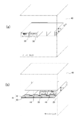
- the power supply unit 20 and the battery unit 30 are shown in FIG. 2A when the server rack 40 is viewed from the front (front) side, and in FIG. Are stored side by side in the server rack 40 as shown in FIG.
- the power supply unit 20 and the battery unit 30 are detachably attached to the server rack 40 from the front side of the server rack 40, respectively.
- connection structure 41 for connecting the power supply unit 20 and the battery unit 30 in parallel is provided on the back side of the server rack 40 as shown in FIG.
- This connection structure 41 is basically connected to the system power supply and supplied with an AC power supply line 42 that supplies an AC voltage (AC200V / AC400V), and a DC voltage that supplies a DC voltage (DC12V) to the server (load device). And a power line 43.
- the connection structure 41 is coupled to the power supply unit 20 and the battery unit 30 via connectors described later.
- the connector 44 provided on the back side of each housing of the power supply unit 20 and the battery unit 30 is composed of one of a plug-in pair and a plug seat.
- the connection structure 41 is provided with the other of the plug and the plug seat.
- the plug-in pair of connectors 44 are connected to the server rack 40 when the power supply unit 20 or the battery unit 30 is mounted, and the server rack of the power supply unit 20 or the battery unit 30 is connected. The connection is released along with the removal from 40.
- the connector 44 serves to connect the power supply circuit unit 21 and the battery circuit unit 31 to the AC power supply line 42 and the DC power line 43, respectively, thereby connecting the power supply unit 20 and the battery unit 30 in parallel. Take on.
- the battery circuit unit 31 is configured to charge the battery 32 by inputting the DC voltage (DC 12V) output from the power circuit unit 21 as described above, the battery circuit unit 31 is provided in the battery unit 30.
- the connector 44 connected connects the battery circuit unit 31 only to the DC power line 43.
- FIGS. 3 (a) and 3 (b) show an example in which single-phase AC power (AC200V) is input.
- the power supply unit 20 has three-phase AC power. It is provided individually for each phase (R, S, T) of the AC power supply.
- the battery unit 30 is provided for each power supply unit 20. In this case, for example, as shown in FIGS. 3 (a) and 3 (b), two rows of storage stages adjacent to each other in the vertical direction of the server rack 40 are used, and the phases for the respective phases (R, S, T).
- the power supply unit 20 and the battery unit 30 are housed side by side.
- connection structure 41 As shown in FIGS. 3A and 3B, the AC power supply line 42 and the DC power line straddle the plurality of storage stages arranged in the vertical direction of the server rack 40. 43 is extended. It is sufficient that the AC power supply line 42 and the DC power line 43 extending in the vertical direction are provided along a support column provided on the back side of the server rack 40. Further, although not shown here, it goes without saying that the connection structure 41 is also provided to extend to other storage stages for storing the server (load equipment) 4 of the server rack 40. Then, a DC voltage (DC 12 V) is supplied to the server (load device) 4 through the DC power line 43 of the connection structure 41.
- DC 12 V DC voltage
- the expansion form of the uninterruptible power supply 10 will be briefly described.
- the power supply unit 20 and the battery unit 30 are each realized in a 1U4 size as described above, so basically two power supply units 20 and two battery units are provided. 30 and stored in a row in the storage stage of the server rack 40 side by side as shown in FIG. Further, when increasing the battery capacity, for example, as shown in FIG. 4B, the battery unit 30 may be added and stored in a storage stage adjacent to the power supply unit 20. Furthermore, when the power capacity itself for the server (load device) 4 is increased, for example, the battery unit 30 may be added together with the power unit 20 as shown in FIG.
- the battery unit 30 may be added to increase the battery capacity.
- FIG. 5B it is of course possible to increase the power supply capacity itself for the server (load device) 4 by adding the power supply unit 20 and the battery unit 30 respectively. In this case, it is desirable to store the power supply unit 20 and the battery unit 30 side by side in each of the three vertical storage stages.
- the power supply unit 20 and the battery unit 30 in the uninterruptible power supply 10 are the same size and are individually configured. Accordingly, the power supply unit 20 and the battery unit 30 can be appropriately added according to the power capacity required for the uninterruptible power supply 10 and according to the backup time of the battery unit 30 at the time of a power failure of the AC power supply. . Therefore, this uninterruptible power supply 10 is rich in expandability, and can construct the power supply system 100 according to various specifications.
- FIG. 6 shows a schematic configuration example of the connection structure 41, in which 44 denotes a connector connected to the AC power supply line 42 and the DC power line 43. These connectors 44 are provided for each storage area of the power supply unit 20 and / or the battery unit 30 obtained by dividing one storage area in the server rack 40 into four in the width direction.
- connection structure 41 is provided with a plurality of terminal portions 45 that separate the DC power line 43 between the adjacent storage areas.
- These terminal portions 45 play a role of sequentially connecting the DC power lines 43 in series via the terminal units when a terminal unit (not shown) is mounted. Therefore, when the terminal unit is removed, the DC power line 43 is disconnected at the mounting position of the terminal portion 45. By disconnecting the DC power line 43 at the terminal portion 45, the DC power line 43 is set so as not to form a loop on the back side of the server rack 40. Further, the DC power lines 43 from the plurality of uninterruptible power supply devices 10 to the plurality of servers (load devices) 4 are set to be the shortest paths.
- the DC power line 43 is also possible to divide the DC power line 43 into a plurality of systems using the terminal unit 45 and to connect the plurality of DC power lines 43 in a hierarchical manner via the terminal unit 45.
- the DC 24V DC power line 43 can be formed from the DC 12V DC power line 43. Therefore, even when the DC 24V system server (load device) 4 is mounted on the server rack 40, the uninterruptible power supply 10 that outputs the DC voltage of 12V described above can cope with it.
- the connector 44 may be any connector having a power supply system terminal structure as shown in FIG. Specifically, three AC terminals 44 a, 44 b, 44 c connected to the AC power supply line 42, a GND terminal 44 d connected to a ground line that defines a reference potential, and positive / negative connected to the DC power line 43. What is necessary is just a power connector provided with a pair of DC terminal 44e, 44f.
- the three AC terminals 44a, 44b, 44c and the power supply circuit section are selected according to which phase of the S phase, T phase, and R phase in the three-phase alternating current is used.
- the connection with 21 can be switched.
- the power supply unit 20 for inputting single-phase alternating current is configured to connect the power supply circuit unit 21 to two predetermined AC terminals among the three AC terminals 44a, 44b, and 44c. It ’s fine.
- the battery unit 30 it is sufficient for the battery unit 30 to be configured to connect to the AC terminals 44a, 44b, and 44c depending on whether or not the battery circuit unit 31 includes the AC / DC converter 34. .
- the power supply circuit unit 21 and the battery circuit unit 31 in the power supply unit 20 and the battery unit 30 are connected to the pair of positive and negative DC terminals 44e and 44f, respectively.
- a connector (not shown) for serial communication as the connector 44, for example.
- a higher-level management unit that manages the operation of the uninterruptible power supply 10 between the power supply unit 20 and the battery unit 30 constituting the uninterruptible power supply 10 via the connector for serial communication. 50 (see FIG. 1) can be configured to communicate with each other.
- the uninterruptible power supply 10 is configured by mounting the power supply unit 20 and the battery unit 30 on the server rack 40, respectively. According to the uninterruptible power supply 10, the power supply performance (capacity) is increased by appropriately adding the power supply unit 20 and the battery unit 30 according to the power capacity required for the uninterruptible power supply 10. Can be easily expanded.
- the wiring length (laying length) of the DC power line 43 from the uninterruptible power supply 10 to the server 4 is short, the wiring inductance can be reduced. Therefore, even when the load power in the server 4 changes abruptly, the operation of the uninterruptible power supply 10 can be made to respond at high speed by following the change. As a result, it is possible to minimize fluctuations in the DC voltage (DC 12 V) supplied to the server 4 and stabilize the DC voltage (DC 12 V).
- the power unit 20 having a higher operating rate than the battery unit 30 is generally disposed at a position where the line length of the DC power line 43 is shorter than the server 4, the DC voltage (DC12V) Power supply with low loss can be realized.
- the position where the DC power line 43 is disconnected by the terminal unit 45 may be set so that the line length of the DC power line 43 to the server 4 is the shortest.
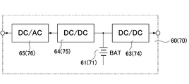
- the auxiliary battery unit 60 includes, for example, a battery 61 made of a Li ion battery or the like as shown in FIG. 8, and DC / DC for charging the battery 61 by converting the direct current power obtained by the solar power generation device.
- a converter 62 is provided.
- the auxiliary battery unit 60 includes a DC / DC converter 63 that converts the DC power stored in the battery 61 into the DC voltage (DC12V) and outputs the same.
- the auxiliary battery unit 60 is also housed in a casing having the same dimensions as the power supply unit 20.
- the auxiliary battery unit 70 includes, for example, a battery 71 made of a Li ion battery, an AC / DC converter 72 that converts AC power obtained by the wind power generator, as shown in FIG. A DC / DC converter 73 that charges the battery 71 by converting the output voltage of the DC converter 72 is provided. Further, the auxiliary battery unit 70 includes a DC / DC converter 74 that converts the DC power stored in the battery 71 into the DC voltage (DC12V) and outputs the same. The auxiliary battery unit 70 is also housed in a housing having the same dimensions as the power supply unit 20.
- assistant battery unit 60,70 and the said wind power generation device it is clearly different from the alternating current power supply line 42 mentioned above, for example of each said auxiliary
- each of the auxiliary battery units 60 and 70 has a DC / DC converter 64 (75) for converting DC power stored in the battery 61 (71) by voltage conversion, and this DC.
- a DC / AC converter 65 (76) for generating the AC power (AC 200V) from the output of the / DC converter 64 (75) is provided. It is also useful to configure so that the output (AC 200 V) of the DC / AC converter 65 (76) can be fed to the AC power supply line 42.
- the battery unit 30 is connected with the DC power stored in the batteries 61 and 71 of the auxiliary battery units 60 and 70, respectively.
- the power supply performance of the power supply unit 20 can be effectively backed up.
- a part of direct current power (DC 12 V) fed from the power supply unit 20 to the server 4 can be supplemented with power that can be output from the auxiliary battery units 60 and 70. Therefore, the load applied to the power supply unit 20 can be reduced.
- control units 26 and 36 mounted on the power supply unit 20 and the battery unit 30 and their control functions will be described. These control units 26 and 36 basically serve to control operations of the power supply circuit unit 21 and the battery circuit unit 31.
- the control units 26 and 36 control the fan drive units 27 and 37, respectively, to control the rotation speeds (air volumes) of the fan devices 28 and 38 provided in the housings of the power supply unit 20 and the battery unit 30, respectively. It also has a function to control.
- the fan devices 28 and 38 allow air to flow inside the respective casings and release heat generated by the power supply circuit unit 21 and the battery circuit unit 31 to the outside of the casings.
- the fan devices 28 and 38 serve to prevent overheating (high temperature) of the power supply circuit unit 21 and the battery circuit unit 31 due to the heat release.
- the fan devices 28 and 38 are generally provided at the back of the casing, and release the heat inside the casing by blowing air toward the back side of the server rack 40.
- the unbalance compensation control function 51 uses the R-phase, S-phase, and T-phase power amounts from the R phase, S phase, and T phase in the above-described three-phase AC input uninterruptible power supply 10. Monitor for imbalances.
- the unbalance compensation control function 51 uses the charge / discharge power of each battery 32 in the battery unit 30 of each phase to control the amount of power output from the power supply unit 20 of each phase, thereby Compensates for unbalance between the phases.
- the backup control function 52 generally indicates that the operating state (output current) of the power supply unit 20 is equal to or lower than the rated power of the power supply unit 20, and the storage state (charge capacity) in the battery unit 30 is fully charged. It is activated when less than In this case, the backup control function 52 determines, for example, the difference between the rated current of the power supply unit 20 and the output current amount of the power supply unit 20 as the surplus current amount that the power supply unit 20 can further output, that is, the surplus power amount. Asking. The backup control function 52 charges the battery 32 of the battery unit 30 using the surplus power and stores DC power in the battery 32. The battery 32 is charged until the battery 32 is fully charged. This charge control is particularly effective when power energy from the above-described solar power generation device or wind power generation device cannot be obtained.
- the conversion efficiency control function 53 plays a role of increasing the conversion efficiency in the power supply unit 20 by controlling the charge / discharge of the battery 32.
- This conversion efficiency control is executed, for example, by obtaining a ratio (load ratio; X% load) to the maximum load from the amount of output current of the power supply unit 20.
- the difference of the load ratio for example, 30% load
- the charging / discharging of the battery unit 30 is controlled by the difference so that the load ratio of the power supply unit 20 is 30%, thereby adjusting the amount of current output from the power supply unit 20.
- a load current amount required for the power supply unit 20 corresponds to a 50% load
- a current corresponding to a 20% load that is a difference from the 30% load is supplied from the battery unit 30.
- the power supply unit 20 outputs only a 30% load current, so that the operation of the power supply unit 20 is brought into a 30% load state.
- the load current amount required for the power supply unit 20 corresponds to a 25% load
- an extra current corresponding to a 5% load which is a difference from the 30% load, is taken out from the power supply unit 20.
- the current of the 5% load is used for charging the battery unit 30 to set the operation of the power supply unit 20 to the 30% load state.
- the operation of the power supply unit 20 is set to a 30% load state, and the conversion efficiency ⁇ is increased to increase the efficiency of the entire uninterruptible power supply 10.
- the overload control function 54 performs the overload operation of the power supply unit 20 when the load of the server 4 temporarily becomes heavy and the load current output from the power supply unit 20 exceeds the rated current. Play a role to suppress.
- the overload control function 54 is executed when the amount of load current supplied to the server 4 side exceeds the rated current of the power supply unit 20. Then, the overload control function 54 obtains the difference between the load current and the rated current as an amount of current that is insufficient for the server 4, and the current corresponding to the amount of insufficient current is obtained from the battery unit 30. The operation of the battery unit 30 is controlled.
- the server 4 is supplied with both the current output from the power supply unit 20 and the current output from the battery unit 30.
- the current (load current amount) output from the power supply unit 20 can be suppressed to the rated current.
- the amount of load current required for the power supply unit 20 that exceeds the rated current is supplemented by the current from the battery unit 30.
- the power failure control function 55 is a case where a plurality of uninterruptible power supply devices 10 are controlled in parallel under the management of the management unit 15, and the high-voltage AC power (AC 400V) from the system power source. Executed when the supply of is cut off. Specifically, at the time of a power failure, each of the uninterruptible power supply devices 10 basically switches the power supply to the server 4 that each of the uninterruptible power supply devices 10 is supplied to from the battery unit 30. At this time, the power failure control function 55 determines the amount of power stored in each battery unit 30 of the plurality of uninterruptible power supply devices 10 and the amount of current to be supplied to the server 4 from each battery unit 30. The backup possible time during which power can be supplied to the server 4 is obtained.
- auxiliary battery units 60 and 70 are provided and AC power (AC200V / AC400V) is output from the auxiliary battery units 60 and 70 to the AC power supply line 42, the following is performed.
- the power supply unit 20 can be prevented from shifting to the complete power failure mode.
- the auxiliary battery unit can be secured to a certain extent from the AC power supply line 42 for the operation of the uninterruptible power supply 10.
- DC power stored in 60 and 70 is converted into AC voltage and output to the AC power (AC200V / AC400V) feed line.
- the fan control function 56 plays a role of driving the fan devices 28 and 38 even when the power supply unit 20 and / or the battery unit 30 has stopped its operation.
- the fan devices 28 and 38 form an air flow inside the housing containing the power supply unit 20 and the battery unit 30 and discharge heat generated inside the housing to the outside.
- the fan devices 28 and 38 serve to cool the entire uninterruptible power supply 10 by discharging the heat in the server rack 40 to the outside.
- the fan control function 56 prevents the stagnation of the air flow in the server rack 40 by driving the fan devices 28 and 38 having such a role, thereby causing local overheating in the server rack 40. Is preventing.
- the fan control function 56 collects not only the load status of each uninterruptible power supply 10 but also the load status of the server 4.
- the rotational speeds of the fan devices 28 and 38 are individually controlled according to these load conditions, thereby forming a smooth air flow in the server rack 40.
- the collection of the load status is performed by information communication between the power supply unit 20 and the battery unit 30 constituting the uninterruptible power supply 10, further the auxiliary battery units 60 and 70, and the server 4. Is called.
- the storage location in the server rack 40 is determined by, for example, the mounting position identification provided in each of the units 20, 30, 60, and 70. It may be preset in advance using the DIP switch.
- the power supply unit 20 when the power supply unit 20 shifts to the complete power failure mode due to the power failure of the AC power (AC200V / AC400V), power can be supplied from the battery unit 30 to the server 4. it can.
- the operation (operation) of the server 4 can be continued even during the power failure. Therefore, for example, if the power supply unit 20 is removed from the server rack 40, the operation of the power supply unit 20 can be forcibly stopped. That is, the power supply unit 20 can be set to the complete stop mode in a pseudo manner.
- DC power (DC 12 V) is supplied from the battery unit 30 connected in parallel to the power supply unit 20 to the server 4. Therefore, if the discharge characteristic of the battery 32 in the battery unit 30 at this time, specifically, the change in the charging voltage of the battery 32 with the passage of time is measured, the degree of characteristic deterioration of the battery 32 from the measured discharge characteristic. Can be easily diagnosed.
- the output of the power supply unit 20 is forcibly set to zero [0] or reduced.
- the discharge characteristic of the said battery 32 in the said battery unit 30 at that time specifically, the change of the charging voltage of the said battery 32 with time passage are measured.
- the degree of characteristic deterioration of the battery 32 can be diagnosed from the measured discharge characteristics of the battery 32. In this way, deterioration diagnosis of the battery 32 can be performed without forcibly generating a power failure state by artificially disconnecting the input or output of the power supply unit 20 from the server rack 40 or removing the power supply unit 20. Can be performed.
- the battery remains in a state where the power supply system 100 is operated without causing a pseudo power failure of the AC power (AC200V / AC400V).
- the deterioration diagnosis of the battery 32 provided in the unit 30 can be easily executed.
- the deterioration diagnosis of the battery 32 can be individually performed for each battery unit 30 in the plurality of uninterruptible power supply apparatuses 10. Therefore, in operating this power supply system 100, the AC power (AC200V / AC400V) does not need to be artificially interrupted, so that the maintenance can be carried out easily, efficiently and safely. The effect of becoming.
- the uninterruptible power supply 10 it is possible to achieve stable operation including the above-mentioned incidental control functions. Furthermore, as described above, the power supply system 100 with high expandability can be easily configured, and there are significant effects in practical use such as low cost. Furthermore, since the power supply unit 20 and the battery unit 30 can be housed and configured in a small casing that can be mounted on the server rack 40, the handling is easy. Since it can be easily attached and detached, the effects such as easy maintenance can be achieved.
Landscapes
- Engineering & Computer Science (AREA)
- Power Engineering (AREA)
- Business, Economics & Management (AREA)
- Emergency Management (AREA)
- Stand-By Power Supply Arrangements (AREA)
- Charge And Discharge Circuits For Batteries Or The Like (AREA)
- Power Sources (AREA)
Abstract
La présente invention comprend : une unité de source d'alimentation (20) qui contient, dans un boîtier ayant des dimensions préconisées, une partie circuit de source d'alimentation (21) destinée à convertir le courant alternatif et à générer une tension continue qui doit être fournie à un dispositif de charge (4) ; une unité de batterie (30) agencée en alignement avec l'unité de source d'alimentation, l'unité de batterie (30) contenant, dans un boîtier ayant les mêmes dimensions que celles de l'unité de source d'alimentation, une partie circuit de batterie (31) destinée à stocker le courant continu et à décharger le courant continu stocké afin de générer une tension continue qui doit être fournie au dispositif de charge ; et un bâti (40) sur lequel sont montées de manière amovible l'unité de source d'alimentation et l'unité de batterie, le bâti (40) raccordant en parallèle la partie circuit de source d'alimentation de l'unité de source d'alimentation et la partie circuit de batterie de l'unité de batterie.
Priority Applications (3)
| Application Number | Priority Date | Filing Date | Title |
|---|---|---|---|
| PCT/JP2013/057560 WO2014141486A1 (fr) | 2013-03-15 | 2013-03-15 | Appareil de source d'alimentation sans coupure |
| JP2015505213A JP6048572B2 (ja) | 2013-03-15 | 2013-03-15 | 無停電電源装置 |
| US14/642,649 US9899835B2 (en) | 2013-03-15 | 2015-03-09 | Uninterruptible power supply system |
Applications Claiming Priority (1)
| Application Number | Priority Date | Filing Date | Title |
|---|---|---|---|
| PCT/JP2013/057560 WO2014141486A1 (fr) | 2013-03-15 | 2013-03-15 | Appareil de source d'alimentation sans coupure |
Related Child Applications (1)
| Application Number | Title | Priority Date | Filing Date |
|---|---|---|---|
| US14/642,649 Continuation US9899835B2 (en) | 2013-03-15 | 2015-03-09 | Uninterruptible power supply system |
Publications (1)
| Publication Number | Publication Date |
|---|---|
| WO2014141486A1 true WO2014141486A1 (fr) | 2014-09-18 |
Family
ID=51536179
Family Applications (1)
| Application Number | Title | Priority Date | Filing Date |
|---|---|---|---|
| PCT/JP2013/057560 Ceased WO2014141486A1 (fr) | 2013-03-15 | 2013-03-15 | Appareil de source d'alimentation sans coupure |
Country Status (3)
| Country | Link |
|---|---|
| US (1) | US9899835B2 (fr) |
| JP (1) | JP6048572B2 (fr) |
| WO (1) | WO2014141486A1 (fr) |
Cited By (2)
| Publication number | Priority date | Publication date | Assignee | Title |
|---|---|---|---|---|
| JP2017127045A (ja) * | 2016-01-12 | 2017-07-20 | 富士電機株式会社 | 電源システム |
| JP2017162274A (ja) * | 2016-03-10 | 2017-09-14 | 日本電気株式会社 | 情報処理システム |
Families Citing this family (30)
| Publication number | Priority date | Publication date | Assignee | Title |
|---|---|---|---|---|
| GB2510899A (en) * | 2013-02-19 | 2014-08-20 | Eltek As | Power supply system module |
| CN103701189B (zh) * | 2013-12-25 | 2016-01-13 | 联方云天科技(北京)有限公司 | 一种网络化的分布式动态均衡供电方法 |
| CN103683270B (zh) * | 2013-12-26 | 2016-01-20 | 联方云天科技(北京)有限公司 | 一种网络化的分布式高压直流供电管理方法 |
| KR101582850B1 (ko) * | 2013-12-30 | 2016-01-07 | 주식회사 효성 | Hvdc 시스템의 전원 이중화 장치 및 그 제어방법 |
| WO2015157999A1 (fr) * | 2014-04-18 | 2015-10-22 | Schneider Electric It Corporation | Système et procédés permettant des alimentations sans coupure distribuées |
| US10637264B2 (en) * | 2014-09-24 | 2020-04-28 | Powertec Solutions International Llc | Portable switching power supply with attachable battery pack and enclosure |
| EP3232532A4 (fr) * | 2014-12-08 | 2018-08-15 | Toshiba Mitsubishi-Electric Industrial Systems Corporation | Dispositif d'alimentation sans coupure |
| CN104682375A (zh) * | 2015-03-24 | 2015-06-03 | 华为技术有限公司 | 数据中心的供电设备和供电方法 |
| CN106611995B (zh) * | 2015-10-23 | 2019-04-16 | 光宝电子(广州)有限公司 | 具有主动电压调整的不断电电源供电方法及设备 |
| WO2017127088A1 (fr) * | 2016-01-21 | 2017-07-27 | Hewlett Packard Enterprise Development Lp | Dispositif à alimentations principale et de secours |
| TWI586076B (zh) * | 2016-05-24 | 2017-06-01 | 群光電能科技股份有限公司 | 電池充電裝置及充電系統 |
| JP6588412B2 (ja) * | 2016-09-30 | 2019-10-09 | Necプラットフォームズ株式会社 | 電力制御装置、電力制御方法、及び電力制御システム |
| US11309714B2 (en) * | 2016-11-02 | 2022-04-19 | Tesla, Inc. | Micro-batteries for energy generation systems |
| US10069407B1 (en) * | 2017-03-02 | 2018-09-04 | Hewlett Packard Enterprise Development Lp | Converters to convert input voltages to output voltages |
| US10923947B2 (en) * | 2017-04-03 | 2021-02-16 | Smart Charging Technologies Llc | Direct current uninterruptible power supply with cloud server and related methods |
| US10998746B2 (en) | 2017-04-03 | 2021-05-04 | Smart Charging Technologies Llc | Direct current uninterruptible power supply with AC power supply and related methods |
| US10873206B2 (en) | 2017-05-30 | 2020-12-22 | Schneider Electric It Corporation | System and method for power storage and distribution |
| EP3422531A1 (fr) * | 2017-06-26 | 2019-01-02 | Siemens Aktiengesellschaft | Procédé de commande d'un système d'alimentation électrique en continu et système d'alimentation électrique associé |
| CN111384763A (zh) * | 2018-12-28 | 2020-07-07 | 远景能源(江苏)有限公司 | 一种电能变换与控制装置以及具有该装置的储能系统 |
| US10847994B2 (en) | 2019-03-15 | 2020-11-24 | Seagate Technology Llc | Data center power distribution system |
| DE202019103388U1 (de) * | 2019-06-17 | 2019-06-27 | Wacker Neuson Produktion GmbH & Co. KG | Stromversorgungseinheit mit einem Gehäuse und einem aufladbaren, elektrischen Speicher |
| US11735948B2 (en) * | 2019-07-26 | 2023-08-22 | Baidu Usa Llc | Bi-directional multi-function converter for backup battery unit |
| US11237610B2 (en) * | 2019-11-20 | 2022-02-01 | Intel Corporation | Handling loss of power for uninterruptible power supply efficiency |
| TWI705642B (zh) * | 2020-01-15 | 2020-09-21 | 旭隼科技股份有限公司 | 不斷電系統裝置及方法 |
| CN113141738B (zh) * | 2020-01-20 | 2022-07-22 | 日月元科技(深圳)有限公司 | 不断电系统装置及方法 |
| CN112196739B (zh) * | 2020-10-10 | 2022-04-26 | 国电联合动力技术有限公司 | 一种风力发电机组不间断电源智能调控系统和方法 |
| KR102654899B1 (ko) | 2020-11-13 | 2024-04-03 | 주식회사 엘지에너지솔루션 | 배터리 활성화를 위한 직류 배전 기반의 충방전 시스템 |
| WO2023117068A1 (fr) * | 2021-12-22 | 2023-06-29 | Huawei Digital Power Technologies Co., Ltd. | Système d'alimentation électrique pour centre de données |
| CN114977168A (zh) * | 2022-06-17 | 2022-08-30 | 上海安世博能源科技有限公司 | 供电系统及供电方法 |
| US12562573B2 (en) * | 2023-10-24 | 2026-02-24 | Microsoft Technology Licensing, Llc | Power stabilization using energy storage |
Citations (3)
| Publication number | Priority date | Publication date | Assignee | Title |
|---|---|---|---|---|
| JP2003309935A (ja) * | 2002-04-16 | 2003-10-31 | Hitachi Ltd | 直流バックアップ電源装置 |
| JP2005124268A (ja) * | 2003-10-14 | 2005-05-12 | Densei Lambda Kk | 電源装置およびバックアップ電源システム |
| JP2011125124A (ja) * | 2009-12-09 | 2011-06-23 | Sanyo Electric Co Ltd | サーバーとサーバーに収納される無停電電源装置 |
Family Cites Families (13)
| Publication number | Priority date | Publication date | Assignee | Title |
|---|---|---|---|---|
| JP3250354B2 (ja) | 1993-12-24 | 2002-01-28 | オムロン株式会社 | 電源装置 |
| JP2003264939A (ja) * | 2002-03-08 | 2003-09-19 | Hitachi Ltd | 電源装置およびそれを用いた情報処理システム |
| JP2005176461A (ja) * | 2003-12-09 | 2005-06-30 | Matsushita Electric Ind Co Ltd | 直流無停電電源装置 |
| JP4673019B2 (ja) * | 2004-09-10 | 2011-04-20 | 日立コンピュータ機器株式会社 | 情報処理装置 |
| JP2006230029A (ja) | 2005-02-15 | 2006-08-31 | Hitachi Ltd | 無停電電源装置 |
| US20080012423A1 (en) * | 2006-07-13 | 2008-01-17 | Emile Mimran | USB connector devices for charging |
| JP5583394B2 (ja) * | 2009-12-09 | 2014-09-03 | Fdk株式会社 | サーバーの無停電電源装置 |
| JP5562054B2 (ja) * | 2010-01-29 | 2014-07-30 | 富士通株式会社 | テーブルタップ及び電力測定システム |
| CN102859467B (zh) * | 2010-04-30 | 2015-11-25 | 富士通株式会社 | 不间断电源装置和其使用方法及服务器系统 |
| KR101193168B1 (ko) * | 2010-08-20 | 2012-10-19 | 삼성에스디아이 주식회사 | 전력 저장 시스템, 그 제어방법 및 이를 실행시키기 위한 프로그램을 저장한 기록매체 |
| JP5687498B2 (ja) | 2011-01-05 | 2015-03-18 | 株式会社Nttファシリティーズ | 電力変換システム |
| JP5662877B2 (ja) * | 2011-06-03 | 2015-02-04 | ルネサスエレクトロニクス株式会社 | 蓄電池システム |
| US9478981B2 (en) * | 2012-09-26 | 2016-10-25 | Samsung Sdi Co., Ltd. | Battery system having identifiers and energy storage system including the same |
-
2013
- 2013-03-15 WO PCT/JP2013/057560 patent/WO2014141486A1/fr not_active Ceased
- 2013-03-15 JP JP2015505213A patent/JP6048572B2/ja active Active
-
2015
- 2015-03-09 US US14/642,649 patent/US9899835B2/en active Active
Patent Citations (3)
| Publication number | Priority date | Publication date | Assignee | Title |
|---|---|---|---|---|
| JP2003309935A (ja) * | 2002-04-16 | 2003-10-31 | Hitachi Ltd | 直流バックアップ電源装置 |
| JP2005124268A (ja) * | 2003-10-14 | 2005-05-12 | Densei Lambda Kk | 電源装置およびバックアップ電源システム |
| JP2011125124A (ja) * | 2009-12-09 | 2011-06-23 | Sanyo Electric Co Ltd | サーバーとサーバーに収納される無停電電源装置 |
Cited By (2)
| Publication number | Priority date | Publication date | Assignee | Title |
|---|---|---|---|---|
| JP2017127045A (ja) * | 2016-01-12 | 2017-07-20 | 富士電機株式会社 | 電源システム |
| JP2017162274A (ja) * | 2016-03-10 | 2017-09-14 | 日本電気株式会社 | 情報処理システム |
Also Published As
| Publication number | Publication date |
|---|---|
| US20150180232A1 (en) | 2015-06-25 |
| US9899835B2 (en) | 2018-02-20 |
| JP6048572B2 (ja) | 2016-12-21 |
| JPWO2014141486A1 (ja) | 2017-02-16 |
Similar Documents
| Publication | Publication Date | Title |
|---|---|---|
| JP6048572B2 (ja) | 無停電電源装置 | |
| CN104620469B (zh) | 不间断电源装置 | |
| JP6070819B2 (ja) | 電源システム | |
| US11588337B2 (en) | Centralized charging cabinet provided with isolation area and charging area | |
| US9153374B2 (en) | Cooling arrangements for drive systems | |
| US8976526B2 (en) | Providing a cooling system for a medium voltage drive system | |
| US8254076B2 (en) | Providing modular power conversion | |
| CA2924654C (fr) | Modules electroniques refroidis par liquide et leurs procedes de remplacement | |
| US12255482B2 (en) | Plug-in type energy storage system | |
| EP3625870B1 (fr) | Virtualisation d'énergie pour centres de données, environnements de télécommunications et infrastructures équivalentes | |
| EP3692618B1 (fr) | Unité de puissance au sol entraînée par batterie présentant une construction, une durabilité et une maintenance améliorées | |
| CN111835055B (zh) | 集中式充电柜 | |
| KR102768513B1 (ko) | 전력 변환기에 사용하기 위한 냉각 시스템 | |
| WO2011008514A2 (fr) | Cellule de puissance enfichable destinée à un onduleur et assurant une conversion de puissance modulaire | |
| CN105529746B (zh) | 一种柔性配电系统 | |
| CN113809766B (zh) | 一种多母线储能系统及其控制方法 | |
| CN223450963U (zh) | 一种移动式储能装置 | |
| KR101576249B1 (ko) | 디지털 제어를 통한 배터리의 고효율 다중 충전기 시스템 | |
| CN121886534A (zh) | 储能系统 | |
| CN121417410A (zh) | 一种稳压hvdc电池系统及电源柜 | |
| WO2022233647A1 (fr) | Système d'alimentation électrique mobile comprenant un onduleur multiniveau en cascade |
Legal Events
| Date | Code | Title | Description |
|---|---|---|---|
| 121 | Ep: the epo has been informed by wipo that ep was designated in this application |
Ref document number: 13878000 Country of ref document: EP Kind code of ref document: A1 |
|
| ENP | Entry into the national phase |
Ref document number: 2015505213 Country of ref document: JP Kind code of ref document: A |
|
| NENP | Non-entry into the national phase |
Ref country code: DE |
|
| 122 | Ep: pct application non-entry in european phase |
Ref document number: 13878000 Country of ref document: EP Kind code of ref document: A1 |