WO2014141525A1 - Bloc de batteries - Google Patents
Bloc de batteries Download PDFInfo
- Publication number
- WO2014141525A1 WO2014141525A1 PCT/JP2013/079110 JP2013079110W WO2014141525A1 WO 2014141525 A1 WO2014141525 A1 WO 2014141525A1 JP 2013079110 W JP2013079110 W JP 2013079110W WO 2014141525 A1 WO2014141525 A1 WO 2014141525A1
- Authority
- WO
- WIPO (PCT)
- Prior art keywords
- film
- fixing member
- clad
- battery
- assembled battery
- Prior art date
- Legal status (The legal status is an assumption and is not a legal conclusion. Google has not performed a legal analysis and makes no representation as to the accuracy of the status listed.)
- Ceased
Links
Images


Classifications
-
- H—ELECTRICITY
- H01—ELECTRIC ELEMENTS
- H01M—PROCESSES OR MEANS, e.g. BATTERIES, FOR THE DIRECT CONVERSION OF CHEMICAL ENERGY INTO ELECTRICAL ENERGY
- H01M10/00—Secondary cells; Manufacture thereof
- H01M10/05—Accumulators with non-aqueous electrolyte
- H01M10/052—Li-accumulators
- H01M10/0525—Rocking-chair batteries, i.e. batteries with lithium insertion or intercalation in both electrodes; Lithium-ion batteries
-
- H—ELECTRICITY
- H01—ELECTRIC ELEMENTS
- H01M—PROCESSES OR MEANS, e.g. BATTERIES, FOR THE DIRECT CONVERSION OF CHEMICAL ENERGY INTO ELECTRICAL ENERGY
- H01M50/00—Constructional details or processes of manufacture of the non-active parts of electrochemical cells other than fuel cells, e.g. hybrid cells
- H01M50/20—Mountings; Secondary casings or frames; Racks, modules or packs; Suspension devices; Shock absorbers; Transport or carrying devices; Holders
- H01M50/204—Racks, modules or packs for multiple batteries or multiple cells
- H01M50/207—Racks, modules or packs for multiple batteries or multiple cells characterised by their shape
- H01M50/211—Racks, modules or packs for multiple batteries or multiple cells characterised by their shape adapted for pouch cells
-
- H—ELECTRICITY
- H01—ELECTRIC ELEMENTS
- H01M—PROCESSES OR MEANS, e.g. BATTERIES, FOR THE DIRECT CONVERSION OF CHEMICAL ENERGY INTO ELECTRICAL ENERGY
- H01M50/00—Constructional details or processes of manufacture of the non-active parts of electrochemical cells other than fuel cells, e.g. hybrid cells
- H01M50/20—Mountings; Secondary casings or frames; Racks, modules or packs; Suspension devices; Shock absorbers; Transport or carrying devices; Holders
- H01M50/218—Mountings; Secondary casings or frames; Racks, modules or packs; Suspension devices; Shock absorbers; Transport or carrying devices; Holders characterised by the material
- H01M50/22—Mountings; Secondary casings or frames; Racks, modules or packs; Suspension devices; Shock absorbers; Transport or carrying devices; Holders characterised by the material of the casings or racks
- H01M50/227—Organic material
-
- H—ELECTRICITY
- H01—ELECTRIC ELEMENTS
- H01M—PROCESSES OR MEANS, e.g. BATTERIES, FOR THE DIRECT CONVERSION OF CHEMICAL ENERGY INTO ELECTRICAL ENERGY
- H01M50/00—Constructional details or processes of manufacture of the non-active parts of electrochemical cells other than fuel cells, e.g. hybrid cells
- H01M50/20—Mountings; Secondary casings or frames; Racks, modules or packs; Suspension devices; Shock absorbers; Transport or carrying devices; Holders
- H01M50/233—Mountings; Secondary casings or frames; Racks, modules or packs; Suspension devices; Shock absorbers; Transport or carrying devices; Holders characterised by physical properties of casings or racks, e.g. dimensions
- H01M50/24—Mountings; Secondary casings or frames; Racks, modules or packs; Suspension devices; Shock absorbers; Transport or carrying devices; Holders characterised by physical properties of casings or racks, e.g. dimensions adapted for protecting batteries from their environment, e.g. from corrosion
-
- H—ELECTRICITY
- H01—ELECTRIC ELEMENTS
- H01M—PROCESSES OR MEANS, e.g. BATTERIES, FOR THE DIRECT CONVERSION OF CHEMICAL ENERGY INTO ELECTRICAL ENERGY
- H01M50/00—Constructional details or processes of manufacture of the non-active parts of electrochemical cells other than fuel cells, e.g. hybrid cells
- H01M50/20—Mountings; Secondary casings or frames; Racks, modules or packs; Suspension devices; Shock absorbers; Transport or carrying devices; Holders
- H01M50/262—Mountings; Secondary casings or frames; Racks, modules or packs; Suspension devices; Shock absorbers; Transport or carrying devices; Holders with fastening means, e.g. locks
- H01M50/264—Mountings; Secondary casings or frames; Racks, modules or packs; Suspension devices; Shock absorbers; Transport or carrying devices; Holders with fastening means, e.g. locks for cells or batteries, e.g. straps, tie rods or peripheral frames
-
- H—ELECTRICITY
- H01—ELECTRIC ELEMENTS
- H01M—PROCESSES OR MEANS, e.g. BATTERIES, FOR THE DIRECT CONVERSION OF CHEMICAL ENERGY INTO ELECTRICAL ENERGY
- H01M50/00—Constructional details or processes of manufacture of the non-active parts of electrochemical cells other than fuel cells, e.g. hybrid cells
- H01M50/50—Current conducting connections for cells or batteries
- H01M50/543—Terminals
- H01M50/547—Terminals characterised by the disposition of the terminals on the cells
- H01M50/55—Terminals characterised by the disposition of the terminals on the cells on the same side of the cell
-
- H—ELECTRICITY
- H01—ELECTRIC ELEMENTS
- H01M—PROCESSES OR MEANS, e.g. BATTERIES, FOR THE DIRECT CONVERSION OF CHEMICAL ENERGY INTO ELECTRICAL ENERGY
- H01M50/00—Constructional details or processes of manufacture of the non-active parts of electrochemical cells other than fuel cells, e.g. hybrid cells
- H01M50/50—Current conducting connections for cells or batteries
- H01M50/543—Terminals
- H01M50/552—Terminals characterised by their shape
- H01M50/553—Terminals adapted for prismatic, pouch or rectangular cells
- H01M50/557—Plate-shaped terminals
-
- Y—GENERAL TAGGING OF NEW TECHNOLOGICAL DEVELOPMENTS; GENERAL TAGGING OF CROSS-SECTIONAL TECHNOLOGIES SPANNING OVER SEVERAL SECTIONS OF THE IPC; TECHNICAL SUBJECTS COVERED BY FORMER USPC CROSS-REFERENCE ART COLLECTIONS [XRACs] AND DIGESTS
- Y02—TECHNOLOGIES OR APPLICATIONS FOR MITIGATION OR ADAPTATION AGAINST CLIMATE CHANGE
- Y02E—REDUCTION OF GREENHOUSE GAS [GHG] EMISSIONS, RELATED TO ENERGY GENERATION, TRANSMISSION OR DISTRIBUTION
- Y02E60/00—Enabling technologies; Technologies with a potential or indirect contribution to GHG emissions mitigation
- Y02E60/10—Energy storage using batteries
-
- Y—GENERAL TAGGING OF NEW TECHNOLOGICAL DEVELOPMENTS; GENERAL TAGGING OF CROSS-SECTIONAL TECHNOLOGIES SPANNING OVER SEVERAL SECTIONS OF THE IPC; TECHNICAL SUBJECTS COVERED BY FORMER USPC CROSS-REFERENCE ART COLLECTIONS [XRACs] AND DIGESTS
- Y02—TECHNOLOGIES OR APPLICATIONS FOR MITIGATION OR ADAPTATION AGAINST CLIMATE CHANGE
- Y02T—CLIMATE CHANGE MITIGATION TECHNOLOGIES RELATED TO TRANSPORTATION
- Y02T10/00—Road transport of goods or passengers
- Y02T10/60—Other road transportation technologies with climate change mitigation effect
- Y02T10/70—Energy storage systems for electromobility, e.g. batteries
Definitions
- the present invention relates to an assembled battery in which a plurality of film-clad batteries in which a power generation element is housed in a film-clad material together with an electrolyte are stacked.
- secondary batteries represented by lithium ion batteries are installed not only in portable devices such as mobile phones and digital cameras, but also in electric bicycles, electric bikes, and automobiles. As the use of secondary batteries diversifies, the weight of batteries and the freedom of design are required.
- a film-clad battery using a film-like packaging material that is lightweight and has a high degree of freedom in shape is known.
- an assembled battery in which a plurality of film-clad batteries are stacked is known for applications that require high power.
- Patent Document 1 discloses a technique related to fixing a film-clad battery.
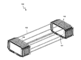
- FIG. 1 is a perspective view of an assembled battery disclosed in Patent Document 1.
- the film-clad batteries are housed one by one in the cell case 101.
- a communication hole 102 is formed in the cell case 101.
- a rod 103 is inserted into the communication hole 102.
- a nut is engaged with the end 104 of the rod 103. In this way, by fixing the plurality of cell cases 101 with the rods 103, the film-clad batteries housed in the cell case 101 are fixed.
- the thickness of the cell case 101 is added to the thickness of the assembled battery 10. Therefore, as the number of cell cases 101 increases, the thickness of the assembled battery 10 increases significantly, leading to an increase in the size of the battery.
- an object of the present invention is to provide an assembled battery capable of suppressing the thickness of the entire battery while securing fixation between film-clad batteries.
- the assembled battery of the present invention includes a power generation element in which positive electrodes and negative electrodes are alternately stacked via separators, and a film exterior in which an internal space capable of accommodating the power generation element together with an electrolyte is formed.
- a film-clad battery assembly in which a plurality of film-clad batteries having a material are stacked, and at least one fixing member facing a side surface of the film-clad battery assembly.
- the film exterior material includes a storage portion that forms the internal space, and a sealing portion that extends from the storage portion to the fixing member and seals the internal space. The said sealing part is being fixed to the said fixing member in the state inserted in the slit formed in the said fixing member.
- the present invention it is possible to suppress the thickness of the entire battery while securing the fixation between the film-clad batteries.
- FIG. 1 is a perspective view of an assembled battery disclosed in Patent Document 1.
- FIG. FIG. 3 is a cross-sectional view illustrating a structure of the assembled battery according to the first embodiment. It is a top view which shows the structure of the film-clad battery shown in FIG. It is an exploded view of the film-clad battery shown in FIG. It is a figure which shows the cross-section of a film material. It is a perspective view of a fixing member.
- FIG. 6 is a cross-sectional view illustrating a structure of an assembled battery according to Embodiment 2.
- FIG. 6 is a cross-sectional view illustrating a structure of an assembled battery according to Embodiment 3.
- 6 is a cross-sectional view showing a structure of an assembled battery according to Embodiment 4.
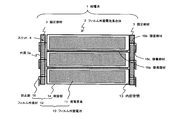
- FIG. 2 is a cross-sectional view illustrating the structure of the assembled battery according to the first embodiment.
- the assembled battery 1 includes a film-clad battery assembly 2 and a fixing member 3.
- the film-clad battery assembly 2 is composed of a plurality of film-clad batteries 10.
- the plurality of film-clad batteries 10 are stacked on each other and bonded by an adhesive member 16a.
- the fixing member 3 faces the film-clad battery assembly 2 in the width direction perpendicular to the stacking direction.
- FIG. 3 is a plan view showing the structure of the film-clad battery 10 shown in FIG.
- FIG. 4 is an exploded view of the film-clad battery shown in FIG. FIG. 4 corresponds to a cross-sectional view along the cutting line AA shown in FIG.
- each film-clad battery 10 includes a power generating element 11 that can be charged and discharged, and a film outer packaging material 12 in which the power generating element 11 is accommodated.
- the power generation element 11 is configured by alternately stacking a plurality of positive electrodes 7 and negative electrodes 9 via separators 8 (see FIG. 4).
- a positive electrode lead terminal 17 (see FIG. 3) is connected to the positive electrode 7.
- a negative electrode lead terminal 18 (see FIG. 3) is connected to the negative electrode 9.
- the positive electrode lead terminal 17 and the negative electrode lead terminal 18 may protrude from the power generation element 11 in the same direction, or may protrude from the power generation element 11 in opposite directions.
- the film exterior material 12 has a housing part 14 and a sealing part 15 (see FIG. 2).
- the accommodating portion 14 forms an internal space 13 that can accommodate the electrolyte together with the power generation element 11.
- the sealing unit 15 seals the internal space 13.
- the film exterior material 12 is comprised by the two film materials 12a and 12b.
- a recess functioning as the accommodating portion 14 is formed in each of the film members 12a and 12b.
- the film exterior material 12 may be in a form in which one film material is folded in half.
- FIG. 5 is a diagram showing a cross-sectional structure of the film material.
- the film materials 12 a and 12 b are laminated bodies including a resin layer 21, a metal layer 22, and a resin layer 23.
- the resin layer 21 is made of a heat-welding synthetic resin such as polyethylene or polypropylene.
- a metal layer 22 is laminated on the resin layer 21.
- the metal layer 22 is made of a metal foil such as aluminum or SUS (Steel Use Stainless).
- a resin layer 23 is laminated on the metal layer 22.
- the resin layer 23 is made of a highly weatherable resin such as polyamide, polyethylene terephthalate, or nylon.
- the internal space 13 is sealed by heat-sealing the resin layers 21 on the outer periphery of each film material. This heat fusion part is the sealing part 15.
- the sealing portion 15 is bonded to the fixing member 3 as shown in FIG.
- FIG. 6 is a perspective view of the fixing member 3.
- the fixing member 3 faces the side surface of the film-clad battery assembly 2 (the surface adjacent to the laminated surface of the film-clad material 12).
- the material of the fixing member 3 is preferably a material that can be easily processed and can reduce impact, such as polyurethane resin, urethane rubber, polycarbonate, and ABS (Acrylonitrile Butadiene Styrene) resin.
- a plurality of slits 4 are formed in the fixing member 3 side by side in the stacking direction of the power generating elements 11. The slit 4 penetrates the fixing member 3 in the width direction perpendicular to the stacking direction.
- An adhesive member 16b is provided inside each slit 4 (see FIG. 2).
- the sealing portion 15 of the film exterior material 12 is adhered to the inside of each slit 4 by the adhesive member 16b. Furthermore, in this embodiment, the sealing part 15 is bonded to the outer surface 3a of the fixing member 4 with an adhesive member 16c by bending a portion protruding from the slit 4 (see FIG. 2).
- the outer surface 3a is a surface on which the opening of the slit 4 is formed.
- a double-sided tape, an adhesive, or the like can be applied to the adhesive members 16a, 16b, and 16c.
- the sealing portion 15 may be bonded to the fixing member 3 only by the adhesive member 16b.
- the sealing portion 15 may be bonded to the fixing member 3 only by the adhesive member 16c.
- the film-covered batteries are fixed to each other by adhering the sealing portion 15 of each film-covered battery 10 to the fixing member 3. Since the fixing member 3 is disposed beside the film-clad battery assembly 2, the thickness of the fixing member 3 does not add to the thickness of the film-clad battery assembly 2. Therefore, it becomes possible to suppress the thickness of the whole battery while securing fixation between film-clad batteries.
- FIG. 7 is a cross-sectional view showing the structure of the assembled battery of the second embodiment. Constituent elements similar to those of the assembled battery 1 of Embodiment 1 are denoted by the same reference numerals, and detailed description thereof is omitted.
- the sealing portion 15 is terminated inside the slit 4 by making the width of the fixing member 3 equal to or greater than the length of the sealing portion 15. Therefore, the sealing part 15 becomes difficult to be damaged by an impact including dropping. Furthermore, since the sealing part 15 does not protrude from the slit 4, it is not necessary to bend the sealing part 15.
- FIG. 8 is a cross-sectional view showing the structure of the assembled battery of the second embodiment. Constituent elements similar to those of the assembled batteries 1 and 1a described above are denoted by the same reference numerals, and detailed description thereof is omitted.
- the assembled battery 1b of this embodiment has a pair of film-clad battery assemblies 2a and 2b.
- the film-clad battery assemblies 2a and 2b are arranged with the fixing member 3 interposed therebetween.
- the film-clad battery 10 of the film-clad battery assembly 2b (one film-clad battery assembly) is on the upper side in the stacking direction with respect to the film-clad battery 10 of the film-clad battery assembly 2a (the other film-clad battery assembly). They are staggered.
- the sealing portion 15 terminates inside the slit 4, but the sealing portion 15 may be bonded to the inside of the slit 4 and the outer surface 3 a of the fixing member 3 as shown in FIG. 2. Good.
- the substrate 5 is bonded to each of the bottom surface of the film-clad battery assembly 2b and the top surface of the film-clad battery assembly 2a with an adhesive member 16a.
- the thickness t of the substrate 5 has the same value as the shift amount of the film-clad battery between the film-clad battery assemblies 2a, 2b. Thereby, it becomes possible to match
- the substrate 5 includes a protection circuit 6 for stopping charging / discharging of each power generation element 11.
- the height of the battery can be adjusted by the substrate 5 even if the film-clad battery assemblies 2a and 2b are arranged to be shifted from each other in the stacking direction. . Further, since the substrate 5 includes the protection circuit 6, it is possible to effectively use the space.
- the substrate 5 is an example of an auxiliary member for adjusting the heights of the film-clad battery assemblies 2a and 2b, and members other than the substrate 5 may be disposed.
- the protection circuit 6 may have a configuration separate from the substrate 5 as in the present embodiment, or the substrate 5 itself may also serve as a protection circuit.
- FIG. 9 is a cross-sectional view showing the structure of the assembled battery of the fourth embodiment.
- the same components as those of the assembled batteries 1, 1a, and 1b described above are denoted by the same reference numerals, and detailed description thereof is omitted.
- the assembled battery 1c of this embodiment has a pair of film-clad battery assemblies 2a and 2b, similar to the assembled battery 1b described above.
- a plurality of sealing portions 15 are individually bonded to the slits 4 in the fixing member 3 disposed between the film-clad battery assemblies 2a and 2b.
- the assembled battery 1c of the present embodiment includes a fixing member 3 disposed between the film-clad battery assembly 2a and the film-clad battery assembly 2b.
- the fixing member 3 the sealing portions facing each other are bonded to the same slit 4. Therefore, the heights of the film-clad battery assemblies 2a and 2b can be matched without using the substrate 5 like the assembled battery 1b of the third embodiment.
- the power generation element 11 is not shifted in the stacking direction between the film-clad battery assembly 2a and the film-clad battery assembly 2b. Thereby, compared with the assembled battery 1b of Embodiment 3, it becomes possible to suppress the thickness of the whole battery.
Landscapes
- Chemical & Material Sciences (AREA)
- Chemical Kinetics & Catalysis (AREA)
- Electrochemistry (AREA)
- General Chemical & Material Sciences (AREA)
- Engineering & Computer Science (AREA)
- Materials Engineering (AREA)
- Manufacturing & Machinery (AREA)
- Sealing Battery Cases Or Jackets (AREA)
- Battery Mounting, Suspending (AREA)
Abstract
Priority Applications (3)
| Application Number | Priority Date | Filing Date | Title |
|---|---|---|---|
| CN201380074746.0A CN105190936B (zh) | 2013-03-15 | 2013-10-28 | 电池组 |
| JP2015505225A JP6288721B2 (ja) | 2013-03-15 | 2013-10-28 | 組電池 |
| US14/771,549 US9768424B2 (en) | 2013-03-15 | 2013-10-28 | Battery pack |
Applications Claiming Priority (2)
| Application Number | Priority Date | Filing Date | Title |
|---|---|---|---|
| JP2013053389 | 2013-03-15 | ||
| JP2013-053389 | 2013-03-15 |
Publications (1)
| Publication Number | Publication Date |
|---|---|
| WO2014141525A1 true WO2014141525A1 (fr) | 2014-09-18 |
Family
ID=51536212
Family Applications (1)
| Application Number | Title | Priority Date | Filing Date |
|---|---|---|---|
| PCT/JP2013/079110 Ceased WO2014141525A1 (fr) | 2013-03-15 | 2013-10-28 | Bloc de batteries |
Country Status (4)
| Country | Link |
|---|---|
| US (1) | US9768424B2 (fr) |
| JP (1) | JP6288721B2 (fr) |
| CN (1) | CN105190936B (fr) |
| WO (1) | WO2014141525A1 (fr) |
Cited By (1)
| Publication number | Priority date | Publication date | Assignee | Title |
|---|---|---|---|---|
| CN107615516A (zh) * | 2015-09-21 | 2018-01-19 | 株式会社Lg化学 | 电池模块和包括该电池模块的电池组 |
Families Citing this family (1)
| Publication number | Priority date | Publication date | Assignee | Title |
|---|---|---|---|---|
| CN106025132B (zh) * | 2016-07-05 | 2019-07-19 | 上汽通用汽车有限公司 | 一种电池包装置 |
Citations (8)
| Publication number | Priority date | Publication date | Assignee | Title |
|---|---|---|---|---|
| JP2001256942A (ja) * | 2000-03-13 | 2001-09-21 | Osaka Gas Co Ltd | 電池モジュール及び扁平形状電池 |
| JP2004047262A (ja) * | 2002-07-11 | 2004-02-12 | Nissan Motor Co Ltd | 薄型電池および組電池 |
| WO2006038697A1 (fr) * | 2004-10-08 | 2006-04-13 | Nec Corporation | Batterie mince, elements assembles et procede de fabrication d’une batterie mince |
| JP2007042453A (ja) * | 2005-08-03 | 2007-02-15 | Fuji Heavy Ind Ltd | 蓄電体セルの整列構造 |
| JP2012015365A (ja) * | 2010-07-01 | 2012-01-19 | Ud Trucks Corp | 蓄電デバイス、蓄電デバイス間の接続構造、蓄電モジュール |
| JP2012138315A (ja) * | 2010-12-28 | 2012-07-19 | Hitachi Ltd | リチウムイオン電池モジュール |
| JP2012199255A (ja) * | 2005-01-04 | 2012-10-18 | Nec Corp | フィルム外装電気デバイス用ケースおよびフィルム外装電気デバイス集合体 |
| JP2013051121A (ja) * | 2011-08-31 | 2013-03-14 | Hitachi Maxell Energy Ltd | 非水電解質電池モジュール |
Family Cites Families (4)
| Publication number | Priority date | Publication date | Assignee | Title |
|---|---|---|---|---|
| JP3611765B2 (ja) * | 1999-12-09 | 2005-01-19 | シャープ株式会社 | 二次電池及びそれを用いた電子機器 |
| JP4617098B2 (ja) * | 2004-04-12 | 2011-01-19 | 内山工業株式会社 | バッテリーセル用ケース |
| JP4944374B2 (ja) | 2004-12-15 | 2012-05-30 | 日本電気株式会社 | 電気デバイス集合体 |
| WO2011007547A1 (fr) | 2009-07-17 | 2011-01-20 | パナソニック株式会社 | Module de piles et bloc-batterie l'utilisant |
-
2013
- 2013-10-28 WO PCT/JP2013/079110 patent/WO2014141525A1/fr not_active Ceased
- 2013-10-28 JP JP2015505225A patent/JP6288721B2/ja active Active
- 2013-10-28 CN CN201380074746.0A patent/CN105190936B/zh active Active
- 2013-10-28 US US14/771,549 patent/US9768424B2/en active Active
Patent Citations (8)
| Publication number | Priority date | Publication date | Assignee | Title |
|---|---|---|---|---|
| JP2001256942A (ja) * | 2000-03-13 | 2001-09-21 | Osaka Gas Co Ltd | 電池モジュール及び扁平形状電池 |
| JP2004047262A (ja) * | 2002-07-11 | 2004-02-12 | Nissan Motor Co Ltd | 薄型電池および組電池 |
| WO2006038697A1 (fr) * | 2004-10-08 | 2006-04-13 | Nec Corporation | Batterie mince, elements assembles et procede de fabrication d’une batterie mince |
| JP2012199255A (ja) * | 2005-01-04 | 2012-10-18 | Nec Corp | フィルム外装電気デバイス用ケースおよびフィルム外装電気デバイス集合体 |
| JP2007042453A (ja) * | 2005-08-03 | 2007-02-15 | Fuji Heavy Ind Ltd | 蓄電体セルの整列構造 |
| JP2012015365A (ja) * | 2010-07-01 | 2012-01-19 | Ud Trucks Corp | 蓄電デバイス、蓄電デバイス間の接続構造、蓄電モジュール |
| JP2012138315A (ja) * | 2010-12-28 | 2012-07-19 | Hitachi Ltd | リチウムイオン電池モジュール |
| JP2013051121A (ja) * | 2011-08-31 | 2013-03-14 | Hitachi Maxell Energy Ltd | 非水電解質電池モジュール |
Cited By (3)
| Publication number | Priority date | Publication date | Assignee | Title |
|---|---|---|---|---|
| CN107615516A (zh) * | 2015-09-21 | 2018-01-19 | 株式会社Lg化学 | 电池模块和包括该电池模块的电池组 |
| JP2018526775A (ja) * | 2015-09-21 | 2018-09-13 | エルジー・ケム・リミテッド | バッテリーモジュール及びそれを含むバッテリーパック |
| US10566589B2 (en) | 2015-09-21 | 2020-02-18 | Lg Chem, Ltd. | Battery module and battery pack comprising same |
Also Published As
| Publication number | Publication date |
|---|---|
| JPWO2014141525A1 (ja) | 2017-02-16 |
| US20160020442A1 (en) | 2016-01-21 |
| CN105190936A (zh) | 2015-12-23 |
| CN105190936B (zh) | 2017-10-03 |
| JP6288721B2 (ja) | 2018-03-07 |
| US9768424B2 (en) | 2017-09-19 |
Similar Documents
| Publication | Publication Date | Title |
|---|---|---|
| KR100870354B1 (ko) | 전지외장재 및 그를 이용한 이차전지 | |
| EP2884560B1 (fr) | Batterie secondaire flexible | |
| EP2634831B1 (fr) | Batterie secondaire à emballage de type poche | |
| CN110337734B (zh) | 包括多种金属阻挡层的电池壳体和包括该电池壳体的电池单元 | |
| EP2672543B1 (fr) | Bloc-batterie rechargeable | |
| JP6278465B2 (ja) | 電池パック | |
| US10236487B2 (en) | Battery module | |
| US20150147638A1 (en) | Battery pack | |
| JP6202643B2 (ja) | 組電池 | |
| JP6278466B2 (ja) | 電池パック | |
| US20130323566A1 (en) | Thin secondary battery | |
| US9048487B2 (en) | Secondary battery and manufacturing method thereof | |
| WO2015002094A1 (fr) | Pile | |
| KR102483883B1 (ko) | 이차 전지 | |
| KR102510891B1 (ko) | 이차전지 | |
| KR20200102261A (ko) | 변형방지 구조물을 포함하는 파우치형 이차전지 | |
| KR102505609B1 (ko) | 전지 팩 | |
| JP6288721B2 (ja) | 組電池 | |
| KR102556561B1 (ko) | 축전 디바이스 | |
| CN106532098A (zh) | 二次电池 | |
| JP2016197537A (ja) | 電池モジュール |
Legal Events
| Date | Code | Title | Description |
|---|---|---|---|
| WWE | Wipo information: entry into national phase |
Ref document number: 201380074746.0 Country of ref document: CN |
|
| 121 | Ep: the epo has been informed by wipo that ep was designated in this application |
Ref document number: 13877490 Country of ref document: EP Kind code of ref document: A1 |
|
| WWE | Wipo information: entry into national phase |
Ref document number: 14771549 Country of ref document: US |
|
| ENP | Entry into the national phase |
Ref document number: 2015505225 Country of ref document: JP Kind code of ref document: A |
|
| NENP | Non-entry into the national phase |
Ref country code: DE |
|
| 122 | Ep: pct application non-entry in european phase |
Ref document number: 13877490 Country of ref document: EP Kind code of ref document: A1 |