WO2014141636A1 - Corps d'écran - Google Patents
Corps d'écran Download PDFInfo
- Publication number
- WO2014141636A1 WO2014141636A1 PCT/JP2014/001223 JP2014001223W WO2014141636A1 WO 2014141636 A1 WO2014141636 A1 WO 2014141636A1 JP 2014001223 W JP2014001223 W JP 2014001223W WO 2014141636 A1 WO2014141636 A1 WO 2014141636A1
- Authority
- WO
- WIPO (PCT)
- Prior art keywords
- light
- display body
- concavo
- body according
- region
- Prior art date
- Legal status (The legal status is an assumption and is not a legal conclusion. Google has not performed a legal analysis and makes no representation as to the accuracy of the status listed.)
- Ceased
Links
Images





Classifications
-
- G—PHYSICS
- G02—OPTICS
- G02B—OPTICAL ELEMENTS, SYSTEMS OR APPARATUS
- G02B5/00—Optical elements other than lenses
- G02B5/18—Diffraction gratings
- G02B5/1842—Gratings for image generation
-
- B—PERFORMING OPERATIONS; TRANSPORTING
- B42—BOOKBINDING; ALBUMS; FILES; SPECIAL PRINTED MATTER
- B42D—BOOKS; BOOK COVERS; LOOSE LEAVES; PRINTED MATTER CHARACTERISED BY IDENTIFICATION OR SECURITY FEATURES; PRINTED MATTER OF SPECIAL FORMAT OR STYLE NOT OTHERWISE PROVIDED FOR; DEVICES FOR USE THEREWITH AND NOT OTHERWISE PROVIDED FOR; MOVABLE-STRIP WRITING OR READING APPARATUS
- B42D25/00—Information-bearing cards or sheet-like structures characterised by identification or security features; Manufacture thereof
- B42D25/30—Identification or security features, e.g. for preventing forgery
- B42D25/328—Diffraction gratings; Holograms
-
- B—PERFORMING OPERATIONS; TRANSPORTING
- B42—BOOKBINDING; ALBUMS; FILES; SPECIAL PRINTED MATTER
- B42D—BOOKS; BOOK COVERS; LOOSE LEAVES; PRINTED MATTER CHARACTERISED BY IDENTIFICATION OR SECURITY FEATURES; PRINTED MATTER OF SPECIAL FORMAT OR STYLE NOT OTHERWISE PROVIDED FOR; DEVICES FOR USE THEREWITH AND NOT OTHERWISE PROVIDED FOR; MOVABLE-STRIP WRITING OR READING APPARATUS
- B42D25/00—Information-bearing cards or sheet-like structures characterised by identification or security features; Manufacture thereof
- B42D25/30—Identification or security features, e.g. for preventing forgery
- B42D25/333—Watermarks
-
- B—PERFORMING OPERATIONS; TRANSPORTING
- B42—BOOKBINDING; ALBUMS; FILES; SPECIAL PRINTED MATTER
- B42D—BOOKS; BOOK COVERS; LOOSE LEAVES; PRINTED MATTER CHARACTERISED BY IDENTIFICATION OR SECURITY FEATURES; PRINTED MATTER OF SPECIAL FORMAT OR STYLE NOT OTHERWISE PROVIDED FOR; DEVICES FOR USE THEREWITH AND NOT OTHERWISE PROVIDED FOR; MOVABLE-STRIP WRITING OR READING APPARATUS
- B42D25/00—Information-bearing cards or sheet-like structures characterised by identification or security features; Manufacture thereof
- B42D25/30—Identification or security features, e.g. for preventing forgery
- B42D25/36—Identification or security features, e.g. for preventing forgery comprising special materials
- B42D25/373—Metallic materials
-
- B—PERFORMING OPERATIONS; TRANSPORTING
- B42—BOOKBINDING; ALBUMS; FILES; SPECIAL PRINTED MATTER
- B42D—BOOKS; BOOK COVERS; LOOSE LEAVES; PRINTED MATTER CHARACTERISED BY IDENTIFICATION OR SECURITY FEATURES; PRINTED MATTER OF SPECIAL FORMAT OR STYLE NOT OTHERWISE PROVIDED FOR; DEVICES FOR USE THEREWITH AND NOT OTHERWISE PROVIDED FOR; MOVABLE-STRIP WRITING OR READING APPARATUS
- B42D25/00—Information-bearing cards or sheet-like structures characterised by identification or security features; Manufacture thereof
- B42D25/40—Manufacture
- B42D25/45—Associating two or more layers
- B42D25/465—Associating two or more layers using chemicals or adhesives
- B42D25/47—Associating two or more layers using chemicals or adhesives using adhesives
-
- G—PHYSICS
- G02—OPTICS
- G02B—OPTICAL ELEMENTS, SYSTEMS OR APPARATUS
- G02B5/00—Optical elements other than lenses
- G02B5/02—Diffusing elements; Afocal elements
- G02B5/0205—Diffusing elements; Afocal elements characterised by the diffusing properties
- G02B5/021—Diffusing elements; Afocal elements characterised by the diffusing properties the diffusion taking place at the element's surface, e.g. by means of surface roughening or microprismatic structures
-
- G—PHYSICS
- G02—OPTICS
- G02B—OPTICAL ELEMENTS, SYSTEMS OR APPARATUS
- G02B5/00—Optical elements other than lenses
- G02B5/18—Diffraction gratings
- G02B5/1814—Diffraction gratings structurally combined with one or more further optical elements, e.g. lenses, mirrors, prisms or other diffraction gratings
Definitions
- the present invention relates to a display body for preventing counterfeiting and copying such as securities such as gift certificates and official documents such as passports.
- the present invention further relates to a display body that is easy to determine with the naked eye and has a high security function and a forgery prevention function, and an information medium including the display body.
- Watermarking has long been known as a technique that allows a pattern such as a picture to be confirmed by adding light and shade depending on a change in the intensity of transmitted light when the object is observed through light.
- a display body including a diffraction grating formed by arranging a plurality of grooves As a display body having a visual effect different from that of a normal printed material, a display body including a diffraction grating formed by arranging a plurality of grooves is known. For example, an image or a three-dimensional image that changes according to the observation conditions can be displayed on the display body. Further, the spectral color shining in rainbow colors expressed by the diffraction grating cannot be expressed by a normal printing technique. Therefore, a display body including a diffraction grating is widely used for articles that require anti-counterfeiting measures.
- Patent Document 1 a proposal is made to create a pattern using a liquid material on a base material such as a colorless transparent film having a matte (rough surface) surface state.
- This liquid substance is a colorless and transparent acrylic lacquer that penetrates into a rough surface and is dried.
- a multilayer interference film is provided by laminating transparent thin films of inorganic compounds.
- an interference color shining in rainbow can be confirmed.
- the interference color is a color that changes by changing the observation angle.
- the transmitted light is observed from the side opposite to the interference film, the complementary color of the regular reflection light on the interference film side can be seen. In this way, the watermark pattern and the interference color flip-flop effect coexist.
- Patent Document 2 and Patent Document 4 a printed matter in which a pattern is printed with a line on either one of the front and back sides of a printing medium and a pattern made of an image line with a pattern to be a latent image on the other line is printed on the other side.
- a printed matter in which a pattern is printed with a line on either one of the front and back sides of a printing medium and a pattern made of an image line with a pattern to be a latent image on the other line is printed on the other side.
- Patent Document 2 and Patent Document 4 show printed matter in which a line pattern is printed on either the front or back side of a printing medium through which light is transmitted.
- the line arrangement is synchronized with the line arrangement of the one line pattern, and the same line width is perpendicular to the line arrangement of the one line.
- the pattern which has it is printed.
- Printing is performed by changing the pitch of the front and back line patterns by screen printing and aligning the front and back positions. In this way, when viewed through light, a printed matter is obtained in which the front and back patterns are combined and the latent image appears as a continuous tone image.
- Patent Document 3 proposes a printed matter using a creased paper having an uneven shape.
- the concavo-convex shape is formed by embossing a line pattern representing a pattern by partially varying the angle, or a relief pattern, or an image line configuration of either pattern.
- This creped paper is inclined with respect to the parts constituting the parts other than the concavo-convex pattern, with various lines drawn at regular intervals, using inks of colors other than the material color and colorless and transparent.
- Printed is
- Patent Document 3 there is a non-constant positional relationship between the concavo-convex shape and the printed image line having a certain interval, and a specific character or pattern that becomes a latent image only when viewed from a certain angle. The effect that can be recognized is described. At the same time, in the case of creased paper, the effect that the creased image can be easily recognized by transmitted light is described.
- Patent Document 5 describes that a pattern is displayed by arranging a plurality of diffraction gratings having different groove length directions or lattice constants (that is, groove pitches).
- the wavelength of the diffracted light reaching the observer's eyes changes.
- a relief type diffraction grating formed with a plurality of grooves is generally used.
- the relief type diffraction grating is usually obtained by duplicating from an original plate manufactured using photolithography.
- Patent Document 6 shows that a picture is displayed by a combination of a diffraction grating pattern and a light scattering pattern. According to this, not only an image that changes to a rainbow color but also an image expressed by scattering of light can be displayed.
- the display body described in Patent Document 7 does not change its color to iridescent according to changes in the position of illumination or the position of the observer. Therefore, a visual effect different from the conventional diffraction grating is realized.
- Patent Document 6 and Patent Document 7 have a visual effect that is significantly different from the iridescent color of the conventional diffraction grating pattern. Therefore, a higher anti-counterfeit effect can be expected.
- Patent Document 1 As a technique for confirming the effect by transmitting light like a watermark, the proposals of Patent Documents 1 to 4 described above have been proposed.
- Patent Document 1 a coloring effect is obtained by interference of transmitted light by simply creating a watermark pattern and adding an interference multilayer film.
- a transparent resin is dropped on a rough surface such as a general diffusion film, it can be easily imitated.
- the deposition of the multilayer film is a complicated process and requires labor and time.
- Patent Document 2 and Patent Document 4 screen printing is performed by aligning the positions of the front and back of the base material, whereby a grayscale image changed by printing is observed when transmitted light is observed.
- large facilities and costs are required to accurately align double-sided printing.
- the observed pattern is limited to a grayscale image similar to a normal watermark.
- the displays and display bodies described in Patent Documents 6 and 7 can be differentiated from the visual effects of conventional diffraction grating patterns, but are both types of reflective image display bodies.
- the reflection-type image display body is manufactured on the premise that the display is performed by the emitted light that is emitted as a reflection with respect to the incident light, and the observation with the transmitted light is not taken into consideration.
- An example of means for solving the problems of the present invention is a display body in which a structure forming layer, a light reflecting layer, and a protective layer are sequentially laminated on one surface of a transparent substrate, wherein the light reflecting layer is A layer that reflects a part of light and transmits the remaining light, wherein the structure forming layer includes a plurality of structure regions, and each of the plurality of structure regions is formed of a concavo-convex structure. is there.
- each of the plurality of structural regions is different from each other with respect to at least one selected from the group consisting of a height, a period, a width of a convex portion, and a width of a concave portion of the concavo-convex structure. It is preferable that the main wavelengths of light transmitted through each of the structural regions are different from each other. Moreover, it is preferable that the plurality of structural regions are configured to display at least one selected from different patterns, characters, and numbers as an image. Furthermore, it is preferable that the uneven structure has a wind-like vertical cross section.
- the light reflecting layer is an aluminum thin film formed by one vapor deposition method selected from the group consisting of a vacuum evaporation method and a sputtering method. Furthermore, it is preferable that the dominant wavelength of the light transmitted through the structural region is in the visible light region.
- it may further include a transparent member, and the protective layer may have adhesiveness that can be bonded to the light reflecting layer and the transparent member.
- the structure forming layer further includes a non-structure region in which the uneven structure is not formed, the transmittance of the structure region exceeds 20%, and the transmittance of the non-structure region is 20% or less. There may be.
- At least one of the plurality of structural regions may include a plurality of uneven structures having different heights.
- the concavo-convex structure is formed of two types of a concavo-convex structure having a high height and a concavo-convex structure having a low height, and the concavo-convex structure having a high height and the concavo-convex structure having a low height are alternately arranged. May be.
- the highest height of the uneven structure is 250 nm or more and 600 nm or less.
- the lowest height of the said uneven structure is 10 nm or more and 200 nm or less.
- the period of the said uneven structure is 300 nm or more and 800 nm or less.
- the plurality of structural regions may be the same with respect to the period and height of the concavo-convex structure, and may be different with respect to the width of the concave portion or the width of the convex portion of the concavo-convex structure.
- a transparent member having light scattering properties may be provided on the surface of the protective layer that is not in contact with the light reflecting layer.
- the protective layer is provided with a transparent member on the surface not in contact with the light reflecting layer, and the transparent member is configured as an uneven structure, at least a part of the transparent member has light scattering properties. You may have.
- at least a part of the transparent member may have light scattering properties by providing a further uneven structure on the surface of the transparent base material that is not in contact with the structure forming layer.
- the uneven structure may have a wind-like vertical cross section.
- the uneven structure may be configured as a diffraction grating.
- at least a part of the uneven structure may be a linear structure.
- the plurality of structural regions may be arranged in a matrix.
- the light reflecting layer is preferably an aluminum thin film formed by one vapor deposition method selected from the group consisting of a vacuum evaporation method and a sputtering method.
- it may further include a transparent member, and the protective layer may have adhesiveness that can be bonded to the light reflecting layer and the transparent member.
- the present invention it is possible to provide a display body having both a high forgery prevention effect and a high designability.
- the coloring effect of transmitted light can be realized with different shades in each structural region.
- by using a nano-order fine structure it becomes possible to make systematic forgery that copies the uneven structure difficult.
- a variety of expressions are possible by configuring the plurality of structural regions to display at least one selected from different patterns, characters, and numbers as an image.
- the dominant wavelength of the light transmitted through the structural region is in the visible light region (from 380 nm to 780 nm or less), it is possible to provide a display body that displays watermark patterns showing various colors.
- the highest height of the concavo-convex structure is 250 nm or more and 600 nm or less, the light incident on the structure region is easily absorbed. Thus, the intensity of the reflected light from the structural region is reduced, while a part of the light is observed as transmitted light even if the light reflecting layer is provided. Furthermore, since the highest height of the concavo-convex structure is not less than 10 nm and not more than 200 nm, it is possible to prevent the brightness of reflected diffracted light from being lowered, so that it is possible to express with a diffraction pattern having a high brightness even during reflection observation. By combining these transmission observation effects and reflection observation effects, it is possible to provide a higher forgery prevention effect.
- the visible light region (about 380 nm or more and 780 nm or less) that is the visible light region can be taken as the dominant wavelength of the transmitted light. It is possible to provide a display body in which the watermark pattern shown can be observed.
- each of the structure areas By providing a plurality of structure areas and arranging each of the structure areas so as to represent an image such as a picture, a character, or a number, various expressions are possible.
- transmitted light having a different main wavelength for each of the plurality of structural regions, a coloring effect of transmitted light can be realized with different shades in each structural region.
- the transmittance of the structural region is 20% or more, a display body with high visibility during transmission observation is provided.
- a structural region and a non-structural region having a transmittance of 20% or less are combined, the coloring effect of transmitted light in the structural region where the uneven structure is formed and the contrast between the non-structural region where the transmitted light is not colored A difference can be made. In this way, it becomes possible to make the coloring effect in the structural region more prominent.
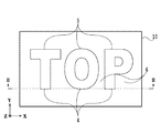
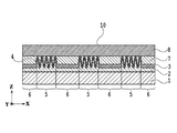
- FIG. 3 is a longitudinal sectional view taken along the line III-III of the display shown in FIG.
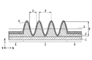
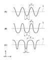
- the longitudinal cross-sectional view which shows an example of an uneven structure typically.
- the longitudinal cross-sectional view which shows another example of an uneven structure typically.
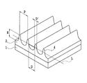
- the schematic perspective view which shows an example at the time of observing an uneven structure from the diagonal direction.
- FIG. 15 is a longitudinal sectional view taken along line XV-XV in FIG. 14.
- FIG. 18 is a longitudinal sectional view taken along line XVIII-XVIII of the display shown in FIG.
- the structure forming layer 2 is provided on one surface of the transparent substrate 1.
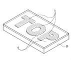
- the structure forming layer 2 includes a structural region 5 in which a concavo-convex structure 4 including a plurality of concave portions and convex portions is formed, and a non-structural region 6 in which the concavo-convex structure 4 is not formed.
- the structural region 5 can be a plurality of structural regions 5.
- the structure region 5 is configured to display the characters “TOP” in the concavo-convex structure 4.
- the plurality of structural regions 5 can be configured to display at least one selected from different patterns, characters, and numbers as an image.
- the light reflecting layer 3, the protective layer 7, and the transparent member 8 are sequentially laminated.
- a film or sheet made of a resin having high light transmittance such as polyethylene terephthalate (PET), polycarbonate (PC), and triacetyl cellulose (TAC) is preferable.
- PET polyethylene terephthalate
- PC polycarbonate
- TAC triacetyl cellulose
- a resin having a visible light wavelength transparency can be used as the material of the structure forming layer 2.
- a resin having visible light transparency such as acrylic, polycarbonate, epoxy, polyethylene, and polypropylene can be used.
- a thermoplastic resin or a photocurable resin when used, a structure including the concavo-convex structure 4 on at least one surface of the transparent substrate 1 by transfer using an original plate on which an arbitrary concavo-convex structure 4 is formed.
- the formation layer 2 can be easily produced.
- the longitudinal section of the concavo-convex structure 4 is preferably in the form of a ripple pattern, and more preferably in a sinusoidal shape.
- FIG. 4 schematically shows an example of a longitudinal section of the concavo-convex structure 4.
- the height H of the concavo-convex structure 4 is a distance from the top of the convex portion of the concavo-convex structure 4 to the bottom side of the concave portion.
- the period P of the concavo-convex structure 4 is defined as the interval between the convex portions and the convex portions adjacent to the convex portions or the interval between the concave portions and the concave portions adjacent to the concave portions.
- the concave portion is a portion that is recessed toward the transparent substrate 1 from the center line L that divides the height H into two in the concave-convex structure 4 formed in the structural region 5.
- the convex portion is a portion that protrudes from the center line L that bisects the height H to the opposite side of the transparent substrate 1 in the concave-convex structure 4 formed in the structural region 5.
- the width of the concave portion and the width of the convex portion of the concavo-convex structure 4 will be described. That the width of the concave portion and the width of the convex portion are equal means that the width D of the concave portion and the width D ′ of the convex portion are equal as shown in FIG. 6A.
- the width D of the concave portion is different from the width of the convex portion, as shown in FIG. 6B, the width D of the concave portion is wider than the width D ′ of the convex portion, or FIG. As shown in the example, it means that the width D of the concave portion is narrower than the width D ′ of the convex portion.
- FIG. 7 shows an example of the concavo-convex structure 4 when the width D of the concave portion is wider than the width D ′ of the convex portion.
- the structure forming layer 2 is formed on the transparent substrate 1, and the uneven structure 4 is formed on the structure forming layer 2.
- the concavo-convex structure 4 having the concave portion width D and the convex portion width D ′ different from each other as shown in this example is an example of the concavo-convex structure 4 having a vertical cross section.
- the concavo-convex structure 4 in which the width D of the concave portion and the width D ′ of the convex portion are equal can be a further example of the concavo-convex structure having a wind-like or sinusoidal longitudinal section.
- the light reflecting layer 3 is a layer that reflects part of the light and transmits the remaining light.
- the light reflecting layer 3 increases the reflectance of the interface of the structure forming layer 2 provided with the concavo-convex structure 4 and contributes to the coloring effect of transmitted light.
- the light reflecting layer 3 can be formed from a transparent film or a metal film.
- the refractive index of the transparent film is preferably different from the refractive index of the light-transmitting structure forming layer 2.
- the transparent coating can be formed from a dielectric layer, a dielectric multilayer film, or a high refractive index material.
- the transparent film is preferably formed from a material selected from the group consisting of ZnS, TiO 2 , PbTiO 2 , ZrO, ZnTe, and PbCrO 4 having a refractive index of 2.0 or more.
- the difference in refractive index between the light-transmitting structure forming layer 2 and the transparent film is preferably 0.5 or more. When the difference in refractive index between the light-transmitting structure forming layer 2 and the transparent coating is less than 0.5, the visual effect of light emitted from the concavo-convex structure is weakened.
- the light reflecting layer 3 is selected from the group consisting of chromium, nickel, aluminum, iron, titanium, silver, gold, copper, and mixtures thereof, and alloys thereof. Can be formed from different materials.
- aluminum is suitable as a material of the light reflection layer 3.
- a method for producing the light reflection layer 3 using a metal material for example, it can be formed by a vapor deposition method such as a vacuum evaporation method or a sputtering method.
- the light reflecting layer 3 is preferably an aluminum thin film.
- An aluminum thin film has an advantage that it can be obtained at a lower cost than gold or silver.
- aluminum can be formed easily with high accuracy by either a vacuum evaporation method or a sputtering method.
- Aluminum also has an advantage of good handling when forming the light reflecting layer 3.
- the protective layer 7 has a purpose of protecting the concavo-convex structure 4 in order to protect the display body 10 from imitation or forgery of copying the shape of the concavo-convex structure 4.
- a thermosetting or ultraviolet curable transparent adhesive can also be used.
- it can be formed from thermoplastic resins such as polypropylene resin, polyethylene terephthalate resin, polyacetal resin, and polyester resin.
- the transparent member 8 can be further adhered and protected to the surface of the protective layer 7 that is not in contact with the light reflecting layer 3.
- the transparent member 8 a film or sheet made of a light-transmitting resin such as polyethylene terephthalate (PET), polycarbonate (PC), or triacetyl cellulose (TAC) having the same light transmission as the transparent substrate 1 is used. Is preferred. Moreover, you may use inorganic materials, such as glass.
- the transparent member 8 can also prevent imitation or forgery of copying the shape of the uneven structure 4. Further, as the transparent member 8, securities such as gift certificates, passports, package members, and the like can be assumed. In the present application, the transparent member 8 is a preferred layer.
- wavelengths other than the specific wavelength hardly interfere with the surface on the opposite side of the light source 22 because interference that cancels out at each wavefront occurs. This means that the wavelength of light transmitted to the surface opposite to the light source can be controlled by controlling the optical distance of the thin film.
- the optical distance of the structure forming layer 2 and the light reflecting layer 3 with respect to the incident light can be changed. it can. Therefore, incident light from a specific angle can be emitted as transmitted light having a specific wavelength on the surface opposite to the light source. This makes it possible to observe a color watermark pattern different from, for example, a conventional black and white watermark pattern.
- the optical distance TO changes.
- the height H of the concavo-convex structure 4 is high (large)
- the light incident on the structure region 5 is easily absorbed.
- the intensity of the reflected light from the structure region 5 decreases.
- the intensity and brightness of the reflected light are low, so that the reflected light is visually recognized as a dark gray to black area.
- the incident light is hardly absorbed. Therefore, the intensity of the reflected light from the structural region 5 increases.
- the intensity and brightness of the reflected light are high, so that the reflected light is visually recognized as a light gray to gray area.
- the structural region 5 exhibits a blue-purple to blue color when observing transmitted light from the structural region 5. This is based on the action of transmitting light having a main wavelength in a short wavelength region (about 380 nm to 480 nm).
- the structural region 5 exhibits yellow to red. This is based on the action of transmitting light having a main wavelength in the long wavelength region (about 580 nm to 680 nm).
- FIG. 5 schematically shows another example of the longitudinal section of the concavo-convex structure 4.
- the optical distance TO changes.
- the light incident on the structural region 5 is easily absorbed, so that the intensity of reflected light from the structural region 5 decreases.
- the brightness is low because the reflected light intensity is low.
- the region is visually recognized as a dark gray to black region, but the luminance is low even under the condition where the diffracted light is observed.
- the intensity of reflected light from the structure region 5 is increased because incident light is difficult to be absorbed.
- the reflected light from the structure region 5 is observed, the brightness increases because the reflected light intensity is high. Under the condition where the diffracted light is not observed, it is visually recognized as a light gray to gray region, but under the condition where the diffracted light is observed, the luminance is higher.
- the concavo-convex structure 4 when observing transmitted light, almost no transmitted light is observed by the light reflecting layer 3 in the case of the concavo-convex structure 4 having a height of 200 nm or less. On the other hand, in the concavo-convex structure 4 having a height of 250 nm to 600 nm, a part of the light is transmitted and observed even if the light reflecting layer 3 is provided.
- a plurality of concavo-convex structures 4 having different heights are provided in one structural region 5 to produce a display body that has both a high effect in transmission observation and a high effect of diffracted light in reflection observation. It becomes possible.
- the plurality of structural regions 5 are different from each other with respect to the height of the concavo-convex structure 4, it is possible to transmit light having different main wavelengths for each of the plurality of structural regions 5. This makes it possible to produce a display body that exhibits a plurality of colors when the transmitted light is observed.
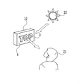
- FIG. 9 is an example when the observer 21 observes the reflected light from the display body 10 of the light source 22.
- a structure such as a diffraction grating having a sinusoidal longitudinal cross section is used as the concavo-convex structure 4
- diffracted light can be observed according to the following formula (2).
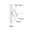
- FIG. 10 shows the positional relationship between the light incident on the diffraction grating (incident light I) and the light emitted from the diffraction grating (emitted light O).
- the period of the diffraction grating is P
- the wavelength of the incident light I is ⁇
- m is the diffraction order
- the incident angle to the structure is ⁇
- the emission angle of the m-th order diffracted light is ⁇
- diffracted light having a specific wavelength ⁇ can be observed within the range calculated by the equation (2). From the equation (2), it can be seen that the wavelength of the diffracted light changes by tilting the display body 10 or changing the observation angle. As a result, when the reflected diffracted light is observed, an effect of shining the structure region 5 in rainbow colors can be realized.
- the transmitted light from the structural region 5 of the display body 10 when the transmitted light from the structural region 5 of the display body 10 is observed, light having a specific wavelength can be observed as a watermark pattern. Further, when the reflected light from the structural region 5 of the display body 10 is observed, the diffracted light can be visually recognized within the range of characteristics, and when the display body 10 is tilted or the observation angle is changed, the diffracted light shines in rainbow colors. An effect is obtained.
- the period P of the uneven structure 4 is changed.
- the period P of the concavo-convex structure 4 provided in the structure region 5 is short, when the transmitted light from the structure region 5 is observed, it was found that the structure region 5 exhibits blue-violet to blue. This is based on the action of transmitting light having a main wavelength in a short wavelength region (about 380 nm to 480 nm).
- the period P of the concavo-convex structure 4 provided in the structure region 5 is long, it was found that the structure region 5 exhibits yellow to red color when the transmitted light from the structure region 5 is observed. This is based on the action of transmitting light having a main wavelength in the long wavelength region (about 580 nm to 680 nm). Thus, by changing the period P of the concavo-convex structure 4, the main wavelength of the light transmitted through the structural region 5 can be changed.
- the main wavelength of light transmitted through each structure region can be changed. Thereby, it is also possible to manufacture the display body 10 that exhibits a plurality of colors when the transmitted light is observed.
- the width D of the concave portion and the width D ′ of the convex portion of the uneven structure 4 are changed. It has been discovered that the main wavelength of transmitted light is shifted by changing the widths of the concave and convex portions of the concavo-convex structure 4.
- the concave and convex portions of the concavo-convex structure 4 have the same width (an example is shown in FIG. 6A)
- the dominant wavelength of light transmitted through the structural region 5 is the height H of the concavo-convex structure 4 as described above. It is arbitrarily determined according to the period P.
- the main wavelength of light transmitted through the structural region 5 is the case where the width of the concave portion and the convex portion of the concavo-convex structure 4 is equal. As compared with the chromaticity diagram, it shifts counterclockwise on the chromaticity diagram.
- the main wavelength of light transmitted through the structural region 5 is equal to the width of the concave portion and the convex portion of the concavo-convex structure 4. Compared to the case, it shifts in the clockwise direction on the chromaticity diagram.
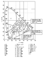
- the direction of wavelength shift means the direction in which the hue on the chromaticity diagram as shown in FIG. 11 changes. As shown in FIG. 11, for example, consider a case where the main wavelength of transmitted light is red when the concave and convex portions of the concavo-convex structure 4 having a predetermined period P and height H are equal.
- the dominant wavelength of transmitted light is It shifts counterclockwise on the chromaticity diagram and becomes yellowish red to yellowish.
- the action of shifting the dominant wavelength of transmitted light can be obtained.
- the widths of the concave and convex portions of the concavo-convex structure 4 are changed, the reflection diffraction angle and the reflection diffraction wavelength hardly change. Therefore, as long as the period P is the same as long as the diffracted light or the diffracted light can be observed, light having substantially the same wavelength can be observed as reflected diffracted light.
- the period P is 300 nm to 800 nm and the height H is 100 nm to 600 nm. A light coloring effect can be expected.
- the concavo-convex structure 4 has a wind-like vertical section.
- a plurality of structural regions 5 are provided in which the period P and the height H are constant and only the widths of the concave portions or the convex portions of the concave-convex structure 4 are different.
- the reflected light when the reflected light is observed, it is visually recognized as a region exhibiting almost the same color, but it is also possible to produce the display body 10 that exhibits a different color only when the transmitted light is observed.
- Table 1 summarizes what effect occurs on reflected light and transmitted light when the period P, height H, width of the concave portion, and width of the convex portion of the concavo-convex structure fluctuate. is there.
- the wavelength of the transmitted light becomes a short wavelength region, and the reflected light becomes reflected light with increased transmitted light intensity.
- the wavelength of the transmitted light becomes a long wavelength region and the chromaticity diagram behaves so as to go around from the short wavelength region to the long wavelength region. Show. Further, the reflected light has effects such as an increase in diffraction angle and a shift of the diffraction wavelength to a short wavelength region.
- the wavelength of the transmitted light becomes a short wavelength region, and the reflected light becomes reflected light with increased transmitted light intensity.
- the wavelength of the transmitted light becomes a long wavelength region, and the chromaticity diagram shows a behavior that goes around from the short wavelength region to the long wavelength region. Further, the reflected light has effects such as a decrease in diffraction angle and a shift of the diffraction wavelength to a long wavelength region.
- the width of the concave portion is widened (the width of the convex portion is narrowed)
- the wavelength of transmitted light is shifted in the counterclockwise direction on the chromaticity diagram as compared with the case where the width of the concave portion and the width of the convex portion are equal.
- the width of the concave portion is narrowed (the width of the convex portion is widened)
- the wavelength of transmitted light shifts in the clockwise direction on the chromaticity diagram as compared with the case where the width of the concave portion and the width of the convex portion are equal.
- the main effect on the reflected light is that diffracted light is emitted according to the period P.
- the width of the concave portion and the width of the convex portion are equal, when the width of the concave portion is wide (the width of the convex portion is narrow), When the width is narrow (the width of the convex portion is wide), the diffraction angle and the diffraction wavelength are almost constant in any case.
- the display body 10 has a plurality of structure regions 5, and each of the plurality of structure regions 5 is arranged so as to display an image such as a picture, a character, a number, and the like,
- the at least one selected from the group consisting of the period, the width of the convex portion, or the width of the concave portion may be different.
- the wavelengths (colors) of transmitted light observed from the respective structural regions 5 can be made different. It is possible to observe a plurality of color images as a watermark image instead of a simple grayscale image that is the effect of a conventional watermark.
- FIG. 12 shows an example of the display body 10 having a plurality of structural regions 5.
- a picture representing a star, a number representing “1000”, and a character representing “TOP” are formed from the structural region 5.
- the region other than the structural region 5 is composed of a non-structural region 6 in which the uneven structure 4 is not formed.
- the width D of the concave portion as shown in FIG. 6B has a cross-sectional shape wider than the width D ′ of the convex portion.
- the convex portion width D ′ and the concave portion width D have the same cross-sectional shape as shown in FIG. 6A. Use structure.
- the width D of the concave portion as shown in an example in FIG. 6C has a cross-sectional shape narrower than the width D ′ of the convex portion.
- the structure is used.
- the display body 10 is manufactured such that the light transmitted through the star pattern portion is visually recognized as green, the light transmitted through the numeral “1000” is viewed as yellow, and the light transmitted through the character “TOP” is viewed as red. Is also possible.
- the light transmittance of the non-structure region 6 is 20% or less, when observing the transmitted light through the non-structure region 6, the observer can visually recognize the non-structure region 6 from gray to black. In this case, contrast with the colored transmitted light observed from the structure region 5 can be given. In this way, it is possible to more effectively use the transmitted light coloring effect in the structural region 5.
- the light transmittance of the non-structure region 6 can be controlled by the thickness of the light reflecting layer 3 formed on the surface of the structure forming layer 2 that is not in contact with the transparent substrate 1. The explanation is described below.
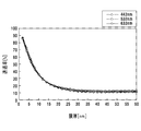
- FIG. 13 is a graph showing the thickness dependence of the transmittance at wavelengths 442 nm, 532 nm, and 633 nm when an aluminum thin film is formed on the structure forming layer 2 (refractive index 1.5).
- the transmittance at wavelengths of 442 nm, 532 nm, and 633 nm shows a value of 20% or less.
- the thickness of the aluminum thin film as the light reflecting layer 3 disposed on the non-structure region 6 is preferably 20 nm or more.
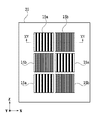
- the display body 20 shown in FIGS. 14 and 15 is formed by sequentially laminating a light transmissive structure forming layer 12, a light reflecting layer 13, an adhesive protective layer 17, and a transparent member 18 on one surface of the transparent substrate 11. It is comprised by doing.
- the structure forming layer 12 includes a plurality of structural regions 15 a and 15 b and a non-structural region 16.
- the transparent substrate 11, the light-transmitting structure forming layer 12, the light reflecting layer 13, and the protective layer 17 having adhesive properties are respectively the transparent substrate 1, the structure forming layer 2, the light reflecting layer 3, and the protective layer described above. 7 can be used.
- the structure forming layer 12 includes a plurality of structural regions 15 a and 15 b and a non-structural region 16.
- the structure forming layer 12 includes the three structural regions 15a and the three structural regions 15b.
- the number of the structural regions is not limited to six.
- the structure areas 15a and 15b are arranged in a checkered pattern, the arrangement of the structure areas is not limited to this.
- the region in which the transmitted light 24 having the wavelength corresponding to the equation 1 can be observed depends on the size of the light source 22.
- the region where the observer 21 can observe the transmitted light 24 transmitted through the image display body 10 is only one minute point corresponding to the size of the light source 22.
- a light source 22 corresponding to the size of the image is required.
- an instrument such as a light table that can irradiate the entire image display portion of the display body 10 with incident light is required.
- the transparent member 18 has light scattering properties.
- Light incident on the transparent member 18 is scattered in the transparent member 18.
- the wavefront of the transmitted light is formed by superimposing the wavefronts of a plurality of light beams that are transmitted after the reflection is repeated an even number of times inside the display body 20.
- the point where the region where 21 can be observed does not depend on the size of the light source 22 does not occur.
- At least one of the transparent substrate 11, the structure forming layer 12, or the protective layer 17 having adhesiveness has light scattering properties. In this case as well, it is possible to observe a colored watermark image without depending on the illumination environment such as the position and size of the light source 22.
- the shape of the concavo-convex structure is made different from each other by the plurality of structural regions being different with respect to at least one selected from the group consisting of the height of the concavo-convex structure, the period, the width of the concave portion and the width of the convex portion Can do.
- each structural region is regarded as a pixel in the image, transmitted light of various colors can be emitted from each structural region. In this manner, a colorful image having a plurality of colors on the same plane can be displayed.
- the concave or convex portion of the concavo-convex structure may be a linear structure. Furthermore, a diffraction grating may be used.
- the exit angle of the diffracted light varies depending on the wavelength.
- a diffraction grating is observed under a white illumination light source such as the sun or a fluorescent lamp, white light is dispersed, and light of a single wavelength is emitted at different angles, and appears to change to a rainbow color depending on the observation angle.
- transmitted light is transmitted from the transmitted light side (protective layer side).
- transmitted light when observing, it can be observed as transmitted light of different colors, while when observing reflected light (diffracted light) from the incident light side (transparent substrate side), it can be observed as reflected light of the same color.
- the wavelength of the emitted light (diffracted light) emitted from the diffraction grating is determined by the grating constant of the diffraction grating from Equation 2 as described above. In this way, it is possible to provide a display body that can observe different images for transmission observation and reflection observation.
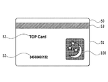
- FIG. 16 schematically shows an example of an information medium including the display body of the present invention.
- An information medium 50 shown in FIG. 16 is, for example, a magnetic card, and a printed layer 52 and a strip-shaped magnetic recording layer 53 are formed on a base material 51 on the card.
- the base material 51 is made of, for example, plastic.
- the display body 100 mentioned above is stuck to the base material 51 for anti-counterfeiting.
- the information medium 50 includes the display body 100. Therefore, forgery or imitation of this information medium 50 is difficult. Moreover, if the base material 51 is light-transmitting, a colored watermark image can be observed. Therefore, the base material 51 of the information medium 50 is preferably light transmissive.
- Example 1 17 and 18 schematically show examples of the display body of the present invention.
- the display body 10 has a polyethylene terephthalate (PET) film as the transparent substrate 1, an ultraviolet curable resin as the structure forming layer 2, and a period P and height H on the order of several hundred nm as the concavo-convex structure 4 arranged in the structure region 5.
- PET polyethylene terephthalate
- a diffraction grating is provided.
- a plurality of structure regions 5 are provided, and each concavo-convex structure 4 has a different period P and height H.
- the structure region 5 is formed of a star shape, a crescent-shaped picture or the like. Note that the structure region 5 may have an arbitrary shape. Further, as a method of forming a diffraction grating used for the concavo-convex structure 4, a laser exposure interference system may be used, or it may be formed by electron beam drawing or the like.
- the light reflecting layer 3 was formed by forming an aluminum vapor deposition layer by a vacuum vapor deposition method. At that time, vapor deposition was performed using a mask that covers the non-structural region 6 where the uneven structure 4 is not formed so that the aluminum vapor deposition layer is provided only in the structural region 5.
- thermosetting adhesive that is cured by heat was used as the protective layer 7.
- the display body 10 integrated with the transparent member 8 was obtained by bonding the transparent member 8 and the protective layer 7 together.
- a PET film having a thickness larger than that of the transparent substrate 1 was used as the transparent member 8.
- the symbols 9a and 9b were formed with printing ink in a range where the protective layer 7 of the transparent member 8 was not adhered.
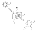
- the transmitted light transmitted from the display 10 shown in FIG. 17 was observed in the positional relationship as shown in FIG.
- Light transmitted through the structural region 5 was observed in a specific color.
- the symbol 9a and the character 9b formed with the printing ink on the non-structure region 6 and the transparent member 8 were observed as black and white grayscale images. Therefore, the light transmitted through the structural region 5 was emphasized and visually recognized.
- the display body 10 shown in FIG. 17 when the display body 10 shown in FIG. 17 is observed in the positional relationship as shown in FIG. 9, the colors of the symbols 9a and the characters 9b formed on the transparent member 8 with the printing ink are visually recognized. Furthermore, diffracted light from the diffraction grating formed in the structural region 5 could be observed at a specific observation angle. When the display body 10 is tilted or the observation angle is changed, the wavelength of the diffracted light that can be observed is changed, and light shining in rainbow colors can be visually recognized.
- Example 2 A polyethylene terephthalate (PET) film was used as the transparent substrate 1. An ultraviolet curable resin was used as the transparent molding layer 2. A diffraction grating having a period P of 300 to 600 nm and a height H of 100 to 500 nm was formed as the concavo-convex structure 4 arranged in the structure region 5.
- PET polyethylene terephthalate
- H height of 100 to 500 nm
- a plurality of structures obtained by combining structure regions having different heights were provided, and the periods P were formed differently.
- the diffraction grating used for the concavo-convex structure 4 was formed by electron beam drawing.
- the light reflecting layer 3 was formed by forming an aluminum vapor deposition layer using a vacuum vapor deposition method.
- a thermosetting adhesive was used as the protective layer 7.
- a transparent member 8 was formed on the protective layer 7.
- the display member 10 integrated with the transparent member 8 was obtained by bonding the transparent member 8 and the protective layer 7 together.
- the transmitted light from the display body produced in this example was observed in a positional relationship as shown in FIG. 8 as an example, the light transmitted through the structural region 5 was observed in a specific color.
- the symbols and characters formed with the printing ink on the non-structure region 6 and the transparent member 8 were observed as black and white grayscale images. Therefore, the light transmitted through the structure region 5 was emphasized and visually recognized.
- the display body of the present example when the display body of the present example was observed in the positional relationship as shown in FIG. 9 as an example, the color of the printing ink formed on the transparent member 8 was visually recognized.
- diffracted light from the diffraction grating formed in the structure region 5 could be observed at a specific observation angle.
- the wavelength of the diffracted light that can be observed changes, and the rainbow-colored light can be visually recognized.
- the present invention is not limited to the various forms and examples described above.
- the present invention includes a display body in which any additional layers are added to the display bodies shown in various forms and examples.
- the present invention includes a display body formed by selecting each element from the display bodies shown in various forms and examples and combining them.
Landscapes
- Physics & Mathematics (AREA)
- General Physics & Mathematics (AREA)
- Optics & Photonics (AREA)
- Health & Medical Sciences (AREA)
- Chemical & Material Sciences (AREA)
- Chemical Kinetics & Catalysis (AREA)
- General Chemical & Material Sciences (AREA)
- General Health & Medical Sciences (AREA)
- Toxicology (AREA)
- Engineering & Computer Science (AREA)
- Manufacturing & Machinery (AREA)
- Diffracting Gratings Or Hologram Optical Elements (AREA)
- Credit Cards Or The Like (AREA)
Abstract
La présente invention concerne un corps d'écran. Une couche de formation de structure, une couche de réflexion de lumière et une couche de protection sont séquentiellement stratifiées sur une surface d'un matériau de base transparent. La couche de réflexion de lumière réfléchit une partie de lumière et transmet le reste de la lumière, la couche de formation de structure comprenant une pluralité de régions de structure, et chacune des régions de structure étant constituée d'une structure évidée et en saillie.
Priority Applications (4)
| Application Number | Priority Date | Filing Date | Title |
|---|---|---|---|
| KR1020157027814A KR102219805B1 (ko) | 2013-03-12 | 2014-03-05 | 표시체 |
| EP14763434.9A EP2974879B1 (fr) | 2013-03-12 | 2014-03-05 | Corps d'écran |
| EP18192421.8A EP3427968B2 (fr) | 2013-03-12 | 2014-03-05 | Representation |
| US14/851,709 US10598833B2 (en) | 2013-03-12 | 2015-09-11 | Display |
Applications Claiming Priority (6)
| Application Number | Priority Date | Filing Date | Title |
|---|---|---|---|
| JP2013-049426 | 2013-03-12 | ||
| JP2013049426A JP6167574B2 (ja) | 2013-03-12 | 2013-03-12 | 表示体 |
| JP2013-118648 | 2013-06-05 | ||
| JP2013118648 | 2013-06-05 | ||
| JP2013126655 | 2013-06-17 | ||
| JP2013-126655 | 2013-06-17 |
Related Child Applications (1)
| Application Number | Title | Priority Date | Filing Date |
|---|---|---|---|
| US14/851,709 Continuation US10598833B2 (en) | 2013-03-12 | 2015-09-11 | Display |
Publications (1)
| Publication Number | Publication Date |
|---|---|
| WO2014141636A1 true WO2014141636A1 (fr) | 2014-09-18 |
Family
ID=51536316
Family Applications (1)
| Application Number | Title | Priority Date | Filing Date |
|---|---|---|---|
| PCT/JP2014/001223 Ceased WO2014141636A1 (fr) | 2013-03-12 | 2014-03-05 | Corps d'écran |
Country Status (4)
| Country | Link |
|---|---|
| US (1) | US10598833B2 (fr) |
| EP (2) | EP3427968B2 (fr) |
| KR (1) | KR102219805B1 (fr) |
| WO (1) | WO2014141636A1 (fr) |
Cited By (5)
| Publication number | Priority date | Publication date | Assignee | Title |
|---|---|---|---|---|
| JP2017083686A (ja) * | 2015-10-29 | 2017-05-18 | 凸版印刷株式会社 | 表示体、それを具備した転写箔、および表示体付き物品 |
| WO2017155049A1 (fr) * | 2016-03-11 | 2017-09-14 | 凸版印刷株式会社 | Indicateur et matière imprimée d'informations |
| CN108349291A (zh) * | 2015-12-01 | 2018-07-31 | 捷德货币技术有限责任公司 | 防伪元件和设有该防伪元件的数据载体 |
| JPWO2020209331A1 (fr) * | 2019-04-09 | 2020-10-15 | ||
| JP2021084356A (ja) * | 2019-11-28 | 2021-06-03 | 尾池工業株式会社 | 加飾フィルム成形体 |
Families Citing this family (10)
| Publication number | Priority date | Publication date | Assignee | Title |
|---|---|---|---|---|
| DE102015100520A1 (de) * | 2015-01-14 | 2016-07-28 | Leonhard Kurz Stiftung & Co. Kg | Mehrschichtkörper und Verfahren zu dessen Herstellung |
| JP6232013B2 (ja) * | 2015-06-01 | 2017-11-15 | 矢崎総業株式会社 | 表示装置 |
| KR20170031397A (ko) | 2015-09-11 | 2017-03-21 | 주식회사 만도 | 전자식 브레이크 시스템 |
| WO2017131089A1 (fr) * | 2016-01-27 | 2017-08-03 | 凸版印刷株式会社 | Stratifié, procédé de production de stratifié et support d'authentification personnel |
| AU2017218312A1 (en) * | 2016-02-09 | 2018-08-23 | Toppan Printing Co., Ltd. | Optical element and information recording medium for counterfeit prevention |
| JP6662333B2 (ja) * | 2017-03-14 | 2020-03-11 | オムロン株式会社 | 表示装置 |
| KR102713028B1 (ko) * | 2018-08-08 | 2024-10-07 | 도판 홀딩스 가부시키가이샤 | 개인 식별 매체 |
| DE102019003214A1 (de) * | 2019-05-07 | 2020-11-12 | Giesecke+Devrient Currency Technology Gmbh | Dekorelement mit Mehrschichtaufbau und Dekoreinrichtung |
| JP7488783B2 (ja) | 2021-03-17 | 2024-05-22 | シチズン時計株式会社 | 装飾部品の製造方法、装飾部品及び時計 |
| DE102023125600A1 (de) | 2023-09-21 | 2025-03-27 | Giesecke+Devrient Currency Technology Gmbh | Verfahren zum Herstellen eines Sicherheitselementes mit Reliefstruktur und Sicherheitselement mit Reliefstruktur |
Citations (11)
| Publication number | Priority date | Publication date | Assignee | Title |
|---|---|---|---|---|
| US5058992A (en) | 1988-09-07 | 1991-10-22 | Toppan Printing Co., Ltd. | Method for producing a display with a diffraction grating pattern and a display produced by the method |
| JPH0813568B2 (ja) | 1991-11-22 | 1996-02-14 | 大蔵省印刷局長 | 潜像を施した表裏模様合成印刷物及びその作製方法 |
| JP2615401B2 (ja) | 1992-06-04 | 1997-05-28 | 大蔵省印刷局長 | 偽造防止用潜像模様形成体及びその作製方法 |
| JP2751721B2 (ja) | 1992-03-26 | 1998-05-18 | 凸版印刷株式会社 | 回折格子パターンを有するディスプレイ |
| JP2840724B2 (ja) | 1989-07-21 | 1998-12-24 | 大蔵省印刷局長 | 虹彩色を有する透かし文様作成法及びその製品 |
| JP2010044267A (ja) * | 2008-08-14 | 2010-02-25 | Toppan Printing Co Ltd | 表示体、粘着ラベル、転写箔及びラベル付き物品 |
| JP2010286722A (ja) * | 2009-06-12 | 2010-12-24 | Toppan Printing Co Ltd | 表示体及びラベル付き物品 |
| JP2011002491A (ja) * | 2009-06-16 | 2011-01-06 | Toppan Printing Co Ltd | 表示体及びラベル付き物品 |
| JP2011118035A (ja) | 2009-12-01 | 2011-06-16 | Toppan Printing Co Ltd | 表示体及びラベル付き物品 |
| JP2012203141A (ja) * | 2011-03-24 | 2012-10-22 | Toppan Printing Co Ltd | 表示体及びラベル付き物品 |
| JP2012206352A (ja) * | 2011-03-29 | 2012-10-25 | Toppan Printing Co Ltd | 表示体及びラベル付き物品 |
Family Cites Families (33)
| Publication number | Priority date | Publication date | Assignee | Title |
|---|---|---|---|---|
| JPH02135101A (ja) | 1988-11-17 | 1990-05-24 | Ebara Corp | 高密度流体を用いる抽出分離法 |
| US5856048A (en) * | 1992-07-27 | 1999-01-05 | Dai Nippon Printing Co., Ltd. | Information-recorded media and methods for reading the information |
| DE4334847A1 (de) | 1993-10-13 | 1995-04-20 | Kurz Leonhard Fa | Wertdokument mit Fenster |
| JP2866807B2 (ja) | 1994-07-02 | 1999-03-08 | 有限会社福永博建築研究所 | 集合住宅の配管方法および胴縁並びにパイプシャフト |
| US6582422B2 (en) * | 2001-10-03 | 2003-06-24 | Bausch & Lomb Incorporated | Ophthalmic delivery device |
| US8363323B2 (en) * | 2002-04-03 | 2013-01-29 | De La Rue International Limited | Optically variable security device and method |
| DE10216562C1 (de) | 2002-04-05 | 2003-12-11 | Ovd Kinegram Ag Zug | Sicherheitselement mit Mikro- und Makrostrukturen |
| JP4564381B2 (ja) | 2004-03-10 | 2010-10-20 | 大日本印刷株式会社 | ホログラム転写箔およびその製造方法 |
| DE102004016596B4 (de) † | 2004-04-03 | 2006-07-27 | Ovd Kinegram Ag | Sicherheitselement in Form eines mehrschichtigen Folienkörpers und Verfahren zur Herstellung eines Sicherheitselements |
| DE102004042136B4 (de) | 2004-08-30 | 2006-11-09 | Ovd Kinegram Ag | Metallisiertes Sicherheitselement |
| DE102005028162A1 (de) | 2005-02-18 | 2006-12-28 | Giesecke & Devrient Gmbh | Sicherheitselement und Verfahren zu seiner Herstellung |
| DE102005017169B4 (de) | 2005-04-13 | 2023-06-22 | Ovd Kinegram Ag | Transferfolie |
| RU2443004C2 (ru) | 2006-05-02 | 2012-02-20 | Холограм Индастрис | Защитный маркировочный оптический элемент, способ изготовления такого элемента, система, содержащая такой элемент, и считывающее устройство для проверки такого элемента |
| JP5133993B2 (ja) * | 2006-09-01 | 2013-01-30 | キャボット コーポレイション | 表面処理された金属酸化物粒子 |
| JP4961944B2 (ja) | 2006-10-24 | 2012-06-27 | 凸版印刷株式会社 | 表示体及び印刷物 |
| DE102007005884B4 (de) | 2007-02-07 | 2022-02-03 | Leonhard Kurz Stiftung & Co. Kg | Sicherheitsdokument |
| DE102007039996B4 (de) | 2007-02-07 | 2020-09-24 | Leonhard Kurz Stiftung & Co. Kg | Sicherheitselement für ein Sicherheitsdokument und Verfahren zu seiner Herstellung |
| DE102007040865A1 (de) | 2007-05-04 | 2008-11-06 | Giesecke & Devrient Gmbh | Sicherheitspapier |
| US20090141355A1 (en) * | 2007-09-25 | 2009-06-04 | Opsec Security Group, Inc. | Security device, reflective layer therefor, and associated method |
| DE102008029158A1 (de) | 2007-12-21 | 2009-06-25 | Giesecke & Devrient Gmbh | Sicherheitselement |
| CN101910876A (zh) * | 2008-04-18 | 2010-12-08 | 凸版印刷株式会社 | 显示体及带标签物品 |
| DE102008024147B4 (de) | 2008-05-19 | 2020-12-03 | Ovd Kinegram Ag | Optisches Sicherheitselement |
| AU2009201481A1 (en) * | 2008-07-29 | 2010-02-18 | Visy R & D Pty Ltd | Box lid and blank therefor |
| DE102009008853A1 (de) | 2009-02-13 | 2010-08-19 | Giesecke & Devrient Gmbh | Durchsichtssicherheitselement |
| DE102009040975A1 (de) | 2009-09-11 | 2011-03-24 | Ovd Kinegram Ag | Mehrschichtkörper |
| WO2011065160A1 (fr) | 2009-11-27 | 2011-06-03 | 凸版印刷株式会社 | Affichage et objet équipé de celui-ci |
| DE102009056933A1 (de) | 2009-12-04 | 2011-06-09 | Giesecke & Devrient Gmbh | Sicherheitselement mit Farbfilter, Wertdokument mit so einem solchen Sicherheitselement sowie Herstellungsverfahren eines solchen Sicherheitselementes |
| DE102010050031A1 (de) | 2010-11-02 | 2012-05-03 | Ovd Kinegram Ag | Sicherheitselement und Verfahren zur Herstellung eines Sicherheitselements |
| EP2650124B1 (fr) * | 2010-12-09 | 2019-05-15 | Asahi Kasei Kabushiki Kaisha | Stratifié à structure fine, procédé de préparation d'un stratifié à structure fine et procédé de production d'un stratifié à structure fine |
| FR2973917B1 (fr) | 2011-04-08 | 2014-01-10 | Hologram Ind | Composant optique de securite a effet transmissif, fabrication d'un tel composant et document securise equipe d'un tel composant |
| EP2790042B2 (fr) | 2011-12-07 | 2020-01-15 | Toppan Printing Co., Ltd. | Corps d'affichage, feuille de transfert et article doté du corps d'affichage |
| DE102012110630A1 (de) | 2012-11-06 | 2014-05-08 | Ovd Kinegram Ag | Mehrschichtkörper sowie Verfahren zur Herstellung eines Sicherheitselements |
| US9827804B2 (en) * | 2014-05-13 | 2017-11-28 | Toppan Printing Co., Ltd. | Diffraction structure transfer foil and forgery prevention medium using same |
-
2014
- 2014-03-05 EP EP18192421.8A patent/EP3427968B2/fr active Active
- 2014-03-05 WO PCT/JP2014/001223 patent/WO2014141636A1/fr not_active Ceased
- 2014-03-05 KR KR1020157027814A patent/KR102219805B1/ko active Active
- 2014-03-05 EP EP14763434.9A patent/EP2974879B1/fr active Active
-
2015
- 2015-09-11 US US14/851,709 patent/US10598833B2/en active Active
Patent Citations (11)
| Publication number | Priority date | Publication date | Assignee | Title |
|---|---|---|---|---|
| US5058992A (en) | 1988-09-07 | 1991-10-22 | Toppan Printing Co., Ltd. | Method for producing a display with a diffraction grating pattern and a display produced by the method |
| JP2840724B2 (ja) | 1989-07-21 | 1998-12-24 | 大蔵省印刷局長 | 虹彩色を有する透かし文様作成法及びその製品 |
| JPH0813568B2 (ja) | 1991-11-22 | 1996-02-14 | 大蔵省印刷局長 | 潜像を施した表裏模様合成印刷物及びその作製方法 |
| JP2751721B2 (ja) | 1992-03-26 | 1998-05-18 | 凸版印刷株式会社 | 回折格子パターンを有するディスプレイ |
| JP2615401B2 (ja) | 1992-06-04 | 1997-05-28 | 大蔵省印刷局長 | 偽造防止用潜像模様形成体及びその作製方法 |
| JP2010044267A (ja) * | 2008-08-14 | 2010-02-25 | Toppan Printing Co Ltd | 表示体、粘着ラベル、転写箔及びラベル付き物品 |
| JP2010286722A (ja) * | 2009-06-12 | 2010-12-24 | Toppan Printing Co Ltd | 表示体及びラベル付き物品 |
| JP2011002491A (ja) * | 2009-06-16 | 2011-01-06 | Toppan Printing Co Ltd | 表示体及びラベル付き物品 |
| JP2011118035A (ja) | 2009-12-01 | 2011-06-16 | Toppan Printing Co Ltd | 表示体及びラベル付き物品 |
| JP2012203141A (ja) * | 2011-03-24 | 2012-10-22 | Toppan Printing Co Ltd | 表示体及びラベル付き物品 |
| JP2012206352A (ja) * | 2011-03-29 | 2012-10-25 | Toppan Printing Co Ltd | 表示体及びラベル付き物品 |
Cited By (6)
| Publication number | Priority date | Publication date | Assignee | Title |
|---|---|---|---|---|
| JP2017083686A (ja) * | 2015-10-29 | 2017-05-18 | 凸版印刷株式会社 | 表示体、それを具備した転写箔、および表示体付き物品 |
| CN108349291A (zh) * | 2015-12-01 | 2018-07-31 | 捷德货币技术有限责任公司 | 防伪元件和设有该防伪元件的数据载体 |
| WO2017155049A1 (fr) * | 2016-03-11 | 2017-09-14 | 凸版印刷株式会社 | Indicateur et matière imprimée d'informations |
| JPWO2020209331A1 (fr) * | 2019-04-09 | 2020-10-15 | ||
| JP7619260B2 (ja) | 2019-04-09 | 2025-01-22 | Toppanホールディングス株式会社 | 光学構造体、転写箔、および物品 |
| JP2021084356A (ja) * | 2019-11-28 | 2021-06-03 | 尾池工業株式会社 | 加飾フィルム成形体 |
Also Published As
| Publication number | Publication date |
|---|---|
| US20160003990A1 (en) | 2016-01-07 |
| US10598833B2 (en) | 2020-03-24 |
| EP3427968A1 (fr) | 2019-01-16 |
| EP3427968B2 (fr) | 2023-03-01 |
| EP2974879A4 (fr) | 2016-10-12 |
| EP2974879B1 (fr) | 2018-09-05 |
| KR20150128853A (ko) | 2015-11-18 |
| EP2974879A1 (fr) | 2016-01-20 |
| EP3427968B1 (fr) | 2020-03-04 |
| KR102219805B1 (ko) | 2021-02-24 |
Similar Documents
| Publication | Publication Date | Title |
|---|---|---|
| KR102219805B1 (ko) | 표시체 | |
| JP4420138B2 (ja) | 表示体及び情報印刷物 | |
| AU2013310859C1 (en) | Security element and security document | |
| JP6237759B2 (ja) | 表示体およびラベル付き物品 | |
| JP5741125B2 (ja) | 表示体及びラベル付き物品 | |
| US20230075307A1 (en) | Display element and method of determining authenticity thereof, and printed material | |
| JP5515244B2 (ja) | 表示体及びラベル付き物品 | |
| JP2010038940A (ja) | 表示体及びラベル付き物品 | |
| JP2012123102A (ja) | 表示体及びラベル付き物品 | |
| CN107531080A (zh) | 带有两个相互邻接的安全标记的安全元件 | |
| JP6136386B2 (ja) | 表示体及びその真偽判定方法 | |
| JP6413297B2 (ja) | 表示体および印刷物 | |
| JP5082378B2 (ja) | 表示体及び印刷物 | |
| JP6379547B2 (ja) | 画像表示体および情報媒体 | |
| JP5742361B2 (ja) | 表示体及び情報印刷物 | |
| JP6167574B2 (ja) | 表示体 | |
| JP5903824B2 (ja) | 偽造防止表示体及び情報印刷物 | |
| JP5834466B2 (ja) | 表示体及び情報印刷物 | |
| JP5949079B2 (ja) | 画像表示体および物品 | |
| JP5994899B2 (ja) | 表示体及びラベル付き物品 |
Legal Events
| Date | Code | Title | Description |
|---|---|---|---|
| 121 | Ep: the epo has been informed by wipo that ep was designated in this application |
Ref document number: 14763434 Country of ref document: EP Kind code of ref document: A1 |
|
| NENP | Non-entry into the national phase |
Ref country code: DE |
|
| WWE | Wipo information: entry into national phase |
Ref document number: 2014763434 Country of ref document: EP |
|
| ENP | Entry into the national phase |
Ref document number: 20157027814 Country of ref document: KR Kind code of ref document: A |