WO2014141796A1 - 二次電池状態検出装置および二次電池状態検出方法 - Google Patents
二次電池状態検出装置および二次電池状態検出方法 Download PDFInfo
- Publication number
- WO2014141796A1 WO2014141796A1 PCT/JP2014/053135 JP2014053135W WO2014141796A1 WO 2014141796 A1 WO2014141796 A1 WO 2014141796A1 JP 2014053135 W JP2014053135 W JP 2014053135W WO 2014141796 A1 WO2014141796 A1 WO 2014141796A1
- Authority
- WO
- WIPO (PCT)
- Prior art keywords
- secondary battery
- type
- equivalent circuit
- state
- circuit model
- Prior art date
- Legal status (The legal status is an assumption and is not a legal conclusion. Google has not performed a legal analysis and makes no representation as to the accuracy of the status listed.)
- Ceased
Links
Images





Classifications
-
- G—PHYSICS
- G01—MEASURING; TESTING
- G01R—MEASURING ELECTRIC VARIABLES; MEASURING MAGNETIC VARIABLES
- G01R31/00—Arrangements for testing electric properties; Arrangements for locating electric faults; Arrangements for electrical testing characterised by what is being tested not provided for elsewhere
- G01R31/36—Arrangements for testing, measuring or monitoring the electrical condition of accumulators or electric batteries, e.g. capacity or state of charge [SoC]
- G01R31/392—Determining battery ageing or deterioration, e.g. state of health
-
- G—PHYSICS
- G01—MEASURING; TESTING
- G01R—MEASURING ELECTRIC VARIABLES; MEASURING MAGNETIC VARIABLES
- G01R31/00—Arrangements for testing electric properties; Arrangements for locating electric faults; Arrangements for electrical testing characterised by what is being tested not provided for elsewhere
- G01R31/36—Arrangements for testing, measuring or monitoring the electrical condition of accumulators or electric batteries, e.g. capacity or state of charge [SoC]
- G01R31/3644—Constructional arrangements
- G01R31/3648—Constructional arrangements comprising digital calculation means, e.g. for performing an algorithm
-
- H—ELECTRICITY
- H01—ELECTRIC ELEMENTS
- H01M—PROCESSES OR MEANS, e.g. BATTERIES, FOR THE DIRECT CONVERSION OF CHEMICAL ENERGY INTO ELECTRICAL ENERGY
- H01M10/00—Secondary cells; Manufacture thereof
- H01M10/42—Methods or arrangements for servicing or maintenance of secondary cells or secondary half-cells
- H01M10/48—Accumulators combined with arrangements for measuring, testing or indicating the condition of cells, e.g. the level or density of the electrolyte
-
- H—ELECTRICITY
- H02—GENERATION; CONVERSION OR DISTRIBUTION OF ELECTRIC POWER
- H02J—ELECTRIC POWER NETWORKS; CIRCUIT ARRANGEMENTS OR SYSTEMS FOR SUPPLYING OR DISTRIBUTING ELECTRIC POWER; SYSTEMS FOR STORING ELECTRIC ENERGY
- H02J7/00—Circuit arrangements for charging or discharging batteries or for supplying loads from batteries
- H02J7/50—Circuit arrangements for charging or discharging batteries or for supplying loads from batteries acting upon multiple batteries simultaneously or sequentially
-
- H—ELECTRICITY
- H02—GENERATION; CONVERSION OR DISTRIBUTION OF ELECTRIC POWER
- H02J—ELECTRIC POWER NETWORKS; CIRCUIT ARRANGEMENTS OR SYSTEMS FOR SUPPLYING OR DISTRIBUTING ELECTRIC POWER; SYSTEMS FOR STORING ELECTRIC ENERGY
- H02J7/00—Circuit arrangements for charging or discharging batteries or for supplying loads from batteries
- H02J7/80—Circuit arrangements for charging or discharging batteries or for supplying loads from batteries including monitoring or indicating arrangements
-
- H—ELECTRICITY
- H02—GENERATION; CONVERSION OR DISTRIBUTION OF ELECTRIC POWER
- H02J—ELECTRIC POWER NETWORKS; CIRCUIT ARRANGEMENTS OR SYSTEMS FOR SUPPLYING OR DISTRIBUTING ELECTRIC POWER; SYSTEMS FOR STORING ELECTRIC ENERGY
- H02J7/00—Circuit arrangements for charging or discharging batteries or for supplying loads from batteries
- H02J7/80—Circuit arrangements for charging or discharging batteries or for supplying loads from batteries including monitoring or indicating arrangements
- H02J7/84—Control of state of health [SOH]
-
- G—PHYSICS
- G01—MEASURING; TESTING
- G01R—MEASURING ELECTRIC VARIABLES; MEASURING MAGNETIC VARIABLES
- G01R31/00—Arrangements for testing electric properties; Arrangements for locating electric faults; Arrangements for electrical testing characterised by what is being tested not provided for elsewhere
- G01R31/36—Arrangements for testing, measuring or monitoring the electrical condition of accumulators or electric batteries, e.g. capacity or state of charge [SoC]
- G01R31/367—Software therefor, e.g. for battery testing using modelling or look-up tables
-
- G—PHYSICS
- G01—MEASURING; TESTING
- G01R—MEASURING ELECTRIC VARIABLES; MEASURING MAGNETIC VARIABLES
- G01R31/00—Arrangements for testing electric properties; Arrangements for locating electric faults; Arrangements for electrical testing characterised by what is being tested not provided for elsewhere
- G01R31/36—Arrangements for testing, measuring or monitoring the electrical condition of accumulators or electric batteries, e.g. capacity or state of charge [SoC]
- G01R31/382—Arrangements for monitoring battery or accumulator variables, e.g. SoC
- G01R31/3842—Arrangements for monitoring battery or accumulator variables, e.g. SoC combining voltage and current measurements
-
- G—PHYSICS
- G01—MEASURING; TESTING
- G01R—MEASURING ELECTRIC VARIABLES; MEASURING MAGNETIC VARIABLES
- G01R31/00—Arrangements for testing electric properties; Arrangements for locating electric faults; Arrangements for electrical testing characterised by what is being tested not provided for elsewhere
- G01R31/36—Arrangements for testing, measuring or monitoring the electrical condition of accumulators or electric batteries, e.g. capacity or state of charge [SoC]
- G01R31/389—Measuring internal impedance, internal conductance or related variables
-
- H—ELECTRICITY
- H02—GENERATION; CONVERSION OR DISTRIBUTION OF ELECTRIC POWER
- H02J—ELECTRIC POWER NETWORKS; CIRCUIT ARRANGEMENTS OR SYSTEMS FOR SUPPLYING OR DISTRIBUTING ELECTRIC POWER; SYSTEMS FOR STORING ELECTRIC ENERGY
- H02J7/00—Circuit arrangements for charging or discharging batteries or for supplying loads from batteries
- H02J7/80—Circuit arrangements for charging or discharging batteries or for supplying loads from batteries including monitoring or indicating arrangements
- H02J7/82—Control of state of charge [SOC]
-
- Y—GENERAL TAGGING OF NEW TECHNOLOGICAL DEVELOPMENTS; GENERAL TAGGING OF CROSS-SECTIONAL TECHNOLOGIES SPANNING OVER SEVERAL SECTIONS OF THE IPC; TECHNICAL SUBJECTS COVERED BY FORMER USPC CROSS-REFERENCE ART COLLECTIONS [XRACs] AND DIGESTS
- Y02—TECHNOLOGIES OR APPLICATIONS FOR MITIGATION OR ADAPTATION AGAINST CLIMATE CHANGE
- Y02E—REDUCTION OF GREENHOUSE GAS [GHG] EMISSIONS, RELATED TO ENERGY GENERATION, TRANSMISSION OR DISTRIBUTION
- Y02E60/00—Enabling technologies; Technologies with a potential or indirect contribution to GHG emissions mitigation
- Y02E60/10—Energy storage using batteries
Definitions
- the present invention relates to a secondary battery state detection device and a secondary battery state detection method.
- the secondary battery is pulse-discharged at a constant voltage a predetermined number of times at a frequency of 100 Hz or more, and a voltage difference that is a difference between a voltage before the start of the pulse discharge and a voltage immediately after the end of the pulse discharge. And the discharge capacity or the degree of deterioration of the secondary battery is determined from the voltage difference.
- JP 2009-244180 A Japanese Patent Laid-Open No. 2005-221487 JP 2007-187534 A
- an object of the present invention is to provide a secondary battery state detection device and a secondary battery state detection method that can detect the state of a plurality of secondary batteries of different types with high accuracy.
- the present invention provides a secondary battery state detection device that detects a state of a secondary battery, and a current value of a current flowing through the secondary battery and a voltage generated in the secondary battery by the current.
- Measuring means for measuring the voltage value of the secondary battery at a predetermined frequency
- optimization means for optimizing the element constant of the equivalent circuit model of the secondary battery based on the voltage value and the current value measured by the measuring means
- An identification means for identifying the type of the secondary battery with reference to the element constant of the equivalent circuit model optimized by the optimization means, and the state of the secondary battery based on the element constant of the equivalent circuit model
- Storage means for storing the detection formula for each type of the secondary battery, acquisition means for acquiring the detection formula corresponding to the type identified by the identification means from the storage means, and the acquisition means Therefore, by applying the element constants on the acquired detection type, and having a detecting means for detecting the state of the secondary battery.
- one aspect of the present invention is characterized in that the identification unit identifies the type of the secondary battery based on a mutual relationship between a plurality of element constants of the equivalent circuit model. According to such a configuration, the type of the secondary battery can be reliably identified based on the mutual relationship between the element constants.
- the identification unit compares a ratio of a plurality of element constants of the equivalent circuit model with a predetermined threshold value, and identifies the type of the secondary battery based on the magnitude relationship. It is characterized by doing. According to such a configuration, it is possible to easily determine the type of the secondary battery based on the element constant ratio.
- the identification unit compares an identification index value calculated from a plurality of element constants of the equivalent circuit model with a predetermined threshold, and based on the magnitude relationship, the secondary order The battery type is identified. According to such a configuration, the secondary battery can be more accurately identified based on the magnitude relationship between the identification index value and the threshold value.
- one aspect of the present invention is a learning model in which the identification unit receives a constant of the equivalent circuit model of the secondary battery as an input, and outputs information for specifying the type of the secondary battery, A learning model having an identification capability is provided in advance by the input / output pair, and the type of the secondary battery is identified by the learning model. According to such a configuration, it is possible to increase the identification rate by using the learning model.
- One aspect of the present invention is characterized in that the learning model is a neural network or a support vector machine. According to such a configuration, by creating a learning model having a high discrimination capability in advance, the discrimination rate of the type of secondary battery can be increased based on this learning model.
- one aspect of the present invention is characterized in that the identification means identifies whether the secondary battery is a lead battery, a nickel metal hydride battery, a lithium ion battery, or a nickel cadmium battery. And According to such a configuration, various types of secondary batteries having different structures can be identified, and the state of the identified secondary battery can be detected.
- the identification means is any of a liquid battery of a lead storage battery, a sealed battery, and an idling stop battery as the type of the secondary battery, or any of these It is characterized by identifying whether it is new or used. According to such a configuration, various types of lead storage batteries can be identified, and the state of the identified lead storage batteries can be detected.
- the detection unit detects at least one of an initial capacity, a deteriorated capacity, a remaining discharge capacity, and a response voltage with respect to a predetermined required current of the secondary battery. And According to such a configuration, it is possible to detect various states of the secondary battery, and thus various determinations can be made.
- a secondary battery state detection method for detecting a state of a secondary battery, wherein a current value of a current flowing through the secondary battery and a voltage value of a voltage generated in the secondary battery by the current are predetermined.
- An identification step for identifying the type of the secondary battery with reference to the converted element constant of the equivalent circuit model, and a detection formula for detecting the state of the secondary battery based on the element constant of the equivalent circuit model Obtaining from the storage means stored for each type of secondary battery, and applying the element constant to the detection formula obtained in the obtaining step
- the present invention it is possible to provide a secondary battery state detection device and a secondary battery state detection method that can detect the state of a plurality of secondary batteries of different types with high accuracy.
- FIG. 1st Embodiment It is a figure which shows the structural example of the secondary battery state detection apparatus which concerns on 1st Embodiment of this invention. It is a block diagram which shows the detailed structural example of the control part of FIG. It is a figure which shows the time change of the voltage and electric current at the time of rotation of a starter motor. It is a figure which shows an example of the equivalent circuit model of a secondary battery. It is a figure which shows the relationship between an equivalent circuit model and the measured secondary battery response voltage. It is a figure which shows the relationship of the constant of the secondary battery for idling stops, and a normal liquid type secondary battery. It is a flowchart for demonstrating the flow of the process performed in 1st Embodiment. It is a figure which shows the structural example of the supervised learning model used in 2nd Embodiment. It is a flowchart for demonstrating the flow of the process performed in 2nd Embodiment.
- FIG. 1 is a diagram showing a power supply system of a vehicle having a secondary battery state detection device according to the first embodiment of the present invention.
- the secondary battery state detection device 1 includes a control unit 10, a voltage sensor 11, a current sensor 12, a temperature sensor 13, and a discharge circuit 15 as main components, and detects the state of the secondary battery 14.
- the control unit 10 refers to outputs from the voltage sensor 11, the current sensor 12, and the temperature sensor 13 to detect the state of the secondary battery 14.
- the voltage sensor 11 detects the terminal voltage of the secondary battery 14 and notifies the control unit 10 of it.
- the current sensor 12 detects the current flowing through the secondary battery 14 and notifies the control unit 10 of the current.
- the temperature sensor 13 detects the secondary battery 14 itself or the surrounding environmental temperature, and notifies the control unit 10 of it.
- the discharge circuit 15 is configured by, for example, a semiconductor switch and a resistance element connected in series, and the secondary battery 14 is pulse-discharged when the control unit 10 controls the semiconductor switch to be turned on / off. Instead of discharging through the resistance element, for example, the discharge current may be made constant by discharging through a constant current circuit.
- the secondary battery 14 is constituted by, for example, a lead storage battery, a nickel cadmium battery, a nickel metal hydride battery, or a lithium ion battery, and is charged by an alternator 16 to drive a starter motor 18 and start an engine, 19 is supplied with electric power.
- the alternator 16 is driven by the engine 17 to generate AC power, convert it into DC power by a rectifier circuit, and charge the secondary battery 14.
- the engine 17 is composed of, for example, a reciprocating engine such as a gasoline engine and a diesel engine, or a rotary engine, and is started by a starter motor 18 to drive driving wheels via a transmission to provide propulsive force to the vehicle. Drive to generate power.
- the starter motor 18 is constituted by, for example, a DC motor, generates a rotational force by the electric power supplied from the secondary battery 14, and starts the engine 17.
- the load 19 is configured by, for example, an electric steering motor, a defogger, an ignition coil, a car audio, a car navigation, and the like, and operates with electric power from the secondary battery 14.
- FIG. 2 is a diagram showing a detailed configuration example of the control unit 10 shown in FIG.
- the control unit 10 includes a CPU (Central Processing Unit) 10a, a ROM (Read Only Memory) 10b, a RAM (Random Access Memory) 10c, a communication unit 10d, and an I / F (Interface) 10e.
- the CPU 10a controls each unit based on the program 10ba stored in the ROM 10b.
- the ROM 10b is configured by a semiconductor memory or the like, and stores a program 10ba and formulas described later.
- the RAM 10c is configured by a semiconductor memory or the like, and stores data generated when the program ba is executed and parameters 10ca such as mathematical formulas described later.
- the communication unit 10d communicates with an upper device such as an ECU (Electric Control Unit) and notifies the higher device of the detected information.
- the I / F 10e converts the signal supplied from the voltage sensor 11, the current sensor 12, and the temperature sensor 13 into a digital signal and takes it in, and supplies a driving current to the discharge circuit 15 to control it.
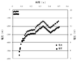
- FIG. 3 shows temporal changes in voltage and current when the starter motor 18 is rotated.
- a current of about several hundred amperes flows at the start of rotation, and the terminal voltage of the secondary battery 14 drops due to this current.
- the starter motor 18 starts to rotate, the current decreases, and this also reduces the voltage drop.
- the engine 17 starts and starts rotating, the current decreases rapidly, and when it exceeds a certain number of rotations, charging starts.
- Such changes in voltage and current are sampled at a predetermined cycle and stored in the RAM 10c.
- the CPU 10a acquires the measured values of the voltage and current stored in the RAM 10c, and optimizes the element values (Rohm, Rct1, C1, Rct2, C2) of the equivalent circuit of the secondary battery 14 shown in FIG. Turn into.
- an optimal state vector X is estimated by an extended Kalman filter operation, and an equivalent circuit is adjusted from the estimated state vector X. Update the parameter (element value) to the optimum one. Specifically, based on an equivalent circuit using an adjustment parameter obtained from a state vector X in a certain state, a voltage drop ⁇ V when the secondary battery is discharged with a predetermined current pattern is calculated, and this approaches a measured value.
- the state vector X is updated as follows. Then, an optimal adjustment parameter is calculated from the state vector X optimized by the update. Of course, you may optimize by methods other than this.
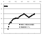
- constants are set so that the response of the equivalent circuit model and the measured value (voltage response value) of the secondary battery 14 substantially coincide. be able to.
- circles indicate actual measurement values
- squares indicate the response of the equivalent circuit model.
- the CPU 10a obtains the element value Rct1 of the resistance component and the element value C1 of the capacitance component shown in FIG. 4 from the element values of the equivalent circuit optimized as described above.
- the CPU 10a applies the acquired value of Rct1 to, for example, a predetermined function f (Rct1), and calculates an index value for identifying the type of the secondary battery 14.
- f (Rct1) for calculating the index value for example, the following formula (1) can be used.
- the CPU 10a compares the index value f (Rct1) obtained as described above with 1 / C1, and when 1 / C1 exceeds the index value f (Rct1), the secondary battery 14 is, for example, idling stopped.
- the secondary battery 14 is determined to be a dedicated secondary battery and 1 / C1 does not exceed the index value f (Rct1), the secondary battery 14 is determined to be, for example, a normal liquid type secondary battery.
- the determination is made using Rct1 and C1, but other values (for example, Rct2 and C2) may be used.
- Rct1, Rct2, C1, and C2 may be used in combination, or Rct1 and C2, and Rct2 and C1 may be used in combination.
- the horizontal axis indicates the resistance Rct
- the curve shown as the separation curve shows the index value f (Rct) described above.
- the secondary battery existing above the separation curve (upper side of the figure) is dedicated to idling stop
- the detection formula fistp () dedicated to idling stop is acquired from the ROM 10b, and is equivalent to the acquired detection formula fistp ().
- a circuit constant (element value) is substituted to detect the state of the secondary battery 14.
- the detection formula fnrml () dedicated to the normal liquid type is acquired from the ROM 10b, and an equivalent circuit of the detected detection type fnrml () is obtained. A constant is substituted and the state of the secondary battery 14 is detected.
- the state of the secondary battery 14 detected from the constant of the equivalent circuit model includes, for example, the initial capacity, the deteriorated capacity, the remaining discharge capacity, the response voltage with respect to a predetermined required current, and the like.
- the initial capacity (SOH_ini) when taken as an example, it can be calculated by the following equation.
- the constants Const 1 to 6 of the formula (2) can be optimally determined for each type of secondary battery to be identified. Different calculation formulas can be used depending on the type of the secondary battery.
- the calculation formula for correcting the temperature dependence and SOC (State Of Charge) dependence of the constants of the equivalent circuit model can be optimized for each type of secondary battery based on the same concept.
- the calculation formulas and coefficients for correction calculation are stored for each type of secondary battery and corrected using the formulas and coefficients corresponding to the identified secondary battery type. Calculations can be made.
- the type of the secondary battery 14 is identified based on the constants of the equivalent circuit model, and the detection formula corresponding to the identified type is used to Since the state of the secondary battery 14 is detected, the state can be accurately detected regardless of the type of the secondary battery 14.
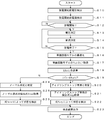
- FIG. 7 is a flowchart illustrating an example of processing executed in the first embodiment.
- the processing in this figure is executed when, for example, an ignition switch (not shown) is operated. Of course, other timings may be used.
- step S10 the CPU 10a acquires from the voltage sensor 11 a voltage before the start of discharge, that is, a voltage before the starter motor 18 starts rotating.
- step S11 the CPU 10a acquires from the current sensor 12 the current before the start of discharge, that is, the current before the starter motor 18 starts rotating.
- step S12 the CPU 10a determines whether or not the discharge is started. If it is determined that the discharge is started (step S12: Yes), the process proceeds to step S13, and otherwise (step S12: No). In such a case, the same processing is repeated. For example, when the rotation of the starter motor 18 is started, it is determined as Yes and the process proceeds to step S13.
- step S13 the CPU 10a refers to the output of the voltage sensor 11 and measures the voltage of the secondary battery 14.
- step S14 the CPU 10a refers to the output of the current sensor 12 and measures the current of the secondary battery 14.
- step S15 the CPU 10a determines whether or not the discharge has ended. If it is determined that the discharge has ended (step S15: Yes), the process proceeds to step S16, and otherwise (step S15: No). In step S13, the same processing is repeated.
- the determination as to whether or not the discharge has ended can be made, for example, by determining whether the rotation of the starter motor 18 has stopped, the engine 17 has been started, or the ignition switch has been restored from the start position. .
- step S16 the CPU 10a executes optimization of each element of the equivalent circuit model.
- an optimal state vector X is estimated by an extended Kalman filter operation, and an adjustment parameter of the equivalent circuit is estimated from the estimated state vector X. (Element value) is updated to an optimum value.
- a voltage drop ⁇ V when the secondary battery is discharged with a predetermined current pattern is calculated, and this approaches a measured value.
- the state vector X is updated as follows. Then, an optimal adjustment parameter is calculated from the state vector X optimized by the update.
- step S17 the CPU 10a acquires, for example, Rct1 and C1 among the constants of the equivalent circuit model optimized in step S16.
- step S18 the CPU 10a applies the constant Rct1 to the function f (Rct1), and calculates an index value for identifying the type of the secondary battery 14.
- the function f (Rct1) for calculating the index value for example, the above-described equation (1) can be used.
- step S19 the CPU 10a compares the index value calculated in step S18 with 1 / C1, and if 1 / C1> f (Rct1) is satisfied (step S19: Yes), the process proceeds to step S20. In the case (step S19: No), the process proceeds to step S24.
- step S20 the CPU 10a determines that the secondary battery 14 is dedicated to idling stop.
- step S21 the CPU 10a acquires a detection formula fistp dedicated to idling stop from the ROM 10b.
- the detection formula fistp dedicated to the idling stop is a formula specialized for the secondary battery dedicated to the idling stop. By using this formula, the state of the secondary battery dedicated to the idling stop can be accurately detected. .
- step S22 the CPU 10a detects the state of the secondary battery dedicated for idling stop based on the detection formula fistp acquired in step S21.
- the state to be detected includes, for example, an initial capacity, a deteriorated capacity, a remaining discharge capacity, a response voltage with respect to a predetermined required current, and the like.
- the initial capacity (SOH_ini) is taken as an example, it can be calculated by the above-described equation (2).
- step S23 the CPU 10a outputs the detection result of the secondary battery 14 calculated in step S22.
- step S24 the CPU 10a determines that the secondary battery 14 is a normal liquid type.
- step S25 the CPU 10a acquires the detection formula fnrml dedicated to the normal liquid type from the ROM 10b.
- the detection type fnrml dedicated to the normal liquid type is an expression specialized for the normal liquid type secondary battery. By using this formula, the state of the normal liquid type secondary battery can be accurately detected. it can.
- step S26 the CPU 10a detects the state of the normal liquid type secondary battery based on the detection formula fnrml acquired in step S25.
- the state to be detected includes, for example, an initial capacity, a deteriorated capacity, a remaining discharge capacity, a response voltage with respect to a predetermined required current, and the like.
- the initial capacity (SOH_ini) is taken as an example, it can be calculated by the above-described equation (2).
- the state of the normal liquid type secondary battery obtained in this way is output in step S23.
- the second embodiment has the same configuration as that of the first embodiment, but a part of the processing executed in the control unit 10 is different from that of the first embodiment. Therefore, the following description will focus on parts that are different from the first embodiment.
- the type of the secondary battery 14 is identified based on the index value f (Rct1).
- the secondary battery 14 is based on the supervised learning model. Identify the type.
- the supervised learning process for example, a neural network or a support vector machine can be used. In the following, a case where a neural network is used will be described as an example.
- a lead storage battery As a kind of secondary battery to identify, there exist a lead storage battery, a nickel metal hydride battery, a lithium ion battery, and a nickel cadmium battery, for example. Moreover, you may make it identify whether it is any of the liquid storage battery of a lead storage battery, a seal-type storage battery, and the storage battery for idling stops, or any of these new articles or used articles.
- the type of the secondary battery 14 is identified using a neural network that has been learned in advance.
- the equivalent circuit model is optimized, and the constant of the equivalent circuit shown in FIG. 4 obtained by the optimization is input to the neural network to identify the type of the secondary battery 14.
- Information is output.
- the secondary battery 14 is a lead storage battery for idling stop
- the constants Rohm, Rct1, C1, Rct2, and C2 of the elements constituting the equivalent circuit model is output.
- a detection formula corresponding to the specified type is acquired from the ROM 10b, and constants of elements constituting the equivalent circuit model are substituted into the detection formula, and the state of the secondary battery 14 is determined. Is detected.
- a detection formula corresponding to the lead-acid storage battery for idling stop is acquired from the ROM 10b, and for example, the constants Rohm, Rct1, C1, Rct2, of the elements constituting the equivalent circuit model are obtained with respect to this detection formula.
- C2 is substituted and the state of the secondary battery 14 is detected. According to such a process, it becomes possible to increase the identification rate of the type of the secondary battery as compared with the first embodiment described above. For this reason, it is possible to accurately detect the states of a plurality of types of secondary batteries.
- steps S10 to S16 as in the case described above, the voltage value and the current value when the starter motor 18 is rotated are measured at predetermined intervals and stored in the RAM 10c.
- the equivalent circuit model is optimized based on the voltage value and the current value stored in the RAM 10c.
- step S40 the CPU 10a acquires a constant of the equivalent circuit model. For example, at least a part of constants Rohm, Rct1, C1, Rct2, and C2 of the elements constituting the equivalent circuit model is acquired.
- step S41 the CPU 10a inputs the constant acquired in step S40 into a supervised learning model that has been previously learned.
- a supervised learning model exists as the supervised learning model, and in the process of step S41, the CPU 10a makes the element constants Rohm, Rct1, C1, Rct2, and C2 of the element acquired in step S40 to the neural network. At least some constants are entered.
- step S42 the CPU 10a acquires the output of the supervised learning model. For example, when a constant of the equivalent circuit of the lead-acid battery dedicated to idling stop is input, information indicating that the lead-acid battery is dedicated to idling stop is output. In step S42, this information is acquired.
- step S43 the CPU 10a acquires the detection formula f () corresponding to the output acquired in step S42 from the ROM 10b. For example, when information indicating that the lead-acid battery is dedicated to idling stop is output, the detection formula f () corresponding to the lead-acid battery dedicated to idling stop is acquired from the ROM 10b.
- step S44 the CPU 10a detects the state of the secondary battery based on the detection formula f () acquired in step S43.
- the detected state includes, for example, an initial capacity, a deteriorated capacity, a remaining discharge capacity, a response voltage with respect to a predetermined required current, and the like.
- the initial capacity (SOH_ini) is taken as an example, it can be calculated by the above-described equation (2).
- step S23 the CPU 10a outputs the state of the secondary battery obtained in step S44.
- the type of the secondary battery 14 is identified using the supervised learning model, and the state of the secondary battery 14 is detected using the detection formula corresponding to the identification result. Regardless of the type of the battery 14, it is possible to accurately detect the state.
- the type of the secondary battery 14 is determined based on the relationship between the constants Rtc1 and C1, but it may be determined using other constants. Further, instead of using two types of constants, determination may be made using three or more constants. Further, although the function shown in the expression (1) is used for identification, for example, the ratio of two constants (for example, the ratio of Rohm to Rct1) is determined by comparing with a predetermined threshold. Also good. More specifically, Rohm / Rct1, Rct1 / Rct2, Rct1 / C1,... May be identified by comparison with a threshold value obtained in advance through experiments.
- the identification index may be calculated using different calculation formulas using constants of different equivalent circuit models depending on the type of the secondary battery to be identified. Further, the identification index may be calculated using constants of a plurality of equivalent circuit models, or may be performed as a discrimination method depending on whether or not a predetermined threshold value obtained in advance through experiments or the like is exceeded.
- the type of the secondary battery 14 is determined to be the normal liquid type or the idling stop type, but other types may be determined. For example, the initial capacity, manufacturer, and model number of the secondary battery 14 may be identified.
- the case where the initial capacity (SOH_ini) of the secondary battery 14 is obtained has been described as an example.
- the deterioration capacity, the remaining discharge capacity, and a predetermined required current It is also possible to obtain the response voltage.
- a formula for obtaining these a formula similar to the formula (2) described above or a function using at least a part of the elements of the equivalent circuit model can be used.
- the type of the secondary battery 14 is identified using a neural network, but other supervised learning models may be used.
- a support vector machine may be used.
- the separation curve in the teacher data so that the minimum value of the distance from the separation curve to each sample point of the teacher data is maximized (so that the margin is maximized). Can determine a separation curve with high discrimination power.
- the constants of the equivalent circuit model are learned for a known type of secondary battery, and a separated hyperplane / hypersurface is obtained by supervised learning using the known data as teacher data.
- a method of identifying using a hyperplane or a hypersurface may be used.
- the equivalent circuit model is optimized based on changes in voltage and current when the starter motor 18 is rotated. However, based on the current flowing to a load other than the starter motor 18. May be optimized. For example, the discharge circuit 15 may be switched, the voltage and current of the secondary battery 14 at that time may be detected, and the equivalent circuit model may be optimized based on the detected voltage and current.
- the model shown in FIG. 4 is used as the equivalent circuit model.
- other equivalent circuit models may be used.
- an equivalent circuit model in which three or more stages of resistance elements and capacitance elements connected in parallel are connected in series may be used.
- other equivalent circuit models may be used.
- FIGS. 7 and 9 are examples, and the processes may be executed in an order other than this, or other processes may be executed.
- only the state detection of the secondary battery 14 is performed. For example, based on the obtained state, for example, the idling stop execution of stopping the engine 17 is stopped. You may make it control. Specifically, when the SOC of the secondary battery 14 is higher than a predetermined threshold, idling stop is executed, and when it is determined that the SOC is lower than the predetermined threshold, idling stop is not executed. Also good. Moreover, when SOH is approaching a predetermined threshold value, for example, the operation of the load 19 may be stopped to prevent further consumption of the secondary battery 14. Furthermore, when SOH is smaller than a predetermined threshold, a message instructing to replace the secondary battery 14 may be displayed.
Landscapes
- Engineering & Computer Science (AREA)
- Power Engineering (AREA)
- Physics & Mathematics (AREA)
- General Physics & Mathematics (AREA)
- Manufacturing & Machinery (AREA)
- Chemical & Material Sciences (AREA)
- Chemical Kinetics & Catalysis (AREA)
- Electrochemistry (AREA)
- General Chemical & Material Sciences (AREA)
- Secondary Cells (AREA)
- Tests Of Electric Status Of Batteries (AREA)
- Charge And Discharge Circuits For Batteries Or The Like (AREA)
Abstract
【課題】種類が異なる複数の二次電池の状態を高精度で検出すること。【解決手段】二次電池14に流れる電流の電流値と、当該電流によって二次電池に生じる電圧の電圧値を所定の頻度で測定する測定手段(電圧センサ11、電流センサ12)と、測定された電圧値および電流値に基づいて、二次電池の等価回路モデルの素子定数を最適化する最適化手段(CPU10a)と、最適化された等価回路モデルの素子定数を参照して、二次電池の種類を識別する識別手段(CPU10a)と、二次電池の状態を検出する検出式を二次電池の種類毎に格納する格納手段(ROM10b)と、識別された種類に対応する検出式を、格納手段から取得する取得手段(CPU10a)と、取得された検出式に素子定数を適用することで、二次電池の状態を検出する検出手段(CPU10a)と、を有する。
Description
本発明は、二次電池状態検出装置および二次電池状態検出方法に関するものである。
二次電池の劣化度(SOH:State Of Health)や放電能力(SOF:State Of Function)を検出するために、二次電池の内部抵抗または内部インピーダンスを用いる方法が知られている。しかし、二次電池の内部抵抗は複数の抵抗成分の合成であることから、高精度に二次電池状態を検知するためには、各抵抗成分を分解して求める必要があり、特に、反応抵抗を精度良く求める必要がある。このための技術として、例えば、特許文献1をはじめ、特許文献2,3の技術が開示されている。
ここで、特許文献1に開示された技術では、100Hz以上の周波数により二次電池を所定回数一定電圧でパルス放電させ、パルス放電の開始前の電圧と終了直後の電圧との差である電圧差を算出し、電圧差から二次電池の放電能力または劣化度を判定する。
また、特許文献2に開示された技術では、パルス放電によらず、通常の実車環境の車載二次電池の電圧/電流データを取得し、これをフーリエ変換して周波数分解し、インピーダンス・スペクトルを求める。そして、求めたインピーダンス・スペクトルを用いて対象二次電池の等価回路モデルの定数フィッティングを行い、二次電池内の抵抗成分、二重層容量成分を分解して求める。
また、特許文献3に開示された技術では、車載二次電池の電圧/電流データを取得し、カルマンフィルタ演算等を用いて対象二次電池の等価回路モデルの定数をオンライン推定し、二次電池内の抵抗成分、二重層容量成分を分解して求める。
ところで、特許文献1~3に開示された技術では、特定の二次電池のみを対象として状態を検出する場合には、高精度な検出を実現することが可能であるが、種類の異なる複数の二次電池に対応することは困難である。
そこで、本発明は、種類が異なる複数の二次電池の状態を高精度で検出することが可能な二次電池状態検出装置および二次電池状態検出方法を提供することを目的としている。
上記課題を解決するために、本発明は、二次電池の状態を検出する二次電池状態検出装置において、前記二次電池に流れる電流の電流値と、当該電流によって前記二次電池に生じる電圧の電圧値を所定の頻度で測定する測定手段と、前記測定手段によって測定された電圧値および電流値に基づいて、前記二次電池の等価回路モデルの素子定数を最適化する最適化手段と、前記最適化手段によって最適化された前記等価回路モデルの素子定数を参照して、前記二次電池の種類を識別する識別手段と、前記等価回路モデルの素子定数に基づいて前記二次電池の状態を検出する検出式を、前記二次電池の種類毎に格納する格納手段と、前記識別手段によって識別された種類に対応する検出式を、前記格納手段から取得する取得手段と、前記取得手段によって取得された前記検出式に前記素子定数を適用することで、前記二次電池の状態を検出する検出手段と、を有することを特徴とする。
このような構成によれば、種類が異なる複数の二次電池の状態を高精度で検出することが可能になる。
このような構成によれば、種類が異なる複数の二次電池の状態を高精度で検出することが可能になる。
また、本発明の一側面は、前記識別手段は、前記等価回路モデルの複数の素子定数の相互の関係に基づいて、前記二次電池の種類を識別することを特徴とする。
このような構成によれば、素子定数の相互関係に基づいて、二次電池の種類を確実に識別することができる。
このような構成によれば、素子定数の相互関係に基づいて、二次電池の種類を確実に識別することができる。
また、本発明の一側面は、前記識別手段は、前記等価回路モデルの複数の素子定数の比と、所定の閾値とを比較し、その大小関係に基づいて、前記二次電池の種類を識別することを特徴とする。
このような構成によれば、素子定数の比に基づいて、二次電池の種類を簡易に判別することが可能になる。
このような構成によれば、素子定数の比に基づいて、二次電池の種類を簡易に判別することが可能になる。
また、本発明の一側面は、前記識別手段は、前記等価回路モデルの複数の素子定数から算出される識別指標値と、所定の閾値とを比較し、その大小関係に基づいて、前記二次電池の種類を識別することを特徴とする。
このような構成によれば、識別指標値と閾値との大小関係に基づいて二次電池をより正確に識別することが可能になる。
このような構成によれば、識別指標値と閾値との大小関係に基づいて二次電池をより正確に識別することが可能になる。
また、本発明の一側面は、前記識別手段は、前記二次電池の等価回路モデルの定数を入力とし、当該二次電池の種類を特定するための情報を出力とする学習モデルであって、当該入出力のペアにより予め識別能力を持った学習モデルを有し、この学習モデルにより前記二次電池の種類を識別することを特徴とする。
このような構成によれば、学習モデルを用いることにより、識別率を高めることが可能になる。
このような構成によれば、学習モデルを用いることにより、識別率を高めることが可能になる。
また、本発明の一側面は、前記学習モデルは、ニューラル・ネットワークまたはサポート・ベクター・マシンであることを特徴とする。
このような構成によれば、予め識別能力の高い学習モデルを作成することにより、この学習モデルに基づいて二次電池の種類の識別率を高めることができる。
このような構成によれば、予め識別能力の高い学習モデルを作成することにより、この学習モデルに基づいて二次電池の種類の識別率を高めることができる。
また、本発明の一側面は、前記識別手段は、前記二次電池の種類として、鉛電池、ニッケル水素電池、リチウムイオン電池、および、ニッケル・カドミウム電池のいずれであるかを識別することを特徴とする。
このような構成によれば、構造が異なる様々な種類の二次電池を識別し、識別された二次電池の状態を検出することができる。
このような構成によれば、構造が異なる様々な種類の二次電池を識別し、識別された二次電池の状態を検出することができる。
また、本発明の一側面は、前記識別手段は、前記二次電池の種類として、鉛蓄電池の液式電池、シール式電池、および、アイドリングストップ用電池のいずれであるか、または、これらのいずれかの新品または中古品であることを識別することを特徴とする。
このような構成によれば、様々な種類の鉛蓄電池を識別し、識別された鉛蓄電池の状態を検出することができる。
このような構成によれば、様々な種類の鉛蓄電池を識別し、識別された鉛蓄電池の状態を検出することができる。
また、本発明の一側面は、前記検出手段は、前記二次電池の初期容量、劣化容量、放電残容量、および、所定の要求電流に対する応答電圧のうちの少なくとも一つを検出することを特徴とする。
このような構成によれば、二次電池の様々な状態を検出することが可能になるので、様々な判断を行うことができる。
このような構成によれば、二次電池の様々な状態を検出することが可能になるので、様々な判断を行うことができる。
また、本発明は、二次電池の状態を検出する二次電池状態検出方法において、前記二次電池に流れる電流の電流値と、当該電流によって前記二次電池に生じる電圧の電圧値を所定の頻度で測定する測定ステップと、前記測定ステップにおいて測定された電圧値および電流値に基づいて、前記二次電池の等価回路モデルの素子定数を最適化する最適化ステップと、前記最適化ステップにおいて最適化された前記等価回路モデルの素子定数を参照して、前記二次電池の種類を識別する識別ステップと、前記等価回路モデルの素子定数に基づいて前記二次電池の状態を検出する検出式を、前記二次電池の種類毎に格納されている格納手段から取得する取得ステップと、前記取得ステップにおいて取得された前記検出式に前記素子定数を適用することで、前記二次電池の状態を検出する検出ステップと、
を有することを特徴とする。
このような構成によれば、種類が異なる複数の二次電池の状態を高精度で検出することが可能になる。
を有することを特徴とする。
このような構成によれば、種類が異なる複数の二次電池の状態を高精度で検出することが可能になる。
本発明によれば、種類が異なる複数の二次電池の状態を高精度で検出することが可能な二次電池状態検出装置および二次電池状態検出方法を提供することが可能となる。
つぎに、本発明の実施形態について説明する。
(A)第1実施形態の構成の説明
図1は、本発明の第1実施形態に係る二次電池状態検出装置を有する車両の電源系統を示す図である。この図において、二次電池状態検出装置1は、制御部10、電圧センサ11、電流センサ12、温度センサ13、および、放電回路15を主要な構成要素としており、二次電池14の状態を検出する。ここで、制御部10は、電圧センサ11、電流センサ12、および、温度センサ13からの出力を参照し、二次電池14の状態を検出する。電圧センサ11は、二次電池14の端子電圧を検出し、制御部10に通知する。電流センサ12は、二次電池14に流れる電流を検出し、制御部10に通知する。温度センサ13は、二次電池14自体または周囲の環境温度を検出し、制御部10に通知する。放電回路15は、例えば、直列接続された半導体スイッチと抵抗素子等によって構成され、制御部10によって半導体スイッチがオン/オフ制御されることにより二次電池14をパルス放電させる。なお、抵抗素子を介して放電するのではなく、例えば、定電流回路を介して放電することで、放電電流が一定になるようにしてもよい。
図1は、本発明の第1実施形態に係る二次電池状態検出装置を有する車両の電源系統を示す図である。この図において、二次電池状態検出装置1は、制御部10、電圧センサ11、電流センサ12、温度センサ13、および、放電回路15を主要な構成要素としており、二次電池14の状態を検出する。ここで、制御部10は、電圧センサ11、電流センサ12、および、温度センサ13からの出力を参照し、二次電池14の状態を検出する。電圧センサ11は、二次電池14の端子電圧を検出し、制御部10に通知する。電流センサ12は、二次電池14に流れる電流を検出し、制御部10に通知する。温度センサ13は、二次電池14自体または周囲の環境温度を検出し、制御部10に通知する。放電回路15は、例えば、直列接続された半導体スイッチと抵抗素子等によって構成され、制御部10によって半導体スイッチがオン/オフ制御されることにより二次電池14をパルス放電させる。なお、抵抗素子を介して放電するのではなく、例えば、定電流回路を介して放電することで、放電電流が一定になるようにしてもよい。
二次電池14は、例えば、鉛蓄電池、ニッケル・カドミウム電池、ニッケル水素電池、または、リチウムイオン電池等によって構成され、オルタネータ16によって充電され、スタータモータ18を駆動してエンジンを始動するとともに、負荷19に電力を供給する。オルタネータ16は、エンジン17によって駆動され、交流電力を発生して整流回路によって直流電力に変換し、二次電池14を充電する。
エンジン17は、例えば、ガソリンエンジンおよびディーゼルエンジン等のレシプロエンジンまたはロータリーエンジン等によって構成され、スタータモータ18によって始動され、トランスミッションを介して駆動輪を駆動し車両に推進力を与えるとともに、オルタネータ16を駆動して電力を発生させる。スタータモータ18は、例えば、直流電動機によって構成され、二次電池14から供給される電力によって回転力を発生し、エンジン17を始動する。負荷19は、例えば、電動ステアリングモータ、デフォッガ、イグニッションコイル、カーオーディオ、および、カーナビゲーション等によって構成され、二次電池14からの電力によって動作する。
図2は、図1に示す制御部10の詳細な構成例を示す図である。この図に示すように、制御部10は、CPU(Central Processing Unit)10a、ROM(Read Only Memory)10b、RAM(Random Access Memory)10c、通信部10d、I/F(Interface)10eを有している。ここで、CPU10aは、ROM10bに格納されているプログラム10baに基づいて各部を制御する。ROM10bは、半導体メモリ等によって構成され、プログラム10baや後述する式等を格納している。RAM10cは、半導体メモリ等によって構成され、プログラムbaを実行する際に生成されるデータや、後述する数式等のパラメータ10caを格納する。通信部10dは、上位の装置であるECU(Electric Control Unit)等との間で通信を行い、検出した情報を上位装置に通知する。I/F10eは、電圧センサ11、電流センサ12、および、温度センサ13から供給される信号をデジタル信号に変換して取り込むとともに、放電回路15に駆動電流を供給してこれを制御する。
(B)第1実施形態の動作の説明
つぎに、図を参照して、第1実施形態の動作について説明する。以下では、第1実施形態の動作の原理について説明した後、フローチャートを参照して、詳細な動作を説明する。
つぎに、図を参照して、第1実施形態の動作について説明する。以下では、第1実施形態の動作の原理について説明した後、フローチャートを参照して、詳細な動作を説明する。
制御部10のCPU10aは、図示しないイグニッションスイッチがオンの状態にされ、スタータモータ18が回転を開始すると、制御部10は、電圧センサ11および電流センサ12から出力される二次電池14の電圧値と電流値を所定の周期で取得する。CPU10aは、このようにして取得した電圧値と電流値を、RAM10cに格納する。図3は、スタータモータ18が回転された時の、電圧と電流の時間的な変化を示している。この図3に示すように、スタータモータ18が起動されると、回転開始時は数百アンペア程度の電流が流れるとともに、この電流に起因して二次電池14の端子電圧が降下する。そして、スタータモータ18が回転を開始すると電流は減少し、またこれにより、電圧の降下も緩和される。そして、エンジン17が始動して回転を開始すると、電流は急激に減少し、一定の回転数を超えると充電に転じる。このような電圧と電流の変化は、所定の周期でサンプリングされ、RAM10cに格納される。
つぎに、CPU10aは、RAM10cに格納されている電圧と電流の測定値を取得し、図4に示す二次電池14の等価回路の各素子値(Rohm,Rct1,C1,Rct2,C2)を最適化する。なお、この最適化の手法としては、例えば、特許第4532416号に記載されているように、例えば、拡張カルマンフィルタ演算により最適な状態ベクトルXを推定し、推定された状態ベクトルXから等価回路の調整パラメータ(素子値)を最適なものに更新する。具体的には、ある状態における状態ベクトルXから得られる調整パラメータを用いた等価回路に基づき、所定の電流パターンで二次電池に放電させたときの電圧降下ΔVを計算し、これが実測値に近づくように状態ベクトルXを更新する。そして、更新により最適化された状態ベクトルXから、最適な調整パラメータを算出する。もちろん、これ以外の方法で最適化してもよい。このようにして最適化を行うことで、例えば、図5に示すように、等価回路モデルの応答と、二次電池14の実測値(電圧応答値)とが略一致するように定数を設定することができる。図5では、丸が実測値を示し、四角が等価回路モデルの応答を示している。
つぎに、CPU10aは、以上のようにして最適化した等価回路の素子値の中から、図4に示す抵抗成分の素子値Rct1と容量成分の素子値C1の値を取得する。CPU10aは、取得したRct1の値を、例えば、所定の関数f(Rct1)に適用し、二次電池14の種類を識別するための指標値を算出する。なお、指標値を算出するための関数f(Rct1)としては、例えば、以下の式(1)を用いることができる。
f(Rct1)=A×exp(B×Rct1)+C ・・・(1)
但し、A,B,Cは、実験等によって予め求めた定数である。
但し、A,B,Cは、実験等によって予め求めた定数である。
CPU10aは、以上のようにして求めた指標値f(Rct1)と1/C1を比較し、1/C1が指標値f(Rct1)を超える場合には、二次電池14が、例えば、アイドリングストップ専用の二次電池と判定し、また、1/C1が指標値f(Rct1)を越えない場合には、二次電池14が、例えば、ノーマル液式の二次電池と判定する。なお、以上では、Rct1とC1を用いて判定するようにしたが、これ以外の値(例えば、Rct2とC2)を用いるようにしてもよい。もちろん、Rct1,Rct2,C1,C2を組み合わせて用いるようにしたり、Rct1とC2、Rct2とC1を組み合わせて用いるようにしたりしてもよい。
図6は、横軸が抵抗Rctを示し、縦軸が容量Cの逆数(=1/C)を示し、このようなグラフ上にアイドリングストップ専用の二次電池と、ノーマル液式の二次電池の測定結果をプロットしたものである。また、分離曲線として示す曲線は、前述した指標値f(Rct)を示している。この図6の例では、分離曲線よりも上側(図の上側)に存在する二次電池はアイドリングストップ専用であり、下側(図の下側)に存在する二次電池はノーマル液式である。したがって、分離曲線である指標値f(Rct)とCの逆数(=1/C)の大小関係を調べることによりアイドリングストップ専用であるかまたはノーマル液式であるかを判定することができる。
例えば、CPU10aが、二次電池14がアイドリングストップ専用であると判定した場合には、アイドリングストップ専用の検出式fistp()を、ROM10bから取得し、取得した検出式fistp()に対して、等価回路の定数(素子値)を代入し、二次電池14の状態を検出する。一方、二次電池14がノーマル液式であると判定した場合には、ノーマル液式専用の検出式fnrml()を、ROM10bから取得し、取得した検出式fnrml()に対して、等価回路の定数を代入し、二次電池14の状態を検出する。なお、等価回路モデルの定数から検出する二次電池14の状態としては、例えば、二次電池14の初期容量、劣化容量、放電残容量、所定の要求電流に対する応答電圧などがある。例えば、初期容量(SOH_ini)を例に上げると、以下のような式によって算出することができる。
SOH_ini=Const1×Rohm+Const2×Rct1
+Const3×C1+Const4×Rct2
+Const5×C2+Const6 ・・・(2)
+Const3×C1+Const4×Rct2
+Const5×C2+Const6 ・・・(2)
ここで、式(2)の定数Const1~6は識別する二次電池の種類毎に最適に決定しておくことが出来る。また二次電池の種類によって異なる計算式を用いることもできる。
なお、二次電池の他の状態も同様の考え方で検出または算出することが可能である。また、等価回路モデルの定数の温度依存性やSOC(State Of Charge)依存性を補正計算するときの計算式を同様な考え方で二次電池の種類毎に最適化することも出来る。すなわち、二次電池の状態のみならず、補正計算の計算式や係数についても、二次電池の種類毎に格納し、識別された二次電池の種類に対応する計算式や係数を用いて補正計算を行うことができる。
以上に説明したように、本発明の第1実施形態によれば、等価回路モデルの定数に基づいて二次電池14の種類を識別し、識別された種類に応じた検出式を用いて、二次電池14の状態を検出するようにしたので、二次電池14の種類にかかわらず、状態を正確に検出することが可能になる。
つぎに、図7を参照して、図1に示す第1実施形態において実行される処理の一例について説明する。図7は、第1実施形態において実行される処理の一例について説明するフローチャートである。このフローチャートの処理が開始されると以下のステップが実行される。なお、この図の処理は、例えば、図示しないイグニッションスイッチが操作された場合に実行される。もちろん、それ以外のタイミングでもよい。
ステップS10では、CPU10aは、電圧センサ11から、放電開始前の電圧、すなわち、スタータモータ18の回転が開始される前の電圧を取得する。
ステップS11では、CPU10aは、電流センサ12から、放電開始前の電流、すなわち、スタータモータ18の回転が開始される前の電流を取得する。
ステップS12では、CPU10aは、放電が開始されたか否かを判定し、放電が開始されたと判定した場合(ステップS12:Yes)にはステップS13に進み、それ以外の場合(ステップS12:No)の場合には同様の処理を繰り返す。例えば、スタータモータ18の回転が開始された場合には、Yesと判定してステップS13に進む。
ステップS13では、CPU10aは、電圧センサ11の出力を参照して、二次電池14の電圧を測定する。
ステップS14では、CPU10aは、電流センサ12の出力を参照して、二次電池14の電流を測定する。
ステップS15では、CPU10aは、放電が終了したか否かを判定し、放電が終了した判定した場合(ステップS15:Yes)にはステップS16に進み、それ以外の場合(ステップS15:No)の場合にはステップS13に戻って同様の処理を繰り返す。なお、放電が終了したか否かの判定は、例えば、スタータモータ18の回転が停止したか、エンジン17が始動したか、あるいは、イグニッションスイッチがスタートポジションから復元されたことで判定することができる。
ステップS16では、CPU10aは、等価回路モデルの各素子の最適化を実行する。なお、最適化の手法としては、例えば、特許第4532416号に記載されているように、例えば、拡張カルマンフィルタ演算により最適な状態ベクトルXを推定し、推定された状態ベクトルXから等価回路の調整パラメータ(素子値)を最適なものに更新する。具体的には、ある状態における状態ベクトルXから得られる調整パラメータを用いた等価回路に基づき、所定の電流パターンで二次電池に放電させたときの電圧降下ΔVを計算し、これが実測値に近づくように状態ベクトルXを更新する。そして、更新により最適化された状態ベクトルXから、最適な調整パラメータを算出する。
ステップS17では、CPU10aは、ステップS16で最適化した等価回路モデルの定数のうち、例えば、Rct1とC1を取得する。
ステップS18では、CPU10aは、定数Rct1を関数f(Rct1)に適用し、二次電池14の種類を識別するための指標値を算出する。なお、指標値を算出するための関数f(Rct1)としては、例えば、前述した式(1)を用いることができる。
ステップS19では、CPU10aは、ステップS18で算出した指標値と1/C1を比較し、1/C1>f(Rct1)が成立する場合(ステップS19:Yes)にはステップS20に進み、それ以外の場合(ステップS19:No)にはステップS24に進む。
ステップS20では、CPU10aは、二次電池14がアイドリングストップ専用と判定する。
ステップS21では、CPU10aは、ROM10bから、アイドリングストップ専用の検出式fistpを取得する。なお、このアイドリングストップ専用の検出式fistpは、アイドリングストップ専用の二次電池に特化した式であり、この式を用いることによってアイドリングストップ専用の二次電池の状態を正確に検出することができる。
ステップS22では、CPU10aは、ステップS21で取得した、検出式fistpに基づいてアイドリングストップ専用の二次電池の状態を検出する。なお、検出する状態としては、例えば、二次電池14の初期容量、劣化容量、放電残容量、所定の要求電流に対する応答電圧などがある。例えば、初期容量(SOH_ini)を例に上げると、前述した式(2)によって算出することができる。
ステップS23では、CPU10aは、ステップS22で算出した二次電池14の検出結果を出力する。
ステップS24では、CPU10aは、二次電池14がノーマル液式と判定する。
ステップS25では、CPU10aは、ROM10bから、ノーマル液式専用の検出式fnrmlを取得する。なお、このノーマル液式専用の検出式fnrmlは、ノーマル液式の二次電池に特化した式であり、この式を用いることによってノーマル液式の二次電池の状態を正確に検出することができる。
ステップS26では、CPU10aは、ステップS25で取得した、検出式fnrmlに基づいてノーマル液式の二次電池の状態を検出する。なお、検出する状態としては、例えば、二次電池14の初期容量、劣化容量、放電残容量、所定の要求電流に対する応答電圧などがある。例えば、初期容量(SOH_ini)を例に上げると、前述した式(2)によって算出することができる。なお、このようにして求めた、ノーマル液式の二次電池の状態はステップS23において出力される。
以上のような処理によれば、前述した動作を実現することが可能になる。
(C)第2実施形態の構成の説明
つぎに、図を参照して、第2実施形態の動作について説明する。以下では、第2実施形態の動作の原理について説明した後、フローチャートを参照して、詳細な動作を説明する。
つぎに、図を参照して、第2実施形態の動作について説明する。以下では、第2実施形態の動作の原理について説明した後、フローチャートを参照して、詳細な動作を説明する。
第2実施形態は、第1実施形態の場合と同様の構成であるが、制御部10において実行される処理の一部が第1実施形態とは異なっている。そこで、以下では第1実施形態と異なる部分を中心にして説明する。第1実施形態では、前述したように指標値f(Rct1)に基づいて二次電池14の種類を識別するようにしたが、第2実施形態では、教師付学習モデルに基づいて二次電池14の種類を識別する。なお、教師付学習処理としては、例えば、ニューラル・ネットワークまたはサポート・ベクター・マシンを用いることができる。以下では、ニューラル・ネットワークを用いる場合を例に挙げて説明する。
(D)第2実施形態の動作の説明
つぎに、第2実施形態の動作について説明する。第2実施形態では、複数種類の二次電池の等価回路モデルの定数を用いて、例えば、図8に示す多段ニューラル・ネットワークの学習処理が実行される。具体的には、二次電池の等価回路モデルの定数を入力とし、その二次電池の種類を特定するための情報が出力されるように、例えば、バックプロパゲーション(最小誤差伝播法)によって、入力信号の重み付け、ニューロンの発火閾値等の最適化等が実行される。これにより、以後はこの学習済みニューラル・ネットワークに等価回路モデルの定数を入力することでバッテリ種類を識別することが出来る。なお、識別する二次電池の種類としては、例えば、鉛蓄電池、ニッケル水素電池、リチウムイオン電池、および、ニッケル・カドミウム電池がある。また、鉛蓄電池の液式蓄電池、シール式蓄電池、および、アイドリングストップ用蓄電池のいずれであるか、または、これらのいずれかの新品または中古品であることを識別するようにしてもよい。
つぎに、第2実施形態の動作について説明する。第2実施形態では、複数種類の二次電池の等価回路モデルの定数を用いて、例えば、図8に示す多段ニューラル・ネットワークの学習処理が実行される。具体的には、二次電池の等価回路モデルの定数を入力とし、その二次電池の種類を特定するための情報が出力されるように、例えば、バックプロパゲーション(最小誤差伝播法)によって、入力信号の重み付け、ニューロンの発火閾値等の最適化等が実行される。これにより、以後はこの学習済みニューラル・ネットワークに等価回路モデルの定数を入力することでバッテリ種類を識別することが出来る。なお、識別する二次電池の種類としては、例えば、鉛蓄電池、ニッケル水素電池、リチウムイオン電池、および、ニッケル・カドミウム電池がある。また、鉛蓄電池の液式蓄電池、シール式蓄電池、および、アイドリングストップ用蓄電池のいずれであるか、または、これらのいずれかの新品または中古品であることを識別するようにしてもよい。
第2実施形態では、このようにして、予め学習を行ったニューラル・ネットワークを用いて二次電池14の種類が識別される。具体的には、等価回路モデルの最適化を行い、最適化によって得られた図4に示す等価回路の定数を、ニューラル・ネットワークに対して入力することにより、二次電池14の種類を特定するための情報が出力される。例えば、二次電池14がアイドリングストップ用鉛蓄電池である場合、等価回路モデルを構成する素子の定数Rohm,Rct1,C1,Rct2,C2の全てまたは一部をニューラル・ネットワークに入力として与えることにより、アイドリングストップ用鉛蓄電池であることを特定するための情報(出力層の発火パターン)が出力される。
二次電池14の種類が特定されると、特定された種類に対応する検出式をROM10bから取得し、この検出式に等価回路モデルを構成する素子の定数を代入し、二次電池14の状態を検出する。例えば、前述の場合には、アイドリングストップ用鉛蓄電池に対応する検出式をROM10bから取得し、この検出式に対して、例えば、等価回路モデルを構成する素子の定数Rohm,Rct1,C1,Rct2,C2を代入し、二次電池14の状態を検出する。このような処理によれば、前述した第1実施形態に比較すると、二次電池の種類の識別率を高めることが可能になる。このため、複数種類の二次電池の状態を正確に検出することが可能になる。
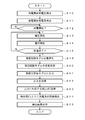
つぎに、第2実施形態の動作について図9に示すフローチャートを参照して説明する。なお、図9に示すフローチャートにおいて図7に示すフローチャートと対応する部分には同一の符号を付してその説明は省略する。図9に示すフローチャートでは、図7に示すフローチャートと比較するとステップS17~S26の処理が、ステップS40~S44に置換されている。これら以外の処理は、図7の場合と同様である。以下では、ステップS40~S44の処理を中心として説明する。
ステップS10~S16では、前述の場合と同様に、スタータモータ18が回転される際の電圧値と電流値が所定の間隔で測定され、RAM10cに格納される。そして、このRAM10cに格納された電圧値および電流値に基づいて等価回路モデルが最適化される。
ステップS40では、CPU10aは、等価回路モデルの定数を取得する。例えば、等価回路モデルを構成する素子の定数Rohm,Rct1,C1,Rct2,C2の少なくとも一部の定数が取得される。
ステップS41では、CPU10aは、ステップS40で取得した定数を、予め学習が施された教師付学習モデルに入力する。例えば、この教師付学習モデルとして、ニューラル・ネットワークが存在し、ステップS41の処理では、CPU10aは、ニューラル・ネットワークに対して、ステップS40で取得した素子の定数Rohm,Rct1,C1,Rct2,C2の少なくとも一部の定数が入力される。
ステップS42では、CPU10aは、教師付学習モデルの出力を取得する。例えば、アイドリングストップ専用鉛蓄電池の等価回路の定数が入力された場合、アイドリングストップ専用鉛蓄電池であることを示す情報が出力されるので、ステップS42では、この情報が取得される。
ステップS43では、CPU10aは、ステップS42で取得した出力に対応する検出式f()をROM10bから取得する。例えば、アイドリングストップ専用鉛蓄電池であることを示す情報が出力された場合には、このアイドリングストップ専用鉛蓄電池に対応する検出式f()がROM10bから取得される。
ステップS44では、CPU10aは、ステップS43で取得した検出式f()に基づいて、二次電池の状態を検出する。例えば、検出する状態としては、例えば、二次電池14の初期容量、劣化容量、放電残容量、所定の要求電流に対する応答電圧などがある。例えば、初期容量(SOH_ini)を例に上げると、前述した式(2)によって算出することができる。
ステップS23では、CPU10aは、ステップS44で求めた二次電池の状態を出力する。
以上の処理によれば、教師付学習モデルを用いて二次電池14の種類を識別し、識別結果に対応する検出式を用いて二次電池14の状態を検出するようにしたので、二次電池14の種類にかかわらず、正確に状態を検出することが可能になる。
(E)変形実施形態の説明
以上の実施形態は一例であって、本発明が上述したような場合のみに限定されるものでないことはいうまでもない。例えば、以上の第1実施形態では、定数Rtc1とC1の関係に基づいて二次電池14の種類を判定するようにしたが、これ以外の定数を用いて判定するようにしてもよい。また、2種類の定数を用いるのではなく、3つ以上の定数を用いて判定するようにしてもよい。また、式(1)に示す関数を用いて識別するようにしたが、例えば、2つの定数の比(例えば、RohmとRct1の比)を、所定の閾値と比較することで判定するようにしてもよい。より詳細には、Rohm/Rct1,Rct1/Rct2,Rct1/C1・・・等と、予め実験によって求めた閾値との比較によって識別するようにしてもよい。
以上の実施形態は一例であって、本発明が上述したような場合のみに限定されるものでないことはいうまでもない。例えば、以上の第1実施形態では、定数Rtc1とC1の関係に基づいて二次電池14の種類を判定するようにしたが、これ以外の定数を用いて判定するようにしてもよい。また、2種類の定数を用いるのではなく、3つ以上の定数を用いて判定するようにしてもよい。また、式(1)に示す関数を用いて識別するようにしたが、例えば、2つの定数の比(例えば、RohmとRct1の比)を、所定の閾値と比較することで判定するようにしてもよい。より詳細には、Rohm/Rct1,Rct1/Rct2,Rct1/C1・・・等と、予め実験によって求めた閾値との比較によって識別するようにしてもよい。
また、識別すべき二次電池の種類に応じて別の等価回路モデルの定数を用い、異なる計算式で識別指標を計算するようにしてもよい。また複数の等価回路モデルの定数を用いて識別指標を計算しても構わないし、識別方法として予め実験等によって求めた所定の閾値を超えるか否かで行ってもよい。
また、第1実施形態では、二次電池14の種類としてノーマル液式またはアイドリングストップ用の判別を行うようにしたが、これ以外の種類について判別するようにしてもよい。例えば、二次電池14の初期容量、製造メーカ、および、型番等を識別するようにしてもよい。
また、以上の各実施形態では、二次電池14の初期容量(SOH_ini)を求める場合を例に挙げて説明したが、これ以外にも、劣化容量、放電残容量、および、所定の要求電流に対する応答電圧を求めることも可能である。なお、これらを求めるための式としては、前述した式(2)と同様の式、または、等価回路モデルの素子の少なくとも一部を用いる関数を用いることができる。
また、第2実施形態では、ニューラル・ネットワークを用いて二次電池14の種類を識別するようにしたが、これ以外の教師付学習モデルを用いるようにしてもよい。例えば、サポート・ベクター・マシンを用いるようにしてもよい。サポート・ベクター・マシンにおいては図4の例であれば、教師データにおいて、分離曲線から教師データの各サンプル点までの距離の最小値が最大となるように(マージン最大化するように)分離曲線を決定することによって識別力の高い分離曲線を求めることができる。更に、場合によっては複数のモデル定数を用いた多元空間で同様に分離超平面・超曲面を求めることも出来る。すなわち、既知の種類の二次電池に対して等価回路モデルの定数を学習しておき、この既知のデータを教師データとして用いた教師付学習によって分離超平面・超曲面を求め、以後はこの分離超平面・超曲面を用いて識別する方法を用いるようにすればよい。
また、以上の各実施形態では、スタータモータ18を回転させる際の電圧と電流の変化に基づいて等価回路モデルを最適化するようにしたが、スタータモータ18以外の負荷に対して流れる電流に基づいて最適化行うようにしてもよい。例えば、放電回路15をスイッチング動作させ、そのときの二次電池14の電圧と電流を検出し、検出されたこれら電圧と電流に基づいて等価回路モデルを最適化するようにしてもよい。
また、以上の各実施形態では、等価回路モデルとしては図4に示すモデルを使用するようにしたが、これ以外の等価回路モデルを使用するようにしてもよい。例えば、並列接続された抵抗素子と容量素子が3段以上直列接続された等価回路モデルを使用するようにしてもよい。もちろん、これ以外の等価回路モデルを使用するようにしてもよい。
また、図7および図9に示すフローチャートは一例であって、これ以外の順序で処理を実行するようにしたり、あるいは、これ以外の処理を実行するようにしたりしてもよい。
また、以上の各実施形態では、二次電池14の状態検出のみを行うようにしたが、例えば、求めた状態に基づいて、例えば、エンジン17のアイドリングを停止する、いわゆる、アイドリングストップの実行を制御するようにしてもよい。具体的には、二次電池14のSOCが所定の閾値よりも高い場合には、アイドリングストップを実行し、所定の閾値よりも低いと判定された場合には、アイドリングストップを実行しないようにしてもよい。また、SOHが所定の閾値に近づいている場合には、例えば、負荷19の動作を停止させ、二次電池14のさらなる消耗を防ぐようにしてもよい。さらに、SOHが所定の閾値よりも小さい場合には、二次電池14を交換するように指示するメッセージを表示するようにしてもよい。
1 二次電池状態検出装置
10 制御部(最適化手段、識別手段、取得手段、検出手段)
10a CPU
10b ROM(格納手段)
10c RAM
10d 通信部
10e I/F
11 電圧センサ(測定手段)
12 電流センサ(測定手段)
13 温度センサ
14 二次電池
15 放電回路
16 オルタネータ
17 エンジン
18 スタータモータ
19 負荷
10 制御部(最適化手段、識別手段、取得手段、検出手段)
10a CPU
10b ROM(格納手段)
10c RAM
10d 通信部
10e I/F
11 電圧センサ(測定手段)
12 電流センサ(測定手段)
13 温度センサ
14 二次電池
15 放電回路
16 オルタネータ
17 エンジン
18 スタータモータ
19 負荷
Claims (10)
- 二次電池の状態を検出する二次電池状態検出装置において、
前記二次電池に流れる電流の電流値と、当該電流によって前記二次電池に生じる電圧の電圧値を所定の頻度で測定する測定手段と、
前記測定手段によって測定された電圧値および電流値に基づいて、前記二次電池の等価回路モデルの素子定数を最適化する最適化手段と、
前記最適化手段によって最適化された前記等価回路モデルの素子定数を参照して、前記二次電池の種類を識別する識別手段と、
前記等価回路モデルの素子定数に基づいて前記二次電池の状態を検出する検出式を、前記二次電池の種類毎に格納する格納手段と、
前記識別手段によって識別された種類に対応する検出式を、前記格納手段から取得する取得手段と、
前記取得手段によって取得された前記検出式に前記素子定数を適用することで、前記二次電池の状態を検出する検出手段と、
を有することを特徴とする二次電池状態検出装置。 - 前記識別手段は、前記等価回路モデルの複数の素子定数の相互の関係に基づいて、前記二次電池の種類を識別することを特徴とする請求項1に記載の二次電池状態検出装置。
- 前記識別手段は、前記等価回路モデルの複数の素子定数の比と、所定の閾値とを比較し、その大小関係に基づいて、前記二次電池の種類を識別することを特徴とする請求項2に記載の二次電池状態検出装置。
- 前記識別手段は、前記等価回路モデルの複数の素子定数から算出される識別指標値と、所定の閾値とを比較し、その大小関係に基づいて、前記二次電池の種類を識別することを特徴とする請求項2に記載の二次電池状態検出装置。
- 前記識別手段は、前記二次電池の等価回路モデルの定数を入力とし、当該二次電池の種類を特定するための情報を出力とする学習モデルであって、当該入出力のペアにより予め識別能力を持った学習モデルを有し、この学習モデルにより前記二次電池の種類を識別することを特徴とする請求項2に記載の二次電池状態検出装置。
- 前記学習モデルは、ニューラル・ネットワークまたはサポート・ベクター・マシンであることを特徴とする請求項5に記載の二次電池状態検出装置。
- 前記識別手段は、前記二次電池の種類として、鉛電池、ニッケル水素電池、リチウムイオン電池、および、ニッケル・カドミウム電池のいずれであるかを識別することを特徴とする請求項1乃至6のいずれか1項に記載の二次電池状態検出装置。
- 前記識別手段は、前記二次電池の種類として、鉛蓄電池の液式電池、シール式電池、および、アイドリングストップ用電池のいずれであるか、または、これらのいずれかの新品または中古品であることを識別することを特徴とする請求項1乃至6のいずれか1項に記載の二次電池状態検出装置。
- 前記検出手段は、前記二次電池の初期容量、劣化容量、放電残容量、および、所定の要求電流に対する応答電圧のうちの少なくとも一つを検出することを特徴とする請求項1乃至8のいずれか1項に記載の二次電池状態検出装置。
- 二次電池の状態を検出する二次電池状態検出方法において、
前記二次電池に流れる電流の電流値と、当該電流によって前記二次電池に生じる電圧の電圧値を所定の頻度で測定する測定ステップと、
前記測定ステップにおいて測定された電圧値および電流値に基づいて、前記二次電池の等価回路モデルの素子定数を最適化する最適化ステップと、
前記最適化ステップにおいて最適化された前記等価回路モデルの素子定数を参照して、前記二次電池の種類を識別する識別ステップと、
前記等価回路モデルの素子定数に基づいて前記二次電池の状態を検出する検出式を、前記二次電池の種類毎に格納されている格納手段から取得する取得ステップと、
前記取得ステップにおいて取得された前記検出式に前記素子定数を適用することで、前記二次電池の状態を検出する検出ステップと、
を有することを特徴とする二次電池状態検出方法。
Priority Applications (3)
| Application Number | Priority Date | Filing Date | Title |
|---|---|---|---|
| EP14762948.9A EP2955533B1 (en) | 2013-03-14 | 2014-02-12 | Secondary cell state detection device and method for detecting secondary cell state |
| CN201480013224.4A CN105026945B (zh) | 2013-03-14 | 2014-02-12 | 二次电池状态检测装置及二次电池状态检测方法 |
| US14/852,329 US10466302B2 (en) | 2013-03-14 | 2015-09-11 | Secondary battery state detecting device and secondary battery state detecting method |
Applications Claiming Priority (2)
| Application Number | Priority Date | Filing Date | Title |
|---|---|---|---|
| JP2013052571A JP5810116B2 (ja) | 2013-03-14 | 2013-03-14 | 二次電池状態検出装置および二次電池状態検出方法 |
| JP2013-052571 | 2013-03-14 |
Related Child Applications (1)
| Application Number | Title | Priority Date | Filing Date |
|---|---|---|---|
| US14/852,329 Continuation US10466302B2 (en) | 2013-03-14 | 2015-09-11 | Secondary battery state detecting device and secondary battery state detecting method |
Publications (1)
| Publication Number | Publication Date |
|---|---|
| WO2014141796A1 true WO2014141796A1 (ja) | 2014-09-18 |
Family
ID=51536472
Family Applications (1)
| Application Number | Title | Priority Date | Filing Date |
|---|---|---|---|
| PCT/JP2014/053135 Ceased WO2014141796A1 (ja) | 2013-03-14 | 2014-02-12 | 二次電池状態検出装置および二次電池状態検出方法 |
Country Status (5)
| Country | Link |
|---|---|
| US (1) | US10466302B2 (ja) |
| EP (1) | EP2955533B1 (ja) |
| JP (1) | JP5810116B2 (ja) |
| CN (1) | CN105026945B (ja) |
| WO (1) | WO2014141796A1 (ja) |
Cited By (3)
| Publication number | Priority date | Publication date | Assignee | Title |
|---|---|---|---|---|
| JP2019023995A (ja) * | 2017-05-03 | 2019-02-14 | 株式会社半導体エネルギー研究所 | 蓄電装置、半導体装置、icチップ、電子機器 |
| CN116774077A (zh) * | 2023-06-21 | 2023-09-19 | 广东电网有限责任公司 | 储能电站电池的健康检测方法、装置、设备及存储介质 |
| EP4521130A4 (en) * | 2023-03-08 | 2026-03-04 | Toyo System Co Ltd | Diagnosis device for on-vehicle secondary battery |
Families Citing this family (38)
| Publication number | Priority date | Publication date | Assignee | Title |
|---|---|---|---|---|
| JP5798067B2 (ja) * | 2012-03-13 | 2015-10-21 | プライムアースEvエナジー株式会社 | 二次電池の状態推定装置 |
| JP6479650B2 (ja) * | 2013-03-07 | 2019-03-06 | 古河電気工業株式会社 | 二次電池状態検出装置および二次電池状態検出方法 |
| JP6555773B2 (ja) * | 2014-11-18 | 2019-08-07 | 学校法人立命館 | 蓄電残量推定装置、蓄電池の蓄電残量を推定する方法、及びコンピュータプログラム |
| JP6490414B2 (ja) * | 2014-12-05 | 2019-03-27 | 古河電気工業株式会社 | 二次電池状態検出装置および二次電池状態検出方法 |
| US10145899B2 (en) * | 2015-02-12 | 2018-12-04 | Panasonic Intellectual Property Management Co., Ltd. | Battery class determination device and battery class determination method |
| JP6702672B2 (ja) * | 2015-09-03 | 2020-06-03 | キヤノン株式会社 | インプリント装置、物品の製造方法及び供給装置 |
| JP6606996B2 (ja) | 2015-11-24 | 2019-11-20 | 株式会社Gsユアサ | 電池システム、二次電池の電池監視装置および二次電池の監視方法 |
| KR101772036B1 (ko) * | 2015-12-30 | 2017-08-28 | 주식회사 효성 | 배터리 수명 추정 방법 및 장치 |
| JP6898479B2 (ja) * | 2016-02-05 | 2021-07-07 | ファナック株式会社 | 操作メニューの表示を学習する機械学習器,数値制御装置,工作機械システム,製造システムおよび機械学習方法 |
| JP2017138881A (ja) | 2016-02-05 | 2017-08-10 | ファナック株式会社 | 操作メニューの表示を学習する機械学習器,数値制御装置,工作機械システム,製造システムおよび機械学習方法 |
| US10436845B2 (en) * | 2016-03-01 | 2019-10-08 | Faraday & Future Inc. | Electric vehicle battery monitoring system |
| JP6615011B2 (ja) | 2016-03-09 | 2019-12-04 | 日立オートモティブシステムズ株式会社 | 電池管理システム、電池システムおよびハイブリッド車両制御システム |
| DE102016206538A1 (de) * | 2016-04-19 | 2017-10-19 | Audi Ag | Verfahren zum Bestimmen eines Ladezustands einer Batterie für ein Kraftfahrzeug, Vorrichtung sowie Kraftfahrzeug |
| CN107340476B (zh) * | 2016-04-29 | 2021-01-26 | 株式会社日立制作所 | 电池的电气状态监测系统和电气状态监测方法 |
| US10656215B2 (en) | 2016-11-07 | 2020-05-19 | Nissan Motor Co., Ltd. | Short circuit detection device |
| KR102035679B1 (ko) * | 2016-11-29 | 2019-10-23 | 주식회사 엘지화학 | 배터리 노화상태 산출 방법 및 시스템 |
| JP6895786B2 (ja) * | 2017-03-29 | 2021-06-30 | 古河電気工業株式会社 | 二次電池状態検出装置および二次電池状態検出方法 |
| JP6904176B2 (ja) * | 2017-09-01 | 2021-07-14 | トヨタ自動車株式会社 | 二次電池の再利用方法および二次電池システム |
| JP2019158831A (ja) * | 2018-03-16 | 2019-09-19 | 株式会社Gsユアサ | 検査方法、検査装置及び学習モデル |
| WO2019181727A1 (ja) * | 2018-03-20 | 2019-09-26 | 株式会社Gsユアサ | 異常要因判定装置、劣化判定装置、コンピュータプログラム、劣化判定方法及び異常要因判定方法 |
| JP7072414B2 (ja) * | 2018-03-20 | 2022-05-20 | 古河電気工業株式会社 | 充電可能電池状態検出装置および充電可能電池状態検出方法 |
| US11413802B2 (en) | 2018-03-22 | 2022-08-16 | Honda Motor Co., Ltd. | Reusable mold for injection molding and molding method |
| CA3095272C (en) * | 2018-03-28 | 2021-11-30 | Toyo System Co., Ltd. | Degradation state determination device and degradation state determination method |
| JP7145035B2 (ja) | 2018-10-29 | 2022-09-30 | 本田技研工業株式会社 | 学習装置、学習方法、及びプログラム |
| KR102768452B1 (ko) * | 2019-04-05 | 2025-02-13 | 주식회사 엘지에너지솔루션 | 배터리 관리 장치 및 방법 |
| CN109900937B (zh) * | 2019-04-10 | 2020-12-08 | 河南科技大学 | 一种具有温度补偿功能的锂电池电荷状态估算方法 |
| US11472083B2 (en) | 2019-09-25 | 2022-10-18 | Honda Motor Co., Ltd. | Injection mold master unit die back plate cooling with metal backfilled plastic mold |
| JP6944208B2 (ja) * | 2020-01-20 | 2021-10-06 | 東洋システム株式会社 | 充電器 |
| EP3885776B1 (en) * | 2020-03-24 | 2024-01-17 | Siemens Aktiengesellschaft | Method, computer-implemented tool and battery management system for estimating states of health of batteries storing electrical energy and battery energy storage system |
| JP6997473B2 (ja) * | 2020-04-13 | 2022-02-04 | 東洋システム株式会社 | 二次電池検査方法および二次電池検査装置 |
| JP7448201B2 (ja) * | 2020-05-21 | 2024-03-12 | アクソンデータマシン株式会社 | 人工知能技術を用いた2次電池の状態推定装置 |
| TWI741632B (zh) * | 2020-06-03 | 2021-10-01 | 龍華科技大學 | 電池智能分流模組之電阻溫度係數預測方法、電流量測補償校正方法及其裝置 |
| CN111856299A (zh) * | 2020-07-29 | 2020-10-30 | 中国联合网络通信集团有限公司 | 电源状态的确定方法、装置及设备 |
| CN112230153B (zh) * | 2020-10-13 | 2021-07-20 | 东华大学 | 测量电池阻抗值的方法和装置 |
| JP2022139501A (ja) * | 2021-03-12 | 2022-09-26 | 株式会社豊田中央研究所 | 劣化判定装置、劣化判定システム、劣化判定方法及びそのプログラム |
| WO2023190695A1 (ja) | 2022-03-31 | 2023-10-05 | 古河電気工業株式会社 | バッテリ制御監視システム、バッテリ制御監視装置、バッテリ制御監視方法、バッテリ制御監視プログラム、および記憶媒体 |
| DE102022112886A1 (de) | 2022-05-23 | 2023-11-23 | Volkswagen Aktiengesellschaft | Verfahren zum Prognostizieren eines Batteriezustands einer Batterie eines Kraftfahrzeugs, ein Batteriesystem und ein Kraftfahrzeug |
| CN116929437B (zh) * | 2023-09-15 | 2023-12-08 | 深圳和润达科技有限公司 | 应用于电芯化成分容系统的传感器信息识别方法及装置 |
Citations (6)
| Publication number | Priority date | Publication date | Assignee | Title |
|---|---|---|---|---|
| JPH03183328A (ja) * | 1989-12-11 | 1991-08-09 | Canon Inc | 電池残量演算装置 |
| JPH09166652A (ja) * | 1995-12-15 | 1997-06-24 | Mk Seiko Co Ltd | バッテリー診断方法およびそれを用いたバッテリー診断装置 |
| JP2005221487A (ja) | 2004-02-09 | 2005-08-18 | Furukawa Electric Co Ltd:The | 二次電池の内部インピーダンス測定方法、二次電池の内部インピーダンス測定装置、二次電池劣化判定装置及び電源システム |
| JP2007187534A (ja) | 2006-01-12 | 2007-07-26 | Furukawa Electric Co Ltd:The | バッテリ放電能力判定方法、バッテリ放電能力判定装置、及び電源システム |
| JP2009244180A (ja) | 2008-03-31 | 2009-10-22 | Furukawa Electric Co Ltd:The | バッテリ状態検知方法及びバッテリ状態検知装置 |
| JP2012132724A (ja) * | 2010-12-20 | 2012-07-12 | Furukawa Electric Co Ltd:The | 満充電検知装置および満充電検知方法 |
Family Cites Families (8)
| Publication number | Priority date | Publication date | Assignee | Title |
|---|---|---|---|---|
| JP2000023374A (ja) * | 1998-06-30 | 2000-01-21 | Fuji Photo Film Co Ltd | 二次電池の識別装置および方法 |
| US8560124B2 (en) * | 2007-07-13 | 2013-10-15 | Cummins Inc. | Idle control system and method for adaptive temperature control |
| WO2010056303A1 (en) * | 2008-11-12 | 2010-05-20 | Bravo Zulu International Ltd. | Lead acid battery de-sulfation |
| WO2010063001A1 (en) * | 2008-11-26 | 2010-06-03 | Wireless Environment, Llc | Wireless lighting devices and applications |
| JP4744622B2 (ja) * | 2009-07-01 | 2011-08-10 | トヨタ自動車株式会社 | 車両の制御装置 |
| JP5493657B2 (ja) * | 2009-09-30 | 2014-05-14 | 新神戸電機株式会社 | 蓄電池装置並びに蓄電池の電池状態評価装置及び方法 |
| JP4689756B1 (ja) * | 2010-03-31 | 2011-05-25 | 古河電気工業株式会社 | 電池内部状態推定装置および電池内部状態推定方法 |
| US10664562B2 (en) * | 2013-02-24 | 2020-05-26 | Fairchild Semiconductor Corporation and University of Connecticut | Battery state of charge tracking, equivalent circuit selection and benchmarking |
-
2013
- 2013-03-14 JP JP2013052571A patent/JP5810116B2/ja active Active
-
2014
- 2014-02-12 WO PCT/JP2014/053135 patent/WO2014141796A1/ja not_active Ceased
- 2014-02-12 CN CN201480013224.4A patent/CN105026945B/zh active Active
- 2014-02-12 EP EP14762948.9A patent/EP2955533B1/en active Active
-
2015
- 2015-09-11 US US14/852,329 patent/US10466302B2/en active Active
Patent Citations (7)
| Publication number | Priority date | Publication date | Assignee | Title |
|---|---|---|---|---|
| JPH03183328A (ja) * | 1989-12-11 | 1991-08-09 | Canon Inc | 電池残量演算装置 |
| JPH09166652A (ja) * | 1995-12-15 | 1997-06-24 | Mk Seiko Co Ltd | バッテリー診断方法およびそれを用いたバッテリー診断装置 |
| JP2005221487A (ja) | 2004-02-09 | 2005-08-18 | Furukawa Electric Co Ltd:The | 二次電池の内部インピーダンス測定方法、二次電池の内部インピーダンス測定装置、二次電池劣化判定装置及び電源システム |
| JP2007187534A (ja) | 2006-01-12 | 2007-07-26 | Furukawa Electric Co Ltd:The | バッテリ放電能力判定方法、バッテリ放電能力判定装置、及び電源システム |
| JP4532416B2 (ja) | 2006-01-12 | 2010-08-25 | 古河電気工業株式会社 | バッテリ放電能力判定方法、バッテリ放電能力判定装置、及び電源システム |
| JP2009244180A (ja) | 2008-03-31 | 2009-10-22 | Furukawa Electric Co Ltd:The | バッテリ状態検知方法及びバッテリ状態検知装置 |
| JP2012132724A (ja) * | 2010-12-20 | 2012-07-12 | Furukawa Electric Co Ltd:The | 満充電検知装置および満充電検知方法 |
Non-Patent Citations (1)
| Title |
|---|
| See also references of EP2955533A4 |
Cited By (5)
| Publication number | Priority date | Publication date | Assignee | Title |
|---|---|---|---|---|
| JP2019023995A (ja) * | 2017-05-03 | 2019-02-14 | 株式会社半導体エネルギー研究所 | 蓄電装置、半導体装置、icチップ、電子機器 |
| US11594770B2 (en) | 2017-05-03 | 2023-02-28 | Semiconductor Energy Laboratory Co., Ltd. | Neural network, power storage system, vehicle, and electronic device |
| US11955612B2 (en) | 2017-05-03 | 2024-04-09 | Semiconductor Energy Laboratory Co., Ltd. | Neural network, power storage system, vehicle, and electronic device |
| EP4521130A4 (en) * | 2023-03-08 | 2026-03-04 | Toyo System Co Ltd | Diagnosis device for on-vehicle secondary battery |
| CN116774077A (zh) * | 2023-06-21 | 2023-09-19 | 广东电网有限责任公司 | 储能电站电池的健康检测方法、装置、设备及存储介质 |
Also Published As
| Publication number | Publication date |
|---|---|
| EP2955533B1 (en) | 2017-05-17 |
| US20160003912A1 (en) | 2016-01-07 |
| JP5810116B2 (ja) | 2015-11-11 |
| US10466302B2 (en) | 2019-11-05 |
| CN105026945A (zh) | 2015-11-04 |
| JP2014178213A (ja) | 2014-09-25 |
| CN105026945B (zh) | 2017-12-05 |
| EP2955533A4 (en) | 2016-06-15 |
| EP2955533A1 (en) | 2015-12-16 |
Similar Documents
| Publication | Publication Date | Title |
|---|---|---|
| JP5810116B2 (ja) | 二次電池状態検出装置および二次電池状態検出方法 | |
| US11163010B2 (en) | Secondary battery deterioration estimation device and secondary battery deterioration estimation method | |
| JP6479650B2 (ja) | 二次電池状態検出装置および二次電池状態検出方法 | |
| US11143710B2 (en) | Device for estimating degradation of secondary cell, and method for estimating degradation of secondary cell | |
| US9134381B2 (en) | Predicting state of a battery | |
| US10436847B2 (en) | Secondary battery state detection device and secondary battery state detection method | |
| JP4645382B2 (ja) | バッテリ状態検知装置、バッテリ状態検知方法 | |
| JP6277864B2 (ja) | 電池内部状態推定装置 | |
| EP3551494B1 (en) | A method of estimating a charge state for a battery cell | |
| US10393814B2 (en) | Secondary battery state detection device and secondary battery state detection method | |
| KR20160000317A (ko) | 배터리의 상태 정보를 학습 및 추정하는 장치 및 방법 | |
| JP6575308B2 (ja) | 内部抵抗算出装置、コンピュータプログラム及び内部抵抗算出方法 | |
| JP5653881B2 (ja) | 二次電池状態検出装置および二次電池状態検出方法 | |
| CN114690057A (zh) | 一种电池系统性能评估的方法和系统 | |
| US20230324463A1 (en) | Method and Apparatus for Operating a System for Detecting an Anomaly of an Electrical Energy Store for a Device by Means of Machine Learning Methods | |
| JP6498920B2 (ja) | 二次電池状態検出装置および二次電池状態検出方法 | |
| US20160109527A1 (en) | Method and apparatus for determining a change in resistance of an energy storage device and vehicle |
Legal Events
| Date | Code | Title | Description |
|---|---|---|---|
| WWE | Wipo information: entry into national phase |
Ref document number: 201480013224.4 Country of ref document: CN |
|
| 121 | Ep: the epo has been informed by wipo that ep was designated in this application |
Ref document number: 14762948 Country of ref document: EP Kind code of ref document: A1 |
|
| REEP | Request for entry into the european phase |
Ref document number: 2014762948 Country of ref document: EP |
|
| WWE | Wipo information: entry into national phase |
Ref document number: 2014762948 Country of ref document: EP |
|
| NENP | Non-entry into the national phase |
Ref country code: DE |