WO2014141885A1 - Tambour de moulage - Google Patents
Tambour de moulage Download PDFInfo
- Publication number
- WO2014141885A1 WO2014141885A1 PCT/JP2014/054769 JP2014054769W WO2014141885A1 WO 2014141885 A1 WO2014141885 A1 WO 2014141885A1 JP 2014054769 W JP2014054769 W JP 2014054769W WO 2014141885 A1 WO2014141885 A1 WO 2014141885A1
- Authority
- WO
- WIPO (PCT)
- Prior art keywords
- drum
- fixing member
- shaft
- molding
- slider
- Prior art date
- Legal status (The legal status is an assumption and is not a legal conclusion. Google has not performed a legal analysis and makes no representation as to the accuracy of the status listed.)
- Ceased
Links
Images


Classifications
-
- B—PERFORMING OPERATIONS; TRANSPORTING
- B29—WORKING OF PLASTICS; WORKING OF SUBSTANCES IN A PLASTIC STATE IN GENERAL
- B29D—PRODUCING PARTICULAR ARTICLES FROM PLASTICS OR FROM SUBSTANCES IN A PLASTIC STATE
- B29D30/00—Producing pneumatic or solid tyres or parts thereof
- B29D30/06—Pneumatic tyres or parts thereof (e.g. produced by casting, moulding, compression moulding, injection moulding, centrifugal casting)
- B29D30/08—Building tyres
- B29D30/20—Building tyres by the flat-tyre method, i.e. building on cylindrical drums
-
- B—PERFORMING OPERATIONS; TRANSPORTING
- B29—WORKING OF PLASTICS; WORKING OF SUBSTANCES IN A PLASTIC STATE IN GENERAL
- B29D—PRODUCING PARTICULAR ARTICLES FROM PLASTICS OR FROM SUBSTANCES IN A PLASTIC STATE
- B29D30/00—Producing pneumatic or solid tyres or parts thereof
- B29D30/06—Pneumatic tyres or parts thereof (e.g. produced by casting, moulding, compression moulding, injection moulding, centrifugal casting)
- B29D30/08—Building tyres
- B29D30/20—Building tyres by the flat-tyre method, i.e. building on cylindrical drums
- B29D30/24—Drums
- B29D30/26—Accessories or details, e.g. membranes, transfer rings
-
- B—PERFORMING OPERATIONS; TRANSPORTING
- B29—WORKING OF PLASTICS; WORKING OF SUBSTANCES IN A PLASTIC STATE IN GENERAL
- B29D—PRODUCING PARTICULAR ARTICLES FROM PLASTICS OR FROM SUBSTANCES IN A PLASTIC STATE
- B29D30/00—Producing pneumatic or solid tyres or parts thereof
- B29D30/06—Pneumatic tyres or parts thereof (e.g. produced by casting, moulding, compression moulding, injection moulding, centrifugal casting)
- B29D30/08—Building tyres
- B29D30/20—Building tyres by the flat-tyre method, i.e. building on cylindrical drums
- B29D30/24—Drums
- B29D30/242—Drums for manufacturing substantially cylindrical tyre components without cores or beads, e.g. treads or belts
-
- B—PERFORMING OPERATIONS; TRANSPORTING
- B29—WORKING OF PLASTICS; WORKING OF SUBSTANCES IN A PLASTIC STATE IN GENERAL
- B29D—PRODUCING PARTICULAR ARTICLES FROM PLASTICS OR FROM SUBSTANCES IN A PLASTIC STATE
- B29D30/00—Producing pneumatic or solid tyres or parts thereof
- B29D30/06—Pneumatic tyres or parts thereof (e.g. produced by casting, moulding, compression moulding, injection moulding, centrifugal casting)
- B29D30/08—Building tyres
- B29D30/20—Building tyres by the flat-tyre method, i.e. building on cylindrical drums
- B29D30/24—Drums
- B29D30/244—Drums for manufacturing substantially cylindrical tyre components with cores or beads, e.g. carcasses
- B29D30/245—Drums for the single stage building process, i.e. the building-up of the cylindrical carcass and the toroidal expansion of it are realised on the same drum
-
- B—PERFORMING OPERATIONS; TRANSPORTING
- B29—WORKING OF PLASTICS; WORKING OF SUBSTANCES IN A PLASTIC STATE IN GENERAL
- B29D—PRODUCING PARTICULAR ARTICLES FROM PLASTICS OR FROM SUBSTANCES IN A PLASTIC STATE
- B29D30/00—Producing pneumatic or solid tyres or parts thereof
- B29D30/06—Pneumatic tyres or parts thereof (e.g. produced by casting, moulding, compression moulding, injection moulding, centrifugal casting)
- B29D30/08—Building tyres
- B29D30/20—Building tyres by the flat-tyre method, i.e. building on cylindrical drums
- B29D30/24—Drums
- B29D30/26—Accessories or details, e.g. membranes, transfer rings
- B29D2030/2642—Adjusting the diameter of the drum, to match its circumference with the length of ply
-
- B—PERFORMING OPERATIONS; TRANSPORTING
- B29—WORKING OF PLASTICS; WORKING OF SUBSTANCES IN A PLASTIC STATE IN GENERAL
- B29D—PRODUCING PARTICULAR ARTICLES FROM PLASTICS OR FROM SUBSTANCES IN A PLASTIC STATE
- B29D30/00—Producing pneumatic or solid tyres or parts thereof
- B29D30/06—Pneumatic tyres or parts thereof (e.g. produced by casting, moulding, compression moulding, injection moulding, centrifugal casting)
- B29D30/08—Building tyres
- B29D30/20—Building tyres by the flat-tyre method, i.e. building on cylindrical drums
- B29D30/24—Drums
- B29D30/26—Accessories or details, e.g. membranes, transfer rings
- B29D2030/2657—Radially expandable and contractable drum comprising a set of circumferentially arranged rigid elements, e.g. fingers or arms
Definitions
- the present invention relates to a molding drum that expands and contracts, for example, a tire molding drum, and more particularly to a molding drum that can set an expansion / contraction stroke longer than that of a conventional molding drum.
- a molding drum for example, a tire molding drum (hereinafter simply referred to as a drum), it is composed of a plurality of segments obtained by dividing the peripheral surface, and each segment has a distal end of a plurality of extendable arms extending radially from the central axis of the drum. It is known that a tire constituent member is molded so that no gap is generated between segments when the arm is extended. When this drum is used, there is no problem as long as the inner diameter of the tire to be molded is a size that does not cause a gap between the segments. If there is a gap between the segments, a defect such as a defect in the uniformity of the product tire or a tire component wound around the drum falls into the gap. Therefore, it is impossible to mold a plurality of types of tire constituent members having different tire sizes (inner diameters) with one drum.
- the first and second segments having different circumferential lengths are provided, and the drum surface having the first diameter formed by the first segment and the second segment are formed.
- a drum that can be used for molding two tire components having different inner diameters by selecting two drum diameters of the drum surface having the second diameter see Patent Document 1). .
- Patent Document 1 the configuration of the drum disclosed in Patent Document 1 can be applied only to the molding of tires having two different inner diameters, so that the effect is limited.
- the present invention has been made in view of the above-mentioned problems in conventional drums.
- the purpose of the present invention is to avoid the formation of a gap between adjacent segments even if the radial length of the swinging arm is increased, and the perfect circle of the drum. It is to be able to cope with multi-size tires while maintaining the degree.
- the invention of claim 1 is an expandable / contractable molding drum having a plurality of segments constituting a circumferential surface, wherein one end portion is on the outer peripheral surface of a cylindrical slider that is externally fitted to the drum shaft, and the other end portion is
- the segment has a plurality of swing arms each swingably attached to the segment, and includes a plurality of segment expansion / contraction mechanisms formed by the plurality of swing arms at intervals along the drum shaft.
- the molding drum expands / contracts by the plurality of segment expansion / contraction mechanisms as the drum moves in the axial direction.
- the molding drum according to the first aspect wherein a fixing member attached to the drum shaft, and the other end portion of the swing arm on the fixing member has a diameter of the drum shaft. And a plurality of guide members for guiding in a direction.
- the guide member is a molding drum which is disposed at an interval in the drum axial direction with respect to the fixed member.
- the fixing member is attached to the first fixing member and the first fixing member, and is in an axial direction with respect to the first fixing member.
- the first fixing member is configured to guide the other end of the swing arm of the one segment expansion / contraction mechanism adjacent to each other along the drum axis.
- the fixing member is a molding drum that guides the other end of the swing arm of the other segment expansion / contraction mechanism.
- the slider is connected to a reciprocating middle shaft disposed in the drum shaft through a slit of the drum shaft. It is a molding drum.
- a plurality of segment expansion / contraction mechanisms constituted by the plurality of swing arms are provided at intervals along the drum axis, and the plurality of segments are accompanied by movement of the slider in the drum axis direction. Since expansion / contraction is performed by the expansion / contraction mechanism, a plurality of rows of swing arms can be expanded / contracted with respect to one slider. As a result, even if the radial length of the swing arm is increased, there is no gap between adjacent segments, and it is possible to deal with multi-size tires while maintaining the roundness of the drum.
- the fixing member attached to the drum shaft since it has a plurality of guide members for guiding the other end portion of the swing arm in the radial direction of the drum shaft,
- the swing arm can be expanded and contracted smoothly, and the length in the drum axis direction can be shortened as compared with, for example, a link mechanism provided at the other end of the swing arm, and the apparatus can be made compact.
- the said guide member since the said guide member is arrange
- the fixing member includes first and second fixing members, and adjacent end portions of the plurality of swing arms are first and second in the slider outer peripheral direction, respectively. Therefore, the swing arm can be expanded and contracted with high accuracy, and the size of the entire drum can be made compact. In addition, it is possible to expand and contract many swing arms with simple equipment. According to invention of Claim 5, since the axis
- FIG. 4 is an enlarged view of a main part of the drum shown in FIG. 3.
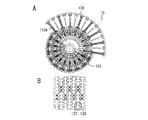
- FIG. 5A is a side view of the drum of FIG. 4 as viewed from the right side of the drawing, in which the upper part on the right side shows a state where the swing arm is expanded, and the lower part on the left side shows a state where the drum is contracted.
- FIG. 5B is a diagram showing the surface of the drum showing a state in which the comb teeth of the segments are engaged most deeply when the swing arm is contracted.
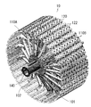
- FIG. 1 is a diagram schematically illustrating a tire molding apparatus including a drum according to an embodiment of the present invention.
- the tire molding apparatus is arranged concentrically within a drum 10, a rotating mechanism 20 that rotates the drum 10, and a rotating shaft (hereinafter referred to as a drum shaft) 101 of the drum 10.
- the center shaft driving mechanism 30 that reciprocates a center shaft 105 (FIG. 3), which will be described later, and a support portion 40 that supports the whole on the floor G are included.
- the rotation mechanism 20 is arbitrary as long as the drum 10 can be rotationally driven, and is a known mechanism such as a mechanism for transmitting the rotation of the drive motor to the drum shaft 101.
- the middle shaft drive mechanism 30 may use a known linear motion mechanism such as a cylinder mechanism or a screw transmission mechanism.
- the drum 10 includes a plurality of swing arms 110A that are alternately arranged at equal intervals around the drum shaft 101 and alternately in two front and rear rows along the drum shaft 101. 110B and a segment 120 attached to the tip of each swing arm 110A, 110B.
- Each segment 120 has an arcuate upper surface so that the entire segment 120 forms a circumferential surface, and comb-shaped irregularities (hereinafter referred to as comb teeth) 122 are formed at both ends of the drum circumferential direction.
- the comb teeth 122 of the adjacent segments 120 mesh with each other to form a continuous circumferential surface.
- the swing arms 110A and 110B swing at equal intervals to the slider along the circumference of the outer peripheral surface of a cylindrical slider that is fitted around the drum shaft 101, and at the other end to the segment. It is mounted movably.
- the plurality of swing arms 110A and 110B constitute independent segment expansion / contraction mechanisms, and the respective segment expansion / contraction mechanisms are arranged at intervals along the drum shaft 101 as shown in the figure.
- each segment 120 is brought into a state where the comb teeth 122 of the adjacent segments 120 are engaged with each other. While maintaining, it moves in the radial direction between the radially inner reduced position and the radially outer expanded position.
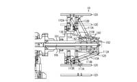
- FIG. 3 is a cross-sectional view of the drum for explaining the expansion / contraction mechanism of the drum 10.
- the upper side of FIG. 3 shows a state in which the diameter of the drum 10 is increased, and the lower side shows a state in which the diameter has been reduced.
- the drum shaft 101 is configured as a hollow tube as shown in the figure, and an intermediate shaft 105 is mounted in the hollow portion so as to be reciprocally movable by the intermediate shaft drive mechanism 30 (FIG. 1).
- the slider 140 has a cylindrical shape and is externally fitted to the drum shaft 101, and connecting portions 142 projecting inward from the inside thereof (for example, at intervals of 180 ° or 90 ° intervals along the inner periphery of the slider 140. And the number thereof is arbitrary).
- the connecting portion 142 is clamped (fixed) from both sides so as to penetrate the guide groove 102 formed along the drum shaft 101 and sandwich the large-diameter portion or the convex portion 105a of the middle shaft 105.
- FIG. 4 is an enlarged view of a main part of the drum 10 shown in FIG.
- One end portions of the swing arms 110A and 110B constituting different segment expansion / contraction mechanisms are spaced in the drum axis direction of the slider 140, and are equally spaced along the circumference and phase (angle) with respect to each other around the drum axis.
- annular body 130 that is a first fixing member serving as a fixing member is inserted into the center hole of the annular body 130 and the drum shaft 101 is inserted.
- the shaft 101 is screwed and attached integrally.
- a plurality of guide members 132 ⁇ / b> A extending in the radial direction are attached to the outer surface in the radial direction of the annular body 130 at equal intervals (equal angular intervals) with screws or the like.
- an auxiliary annular body 134 as a second fixing member having an L-shaped cross section is attached to the inner surface in the radial direction of the guide rail 132A of the annular body 130 with, for example, a screw.
- a plurality of guide rails 132B extending in the radial direction along the outer periphery thereof are attached at equal intervals (equal angular intervals) with screws or the like.
- the guide rails 132A and 132B are arranged at the same distance from the axis of the drum shaft 101.
- the L-shaped brackets 114A and 114B connected to the back surfaces of the segments 120 of the swing arms 110A and 110B by screws or the like are slidably engaged with the guide rails 132A and 132B, respectively.
- the radially outer ends (other ends) of the swing arms 110A and 110B are pivotally attached by pins 113A and 113B, respectively. Has been.
- FIG. 5A is a side view of the drum 10 of FIG. 4 as viewed from the right side in the figure.
- the upper part on the right side is a state where the swinging arms 110A and 110B are expanded, and the lower part on the left side is contracted.
- FIG. 5B is a diagram illustrating the surface of the drum 10 in a state where the comb teeth 122 of the segment 120 are engaged with each other when the swing arms 110A and 110B are contracted. In this state, the comb teeth 122 of the adjacent segments 120 are closely meshed with each other.
- the state of the comb teeth 122 of the segment 120 when the swing arms 110A and 110B are expanded is, for example, as shown in FIG. There is no gap.
- FIG. 4 shows the positions of the slider 140 and the swing arms 110A and 110B in a state where the diameter of the drum is expanded.
- adjacent ends of the swing arms 110A and 110B arranged in a line in a plane perpendicular to the direction of the drum shaft 101 along the circumference of the slider 140 are connected to each other.
- the segments 120 are alternately arranged in the front and rear rows along the direction of the drum shaft 101, and the segments 120 with the comb teeth 122 are provided at the respective leading ends (the other ends) in the radial direction.
- the segments 120 can be attached at twice the density. Therefore, the roundness when each segment 120 is expanded is improved as compared with the conventional case.
- the tire size range that can be molded can be made wider than that of the conventional drum described in Patent Document 1.
- the adjacent end portions of the one end portion of the swing arm are respectively attached to the slider so as to be swingable alternately at one of two positions spaced in the drum axis direction of the slider.
- the balance of the drum itself is stable, and it is possible to handle the molding of multiple sizes with small equipment.
- the guide member is disposed at a distance in the drum axis direction with respect to the fixed member, the expansion and contraction of the swing arm securely attached to one slider with a small number of parts and simple equipment. The effect that it is possible is also obtained.
- the swing arm has been described as having a configuration in which the swing arm is arranged in two rows in the longitudinal direction of the slider (in the drum axis direction), but is not necessarily limited thereto.
- a three-row arrangement may be used, and if the number of rows is increased, the structure becomes complicated and restrictions are imposed.
- the number of rows is increased, the number of segments can be increased accordingly, and the roundness of the drum is further improved. Therefore, the expansion / contraction stroke of the drum by the swing arm can be further increased.
- the swing arm expansion / contraction mechanism includes the fixed member (annular body 130) and the guide members (guide rails 132A and 132B), but the present invention is not limited to this.
- a well-known link mechanism for expanding and contracting the swing arm can be used.
Landscapes
- Engineering & Computer Science (AREA)
- Mechanical Engineering (AREA)
- Manufacturing & Machinery (AREA)
- Tyre Moulding (AREA)
Abstract
Priority Applications (4)
| Application Number | Priority Date | Filing Date | Title |
|---|---|---|---|
| EP14763014.9A EP2974853B1 (fr) | 2013-03-12 | 2014-02-26 | Tambour de moulage |
| RU2015143205A RU2625238C2 (ru) | 2013-03-12 | 2014-02-26 | Формовочный барабан |
| CN201480014351.6A CN105073396B (zh) | 2013-03-12 | 2014-02-26 | 成型鼓 |
| US14/771,641 US10279555B2 (en) | 2013-03-12 | 2014-02-26 | Molding drum |
Applications Claiming Priority (2)
| Application Number | Priority Date | Filing Date | Title |
|---|---|---|---|
| JP2013-049496 | 2013-03-12 | ||
| JP2013049496A JP5579295B1 (ja) | 2013-03-12 | 2013-03-12 | 成型ドラム |
Publications (1)
| Publication Number | Publication Date |
|---|---|
| WO2014141885A1 true WO2014141885A1 (fr) | 2014-09-18 |
Family
ID=51536560
Family Applications (1)
| Application Number | Title | Priority Date | Filing Date |
|---|---|---|---|
| PCT/JP2014/054769 Ceased WO2014141885A1 (fr) | 2013-03-12 | 2014-02-26 | Tambour de moulage |
Country Status (6)
| Country | Link |
|---|---|
| US (1) | US10279555B2 (fr) |
| EP (1) | EP2974853B1 (fr) |
| JP (1) | JP5579295B1 (fr) |
| CN (1) | CN105073396B (fr) |
| RU (1) | RU2625238C2 (fr) |
| WO (1) | WO2014141885A1 (fr) |
Cited By (2)
| Publication number | Priority date | Publication date | Assignee | Title |
|---|---|---|---|---|
| CN106584897A (zh) * | 2016-12-26 | 2017-04-26 | 桂林橡胶机械有限公司 | 轮胎成型机主轴驱动装置 |
| US12255681B2 (en) | 2013-03-15 | 2025-03-18 | Nec Corporation | Optical transmission/reception device, optical communications system and optical transmission/reception method |
Families Citing this family (4)
| Publication number | Priority date | Publication date | Assignee | Title |
|---|---|---|---|---|
| JP7081156B2 (ja) * | 2018-01-10 | 2022-06-07 | 住友ゴム工業株式会社 | タイヤ成形機 |
| CN111016241A (zh) * | 2019-12-30 | 2020-04-17 | 山东丰源轮胎制造股份有限公司 | 一种用于轮胎一次法成型机bt鼓的可调节型垫块 |
| CN113290900A (zh) * | 2021-06-16 | 2021-08-24 | 北京化工大学 | 一种双螺母驱动的轮胎硫化内模具 |
| CN113878913A (zh) * | 2021-10-12 | 2022-01-04 | 天津赛象科技股份有限公司 | 一种胎胚筒成型装置 |
Citations (8)
| Publication number | Priority date | Publication date | Assignee | Title |
|---|---|---|---|---|
| JPS4925075A (fr) * | 1972-06-28 | 1974-03-06 | ||
| JPS50157477A (fr) * | 1974-06-13 | 1975-12-19 | ||
| JPS5591646A (en) * | 1978-12-29 | 1980-07-11 | Bridgestone Corp | Center alignment device for annular member |
| JPH06344465A (ja) | 1993-06-11 | 1994-12-20 | Sumitomo Rubber Ind Ltd | タイヤ補強構造体の成形装置 |
| JP2002028986A (ja) * | 2000-07-13 | 2002-01-29 | Fuji Seiko Kk | タイヤ成形用ドラム |
| JP2004520194A (ja) * | 2001-01-15 | 2004-07-08 | ソシエテ ド テクノロジー ミシュラン | タイヤカーカス用造形ドラム |
| WO2010140485A1 (fr) * | 2009-06-01 | 2010-12-09 | 株式会社ブリヂストン | Tambour de fabrication de pneu, dispositif et procédé de fabrication de pneus non vulcanisés |
| US20120168087A1 (en) * | 2010-12-31 | 2012-07-05 | BPS Engineering, LLC. | Assembly for altering the diameter of transfer ring or drum apparatus through a broad range |
Family Cites Families (19)
| Publication number | Priority date | Publication date | Assignee | Title |
|---|---|---|---|---|
| US3761340A (en) * | 1971-04-12 | 1973-09-25 | Deering Milliken Res Corp | Adjustable automatic tire belt doffer |
| SU483279A2 (ru) * | 1974-04-10 | 1975-09-05 | Всесоюзный Научно-Исследовательский И Конструкторский Институт По Оборудованию Для Шинной Промышленности | Барабан к станку дл двухстадийной сборки покрышек пневматических шин |
| JPS5157334A (ja) * | 1974-11-15 | 1976-05-19 | Mitsubishi Motors Corp | Haigasujokayonijikukidonyusochi |
| SU555615A1 (ru) * | 1975-08-11 | 1991-03-07 | Научно-Исследовательский, Конструкторско-Технологический Институт Шинной Промышленности | Барабан дл сборки и формовани покрышек пневматических шин |
| JPS5357283A (en) | 1976-11-04 | 1978-05-24 | Bridgestone Tire Co Ltd | Tire molding drum |
| US4268330A (en) | 1978-12-29 | 1981-05-19 | Bridgestone Tire Company Limited | Green tire building process and apparatus |
| JPS59120438A (ja) * | 1982-12-27 | 1984-07-12 | Bridgestone Corp | タイヤ成形ドラム拡縮装置 |
| JPS59216702A (ja) * | 1983-05-24 | 1984-12-06 | Sumitomo Rubber Ind Ltd | タイヤ保持用リム装置 |
| JPS6157334A (ja) * | 1984-08-29 | 1986-03-24 | Yokohama Rubber Co Ltd:The | 成形ドラム |
| SU1735045A1 (ru) * | 1990-04-09 | 1992-05-23 | Омское научно-производственное объединение "Прогресс" | Устройство дл формовани покрышек пневматических шин |
| JPH0757537B2 (ja) * | 1991-03-20 | 1995-06-21 | 株式会社森鐵工所 | タイヤ成型ドラム装置における可動部を駆動するための装置およびそれを使用したタイヤ成型ドラム装置 |
| US5618374A (en) * | 1994-02-10 | 1997-04-08 | Wyko, Inc. | Belt and tread drum for vehicle tire making machine |
| JP4448230B2 (ja) * | 2000-05-09 | 2010-04-07 | 住友ゴム工業株式会社 | ベルト成形装置 |
| US20040244914A1 (en) * | 2003-06-09 | 2004-12-09 | Wyko, Inc. | Collapsible shaping drum |
| JP4474343B2 (ja) * | 2005-08-04 | 2010-06-02 | 不二精工株式会社 | ゴムシート接合方法および接合装置 |
| JP4510907B2 (ja) * | 2008-05-16 | 2010-07-28 | 住友ゴム工業株式会社 | タイヤ部材の成形ドラム |
| JP5531733B2 (ja) * | 2010-04-01 | 2014-06-25 | トヨタ自動車株式会社 | 道路情報取得装置 |
| US20120007372A1 (en) * | 2010-07-07 | 2012-01-12 | Nurmi Kurt E | Vehicle latch with over travel stop feature |
| JP5619502B2 (ja) * | 2010-07-21 | 2014-11-05 | 株式会社ブリヂストン | タイヤ成型装置 |
-
2013
- 2013-03-12 JP JP2013049496A patent/JP5579295B1/ja not_active Expired - Fee Related
-
2014
- 2014-02-26 WO PCT/JP2014/054769 patent/WO2014141885A1/fr not_active Ceased
- 2014-02-26 CN CN201480014351.6A patent/CN105073396B/zh not_active Expired - Fee Related
- 2014-02-26 EP EP14763014.9A patent/EP2974853B1/fr not_active Not-in-force
- 2014-02-26 RU RU2015143205A patent/RU2625238C2/ru active
- 2014-02-26 US US14/771,641 patent/US10279555B2/en active Active
Patent Citations (8)
| Publication number | Priority date | Publication date | Assignee | Title |
|---|---|---|---|---|
| JPS4925075A (fr) * | 1972-06-28 | 1974-03-06 | ||
| JPS50157477A (fr) * | 1974-06-13 | 1975-12-19 | ||
| JPS5591646A (en) * | 1978-12-29 | 1980-07-11 | Bridgestone Corp | Center alignment device for annular member |
| JPH06344465A (ja) | 1993-06-11 | 1994-12-20 | Sumitomo Rubber Ind Ltd | タイヤ補強構造体の成形装置 |
| JP2002028986A (ja) * | 2000-07-13 | 2002-01-29 | Fuji Seiko Kk | タイヤ成形用ドラム |
| JP2004520194A (ja) * | 2001-01-15 | 2004-07-08 | ソシエテ ド テクノロジー ミシュラン | タイヤカーカス用造形ドラム |
| WO2010140485A1 (fr) * | 2009-06-01 | 2010-12-09 | 株式会社ブリヂストン | Tambour de fabrication de pneu, dispositif et procédé de fabrication de pneus non vulcanisés |
| US20120168087A1 (en) * | 2010-12-31 | 2012-07-05 | BPS Engineering, LLC. | Assembly for altering the diameter of transfer ring or drum apparatus through a broad range |
Cited By (2)
| Publication number | Priority date | Publication date | Assignee | Title |
|---|---|---|---|---|
| US12255681B2 (en) | 2013-03-15 | 2025-03-18 | Nec Corporation | Optical transmission/reception device, optical communications system and optical transmission/reception method |
| CN106584897A (zh) * | 2016-12-26 | 2017-04-26 | 桂林橡胶机械有限公司 | 轮胎成型机主轴驱动装置 |
Also Published As
| Publication number | Publication date |
|---|---|
| EP2974853B1 (fr) | 2017-09-06 |
| RU2625238C2 (ru) | 2017-07-12 |
| EP2974853A4 (fr) | 2016-03-09 |
| EP2974853A1 (fr) | 2016-01-20 |
| US10279555B2 (en) | 2019-05-07 |
| JP5579295B1 (ja) | 2014-08-27 |
| CN105073396A (zh) | 2015-11-18 |
| JP2014172361A (ja) | 2014-09-22 |
| RU2015143205A (ru) | 2017-04-17 |
| US20160023415A1 (en) | 2016-01-28 |
| CN105073396B (zh) | 2017-07-25 |
Similar Documents
| Publication | Publication Date | Title |
|---|---|---|
| JP5579295B1 (ja) | 成型ドラム | |
| CN103635309B (zh) | 被完全支撑的可扩张加工平台 | |
| KR102135730B1 (ko) | 타이어 성형드럼 | |
| JP6516867B2 (ja) | 編機 | |
| JP5220103B2 (ja) | ビードワイヤ巻付け成形装置 | |
| JP2013018274A (ja) | 環状体の把持方法および装置 | |
| CN107107506B (zh) | 用于制备胎坯的转鼓 | |
| JP6587525B2 (ja) | タイヤ成形ドラム | |
| JP6305527B2 (ja) | ロッド製造機用のレジャー機構 | |
| JP2007136935A (ja) | タイヤ成型ドラム用剛体セグメントおよびそれを用いたタイヤ成型ドラム | |
| JP2018514423A (ja) | タイヤ製造ドラム | |
| US8293050B2 (en) | Method and device for manufacturing bead | |
| JP2013226677A (ja) | 帯状部材の巻付け装置および巻付け方法 | |
| JP2009012218A (ja) | ビードセット装置及びタイヤ成型装置 | |
| US1779376A (en) | Tire-forming machine | |
| JP7511414B2 (ja) | 成型ドラム | |
| JP7354751B2 (ja) | タイヤ部材の成形装置 | |
| JP2015184678A (ja) | 光学装置 | |
| JP4448230B2 (ja) | ベルト成形装置 | |
| JP4467325B2 (ja) | タイヤ成型機 | |
| JP6190241B2 (ja) | タイヤ成形ドラム装置 | |
| JP2012035452A (ja) | 搬送装置 | |
| JP6900304B2 (ja) | タイヤ成形装置 | |
| JP2003080613A (ja) | タイヤのベルト層成形装置 | |
| JP5569967B2 (ja) | 未加硫タイヤの成型装置及び同成型方法 |
Legal Events
| Date | Code | Title | Description |
|---|---|---|---|
| WWE | Wipo information: entry into national phase |
Ref document number: 201480014351.6 Country of ref document: CN |
|
| 121 | Ep: the epo has been informed by wipo that ep was designated in this application |
Ref document number: 14763014 Country of ref document: EP Kind code of ref document: A1 |
|
| WWE | Wipo information: entry into national phase |
Ref document number: 14771641 Country of ref document: US |
|
| NENP | Non-entry into the national phase |
Ref country code: DE |
|
| REEP | Request for entry into the european phase |
Ref document number: 2014763014 Country of ref document: EP |
|
| WWE | Wipo information: entry into national phase |
Ref document number: 2014763014 Country of ref document: EP |
|
| ENP | Entry into the national phase |
Ref document number: 2015143205 Country of ref document: RU Kind code of ref document: A |