WO2014142073A1 - Filtre-presse et procédé de filtration dans un filtre-presse - Google Patents
Filtre-presse et procédé de filtration dans un filtre-presse Download PDFInfo
- Publication number
- WO2014142073A1 WO2014142073A1 PCT/JP2014/056178 JP2014056178W WO2014142073A1 WO 2014142073 A1 WO2014142073 A1 WO 2014142073A1 JP 2014056178 W JP2014056178 W JP 2014056178W WO 2014142073 A1 WO2014142073 A1 WO 2014142073A1
- Authority
- WO
- WIPO (PCT)
- Prior art keywords
- filter
- stock solution
- filtration
- press
- cloths
- Prior art date
- Legal status (The legal status is an assumption and is not a legal conclusion. Google has not performed a legal analysis and makes no representation as to the accuracy of the status listed.)
- Ceased
Links
Images




Classifications
-
- B—PERFORMING OPERATIONS; TRANSPORTING
- B01—PHYSICAL OR CHEMICAL PROCESSES OR APPARATUS IN GENERAL
- B01D—SEPARATION
- B01D25/00—Filters formed by clamping together several filtering elements or parts of such elements
- B01D25/12—Filter presses, i.e. of the plate or plate and frame type
- B01D25/127—Filter presses, i.e. of the plate or plate and frame type with one or more movable filter bands arranged to be clamped between the press plates or between a plate and a frame during filtration, e.g. zigzag endless filter bands
-
- B—PERFORMING OPERATIONS; TRANSPORTING
- B01—PHYSICAL OR CHEMICAL PROCESSES OR APPARATUS IN GENERAL
- B01D—SEPARATION
- B01D25/00—Filters formed by clamping together several filtering elements or parts of such elements
- B01D25/30—Feeding devices ; Discharge devices
- B01D25/302—Feeding devices ; Discharge devices specially adapted for chamber filter presses
Definitions
- the present invention relates to a filter press and a filtration method in the filter press.
- a filter press that includes a pair of filter cloths between a plurality of parallel filter plates, presses the stock solution between the pair of filter cloths, and performs filtration (solid-liquid separation) with the filter cloths. Between the pair of filter cloths, filtration is performed as a filtration chamber. Since the inside of each filter cloth serves as a filtration surface, the filtration cloth performs filtration on two surfaces with respect to one filtration chamber.
- FIG. 4 of Patent Document 1 discloses a filter press provided with a pair of filter cloths between filter plates and further provided with two mesh bodies between the filter cloths.
- the two mesh bodies provided between the filter cloths are easy to attach the dehydrated cake formed in the filtration chamber, and prevent the cake from adhering to the filter cloth that becomes the filtration surface when the cake is discharged after the dehydration is completed. .
- Patent Document 2 discloses a filter press that forms a plurality of filtration chambers in a filtration space between filter plates and alternately supplies a stock solution to the filtration chambers.
- a filter press for running a filter cloth is disclosed in Patent Document 3.
- a pair of filter cloths provided between the filter plates are suspended by a chain, the chain is hung around a drive wheel provided above the filter plate, and the other end of the chain is connected to the lower part of the filter cloth.
- the driving wheel is rotated, the lower part of the filter cloth is pulled by the chain, and the filtration surface of the filter cloth travels downward to peel the cake.
- This filter cloth traveling filter press is suitable for treating large volumes of sludge, and in order to shorten the filtration cycle time, when discharging the cake, the filter cloth suspended between the filter plates is run to reduce the cake discharge time. It is shortened.
- the filtration space between filter plates is divided into three filtration chambers by providing two mesh bodies between a pair of filter cloths.
- the undiluted solution is supplied randomly to the separated filtration chambers, only the filter cloths at both ends function as the filtration surface, and the filtration capability is the same as when using a pair of conventional filter cloths.
- the stock solution may be concentrated and supplied only to some of the filtration chambers. Can happen.
- Patent Document 2 when supplying a stock solution to a plurality of filtration chambers, an operation method is performed in which the stock solution is supplied to even-numbered filtration chambers after being supplied to odd-numbered filtration chambers between filter plates.
- filtration with a filter cloth that does not face the filter plate is possible, since a plurality of filtration chambers communicate with each other through the stock solution supply path, supply of the stock solution can be biased and the cake thickness is uneven. Further, for the same reason, it is difficult to make the moisture content of the cake uniform.
- Patent Document 3 discloses a filter cloth hanging device that travels a pair of filter cloths provided between filter plates. Usually, two filter cloths are provided between the filter plates of these filter presses and solid-liquid separation is performed. Therefore, the filter cloth hanging device of Patent Document 3 is a device that runs two filter cloths. is there. In the filter cloth suspending device disclosed in Patent Document 3, it is impossible to run the four filter cloths and peel the cake, for example.
- An object of the present invention is to provide a filter press in which filter cloth between filter plates is effectively used for solid-liquid separation of a stock solution to improve filtration capability and a filtration method in the filter press.
- the filter press which concerns on embodiment of this invention is arrange
- the filter press may further include a suspending device for suspending the plurality of pairs of filter cloths.
- the plurality of pairs of filter cloths are composed of a first pair of filter cloths that form the first filtration chamber, and a second pair of filter cloths that form the first filter chamber. Two sets of the second pair of filter cloths forming the filtration chamber may be used. The second filter cloth and the third filter cloth may be disposed adjacent to each other.
- the suspension device includes a first lower filter cloth cored bar provided at a lower end edge of the first filter cloth, and a second lower filter cloth cored bar provided at a lower end edge of the second filter cloth.
- the four filter cloths provided between the filter plates can be moved up and down, so that the cake adhering to the filter cloth can be quickly peeled off. Further, since four filter cloths are provided between the filter plates for solid-liquid separation, the filtration surface can be increased and the processing capacity of the filter press can be improved.
- Each of the first to fourth filter cloths communicates with first and second stock solution supply paths for supplying the stock solution provided on each of the first and second filter plates.
- You may have a 1st and 2nd opening.
- the filter press has a first communication port that is provided in the first opening and communicates with the first stock solution supply path, and the stock solution is supplied from the first stock solution supply path to the first filtration chamber.
- a first liquid supply plate that flows into the second opening, a second communication port that is provided in the second opening and communicates with the second stock solution supply path, and the stock solution is supplied from the second stock solution supply path.
- You may further provide the 2nd liquid supply plate which flows in into the said 2nd filtration chamber.
- the stock solution can be supplied to each of the separated filtration chambers to perform solid-liquid separation.
- two filter chambers are formed by providing four filter cloths between the filter plates, and one filtration space can be filtered on four surfaces of the filter cloth. Therefore, it is possible to run four filter cloths, which is impossible with the conventional filter cloth hanging apparatus.
- the cake adhering to the filter cloth can be quickly peeled off, and the filter cycle time of the filter press can be greatly shortened.
- the cake peeling of all the filter cloths is completed by one run of the filter cloths.
- Each of the first and second filter plates includes a plurality of stock solution supply paths for supplying the same number of stock solutions as the number of pairs of the plurality of pairs of filter cloths arranged in the filtration space. And each of the plurality of stock solution supply paths may communicate with a respective filtration chamber formed between the pair of filter cloths of each set.
- the stock solution can be simultaneously injected into each filtration chamber, the supply amount of the stock solution is not uneven, and the cake thickness can be made uniform.
- the filter press may further include a liquid supply plate provided between the pair of filter cloths in each group.
- Each of the supply plates may have a communication port that communicates with a corresponding stock solution supply path of the plurality of stock solution supply paths, and a distribution port that branches from the communication port and communicates with the filtration chamber.
- the stock solution can be supplied between a plurality of pairs of filter cloths from the stock solution supply path communicating with the filter plate.
- the filter press may further include a diaphragm that is provided on at least one of the first and second filter plates and that compresses the stock solution.
- the filter press may further include a rejector that forms the flow path for discharging the filtrate, wherein the plurality of pairs of filter cloths are provided outside and below the filtration chamber.
- the filtrate can be efficiently discharged even between a plurality of filtration chambers.
- the filtration method in the filter press which concerns on embodiment of this invention is arrange
- a filtration method in a filter press comprising a plurality of pairs of filter cloths forming a filtration chamber for filtering a stock solution between cloths, wherein the first pair of filter cloths of the plurality of pairs of filter cloths Sequentially supplying the stock solution to the first filtration chamber formed by the second filtration chamber formed by the second pair of filter cloths adjacent to the first pair of filter cloths; and The stock solution is solid-liquid separated by simultaneously pressing the stock solution into a plurality of filtration chambers formed by each of the pair of filter cloths.
- the solid-liquid separation when performing solid-liquid separation of the stock solution by sequentially supplying the stock solution to the first filtration chamber and the second filtration chamber, the solid-liquid separation is also performed with the two filter cloths in the center of the filtration space. be able to. For this reason, the amount of filtration can be increased and the throughput can be improved.
- the filter cloth between the filter plates can be used effectively, and the filtration area increases.
- the step of sequentially supplying the stock solution includes a primary press-fitting step of press-fitting the stock solution into the first filtration chamber, and a secondary press-fitting step of press-fitting the stock solution into the second filtration chamber after the primary press-fitting step. May be.
- solid-liquid separation by press-fitting can be performed in two stages.
- the press-fitting pressure in the secondary press-fitting process may be larger than the press-fitting pressure in the primary press-fitting process.
- the filtration method in the filter press may further include a pressing step of pressing the stock solution with a diaphragm provided on at least one of the first and second filter plates after the secondary press-fitting step.
- the filtration chamber is provided by providing two pairs of filter cloths between the filter plates. Are formed, and the place where filtration is usually performed on two sides is made possible to filter on four sides.
- press-fitting sequentially into the filtration chamber divided by a total of four filter cloths two-side filtration is performed by the previous press-fitting and two-side filtration is performed by the subsequent press-fitting. Can be filtered. Since filtration is performed on four sides, the filtration area increases and the filtration capacity can be improved. If the subsequent press-fitting is performed at a pressure higher than the previous press-fitting, the dehydrated cake formed by the previous press-fitting is subjected to pressure, and a pressing action is obtained.
- the filtration thickness is increased by two-side filtration only with the first press-fitting, and in the case of a stock solution with poor dehydration property, the thickness of the filter chamber divided by subsequent press-fitting is reduced.
- the filter chamber thickness can be changed depending on the properties of the filter. After the subsequent press-fitting, if the filter plate is squeezed with a diaphragm, the moisture content of the cake can be further reduced. Since the two divided filtration chambers are squeezed together, the cake can be made uniform.
- the filtration method in the filter press further includes a pressing step of pressing the stock solution with a diaphragm provided on at least one of the first and second filter plates after the step of simultaneously pressing the stock solution. Also good.
- the cake moisture content can be further reduced, and the cake thickness and moisture content can be made uniform.
- a plurality of filtration chambers are formed by providing two or more pairs of filter cloths between the filter plates.
- the place where filtration is normally performed on the two surfaces at both ends is made to be possible to filter between the inner filter cloths.
- a filter cloth that does not face the filter plate can be used for filtration, and the filtration surface increases.
- the stock solution is supplied to all the filtration chambers without unevenness, and the thickness of the cake does not vary.
- the moisture content of the cake can be further reduced. Moreover, since several filtration chambers are squeezed integrally, the cake thickness and the moisture content can be made uniform. Furthermore, since it can squeeze with one diaphragm with respect to several filter chambers, it becomes unnecessary to provide a diaphragm for every filtration chamber.
- FIG. 1 is a side view of a filter press according to an embodiment of the present invention.
- FIG. 2 is a plan view of the filter press according to the embodiment of the present invention.
- FIG. 3 is a cross-sectional view of the dewatering unit of the filter press according to the embodiment of the present invention.
- FIG. 4 is a cross-sectional view of the main part of the lower part of the filter plate of the filter press according to the embodiment of the present invention.
- FIG. 5 is a lower front view of two filter cloths in the center of the filtration space of the filter press according to the embodiment of the present invention.
- FIG. 6 is a front view of the filter plate of the filter press according to the embodiment of the present invention.
- FIG. 7A is a cross-sectional view of the filter plate taken along line VIIA-VIIA in FIG. 7B is a cross-sectional view of the filter plate taken along line VIIB-VIIB in FIG.
- FIG. 8 is a schematic side view of a cake peeling device for a filter press according to an embodiment of the present invention.
- FIG. 9 is a schematic side view of another cake peeling apparatus for a filter press according to an embodiment of the present invention.
- FIG. 10A is a schematic side view of an annular filter cloth cake peeling device for a filter press according to an embodiment of the present invention.
- FIG. 10B is a schematic side view of the cake stripping device for the annular filter cloth of the filter press according to the embodiment of the present invention.
- FIG. 11 is a perspective view of a pair of filter cloths suspended between filter plates of the filter cloth traveling filter press according to the embodiment of the present invention.
- FIG. 12 is a side view of the cake peeling device and the filter cloth hanging device of the filter cloth traveling filter press according to the embodiment of the present invention.
- FIG. 13 is a side view of the cake peeling device and the filter cloth hanging device after running the filter cloth of the filter cloth running filter press according to the embodiment of the present invention.
- FIG. 14 is a principal part side view of the filter cloth hanging apparatus hung between the filter plates of the filter cloth traveling filter press according to the embodiment of the present invention.
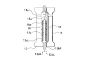
- FIG. 15 is a cross-sectional view of the dehydration unit at the time of the primary press-fitting (cross-sectional view taken along line VIIA-VIIA in FIG. 6).
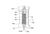
- FIG. 16 is a cross-sectional view of the dehydration unit at the time of secondary press-fitting (at the time of stock solution press-fitting) (cross-sectional view taken along line VIIB-VIIB in FIG. 6).
- FIG. 17 is a cross-sectional view of the dehydration unit at the time of the pressing step (cross-sectional view taken along the line VIIB-VIIB in FIG. 6).
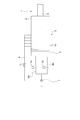
- FIG. 1 is a side view of a filter cloth traveling filter press 1 according to an embodiment of the present invention. 1 to 3, the stock solution is indicated by RL and the filtrate is indicated by FL.
- the filter press 1 includes a front frame 2, a rear frame 3, a guide rail 4 supported by the front frame 2 and the rear frame 3, and a filter plate 10 provided in parallel on the guide rail 4 in the horizontal direction. 5 is provided.
- the dehydrating unit 5 is movably supported on the guide rail 4.
- the dehydrating unit 5 is fastened by an opening / closing device 6 that reciprocates along the guide rail 4 by the driving force of, for example, an electric cylinder or a hydraulic cylinder.
- FIG. 2 is a plan view of the filter press 1.
- the stock solution supply pump 7 supplies the stock solution to the filter press 1 via the stock solution supply pipes 8a and 8b.
- the stock solution supply pipes 8a and 8b are provided with valves Va and Vb, respectively.
- the number of stock solution supply pipes varies depending on the number of pairs of filter cloths provided between the filter plates. For example, if three pairs of filter cloths are provided between the filter plates, the stock solution supply pipes are also three.
- a compressed fluid supply pipe 9 communicates with the dehydration unit 5.
- FIG. 3 is a sectional view of the dewatering unit of the filter press 1.
- the dehydrating unit 5 includes a plurality of filter plates 10 having a filter bed formed in a concave shape.
- the plurality of filter plates 10 are arranged to face each other and form a filtration space 12 between adjacent filter plates 10.
- One filter plate 10 has a diaphragm 11.
- the diaphragm 11 is expanded by injecting a pressure fluid therein.
- the filter cloth 13 is a pair of filter cloths 13a and 13b.
- One pair of filter cloths 13a includes a filter cloth 13aL and a filter cloth 13aR, and a filtration chamber 12a is formed between the filter cloth 13aL and the filter cloth 13aR.
- the other pair of filter cloths 13b includes a filter cloth 13bL and a filter cloth 13bR, and a filtration chamber 12b is formed between the filter cloth 13bL and the filter cloth 13bR.
- a stock solution supply path 14 for supplying a stock solution such as slurry to be dehydrated to the filtration chambers 12a and 12b is provided.
- a compressed water injection path 15 that penetrates the filter plate 10 and reaches the diaphragm 11 is formed.
- the compressed fluid supplied from the compressed fluid supply pipe 9 is injected into the diaphragm 11 through the compressed water injection path 15.
- a filtrate discharge path 16 is provided which communicates with the filtration bed and discharges the filtrate that has permeated from the filtration chambers 12 a and 12 b through the filter cloth 13. Even if the number of the pair of filter cloths provided between the filter plates is three or more, the filtrate can be similarly discharged.
- FIG. 4 is a cross-sectional view of the main part of the lower part of the filter plate 10.
- the filter plate 10 is provided with a filtrate discharge path 16.
- a discharge path 16a for discharging the filtrate from the filtration bed is provided.
- Rejectors 32 such as semi-rigid rubber are fixed to the two filter cloths 13aR and 13bL in the center of the filtration space 12 on the surface where they abut.
- the rejector 32 is sandwiched by a part of the sealing surface of the filter plate 10 and forms a gap that allows the filtrate to pass through the discharge path 16b.
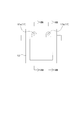
- FIG. 5 is a lower front view of the two filter cloths 13aR and 13bL at the center of the filtration space 12.
- FIG. The rejector 32 is provided in parallel with the lower portion of the filter cloth 13, and is attached to a position where the discharge path 16 b of the filter plate 10 is not blocked by the rejector 32. Between a plurality of the rejectors 32, the cake is prevented from flowing out with a narrow width so that the cake is not formed in the discharge passage 16b. By providing the rejector 32, the flow path to the discharge path 16b is not blocked by the cake, and the filtrate is easily discharged. Further, the drainage may be performed only by the gap of the filter cloth 13 without providing the rejector 32.
- the dehydration unit 5 in which the filter plate 10 provided with the recesses on both sides and the filter plate 10 provided with the diaphragm 11 on both sides is used alternately is used, but the present invention is not limited to this.
- the dehydration unit 5 which provided the recessed part in the front, and paralleled the filter plate 10 which provided the diaphragm 11 in the back surface.
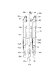
- FIG. 6 is a front view of the filter plate 10.
- two pairs of filter cloths 13a and 13b are provided in one filtration space 12, and each of the filtrations formed by the two pairs of filter cloths 13a and 13b.
- Stock solution supply paths 14a and 14b for supplying the stock solution to the chambers 12a and 12b are provided separately.
- a pair of filter cloth 13 of this invention is not limited to two sets. For example, three or more pairs of filter cloths 13a, 13b,... Are provided in one filtration space 12, and each filtration chamber is formed by a plurality of pairs of filter cloths 13a, 13b,.
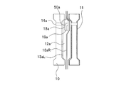
- 7A and 7B are cross-sectional views of the filter plate 10.
- 7A is a sectional view taken along the line VIIA-VIIA in FIG. 6, and
- FIG. 7B is a sectional view taken along the line VIIB-VIIB in FIG.
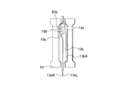
- Two pairs of filter cloths 13a and 13b are arranged between the filter plates 10 and 10, and the pair of filter cloths 13a and 13b are respectively provided at locations corresponding to the stock solution supply paths 14a and 14b on the upper side of the filter plate 10.
- Liquid supply plates 18a and 18b are provided.
- One liquid supply plate 18a is provided between one pair of filter cloths 13aL and 13aR, and the other liquid supply plate 18b is provided between the other pair of filter cloths 13bL and 13bR.
- the liquid supply plates 18a and 18b include openings 50a and 50b through which the stock solution supply paths 14a and 14b communicate, and distribution ports 19a and 19b through the openings 50a and 50b toward the filtration chambers 12a and 12b. That is, the stock solution supply paths 14a and 14b, the openings 50a and 50b, the distribution ports 19a and 19b, and the filtration chambers 12a and 12b communicate with each other.
- the stock solution supplied to the stock solution supply path 14a flows into the filtration chamber 12a through the opening 50a and the distribution port 19a of the liquid supply plate 18a, and the stock solution supplied to the stock solution supply path 14b is Then, the liquid flows into the filtration chamber 12b through the opening 50b of the liquid supply plate 18b and the distribution port 19b.
- the stock solution can be supplied by providing the liquid supply plate 18 in the same manner.
- the dehydration unit 5 which provided the filter board 10 which provided the recessed part on both surfaces and the filter board 10 which provided the diaphragm 11 on both surfaces was used alternately, when a pair of filter cloth 13 is provided three sets Alternatively, for example, a dewatering unit 5 may be provided in which a filter plate 10 provided with a concave portion on the front surface and provided with a diaphragm 11 on the rear surface is arranged in parallel.
- FIG. 8 is a schematic side view of the cake peeling apparatus of the filter press 1 according to the embodiment of the present invention.
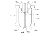
- This cake peeling apparatus includes a scraper 30 that can move up and down between the filter cloths 13bL and 13bR, and peels the cake attached to the four filter cloths 13aL, 13aR, 13bL, and 13bR.
- FIG. 9 is a schematic side view of another example of the cake peeling apparatus according to the embodiment of the present invention.
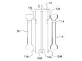
- the cake peeling device of this other example includes a vibration device 31 for vibrating the filter cloth 13 on the top of the filter cloth 13, and peels the cake adhering to the four filter cloths 13aL, 13aR, 13bL, 13bR. .
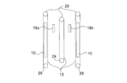
- FIGS. 10A and 10B are schematic side views of the annular filter cloth cake peeling apparatus according to the embodiment of the present invention.
- an annular filter cloth 13 is wound around a roll 29 provided above and below the filter plate 10, and annularly formed on the roll 29 provided above and below between the filter plates 10 and 10.
- a filter cloth 13 is hung around. By rotating the roll 29 by the driving source, the filter cloth 13 can be run and the cake can be peeled off.
- FIG. 10B a roll 29 provided below the filter plates 10 and 10, a roll 29 provided above the liquid supply plates 18a and 18b, and a roll 29 provided below the liquid supply plates 18a and 18b.
- a filter cloth 13 is hung around. By rotating the roll 29 by the driving source, the filter cloth 13 can be run and the cake can be peeled off.
- the roll 29 and the liquid supply plate 18 are provided by a known technique.
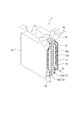
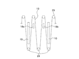
- FIG. 11 is a perspective view of a pair of filter cloths 13 a and 13 b suspended between the filter plates 10 of the filter press 1.
- two pairs of filter cloths 13 are provided side by side in the filtration space 12.
- the upper edges of the filter cloths of the pair of filter cloths 13 are joined together, and an upper filter cloth core 20 is attached to the joined parts.
- Lower filter cloth cores 21 are respectively attached to the lower edge portions of the pair of filter cloths 13 joined to the upper edge portions.
- two openings 13 c communicating with the stock solution supply paths 14 a and 14 b are provided at the upper part of each filter cloth 13, and a liquid supply plate 18 is provided in one of the openings 13 c.
- the liquid supply plate 18 allows the stock solution to flow between the filter cloths of the pair of filter cloths 13.
- the liquid supply plates 18a and 18b of the two pairs of filter cloths 13a and 13b are provided symmetrically.
- the opening 52a where the liquid supply plate 18a of one pair of filter cloths 13a is not provided corresponds to the opening 50b of the liquid supply plate 18b provided above the other pair of filter cloths 13b.
- the opening 50a of the liquid supply plate 18a of one pair of filter cloths 13a corresponds to the opening 52b in which the liquid supply plate 18b of the other pair of filter cloths 13b is not provided. Therefore, when the filter plate 10 is closed, these openings 50a, 50b, 52a, 52b communicate with each other to form the stock solution supply paths 14a, 14b.
- the filter cloths 13 When three pairs of filter cloths 13 are provided, the filter cloths 13 have three openings, and a liquid supply plate 18 is provided in each corresponding opening so that the stock solution can be supplied between the pair of filter cloths 13. It becomes possible.
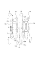
- FIG. 12 is a side view of the cake peeling device and the filter cloth hanging device before running the filter cloth of the filter cloth running filter press 1 according to the embodiment of the present invention.
- the lower end of the filter cloth 13 is hung around the rolls 26 and 27, and the lower end of the filter cloth 13 is lifted by a chain or the like to run the filtration surface downward to peel the cake.
- the filter cloth 13 used for the filter cloth traveling type includes two pairs of filter cloths, and uses a total of four filter cloths 13aL, 13aR, 13bL, and 13bR.
- the stock solution supplied to the liquid supply plates 18a and 18b is supplied from the distribution ports 19a and 19b.
- the cake that flows between the pair of filter cloths 13 and dehydrated is formed between the pair of filter cloths 13.
- FIG. 13 is a side view of the cake peeling device and the filter cloth suspending device after the filter cloth traveling of the filter cloth traveling filter press 1 according to the embodiment of the present invention.
- Each lower filter cloth mandrel 21 is pulled up by a traveling chain 22 wound around the filter plate upper sprocket 24 and the filter plate upper sprocket 28. For this reason, the filter cloth 13 travels downward, and then travels upward in order from the lower part of the filter cloth 13 via the filter plate return roll (return roll) 26 or the inter-filter plate return roll (return roll) 27.
- the filter plate upper sprocket 24 and the filter plate upper sprocket 28 are reversely rotated to return the filter cloth 13 to the original position and start dewatering.
- the inter-filter plate upper sprocket 28 and the inter-filter plate return roll 27 are arranged so as to be positioned in the middle of the filter plate 10 that is opened and closed by a known method.
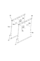
- FIG. 14 is a side view of an essential part of a filter cloth suspending device suspended between the filter plates 10 of the filter cloth traveling filter press 1 according to the embodiment of the present invention.
- Upper filter cloth cores 20 are inserted through the upper edges of the two pairs of filter cloths 13a and 13b, and a pair of drive chains 22, 22 are connected.
- a pair of upper brackets 23, 23 are erected on the shoulder portion of the filter plate 10, and a filter plate upper sprocket 24 is pivotally attached to the upper bracket 23.
- a drive chain 22 a of one pair of filter cloths 13 a is wound around the filter plate upper sprocket 24.
- an upper inter-filter plate sprocket 28 is provided at the upper part between the filter plates 10, and the drive chain 22b of the other pair of filter cloths 13b is wound around.
- One ends of the drive chains 22a and 22b are connected to upper filter cloth cores 20 and 20 provided at upper edges of the filter cloths 13a and 13b, respectively.
- the other end of the drive chain 22 a that is wound around the filter plate upper sprocket 24 and suspends the filter cloth 13 a is suspended from the back surface side of the filter plate 10.
- a pair of filter plate return rolls 26 are supported on a lower bracket 25 that hangs from the lower ends of both sides of the filter plate 10.
- the lower part of the filter cloth 13aL is wound around one filter plate return roll 26b, and the lower filter cloth core 21 of the filter cloth 13aL and the drive chain 22a suspended from the back side of the filter plate 10 are locked.
- a pair of inter-filter return rolls 27 are provided below the filter plates 10.
- the lower part of the filter cloth 13aR is hung on one of the return rolls 27a between the filter plates, and the lower filter cloth core 21 of the filter cloth 13aR is connected to the other end of the drive chain 22b hung on the upper sprocket 28 between the filter boards. ing.
- the lower part of the filter cloth 13bL is looped around the other filter plate return roll 27b and connected to the drive chain 22b.
- the lower part of the filter cloth 13bR is wound around the other filter plate return roll 26a of the adjacent filter plate 10, and the lower filter cloth core 21 of the filter cloth 13bR is placed on the back side from the filter plate upper sprocket 24 of the adjacent filter plate 10.
- the drive chain 22a is suspended.
- one filter cloth of a pair of filter cloths 13 connects the other filter cloth and the lower end edge of a pair of adjacent filter cloths 13, and inserts the lower filter cloth core 21 into the connecting portion, thereby It is also possible to constitute the filter cloth 13 of the filter press with a single sheet of filter cloth 13. In this case, even with a single filter cloth, one filtration space 12 can be divided into two, and separation by running of the filter cloth is also possible.
- the filter plate upper sprocket 24, the filter plate upper sprocket 28, the filter plate return roll 26, and the filter plate return roll 27 are set. If necessary, a roll 29 may be additionally provided as shown in FIGS.
- the filter cloth 13 When the cake is discharged, the filter cloth 13 is caused to travel downward by rotating the filter plate upper sprocket 24 and the inter-filter upper sprocket 28 with a drive source (not shown), and the lower filter cloth core 21 is moved by the drive chain 22. Be raised.
- the cake with good peelability is dropped and discharged together with the opening of the filter plate 10, and the cake attached to the filter cloths 13aL, 13aR, 13bL, 13bR is sharpened by the filter cloth 13 at the filter plate return roll 26 and the inter-filter return roll 27. It peels by being reversed.
- the filtration method in the filter press 1 that performs solid-liquid separation of the stock solution by sequentially supplying the stock solution to the filtration chamber 12a and the filtration chamber 12b is a first example, and a plurality of (two sets in this embodiment) filtration chambers 12a are used.
- the filtration method in the filter press 1 that performs solid-liquid separation of the stock solution by simultaneously press-fitting the stock solution into 12b will be described below as a second embodiment.
- the filter plate 10 provided in parallel is closed and tightened by the switchgear 6 to form a large number of filtration spaces 12, and the supply port 17 is connected to form the stock solution supply path 14.
- FIG. 15 is a cross-sectional view of the dehydrating unit during the primary press-fitting process according to the embodiment of the present invention.
- the cake is indicated by CK.
- the stock solution supply pump 7 While opening the valve Va provided in the stock solution supply pipe 8a, the stock solution supply pump 7 is started.
- the stock solution is a filter cloth sandwiching the liquid supply plate 18a among the four filter cloths 13aL, 13aR, 13bL, and 13bR provided in the filtration space 12 from the stock solution supply pipe 8a through the stock solution supply path 14a and the liquid supply plate 18a. It is press-fitted between 13aL and 13aR (filtration chamber 12a).
- the stock solution is sufficiently distributed in each filtration chamber 12a and is solid-liquid separated by the filter cloths 13aL and 13aR stretched in the filtration space 12, and the filtration action by the press-fitting pressure proceeds.
- the filtrate that has passed through the filter cloths 13aL and 13aR and separated into solid and liquid is discharged from the filtrate discharge path 16 to the outside.
- the primary press-fitting process continues for a predetermined time. Solid content accumulates in the filtration chamber 12a to form a cake.
- the stock solution having good dehydration properties may be dehydrated by the primary press-fitting filtration chamber 12a, and then the dehydration step may be completed, and the plate opening step may be started.
- FIG. 16 is a cross-sectional view of the dehydration unit at the time of the secondary press-fitting process according to the embodiment of the present invention.
- secondary press-fitting is performed in which the stock solution is press-fitted into the filtration chamber 12b to separate into solid and liquid.
- the valve Va is closed to stop the press-fitting into the filtration chamber 12a, and the valve Vb provided in the stock solution supply pipe 8b is opened to switch the stock solution supply flow path.
- the stock solution is press-fitted between the filter cloths 13bL and 13bR (filtration chamber 12b) sandwiching the liquid supply plate 18b through the stock solution supply path 14b and the liquid supply plate 18b from the stock solution supply pipe 8b.
- the undiluted solution is sufficiently distributed in each filtration chamber 12b and is solid-liquid separated by the filter cloths 13bL and 13bR stretched in the filtration space 12, and the filtering action by the press-fitting pressure proceeds.
- the filter cloth 13aR has a low permeability because a cake is adhered during the primary press-fitting, and the filtrate does not pass through the secondary press-fitting. Therefore, the filtrate passes between the filter cloths 13aR and 13bL and is discharged from the lower discharge path 16b.
- a net or the like may be attached between the filter cloths 13aR and 13bL in order to enhance drainage.
- the discharged liquid passes through the gap of the filter cloth 13 and is discharged from the filtrate discharge path 16b provided below.
- the filtrate that has permeated the filter cloth 13bR and separated into solid and liquid is discharged to the outside from the filtrate discharge path 16a.
- the filtration chamber 12b can be further expanded to give a pressing action to the cake in the filtration chamber 12a.
- FIG. 17 is a cross-sectional view of the dehydration unit during the pressing process according to the embodiment of the present invention.
- the diaphragm 11 in the filtration space 12 is expanded, and the pressing process is performed on the cake in the filtration chambers 12a and 12b.
- the compressed fluid supply device is activated.
- the compressed fluid is supplied into the diaphragm 11 formed in the filter plate 10 through the compressed fluid supply pipe 9 and the compressed water injection path 15 to expand the diaphragm 11.
- the stock solution is solid-liquid separated by filter cloths 13aL, 13aR, 13bL, 13bR by squeezing with the diaphragm 11, and the filtrate is discharged from the filtrate between the filtrate discharge path 16a provided in the filtration bed and the filter plate 10. It is discharged out of the machine via the path 16b.
- the filtration chambers 12a and 12b are simultaneously squeezed in the squeezing process, so that a cake having a uniform moisture content can be formed. It becomes possible.
- the pressing process continues for a fixed period of time.
- the pressing process may be omitted. In that case, the diaphragm 11 provided in the filter plate 10 becomes unnecessary.
- the squeezing step may be performed once after the primary press-fitting and once again after the secondary press-fitting.
- the filtration (solid-liquid separation) method of the filter press according to the second embodiment will be described.
- the filter press 1 having two pairs of filter cloths provided between the filter plates will be described.
- the solid-liquid separation method of the filter press according to the second embodiment has three pairs of filter cloths provided between the filter plates. It is applicable also to the filter press 1 which is a set or more. 16 and 17 can also be used to explain the filtration method of the filter press according to the second embodiment.
- the filter plate 10 provided in parallel is closed and tightened by the opening / closing device 6 to form a large number of filtration spaces 12, and the supply port 17 is connected to form the stock solution supply path 14.
- FIG. 16 is a cross-sectional view of the dehydration unit during the stock solution press-fitting process according to the embodiment of the present invention.
- the valves Va and Vb provided in the stock solution supply pipes 8a and 8b are simultaneously opened, and the stock solution supply pump 7 is started.
- the stock solution is simultaneously press-fitted from the stock solution supply pipes 8a and 8b into the filtration chambers 12a and 12b provided between the filter plates 10 and 10 through the stock solution supply paths 14a and 14b and the liquid supply plates 18a and 18b.
- the undiluted solution is evenly distributed in the filtration chambers 12a and 12b, and the filtrate is discharged between the filter plate 10 and the filter cloth 13aL, between the filter plate 10 and the filter cloth 13bR, and further between the filter cloth 13aR and the filter cloth 13bL.
- the filtrate that has permeated through the filter cloth 13 is discharged to the outside from the filtrate discharge path 16 through a discharge path 16 a provided in the filtration bed and a discharge path 16 b provided below the filter plate.
- the press-fitting process continues for a fixed period of time. Solid content accumulates in the filtration chambers 12a and 12b to form a cake.
- FIG. 17 is a cross-sectional view of the dehydration unit during the pressing process according to the embodiment of the present invention.
- the diaphragm 11 of the filter plate 10 is expanded, and a pressing process is performed on the cakes in the filtration chambers 12a and 12b.
- the compressed fluid supply device is activated.
- the compressed fluid is supplied into the diaphragm 11 formed in the filter plate 10 through the compressed fluid supply pipe 9 and the compressed water injection path 15 to expand the diaphragm 11.
- the cake is squeezed with the filter cloths 13aL, 13aR, 13bL, and 13bR by squeezing with the diaphragm 11, and the filtrate is discharged.
- the filtrate is discharged from the filtrate discharge path 16 to the outside through a discharge path 16a provided in the filtration bed and a discharge path 16b provided below the filter plate.
- the filtration chambers 12a and 12b are simultaneously squeezed in the squeezing process, so a cake with a uniform moisture content can be formed. It becomes.
- the pressing process continues for a fixed period of time.
- the pressing process may be omitted. In that case, the diaphragm 11 provided in the filter plate 10 becomes unnecessary.
- the filter press 1 is provided with four filter cloths 13 in one filtration space between the filter plates 10 for solid-liquid separation, and can increase the filtration surface to four surfaces. By improving the operation method, the processing capacity can be improved and the number of filter rooms can be reduced.
- the operation method can be switched according to the dewatering property of the sludge. If the dewatering property is good, only the primary press-fitting can be used. .
- the filter press 1 is compatible with various operation methods such as simultaneously injecting the stock solution into the two filtration chambers 12a and 12b and again injecting into the filtration chamber 12a that has been subjected to the primary injection after the secondary injection. it can.
- the filter press 1 is provided with four filter cloths 13 in one filtration space between the filter plates 10 for solid-liquid separation, and the cake is peeled by running the filter cloths 13. Can do. A mechanism that can run even with four filter cloths 13 is used, and it corresponds to a filter press 1 having a form different from the usual, in which four filter cloths 13 are provided in the filtration space.
- the filter press 1 is provided with a plurality of a pair of filter cloths 13 in one filtration space between the filter plates 10, can increase the filtration surface than usual, and devise an operation method. As a result, the processing capacity can be improved.
- the operation method can be switched according to the dewatering property of the sludge, and when the dewatering property is good, it is possible to appropriately cope with the change of the sludge property by squeezing.
- this filter press 1 can respond
- Japanese Patent Application No. 2013-052946 (Application Date: March 15, 2013)
- Japanese Patent Application No. 2013-052948 (Application Date: March 15, 2013)
- Japanese Patent Application No. 2013-155124 (Application Date: July 2013) The entire contents of May 26) are incorporated herein.
Landscapes
- Chemical & Material Sciences (AREA)
- Chemical Kinetics & Catalysis (AREA)
- Filtration Of Liquid (AREA)
Abstract
L'invention concerne un filtre-presse (1) présentant : une première et une deuxième plaque de filtre (10) qui sont disposées parallèlement et forment un espace de filtration entre elles ; et une pluralité de paires de toiles filtrantes (13a, 13b) qui sont disposées dans l'espace de filtration et qui forment, entre chaque paire de toiles filtrantes (13aR, 13aL, 13bR, 13bL), une chambre de filtration (12a, 12b) pour filtrer un liquide de départ. Dans ce procédé de filtration dans le filtre-presse (1), la séparation solide/liquide du liquide de départ est réalisée soit par alimentation séquentielle de la première chambre de filtration (12a) et de la deuxième chambre de filtration (12b) en liquide de départ, soit par injection simultanée du liquide de départ dans la pluralité de chambres de filtration (12).
Applications Claiming Priority (6)
| Application Number | Priority Date | Filing Date | Title |
|---|---|---|---|
| JP2013-052946 | 2013-03-15 | ||
| JP2013-052948 | 2013-03-15 | ||
| JP2013052946A JP5874983B2 (ja) | 2013-03-15 | 2013-03-15 | フィルタープレス |
| JP2013052948A JP5874984B2 (ja) | 2013-03-15 | 2013-03-15 | フィルタープレスのろ布吊設装置 |
| JP2013-155124 | 2013-07-26 | ||
| JP2013155124A JP6024917B2 (ja) | 2013-07-26 | 2013-07-26 | フィルタープレスの脱水方法 |
Publications (1)
| Publication Number | Publication Date |
|---|---|
| WO2014142073A1 true WO2014142073A1 (fr) | 2014-09-18 |
Family
ID=51536729
Family Applications (1)
| Application Number | Title | Priority Date | Filing Date |
|---|---|---|---|
| PCT/JP2014/056178 Ceased WO2014142073A1 (fr) | 2013-03-15 | 2014-03-10 | Filtre-presse et procédé de filtration dans un filtre-presse |
Country Status (2)
| Country | Link |
|---|---|
| TW (1) | TW201505697A (fr) |
| WO (1) | WO2014142073A1 (fr) |
Cited By (3)
| Publication number | Priority date | Publication date | Assignee | Title |
|---|---|---|---|---|
| JP2015123427A (ja) * | 2013-12-27 | 2015-07-06 | 株式会社石垣 | フィルタープレスのろ液排出構造 |
| CN109731377A (zh) * | 2019-03-19 | 2019-05-10 | 景津环保股份有限公司 | 一种两端进料双缸压紧压滤机 |
| JP2021053577A (ja) * | 2019-09-30 | 2021-04-08 | 株式会社三鷹工業所 | フィルタプレス |
Families Citing this family (1)
| Publication number | Priority date | Publication date | Assignee | Title |
|---|---|---|---|---|
| CN115999215A (zh) * | 2022-07-28 | 2023-04-25 | 第一环保(深圳)股份有限公司 | 高效自动缷泥压滤机 |
Citations (2)
| Publication number | Priority date | Publication date | Assignee | Title |
|---|---|---|---|---|
| JPH1076110A (ja) * | 1996-09-05 | 1998-03-24 | Ishigaki:Kk | トップフィード型単式フィルタープレス用濾布の保護布 |
| JP2004216361A (ja) * | 2002-11-19 | 2004-08-05 | Nippon Enbairo Kogyo Kk | 濾過機および濾過方法 |
-
2014
- 2014-03-10 WO PCT/JP2014/056178 patent/WO2014142073A1/fr not_active Ceased
- 2014-03-13 TW TW103109047A patent/TW201505697A/zh unknown
Patent Citations (2)
| Publication number | Priority date | Publication date | Assignee | Title |
|---|---|---|---|---|
| JPH1076110A (ja) * | 1996-09-05 | 1998-03-24 | Ishigaki:Kk | トップフィード型単式フィルタープレス用濾布の保護布 |
| JP2004216361A (ja) * | 2002-11-19 | 2004-08-05 | Nippon Enbairo Kogyo Kk | 濾過機および濾過方法 |
Cited By (4)
| Publication number | Priority date | Publication date | Assignee | Title |
|---|---|---|---|---|
| JP2015123427A (ja) * | 2013-12-27 | 2015-07-06 | 株式会社石垣 | フィルタープレスのろ液排出構造 |
| CN109731377A (zh) * | 2019-03-19 | 2019-05-10 | 景津环保股份有限公司 | 一种两端进料双缸压紧压滤机 |
| JP2021053577A (ja) * | 2019-09-30 | 2021-04-08 | 株式会社三鷹工業所 | フィルタプレス |
| JP7281189B2 (ja) | 2019-09-30 | 2023-05-25 | 株式会社三鷹工業所 | フィルタプレス |
Also Published As
| Publication number | Publication date |
|---|---|
| TW201505697A (zh) | 2015-02-16 |
Similar Documents
| Publication | Publication Date | Title |
|---|---|---|
| JP7069483B2 (ja) | フィルタープレスの脱水ケーキ洗浄方法 | |
| CN213668083U (zh) | 一种高压进料式滤板以及高压进料式压滤机 | |
| CN207237401U (zh) | 有移动滤板的压滤装置 | |
| JP7070096B2 (ja) | フィルタープレスの運転方法 | |
| TW201505697A (zh) | 壓濾機及壓濾機之過濾方法 | |
| JP5874983B2 (ja) | フィルタープレス | |
| JP6086325B2 (ja) | フィルタープレスのろ液排出構造 | |
| JP5809922B2 (ja) | フィルタプレス脱水装置 | |
| JP5999581B2 (ja) | フィルタープレス | |
| JP4936962B2 (ja) | フィルタープレス装置およびそのケーキ除去方法 | |
| JP6024917B2 (ja) | フィルタープレスの脱水方法 | |
| JP5999580B2 (ja) | フィルタープレスの運転方法 | |
| JP5874984B2 (ja) | フィルタープレスのろ布吊設装置 | |
| JP3447767B2 (ja) | 逆洗可能なフイルター装置及び該フイルターの逆洗方法 | |
| JP7634820B2 (ja) | フィルタープレスの圧搾膜及び運転方法 | |
| JPH0356763B2 (fr) | ||
| JP5907478B2 (ja) | フィルタープレスのろ布吊設装置 | |
| JP5483263B2 (ja) | フィルタープレスの圧搾脱水方法並びに圧搾脱水装置 | |
| JP3940352B2 (ja) | フィルタプレス及びフィルタプレスの圧搾方法 | |
| JP2003112199A (ja) | 高加圧型脱水機 | |
| JP2015164708A (ja) | フィルタープレスのろ布走行機構 | |
| KR101253643B1 (ko) | 여과판 | |
| JP2004216361A (ja) | 濾過機および濾過方法 | |
| KR101407058B1 (ko) | 돌기부가 형성된 필터프레스용 여과판 | |
| KR20100053142A (ko) | 듀얼 필터프레스 |
Legal Events
| Date | Code | Title | Description |
|---|---|---|---|
| 121 | Ep: the epo has been informed by wipo that ep was designated in this application |
Ref document number: 14764926 Country of ref document: EP Kind code of ref document: A1 |
|
| NENP | Non-entry into the national phase |
Ref country code: DE |
|
| 122 | Ep: pct application non-entry in european phase |
Ref document number: 14764926 Country of ref document: EP Kind code of ref document: A1 |