WO2014142100A1 - 磁気特性に優れる無方向性電磁鋼板 - Google Patents
磁気特性に優れる無方向性電磁鋼板 Download PDFInfo
- Publication number
- WO2014142100A1 WO2014142100A1 PCT/JP2014/056267 JP2014056267W WO2014142100A1 WO 2014142100 A1 WO2014142100 A1 WO 2014142100A1 JP 2014056267 W JP2014056267 W JP 2014056267W WO 2014142100 A1 WO2014142100 A1 WO 2014142100A1
- Authority
- WO
- WIPO (PCT)
- Prior art keywords
- mass
- magnetic flux
- flux density
- less
- oriented electrical
- Prior art date
- Legal status (The legal status is an assumption and is not a legal conclusion. Google has not performed a legal analysis and makes no representation as to the accuracy of the status listed.)
- Ceased
Links
Images


Classifications
-
- H—ELECTRICITY
- H01—ELECTRIC ELEMENTS
- H01F—MAGNETS; INDUCTANCES; TRANSFORMERS; SELECTION OF MATERIALS FOR THEIR MAGNETIC PROPERTIES
- H01F1/00—Magnets or magnetic bodies characterised by the magnetic materials therefor; Selection of materials for their magnetic properties
- H01F1/01—Magnets or magnetic bodies characterised by the magnetic materials therefor; Selection of materials for their magnetic properties of inorganic materials
- H01F1/03—Magnets or magnetic bodies characterised by the magnetic materials therefor; Selection of materials for their magnetic properties of inorganic materials characterised by their coercivity
- H01F1/12—Magnets or magnetic bodies characterised by the magnetic materials therefor; Selection of materials for their magnetic properties of inorganic materials characterised by their coercivity of soft-magnetic materials
- H01F1/14—Magnets or magnetic bodies characterised by the magnetic materials therefor; Selection of materials for their magnetic properties of inorganic materials characterised by their coercivity of soft-magnetic materials metals or alloys
- H01F1/147—Alloys characterised by their composition
- H01F1/14766—Fe-Si based alloys
- H01F1/14775—Fe-Si based alloys in the form of sheets
-
- C—CHEMISTRY; METALLURGY
- C22—METALLURGY; FERROUS OR NON-FERROUS ALLOYS; TREATMENT OF ALLOYS OR NON-FERROUS METALS
- C22C—ALLOYS
- C22C38/00—Ferrous alloys, e.g. steel alloys
-
- C—CHEMISTRY; METALLURGY
- C22—METALLURGY; FERROUS OR NON-FERROUS ALLOYS; TREATMENT OF ALLOYS OR NON-FERROUS METALS
- C22C—ALLOYS
- C22C38/00—Ferrous alloys, e.g. steel alloys
- C22C38/001—Ferrous alloys, e.g. steel alloys containing N
-
- C—CHEMISTRY; METALLURGY
- C22—METALLURGY; FERROUS OR NON-FERROUS ALLOYS; TREATMENT OF ALLOYS OR NON-FERROUS METALS
- C22C—ALLOYS
- C22C38/00—Ferrous alloys, e.g. steel alloys
- C22C38/002—Ferrous alloys, e.g. steel alloys containing In, Mg, or other elements not provided for in one single group C22C38/001 - C22C38/60
-
- C—CHEMISTRY; METALLURGY
- C22—METALLURGY; FERROUS OR NON-FERROUS ALLOYS; TREATMENT OF ALLOYS OR NON-FERROUS METALS
- C22C—ALLOYS
- C22C38/00—Ferrous alloys, e.g. steel alloys
- C22C38/004—Very low carbon steels, i.e. having a carbon content of less than 0,01%
-
- C—CHEMISTRY; METALLURGY
- C22—METALLURGY; FERROUS OR NON-FERROUS ALLOYS; TREATMENT OF ALLOYS OR NON-FERROUS METALS
- C22C—ALLOYS
- C22C38/00—Ferrous alloys, e.g. steel alloys
- C22C38/008—Ferrous alloys, e.g. steel alloys containing tin
-
- C—CHEMISTRY; METALLURGY
- C22—METALLURGY; FERROUS OR NON-FERROUS ALLOYS; TREATMENT OF ALLOYS OR NON-FERROUS METALS
- C22C—ALLOYS
- C22C38/00—Ferrous alloys, e.g. steel alloys
- C22C38/02—Ferrous alloys, e.g. steel alloys containing silicon
-
- C—CHEMISTRY; METALLURGY
- C22—METALLURGY; FERROUS OR NON-FERROUS ALLOYS; TREATMENT OF ALLOYS OR NON-FERROUS METALS
- C22C—ALLOYS
- C22C38/00—Ferrous alloys, e.g. steel alloys
- C22C38/04—Ferrous alloys, e.g. steel alloys containing manganese
-
- C—CHEMISTRY; METALLURGY
- C22—METALLURGY; FERROUS OR NON-FERROUS ALLOYS; TREATMENT OF ALLOYS OR NON-FERROUS METALS
- C22C—ALLOYS
- C22C38/00—Ferrous alloys, e.g. steel alloys
- C22C38/06—Ferrous alloys, e.g. steel alloys containing aluminium
-
- C—CHEMISTRY; METALLURGY
- C22—METALLURGY; FERROUS OR NON-FERROUS ALLOYS; TREATMENT OF ALLOYS OR NON-FERROUS METALS
- C22C—ALLOYS
- C22C38/00—Ferrous alloys, e.g. steel alloys
- C22C38/60—Ferrous alloys, e.g. steel alloys containing lead, selenium, tellurium, or antimony, or more than 0.04% by weight of sulfur
-
- H—ELECTRICITY
- H01—ELECTRIC ELEMENTS
- H01F—MAGNETS; INDUCTANCES; TRANSFORMERS; SELECTION OF MATERIALS FOR THEIR MAGNETIC PROPERTIES
- H01F1/00—Magnets or magnetic bodies characterised by the magnetic materials therefor; Selection of materials for their magnetic properties
- H01F1/01—Magnets or magnetic bodies characterised by the magnetic materials therefor; Selection of materials for their magnetic properties of inorganic materials
- H01F1/03—Magnets or magnetic bodies characterised by the magnetic materials therefor; Selection of materials for their magnetic properties of inorganic materials characterised by their coercivity
- H01F1/12—Magnets or magnetic bodies characterised by the magnetic materials therefor; Selection of materials for their magnetic properties of inorganic materials characterised by their coercivity of soft-magnetic materials
- H01F1/14—Magnets or magnetic bodies characterised by the magnetic materials therefor; Selection of materials for their magnetic properties of inorganic materials characterised by their coercivity of soft-magnetic materials metals or alloys
- H01F1/147—Alloys characterised by their composition
-
- H—ELECTRICITY
- H01—ELECTRIC ELEMENTS
- H01F—MAGNETS; INDUCTANCES; TRANSFORMERS; SELECTION OF MATERIALS FOR THEIR MAGNETIC PROPERTIES
- H01F1/00—Magnets or magnetic bodies characterised by the magnetic materials therefor; Selection of materials for their magnetic properties
- H01F1/01—Magnets or magnetic bodies characterised by the magnetic materials therefor; Selection of materials for their magnetic properties of inorganic materials
- H01F1/03—Magnets or magnetic bodies characterised by the magnetic materials therefor; Selection of materials for their magnetic properties of inorganic materials characterised by their coercivity
- H01F1/12—Magnets or magnetic bodies characterised by the magnetic materials therefor; Selection of materials for their magnetic properties of inorganic materials characterised by their coercivity of soft-magnetic materials
- H01F1/14—Magnets or magnetic bodies characterised by the magnetic materials therefor; Selection of materials for their magnetic properties of inorganic materials characterised by their coercivity of soft-magnetic materials metals or alloys
- H01F1/16—Magnets or magnetic bodies characterised by the magnetic materials therefor; Selection of materials for their magnetic properties of inorganic materials characterised by their coercivity of soft-magnetic materials metals or alloys in the form of sheets
-
- C—CHEMISTRY; METALLURGY
- C21—METALLURGY OF IRON
- C21D—MODIFYING THE PHYSICAL STRUCTURE OF FERROUS METALS; GENERAL DEVICES FOR HEAT TREATMENT OF FERROUS OR NON-FERROUS METALS OR ALLOYS; MAKING METAL MALLEABLE, e.g. BY DECARBURISATION OR TEMPERING
- C21D8/00—Modifying the physical properties of ferrous metals or ferrous alloys by deformation combined with, or followed by, heat treatment
- C21D8/12—Modifying the physical properties of ferrous metals or ferrous alloys by deformation combined with, or followed by, heat treatment during manufacturing of articles with special electromagnetic properties
Definitions
- the present invention relates to a non-oriented electrical steel sheet having excellent magnetic properties, and particularly to a non-oriented electrical steel sheet having a high magnetic flux density.
- such an induction motor core material is required to have a low excitation effective current at a designed magnetic flux density in addition to low iron loss in a steel plate as a material. ing. In order to reduce the excitation current, it is effective to increase the magnetic flux density of the core material. Further, in recent years, drive motors used in hybrid vehicles and electric vehicles that have been rapidly spreading are required to have a high torque at the time of starting and accelerating, and thus further improvement in magnetic flux density is desired.
- Patent Document 1 discloses a non-oriented electrical steel sheet in which 0.1 to 5 mass% of Co is added to steel of Si ⁇ 4 mass%.
- non-oriented electrical steel sheets used for the motor, the excitation direction rotates within the plate surface when the motor rotates. Also affects the motor characteristics. Therefore, it is strongly desired that non-oriented electrical steel sheets not only have excellent magnetic properties in the L and C directions but also have a small difference in magnetic properties between the L and C directions, that is, low anisotropy. Yes.
- the present invention has been made in view of the above problems of the prior art, and an object thereof is to provide a non-oriented electrical steel sheet having a high magnetic flux density without causing an increase in manufacturing cost.
- the inventors have intensively studied to solve the above problems. As a result, it was found that by adding P to steel with reduced Al and further reducing As, it is possible to increase the magnetic flux density without requiring a special additive element, and the present invention is developed. It came to.
- the present invention includes C: 0.01 mass% or less, Si: 1 to 4 mass%, Mn: 0.05 to 3 mass%, P: 0.03 to 0.2 mass%, S: 0.01 mass% or less, Al : Non-oriented electrical steel sheet containing 0.004 mass% or less, N: 0.005 mass% or less, and As: 0.003 mass% or less, with the balance being composed of Fe and inevitable impurities.
- the non-oriented electrical steel sheet of the present invention further includes one or two selected from Sb: 0.001 to 0.1 mass% and Sn: 0.001 to 0.1 mass%. It is characterized by containing.
- non-oriented electrical steel sheet of the present invention may be one or two selected from Ca: 0.001 to 0.005 mass% and Mg: 0.001 to 0.005 mass% in addition to the above component composition. It contains seeds.
- the non-oriented electrical steel sheet of the present invention has a ratio (B 50L / B 50C ) of the magnetic flux density B 50L in the rolling direction (L direction) to the magnetic flux density B 50C in the direction perpendicular to the rolling direction (C direction). It is 05 or less.
- the non-oriented electrical steel sheet of the present invention is characterized in that the plate thickness is 0.05 to 0.30 mm.
- a non-oriented electrical steel sheet having a high magnetic flux density can be provided at a low cost. Therefore, a high-efficiency induction motor, a drive motor for a hybrid vehicle or an electric vehicle that requires high torque, a high power generation efficiency Can be suitably used as a core material of a high-efficiency generator that requires
- the content of Al and P is a graph showing the effect on the magnetic flux density B 50. It is a graph which shows the influence which content of Al and P has on the anisotropy ( B50L / B50C ) of magnetic flux density.
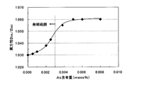
- Content of As is a graph showing the effect on the magnetic flux density B 50. It is a graph which shows the influence which content of As has on the anisotropy ( B50L / B50C ) of magnetic flux density.
- a test piece having a width of 30 mm and a length of 280 mm was taken from the cold-rolled annealed plate thus obtained, and the magnetic flux density B 50 was measured by the Epstein method. The result was obtained as the relationship between the P content and the magnetic flux density B 50. It was shown in FIG. Here, the magnetic flux density B 50, and the longitudinal direction of the rolling direction of the test piece, the longitudinal direction is measured using by half the perpendicular direction of the test piece in the rolling direction, is the magnetic flux density at a magnetizing force 5000A / m . From this figure, it can be seen that the Al-added steel does not improve the magnetic flux density even when P is added, but the Al-less steel improves the magnetic flux density by adding P of 0.03 mass% or more.
- the magnetic flux density B 50L in the rolling direction (L direction) and the magnetic flux density B in the direction perpendicular to the rolling direction (C direction) 50C was measured, and the influence of the P content on the anisotropy of the magnetic flux density was investigated.
- the ratio of the magnetic flux density B 50L in the rolling direction (L direction) to the magnetic flux density B 50C in the direction perpendicular to the rolling direction (C direction) (B 50L / B 50C ). was used. The closer this value is to 1, the smaller the anisotropy.
- the ratio (B 50L / B50C ) between the magnetic flux density B 50L in the rolling direction (L direction) and the magnetic flux density B 50C in the direction perpendicular to the rolling direction (C direction) (B 50L / B 50C ) is hereinafter simply referred to as “anisotropic (B 50L / B50C ) ".
- FIG. 2 shows the relationship between the P content and anisotropy (B 50L / B 50C ). From this figure, in the Al-less steel, anisotropy is reduced by adding P, and B is an index of anisotropy by making the addition amount of P 0.03 mass% or more. It can be seen that 50L / B 50C can be reduced to the development target of 1.05 or less. As described above, the reason why the anisotropy is improved by adding P to the Al-less steel is not yet fully clarified at this time. However, there is some change in the texture due to the segregation of P to the grain boundaries. It is assumed that the anisotropy of the magnetic flux density is reduced.
- C 0.0020 mass%, Si: 3.00 mass%, Mn: 0.20 mass%, P: 0.06 mass%, S: 0.0012 mass% , Al: 0.002 mass% and N: 0.0018 mass% steel is charged 10 times, hot rolled to a hot rolled sheet with a thickness of 1.6 mm, and annealed at 1000 ° C. for 30 sec. After pickling, pickling, and cold rolling to obtain a cold-rolled sheet having a thickness of 0.35 mm, finish annealing was performed at 1000 ° C. for 10 seconds in a 20 vol% H 2 -80 vol% N 2 atmosphere.
- C 0.0015 mass%, Si: 3.10 mass%, Mn: 0.15 mass%, P: 0.05 mass%, S: 0.0009 mass%, Al : 0.30 mass% and N: 0.0018 mass% steel (Al-added steel), C: 0.0016 mass%, Si: 3.00 mass%, Mn: 0.15 mass%, P: 0.05 mass%, S : As for the two types of steels of 0.0009 mass%, Al: 0.002 mass%, and N: 0.0020 mass% (Al-less steel).
- a test piece having a width of 30 mm and a length of 280 mm was taken from the cold-rolled annealed plate thus obtained, and the magnetic flux density B 50 was measured by the Epstein method. The result was obtained as the relationship between the As content and the magnetic flux density B 50. This is shown in FIG. From this figure, it can be seen that when the As content exceeds 0.003 mass%, the magnetic flux density decreases.
- B 50L and B 50C were measured using the test pieces obtained in the above experiment, and the relationship between the As content and (B 50L / B 50C ) is shown in FIG. From this figure, when the As content is 0.003 mass% or less, the anisotropy of the magnetic flux density becomes small, and the anisotropy index (B 50L / B 50C ) is the target value of 1.05 or less. I understood that I can do it. The reason for this is that when As is reduced, the amount of As segregated at the grain boundaries is reduced, and the segregation of P, which is the same segregating element, is promoted to the grain boundaries. As a result, the texture is improved. This is probably because the anisotropy reduction effect by the added P was further promoted.
- the present invention has been developed based on the above novel findings.
- C 0.01 mass% or less Since C will cause magnetic aging if it exceeds 0.01 mass% in the product plate, the upper limit is made 0.01 mass%. Preferably, it is 0.005 mass% or less.
- Si 1 to 4 mass% Since Si is an element effective in increasing the specific resistance of steel and reducing iron loss, 1 mass% or more is added in the present invention. On the other hand, if it exceeds 4 mass%, the excitation effective current increases remarkably. Therefore, the present invention sets Si in the range of 1 to 4 mass%. Preferably, the lower limit of Si is 2.0 mass%, and the upper limit is 3.5 mass%.
- Mn 0.05-3 mass% Mn needs to be added in an amount of 0.05 mass% or more in order to prevent brittleness during hot rolling. However, if it exceeds 3 mass%, the saturation magnetic flux density is lowered and the magnetic flux density is lowered. Therefore, Mn is set in the range of 0.05 to 3 mass%. Preferably, the lower limit of Mn is 0.05 mass%, and the upper limit is 2.0 mass%.
- P 0.03-0.2 mass% P is one of the important elements in the present invention.
- the steel becomes hard and cold rolling becomes difficult, so the upper limit is made 0.2 mass%.
- the lower limit of P is 0.05 mass%, and the upper limit is 0.10 mass%.
- S 0.01 mass% or less
- S is a harmful element that forms sulfides such as MnS, inhibits grain growth, and increases iron loss. Therefore, the upper limit is set to 0.01 mass%.
- S is also a grain boundary segregation type element, and when S increases, grain boundary segregation of P tends to be suppressed. Therefore, from the viewpoint of promoting grain boundary segregation of P, preferably 0.0009 mass% or less. It is.
- Al 0.004 mass% or less Al is one of the important elements in the present invention. If the content exceeds 0.004 mass%, the effect of improving the magnetic flux density by adding P described above cannot be obtained. 004 mass%. Preferably it is 0.002 mass% or less.
- N 0.005 mass% or less N is a harmful element that forms nitrides, inhibits grain growth, and increases iron loss. Therefore, the upper limit is set to 0.005 mass%. Preferably it is 0.003 mass% or less.
- the As content is limited to 0.003 mass% or less. Preferably it is 0.002 mass% or less, More preferably, it is 0.001 mass% or less.
- the non-oriented electrical steel sheet of the present invention may further contain one or two of Sb and Sn in the following range in addition to the above components.
- Sb 0.001 to 0.1 mass%
- Sn 0.001 to 0.1 mass%
- Sb is a grain boundary segregation element and has the effect of improving the magnetic flux density, but has little influence on P segregation, so it can be added in the range of 0.001 to 0.1 mass%.
- Sn is a grain boundary segregation element, but has little effect on P segregation. Rather, it has the effect of promoting the formation of deformation bands in the grains and improving the magnetic flux density. It can be added in the range of 1 mass%. More preferably, the lower limit of Sb and Sn is 0.005 mass%, and the upper limit is 0.05 mass%.
- the non-oriented electrical steel sheet of the present invention can further contain one or two of Ca and Mg in the following ranges in addition to the above components.
- Ca and Mg have the effect of coarsening sulfides to promote grain growth and reduce iron loss, and can therefore be added in the range of 0.001 to 0.005 mass%, respectively. More preferably, the lower limit of Ca and Mg is 0.0015 mass%, and the upper limit is 0.003 mass%.
- the balance other than the above components is Fe and inevitable impurities. However, as long as the effects of the present invention are not impaired, the inclusion of other elements is not rejected.
- the manufacturing method of the non-oriented electrical steel sheet of this invention is not particularly limited with respect to conditions other than that the steel components, particularly Al, P and As, need to be controlled within the above-described component composition range, and is usually non-oriented. Can be produced under the same conditions as those of the heat-resistant electrical steel sheet.
- a steel having a composition suitable for the present invention is melted and made into a steel material (slab) by continuous casting or ingot-bundling rolling, followed by hot rolling. If necessary, it can be manufactured by a method of annealing by hot-rolled sheet, finishing to a predetermined plate thickness by one or more cold rolling or two or more cold rolling sandwiching intermediate annealing.
- the non-oriented electrical steel sheet of the present invention has a high magnetic flux density, it can be suitably used for a high-efficiency induction motor and a compressor motor for an air conditioner in addition to a drive motor used for a hybrid vehicle or an electric vehicle.
Landscapes
- Chemical & Material Sciences (AREA)
- Engineering & Computer Science (AREA)
- Materials Engineering (AREA)
- Mechanical Engineering (AREA)
- Metallurgy (AREA)
- Organic Chemistry (AREA)
- Dispersion Chemistry (AREA)
- Power Engineering (AREA)
- Physics & Mathematics (AREA)
- Electromagnetism (AREA)
- Manufacturing & Machinery (AREA)
- Thermal Sciences (AREA)
- Crystallography & Structural Chemistry (AREA)
- Soft Magnetic Materials (AREA)
- Manufacturing Of Steel Electrode Plates (AREA)
Abstract
Description
さらに、近年、急速に普及が進んでいるハイブリッド自動車や電気自動車に用いられる駆動モータでは、発進時や加速時に高トルクが必要となることから、磁束密度のより一層の向上が望まれている。
先ず、鉄損に及ぼすPの影響を調査するため、C:0.0025mass%、Si:3.05mass%、Mn:0.25mass%、S:0.0021mass%、Al:0.30mass%およびN:0.0021mass%を含有する鋼(Al添加鋼)と、C:0.0022mass%、Si:3.00mass%、Mn:0.24mass%、S:0.0018mass%、Al:0.002mass%およびN:0.0020mass%を含有する鋼(Alレス鋼)の2種類の鋼に対してPをtr.~0.15mass%の範囲で種々に変化させて添加した鋼を実験室にて溶解し、鋼塊とした後、熱間圧延して板厚1.6mmの熱延板とした。次いで、この熱延板に1000℃×30secの熱延板焼鈍を施し、酸洗し、冷間圧延して板厚0.20mmの冷延板とし、20vol%H2-80vol%N2雰囲気で1000℃×10secの仕上焼鈍を施した。
このように、Alレス鋼にPを添加することによって異方性が改善される理由は、現時点ではまだ十分に明らかとなっていないが、Pの粒界への偏析によって集合組織に何らかの変化が生じ、磁束密度の異方性が低減されたものと推察している。
本発明は、上記の新規な知見に基づき開発したものである。
C:0.01mass%以下
Cは、製品板中に0.01mass%を超えて含有すると、磁気時効を起こすため、上限は0.01mass%とする。好ましくは、0.005mass%以下である。
Siは、鋼の固有抵抗を高め、鉄損を低減するのに有効な元素であるため、本発明では1mass%以上を添加する。一方、4mass%を超えると、励磁実効電流が著しく増大する。よって、本発明は、Siを1~4mass%の範囲とする。好ましくはSiの下限は2.0mass%、上限は3.5mass%である。
Mnは、熱間圧延時の脆性を防止するために、0.05mass%以上添加する必要がある。しかし、3mass%を超えると、飽和磁束密度が低下し、磁束密度が低下する。よって、Mnは0.05~3mass%の範囲とする。好ましくはMnの下限は0.05mass%、上限は2.0mass%である。
Pは、本発明における重要元素の一つであり、前述した図1からわかるように、Alを0.004mass%以下に低減した鋼に0.03mass%以上添加することによって、磁束密度を高める効果がある。しかし、0.2mass%を超えて添加すると、鋼が硬質化し、冷間圧延することが困難となるので、上限は0.2mass%とする。好ましくはPの下限は0.05mass%、上限は0.10mass%である。
Sは、MnS等の硫化物を形成し、粒成長を阻害し、鉄損を増加させる有害な元素であるため、上限を0.01mass%とする。なお、Sも粒界偏析型の元素であり、Sが多くなると、Pの粒界偏析が抑制される傾向となるため、Pの粒界偏析を促進する観点から、好ましくは0.0009mass%以下である。
Alは、本発明における重要元素の一つであり、0.004mass%を超えて含有すると、上述したP添加による磁束密度向上効果が得られなくなるため、上限を0.004mass%とする。好ましくは0.002mass%以下である。
Nは、窒化物を形成し、粒成長を阻害し、鉄損を増加させる有害元素であるため、上限を0.005mass%とする。好ましくは0.003mass%以下である。
Asは、本発明における重要元素の一つであり、前述したように、低Al,P添加鋼においては、粒界に偏析してPの粒界偏析を抑止し、磁束密度を低下させる有害元素である。よって、本発明においては、Asの含有量を0.003mass%以下に制限する。好ましくは0.002mass%以下、より好ましくは0.001mass%以下である。
Sb:0.001~0.1mass%、Sn:0.001~0.1mass%
Sbは、粒界偏析元素であり、磁束密度を向上する効果があるが、P偏析に及ぼす影響は少ないため、0.001~0.1mass%の範囲で添加することができる。
一方、Snは、粒界偏析元素であるが、P偏析に及ぼす影響は少なく、むしろ、粒内の変形帯の形成を促進し、磁束密度を向上させる効果があるため、0.001~0.1mass%の範囲で添加することができる。より好ましいSbおよびSnの下限は0.005mass%、上限は0.05mass%である。
Ca:0.001~0.005mass%、Mg:0.001~0.005mass%
CaおよびMgは、硫化物を粗大化して粒成長を促進し、鉄損を低減する効果があるため、それぞれ0.001~0.005mass%の範囲で添加することができる。より好ましいCaおよびMgの下限は0.0015mass%、上限は0.003mass%である。
本発明の無方向性電磁鋼板の製造方法は、鋼成分、特にAl,PおよびAsを上述した成分組成範囲内に制御する必要があること以外の条件については特に制限はなく、通常の無方向性電磁鋼板と同様の条件で製造することができる。例えば、転炉や脱ガス処理装置等で、本発明に適合する成分組成の鋼を溶製し、連続鋳造や造塊-分塊圧延等で鋼素材(スラブ)とした後、熱間圧延し、必要に応じて熱延板焼鈍し、1回の冷間圧延、もしくは中間焼鈍をはさんだ2回以上の冷間圧延により所定の板厚とし、仕上焼鈍する方法で製造することができる。
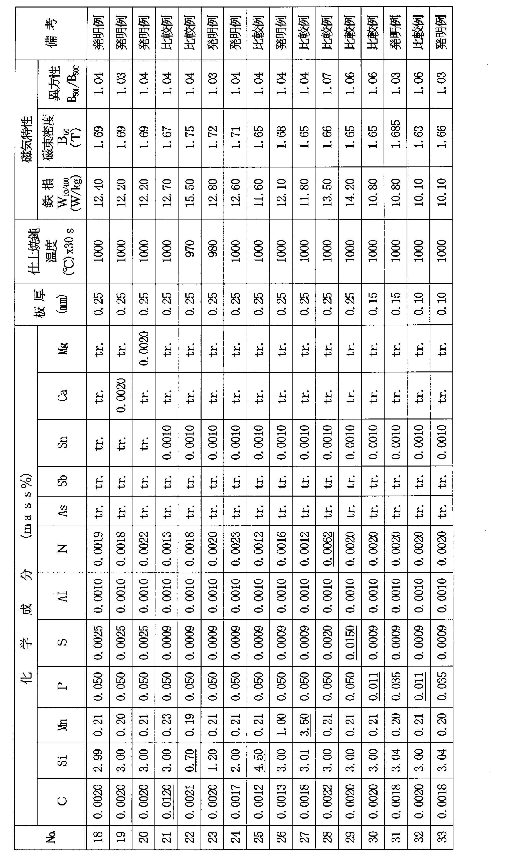
斯くして得た冷延焼鈍板から、幅30mm×長さ280mmのエプスタイン試験片を圧延方向(L方向)および圧延方向に直角方向(C方向)から切り出し、JIS C2550に準拠して、鉄損W10/400および磁束密度B50、異方性(B50L/B50C)をそれぞれ測定し、その結果を表1中に併記した。

Claims (5)
- C:0.01mass%以下、Si:1~4mass%、Mn:0.05~3mass%、P:0.03~0.2mass%、S:0.01mass%以下、Al:0.004mass%以下、N:0.005mass%以下およびAs:0.003mass%以下を含有し、残部がFeおよび不可避的不純物からなる成分組成を有する無方向性電磁鋼板。
- 上記成分組成に加えてさらに、Sb:0.001~0.1mass%およびSn:0.001~0.1mass%のうちから選ばれる1種または2種を含有することを特徴とする請求項1に記載の無方向性電磁鋼板。
- 上記成分組成に加えてさらに、Ca:0.001~0.005mass%およびMg:0.001~0.005mass%のうちから選ばれる1種または2種を含有することを特徴とする請求項1または2に記載の無方向性電磁鋼板。
- 圧延方向(L方向)の磁束密度B50Lと圧延方向に直角方向(C方向)の磁束密度B50Cの比(B50L/B50C)が1.05以下であることを特徴とする請求項1~3のいずれか1項に記載の無方向性電磁鋼板。
- 板厚が0.05~0.30mmであることを特徴とする請求項1~4のいずれか1項に記載の無方向性電磁鋼板。
Priority Applications (5)
| Application Number | Priority Date | Filing Date | Title |
|---|---|---|---|
| CN201480014256.6A CN105189799A (zh) | 2013-03-13 | 2014-03-11 | 磁特性优异的无取向电磁钢板 |
| RU2015143615A RU2617305C2 (ru) | 2013-03-13 | 2014-03-11 | Лист из нетекстурированной электротехнической стали с превосходными магнитными свойствами |
| US14/774,258 US10102951B2 (en) | 2013-03-13 | 2014-03-11 | Non-oriented electrical steel sheet having excellent magnetic properties |
| EP14765508.8A EP2975152B1 (en) | 2013-03-13 | 2014-03-11 | Non-oriented electrical steel sheet having excellent magnetic properties. |
| KR1020157024974A KR101797334B1 (ko) | 2013-03-13 | 2014-03-11 | 자기 특성이 우수한 무방향성 전기 강판 |
Applications Claiming Priority (4)
| Application Number | Priority Date | Filing Date | Title |
|---|---|---|---|
| JP2013049757 | 2013-03-13 | ||
| JP2013-049757 | 2013-03-13 | ||
| JP2013264050A JP6057082B2 (ja) | 2013-03-13 | 2013-12-20 | 磁気特性に優れる無方向性電磁鋼板 |
| JP2013-264050 | 2013-12-20 |
Publications (1)
| Publication Number | Publication Date |
|---|---|
| WO2014142100A1 true WO2014142100A1 (ja) | 2014-09-18 |
Family
ID=51536755
Family Applications (1)
| Application Number | Title | Priority Date | Filing Date |
|---|---|---|---|
| PCT/JP2014/056267 Ceased WO2014142100A1 (ja) | 2013-03-13 | 2014-03-11 | 磁気特性に優れる無方向性電磁鋼板 |
Country Status (8)
| Country | Link |
|---|---|
| US (1) | US10102951B2 (ja) |
| EP (1) | EP2975152B1 (ja) |
| JP (1) | JP6057082B2 (ja) |
| KR (1) | KR101797334B1 (ja) |
| CN (1) | CN105189799A (ja) |
| RU (1) | RU2617305C2 (ja) |
| TW (1) | TWI550102B (ja) |
| WO (1) | WO2014142100A1 (ja) |
Cited By (5)
| Publication number | Priority date | Publication date | Assignee | Title |
|---|---|---|---|---|
| WO2016136095A1 (ja) * | 2015-02-24 | 2016-09-01 | Jfeスチール株式会社 | 無方向性電磁鋼板の製造方法 |
| EP3260567A4 (en) * | 2015-02-18 | 2018-01-03 | JFE Steel Corporation | Non-oriented electrical steel sheet, production method therefor, and motor core |
| US10975451B2 (en) | 2015-08-04 | 2021-04-13 | Jfe Steel Corporation | Method for producing non-oriented electrical steel sheet having excellent magnetic properties |
| US11142813B2 (en) * | 2016-11-25 | 2021-10-12 | Jfe Steel Corporation | Non-oriented electrical steel sheet and manufacturing method therefor |
| US11649532B2 (en) | 2018-05-21 | 2023-05-16 | Jfe Steel Corporation | Non-oriented electrical steel sheet and method of producing same |
Families Citing this family (8)
| Publication number | Priority date | Publication date | Assignee | Title |
|---|---|---|---|---|
| EP3399061B1 (en) * | 2015-12-28 | 2020-06-17 | JFE Steel Corporation | Non-oriented electrical steel sheet and method for manufacturing non-oriented electrical steel sheet |
| JP6451967B2 (ja) * | 2016-01-15 | 2019-01-16 | Jfeスチール株式会社 | 無方向性電磁鋼板とその製造方法 |
| KR102003857B1 (ko) * | 2017-10-27 | 2019-10-17 | 주식회사 포스코 | 무방향성 전기강판 및 그 제조방법 |
| KR102380300B1 (ko) * | 2017-12-12 | 2022-03-29 | 제이에프이 스틸 가부시키가이샤 | 복층형 전기 강판 |
| KR102009392B1 (ko) | 2017-12-26 | 2019-08-09 | 주식회사 포스코 | 무방향성 전기강판 및 그 제조방법 |
| KR102105530B1 (ko) * | 2018-09-27 | 2020-04-28 | 주식회사 포스코 | 무방향성 전기강판 및 그 제조방법 |
| KR102134311B1 (ko) * | 2018-09-27 | 2020-07-15 | 주식회사 포스코 | 무방향성 전기강판 및 그 제조방법 |
| KR102278897B1 (ko) * | 2019-12-19 | 2021-07-16 | 주식회사 포스코 | 무방향성 전기강판 및 그 제조방법 |
Citations (9)
| Publication number | Priority date | Publication date | Assignee | Title |
|---|---|---|---|---|
| JPH06330260A (ja) * | 1993-05-26 | 1994-11-29 | Nkk Corp | 鉄損特性の優れた高周波用無方向性電磁鋼板 |
| JPH0860311A (ja) * | 1994-08-22 | 1996-03-05 | Nkk Corp | 鉄損の低い薄物無方向性電磁鋼板およびその製造方法 |
| JPH11310857A (ja) * | 1998-02-26 | 1999-11-09 | Sumitomo Metal Ind Ltd | 無方向性電磁鋼板およびその製造方法 |
| JP2000129410A (ja) | 1998-10-30 | 2000-05-09 | Nkk Corp | 磁束密度の高い無方向性電磁鋼板 |
| JP2001335897A (ja) * | 2000-05-24 | 2001-12-04 | Kawasaki Steel Corp | 加工性およびリサイクル性に優れた低鉄損かつ高磁束密度の無方向性電磁鋼板 |
| JP2004292829A (ja) * | 2003-02-06 | 2004-10-21 | Sumitomo Metal Ind Ltd | 無方向性電磁鋼板 |
| WO2005033349A1 (ja) * | 2003-10-06 | 2005-04-14 | Nippon Steel Corporation | 高強度電磁鋼板およびその加工部品とそれらの製造方法 |
| CN102634742A (zh) * | 2012-04-01 | 2012-08-15 | 首钢总公司 | 一种无Al的取向电工钢及其制备方法 |
| JP2014040622A (ja) * | 2012-08-21 | 2014-03-06 | Jfe Steel Corp | 打抜加工による鉄損劣化の小さい無方向性電磁鋼板 |
Family Cites Families (57)
| Publication number | Priority date | Publication date | Assignee | Title |
|---|---|---|---|---|
| JPH07116510B2 (ja) | 1990-01-23 | 1995-12-13 | 日本鋼管株式会社 | 無方向性電磁鋼板の製造方法 |
| JPH0819465B2 (ja) | 1990-02-02 | 1996-02-28 | 日本鋼管株式会社 | 無方向性電磁鋼板の製造方法 |
| JP2500033B2 (ja) | 1990-12-10 | 1996-05-29 | 川崎製鉄株式会社 | 磁気特性が優れかつ表面外観の良い無方向性電磁鋼板の製造方法 |
| JP2855994B2 (ja) | 1992-08-25 | 1999-02-10 | 日本鋼管株式会社 | 高周波磁気特性に優れた無方向性電磁鋼板 |
| JPH06108149A (ja) | 1992-09-29 | 1994-04-19 | Nippon Steel Corp | 需要家焼鈍後の鉄損が極めて優れた無方向性珪素鋼板の製造方法 |
| JP3333794B2 (ja) | 1994-09-29 | 2002-10-15 | 川崎製鉄株式会社 | 無方向性電磁鋼板の製造方法 |
| JP2970436B2 (ja) | 1994-11-11 | 1999-11-02 | 住友金属工業株式会社 | フルプロセス無方向性電磁鋼板の製造方法 |
| JPH08157966A (ja) | 1994-11-30 | 1996-06-18 | Nkk Corp | フルプロセス無方向性電磁鋼板の製造方法 |
| JP3348811B2 (ja) | 1995-10-30 | 2002-11-20 | 新日本製鐵株式会社 | 磁束密度が高く、鉄損の低い無方向性電磁鋼板の製造方法 |
| JP2718403B2 (ja) | 1995-11-13 | 1998-02-25 | 日本鋼管株式会社 | 磁性焼鈍後の鉄損の低い無方向性電磁鋼板 |
| KR100240995B1 (ko) | 1995-12-19 | 2000-03-02 | 이구택 | 절연피막의 밀착성이 우수한 무방향성 전기강판의 제조방법 |
| JPH09263908A (ja) | 1996-03-26 | 1997-10-07 | Sumitomo Metal Ind Ltd | 無方向性電磁鋼板およびその製造方法 |
| JP3378934B2 (ja) | 1996-08-19 | 2003-02-17 | 新日本製鐵株式会社 | 磁気特性と表面性状の優れた無方向性電磁鋼板の製造方法 |
| JPH10237606A (ja) | 1997-02-26 | 1998-09-08 | Nkk Corp | 磁性焼鈍後の鉄損の低い無方向性電磁鋼板 |
| JP2000096196A (ja) | 1998-09-25 | 2000-04-04 | Nippon Steel Corp | 鉄損の低い無方向性電磁鋼板及びその製造方法 |
| JP2000219917A (ja) * | 1999-01-28 | 2000-08-08 | Nippon Steel Corp | 磁束密度が高く鉄損の低い無方向性電磁鋼板の製造法 |
| JP2000219916A (ja) | 1999-01-28 | 2000-08-08 | Nippon Steel Corp | 磁束密度が高く鉄損の低い無方向性電磁鋼板の製造法 |
| JP2000273549A (ja) | 1999-03-25 | 2000-10-03 | Nkk Corp | 磁気特性の優れた無方向性電磁鋼板の製造方法 |
| JP2000328207A (ja) | 1999-05-18 | 2000-11-28 | Nkk Corp | 耐窒化・耐内部酸化性に優れた電磁鋼板 |
| JP4374095B2 (ja) | 1999-06-23 | 2009-12-02 | 新日本製鐵株式会社 | 無方向性電磁鋼板の製造方法 |
| JP2001131717A (ja) | 1999-11-05 | 2001-05-15 | Kawasaki Steel Corp | 打ち抜き性に優れた低鉄損無方向性電磁鋼板 |
| JP4019577B2 (ja) | 1999-12-01 | 2007-12-12 | Jfeスチール株式会社 | 電動パワーステアリングモータコア |
| JP2001192788A (ja) * | 2000-01-12 | 2001-07-17 | Sumitomo Metal Ind Ltd | 加工性の優れた無方向性電磁鋼板とその製造方法 |
| JP4126479B2 (ja) | 2000-04-28 | 2008-07-30 | Jfeスチール株式会社 | 無方向性電磁鋼板の製造方法 |
| JP4258951B2 (ja) | 2000-05-15 | 2009-04-30 | Jfeスチール株式会社 | 無方向性電磁鋼板 |
| JP2001323344A (ja) | 2000-05-15 | 2001-11-22 | Kawasaki Steel Corp | 加工性およびリサイクル性に優れた無方向性電磁鋼板 |
| JP2002030397A (ja) | 2000-07-13 | 2002-01-31 | Sumitomo Metal Ind Ltd | 無方向性電磁鋼板とその製造方法 |
| JP3835137B2 (ja) | 2000-07-28 | 2006-10-18 | 住友金属工業株式会社 | 無方向性電磁鋼板およびその製造方法 |
| WO2003002777A1 (fr) | 2001-06-28 | 2003-01-09 | Jfe Steel Corporation | Feuille en acier electromagnetique non orientee |
| JP3835216B2 (ja) | 2001-08-09 | 2006-10-18 | 住友金属工業株式会社 | 無方向性電磁鋼板およびその製造方法 |
| CN100475982C (zh) | 2002-05-08 | 2009-04-08 | Ak钢铁资产公司 | 非取向电工钢带的连铸方法 |
| JP4718749B2 (ja) | 2002-08-06 | 2011-07-06 | Jfeスチール株式会社 | 回転機用高磁束密度無方向性電磁鋼板及び回転機用部材 |
| JP3870893B2 (ja) | 2002-11-29 | 2007-01-24 | 住友金属工業株式会社 | 無方向性電磁鋼板およびその製造方法 |
| JP2005200756A (ja) | 2004-01-19 | 2005-07-28 | Sumitomo Metal Ind Ltd | 無方向性電磁鋼板の製造方法 |
| JP4833523B2 (ja) | 2004-02-17 | 2011-12-07 | 新日本製鐵株式会社 | 電磁鋼板とその製造方法 |
| JP4701669B2 (ja) | 2004-10-06 | 2011-06-15 | Jfeスチール株式会社 | 無方向性電磁鋼板の製造方法 |
| JP4568190B2 (ja) | 2004-09-22 | 2010-10-27 | 新日本製鐵株式会社 | 無方向性電磁鋼板 |
| JP4804478B2 (ja) | 2004-12-21 | 2011-11-02 | ポスコ | 磁束密度を向上させた無方向性電磁鋼板の製造方法 |
| WO2007007423A1 (ja) * | 2005-07-07 | 2007-01-18 | Sumitomo Metal Industries, Ltd. | 無方向性電磁鋼板およびその製造方法 |
| JP4779474B2 (ja) * | 2005-07-07 | 2011-09-28 | 住友金属工業株式会社 | 回転子用無方向性電磁鋼板およびその製造方法 |
| JP4979904B2 (ja) | 2005-07-28 | 2012-07-18 | 新日本製鐵株式会社 | 電磁鋼板の製造方法 |
| JP5009514B2 (ja) | 2005-08-10 | 2012-08-22 | Jfeスチール株式会社 | 無方向性電磁鋼板 |
| JP4658840B2 (ja) | 2006-03-20 | 2011-03-23 | 新日本製鐵株式会社 | 無方向性電磁鋼板の製造方法 |
| RU2398894C1 (ru) | 2006-06-16 | 2010-09-10 | Ниппон Стил Корпорейшн | Лист высокопрочной электротехнической стали и способ его производства |
| JPWO2007144964A1 (ja) | 2006-06-16 | 2009-10-29 | 新日本製鐵株式会社 | 高強度電磁鋼板およびその製造方法 |
| JP5200376B2 (ja) | 2006-12-26 | 2013-06-05 | Jfeスチール株式会社 | 無方向性電磁鋼板およびその製造方法 |
| JP5417689B2 (ja) | 2007-03-20 | 2014-02-19 | Jfeスチール株式会社 | 無方向性電磁鋼板 |
| JP5609003B2 (ja) | 2009-04-14 | 2014-10-22 | 新日鐵住金株式会社 | 無方向性電磁鋼板 |
| JP4681689B2 (ja) | 2009-06-03 | 2011-05-11 | 新日本製鐵株式会社 | 無方向性電磁鋼板及びその製造方法 |
| JP5338750B2 (ja) | 2010-06-09 | 2013-11-13 | Jfeスチール株式会社 | 無方向性電磁鋼板の製造方法 |
| JP5402846B2 (ja) | 2010-06-17 | 2014-01-29 | 新日鐵住金株式会社 | 無方向性電磁鋼板の製造方法 |
| JP5601078B2 (ja) | 2010-08-09 | 2014-10-08 | 新日鐵住金株式会社 | 無方向性電磁鋼板およびその製造方法 |
| JP5668460B2 (ja) | 2010-12-22 | 2015-02-12 | Jfeスチール株式会社 | 無方向性電磁鋼板の製造方法 |
| JP5699601B2 (ja) | 2010-12-28 | 2015-04-15 | Jfeスチール株式会社 | 無方向性電磁鋼板およびその製造方法 |
| JP5733409B2 (ja) | 2011-09-27 | 2015-06-10 | Jfeスチール株式会社 | 無方向性電磁鋼板 |
| JP5892327B2 (ja) | 2012-03-15 | 2016-03-23 | Jfeスチール株式会社 | 無方向性電磁鋼板の製造方法 |
| JP6127408B2 (ja) | 2012-08-17 | 2017-05-17 | Jfeスチール株式会社 | 無方向性電磁鋼板の製造方法 |
-
2013
- 2013-12-20 JP JP2013264050A patent/JP6057082B2/ja active Active
-
2014
- 2014-03-11 KR KR1020157024974A patent/KR101797334B1/ko active Active
- 2014-03-11 CN CN201480014256.6A patent/CN105189799A/zh active Pending
- 2014-03-11 US US14/774,258 patent/US10102951B2/en active Active
- 2014-03-11 WO PCT/JP2014/056267 patent/WO2014142100A1/ja not_active Ceased
- 2014-03-11 EP EP14765508.8A patent/EP2975152B1/en active Active
- 2014-03-11 RU RU2015143615A patent/RU2617305C2/ru active
- 2014-03-13 TW TW103109021A patent/TWI550102B/zh active
Patent Citations (9)
| Publication number | Priority date | Publication date | Assignee | Title |
|---|---|---|---|---|
| JPH06330260A (ja) * | 1993-05-26 | 1994-11-29 | Nkk Corp | 鉄損特性の優れた高周波用無方向性電磁鋼板 |
| JPH0860311A (ja) * | 1994-08-22 | 1996-03-05 | Nkk Corp | 鉄損の低い薄物無方向性電磁鋼板およびその製造方法 |
| JPH11310857A (ja) * | 1998-02-26 | 1999-11-09 | Sumitomo Metal Ind Ltd | 無方向性電磁鋼板およびその製造方法 |
| JP2000129410A (ja) | 1998-10-30 | 2000-05-09 | Nkk Corp | 磁束密度の高い無方向性電磁鋼板 |
| JP2001335897A (ja) * | 2000-05-24 | 2001-12-04 | Kawasaki Steel Corp | 加工性およびリサイクル性に優れた低鉄損かつ高磁束密度の無方向性電磁鋼板 |
| JP2004292829A (ja) * | 2003-02-06 | 2004-10-21 | Sumitomo Metal Ind Ltd | 無方向性電磁鋼板 |
| WO2005033349A1 (ja) * | 2003-10-06 | 2005-04-14 | Nippon Steel Corporation | 高強度電磁鋼板およびその加工部品とそれらの製造方法 |
| CN102634742A (zh) * | 2012-04-01 | 2012-08-15 | 首钢总公司 | 一种无Al的取向电工钢及其制备方法 |
| JP2014040622A (ja) * | 2012-08-21 | 2014-03-06 | Jfe Steel Corp | 打抜加工による鉄損劣化の小さい無方向性電磁鋼板 |
Non-Patent Citations (1)
| Title |
|---|
| See also references of EP2975152A4 |
Cited By (10)
| Publication number | Priority date | Publication date | Assignee | Title |
|---|---|---|---|---|
| EP3260567A4 (en) * | 2015-02-18 | 2018-01-03 | JFE Steel Corporation | Non-oriented electrical steel sheet, production method therefor, and motor core |
| US10941458B2 (en) | 2015-02-18 | 2021-03-09 | Jfe Steel Corporation | Non-oriented electrical steel sheet, production method therefor, and motor core |
| WO2016136095A1 (ja) * | 2015-02-24 | 2016-09-01 | Jfeスチール株式会社 | 無方向性電磁鋼板の製造方法 |
| JPWO2016136095A1 (ja) * | 2015-02-24 | 2017-04-27 | Jfeスチール株式会社 | 無方向性電磁鋼板の製造方法 |
| CN107208171A (zh) * | 2015-02-24 | 2017-09-26 | 杰富意钢铁株式会社 | 无取向性电磁钢板的制造方法 |
| US10316382B2 (en) | 2015-02-24 | 2019-06-11 | Jfe Steel Corporation | Method for producing non-oriented electrical steel sheets |
| US10975451B2 (en) | 2015-08-04 | 2021-04-13 | Jfe Steel Corporation | Method for producing non-oriented electrical steel sheet having excellent magnetic properties |
| US11142813B2 (en) * | 2016-11-25 | 2021-10-12 | Jfe Steel Corporation | Non-oriented electrical steel sheet and manufacturing method therefor |
| US11649532B2 (en) | 2018-05-21 | 2023-05-16 | Jfe Steel Corporation | Non-oriented electrical steel sheet and method of producing same |
| US11946123B2 (en) | 2018-05-21 | 2024-04-02 | Jfe Steel Corporation | Method of producing a non-oriented electrical steel sheet |
Also Published As
| Publication number | Publication date |
|---|---|
| KR20150119229A (ko) | 2015-10-23 |
| RU2617305C2 (ru) | 2017-04-24 |
| JP6057082B2 (ja) | 2017-01-11 |
| US10102951B2 (en) | 2018-10-16 |
| US20160042850A1 (en) | 2016-02-11 |
| CN105189799A (zh) | 2015-12-23 |
| TWI550102B (zh) | 2016-09-21 |
| EP2975152A1 (en) | 2016-01-20 |
| EP2975152A4 (en) | 2016-04-06 |
| RU2015143615A (ru) | 2017-04-19 |
| TW201443246A (zh) | 2014-11-16 |
| KR101797334B1 (ko) | 2017-11-13 |
| EP2975152B1 (en) | 2019-09-25 |
| JP2014198896A (ja) | 2014-10-23 |
Similar Documents
| Publication | Publication Date | Title |
|---|---|---|
| JP6057082B2 (ja) | 磁気特性に優れる無方向性電磁鋼板 | |
| JP5668460B2 (ja) | 無方向性電磁鋼板の製造方法 | |
| JP5854182B2 (ja) | 無方向性電磁鋼板の製造方法 | |
| JP6451873B2 (ja) | 無方向性電磁鋼板およびその製造方法 | |
| JP6319465B2 (ja) | 無方向性電磁鋼板およびその製造方法 | |
| JP6665794B2 (ja) | 無方向性電磁鋼板およびその製造方法 | |
| JP5825494B2 (ja) | 無方向性電磁鋼板およびその製造方法 | |
| TWI532854B (zh) | 磁特性優良的無方向性電磁鋼板 | |
| WO2013046661A1 (ja) | 無方向性電磁鋼板 | |
| WO2015199211A1 (ja) | 電磁鋼板 | |
| JP6319574B2 (ja) | 磁気特性に優れる無方向性電磁鋼板 | |
| WO2013080891A1 (ja) | 無方向性電磁鋼板の製造方法 | |
| JP5515451B2 (ja) | 分割モータ用コア材料 | |
| WO2014142149A1 (ja) | 高周波鉄損特性に優れる無方向性電磁鋼板 | |
| KR102510146B1 (ko) | 무방향성 전기 강판의 제조 방법 | |
| CN104302801A (zh) | 冲裁加工导致的铁损特性劣化较小的无方向性电磁钢板 |
Legal Events
| Date | Code | Title | Description |
|---|---|---|---|
| WWE | Wipo information: entry into national phase |
Ref document number: 201480014256.6 Country of ref document: CN |
|
| 121 | Ep: the epo has been informed by wipo that ep was designated in this application |
Ref document number: 14765508 Country of ref document: EP Kind code of ref document: A1 |
|
| WWE | Wipo information: entry into national phase |
Ref document number: 2014765508 Country of ref document: EP |
|
| WWE | Wipo information: entry into national phase |
Ref document number: 14774258 Country of ref document: US |
|
| ENP | Entry into the national phase |
Ref document number: 20157024974 Country of ref document: KR Kind code of ref document: A |
|
| NENP | Non-entry into the national phase |
Ref country code: DE |
|
| ENP | Entry into the national phase |
Ref document number: 2015143615 Country of ref document: RU Kind code of ref document: A |