WO2014142210A1 - Dispositif de commande de véhicule et motocycle équipé de celui-ci - Google Patents
Dispositif de commande de véhicule et motocycle équipé de celui-ci Download PDFInfo
- Publication number
- WO2014142210A1 WO2014142210A1 PCT/JP2014/056583 JP2014056583W WO2014142210A1 WO 2014142210 A1 WO2014142210 A1 WO 2014142210A1 JP 2014056583 W JP2014056583 W JP 2014056583W WO 2014142210 A1 WO2014142210 A1 WO 2014142210A1
- Authority
- WO
- WIPO (PCT)
- Prior art keywords
- target
- engine
- rotation speed
- speed
- engine rotation
- Prior art date
- Legal status (The legal status is an assumption and is not a legal conclusion. Google has not performed a legal analysis and makes no representation as to the accuracy of the status listed.)
- Ceased
Links
Images




Classifications
-
- B—PERFORMING OPERATIONS; TRANSPORTING
- B60—VEHICLES IN GENERAL
- B60W—CONJOINT CONTROL OF VEHICLE SUB-UNITS OF DIFFERENT TYPE OR DIFFERENT FUNCTION; CONTROL SYSTEMS SPECIALLY ADAPTED FOR HYBRID VEHICLES; ROAD VEHICLE DRIVE CONTROL SYSTEMS FOR PURPOSES NOT RELATED TO THE CONTROL OF A PARTICULAR SUB-UNIT
- B60W10/00—Conjoint control of vehicle sub-units of different type or different function
- B60W10/04—Conjoint control of vehicle sub-units of different type or different function including control of propulsion units
- B60W10/06—Conjoint control of vehicle sub-units of different type or different function including control of propulsion units including control of combustion engines
-
- B—PERFORMING OPERATIONS; TRANSPORTING
- B60—VEHICLES IN GENERAL
- B60W—CONJOINT CONTROL OF VEHICLE SUB-UNITS OF DIFFERENT TYPE OR DIFFERENT FUNCTION; CONTROL SYSTEMS SPECIALLY ADAPTED FOR HYBRID VEHICLES; ROAD VEHICLE DRIVE CONTROL SYSTEMS FOR PURPOSES NOT RELATED TO THE CONTROL OF A PARTICULAR SUB-UNIT
- B60W10/00—Conjoint control of vehicle sub-units of different type or different function
- B60W10/10—Conjoint control of vehicle sub-units of different type or different function including control of change-speed gearings
- B60W10/101—Infinitely variable gearings
- B60W10/107—Infinitely variable gearings with endless flexible members
-
- B—PERFORMING OPERATIONS; TRANSPORTING
- B60—VEHICLES IN GENERAL
- B60W—CONJOINT CONTROL OF VEHICLE SUB-UNITS OF DIFFERENT TYPE OR DIFFERENT FUNCTION; CONTROL SYSTEMS SPECIALLY ADAPTED FOR HYBRID VEHICLES; ROAD VEHICLE DRIVE CONTROL SYSTEMS FOR PURPOSES NOT RELATED TO THE CONTROL OF A PARTICULAR SUB-UNIT
- B60W30/00—Purposes of road vehicle drive control systems not related to the control of a particular sub-unit, e.g. of systems using conjoint control of vehicle sub-units
- B60W30/18—Propelling the vehicle
- B60W30/188—Controlling power parameters of the driveline, e.g. determining the required power
- B60W30/1882—Controlling power parameters of the driveline, e.g. determining the required power characterised by the working point of the engine, e.g. by using engine output chart
-
- B—PERFORMING OPERATIONS; TRANSPORTING
- B60—VEHICLES IN GENERAL
- B60W—CONJOINT CONTROL OF VEHICLE SUB-UNITS OF DIFFERENT TYPE OR DIFFERENT FUNCTION; CONTROL SYSTEMS SPECIALLY ADAPTED FOR HYBRID VEHICLES; ROAD VEHICLE DRIVE CONTROL SYSTEMS FOR PURPOSES NOT RELATED TO THE CONTROL OF A PARTICULAR SUB-UNIT
- B60W30/00—Purposes of road vehicle drive control systems not related to the control of a particular sub-unit, e.g. of systems using conjoint control of vehicle sub-units
- B60W30/18—Propelling the vehicle
- B60W30/19—Improvement of gear change, e.g. by synchronisation or smoothing gear shift
-
- F—MECHANICAL ENGINEERING; LIGHTING; HEATING; WEAPONS; BLASTING
- F02—COMBUSTION ENGINES; HOT-GAS OR COMBUSTION-PRODUCT ENGINE PLANTS
- F02D—CONTROLLING COMBUSTION ENGINES
- F02D11/00—Arrangements for, or adaptations to, non-automatic engine control initiation means, e.g. operator initiated
- F02D11/06—Arrangements for, or adaptations to, non-automatic engine control initiation means, e.g. operator initiated characterised by non-mechanical control linkages, e.g. fluid control linkages or by control linkages with power drive or assistance
- F02D11/10—Arrangements for, or adaptations to, non-automatic engine control initiation means, e.g. operator initiated characterised by non-mechanical control linkages, e.g. fluid control linkages or by control linkages with power drive or assistance of the electric type
- F02D11/105—Arrangements for, or adaptations to, non-automatic engine control initiation means, e.g. operator initiated characterised by non-mechanical control linkages, e.g. fluid control linkages or by control linkages with power drive or assistance of the electric type characterised by the function converting demand to actuation, e.g. a map indicating relations between an accelerator pedal position and throttle valve opening or target engine torque
-
- F—MECHANICAL ENGINEERING; LIGHTING; HEATING; WEAPONS; BLASTING
- F02—COMBUSTION ENGINES; HOT-GAS OR COMBUSTION-PRODUCT ENGINE PLANTS
- F02D—CONTROLLING COMBUSTION ENGINES
- F02D41/00—Electrical control of supply of combustible mixture or its constituents
- F02D41/02—Circuit arrangements for generating control signals
- F02D41/0205—Circuit arrangements for generating control signals using an auxiliary engine speed control
-
- F—MECHANICAL ENGINEERING; LIGHTING; HEATING; WEAPONS; BLASTING
- F02—COMBUSTION ENGINES; HOT-GAS OR COMBUSTION-PRODUCT ENGINE PLANTS
- F02D—CONTROLLING COMBUSTION ENGINES
- F02D41/00—Electrical control of supply of combustible mixture or its constituents
- F02D41/02—Circuit arrangements for generating control signals
- F02D41/021—Introducing corrections for particular conditions exterior to the engine
- F02D41/0215—Introducing corrections for particular conditions exterior to the engine in relation with elements of the transmission
- F02D41/0225—Introducing corrections for particular conditions exterior to the engine in relation with elements of the transmission in relation with the gear ratio or shift lever position
-
- F—MECHANICAL ENGINEERING; LIGHTING; HEATING; WEAPONS; BLASTING
- F16—ENGINEERING ELEMENTS AND UNITS; GENERAL MEASURES FOR PRODUCING AND MAINTAINING EFFECTIVE FUNCTIONING OF MACHINES OR INSTALLATIONS; THERMAL INSULATION IN GENERAL
- F16H—GEARING
- F16H61/00—Control functions within control units of change-speed- or reversing-gearings for conveying rotary motion ; Control of exclusively fluid gearing, friction gearing, gearings with endless flexible members or other particular types of gearing
- F16H61/66—Control functions within control units of change-speed- or reversing-gearings for conveying rotary motion ; Control of exclusively fluid gearing, friction gearing, gearings with endless flexible members or other particular types of gearing specially adapted for continuously variable gearings
- F16H61/662—Control functions within control units of change-speed- or reversing-gearings for conveying rotary motion ; Control of exclusively fluid gearing, friction gearing, gearings with endless flexible members or other particular types of gearing specially adapted for continuously variable gearings with endless flexible members
- F16H61/66254—Control functions within control units of change-speed- or reversing-gearings for conveying rotary motion ; Control of exclusively fluid gearing, friction gearing, gearings with endless flexible members or other particular types of gearing specially adapted for continuously variable gearings with endless flexible members controlling of shifting being influenced by a signal derived from the engine and the main coupling
- F16H61/66259—Control functions within control units of change-speed- or reversing-gearings for conveying rotary motion ; Control of exclusively fluid gearing, friction gearing, gearings with endless flexible members or other particular types of gearing specially adapted for continuously variable gearings with endless flexible members controlling of shifting being influenced by a signal derived from the engine and the main coupling using electrical or electronical sensing or control means
-
- B—PERFORMING OPERATIONS; TRANSPORTING
- B60—VEHICLES IN GENERAL
- B60W—CONJOINT CONTROL OF VEHICLE SUB-UNITS OF DIFFERENT TYPE OR DIFFERENT FUNCTION; CONTROL SYSTEMS SPECIALLY ADAPTED FOR HYBRID VEHICLES; ROAD VEHICLE DRIVE CONTROL SYSTEMS FOR PURPOSES NOT RELATED TO THE CONTROL OF A PARTICULAR SUB-UNIT
- B60W2520/00—Input parameters relating to overall vehicle dynamics
- B60W2520/10—Longitudinal speed
-
- B—PERFORMING OPERATIONS; TRANSPORTING
- B60—VEHICLES IN GENERAL
- B60W—CONJOINT CONTROL OF VEHICLE SUB-UNITS OF DIFFERENT TYPE OR DIFFERENT FUNCTION; CONTROL SYSTEMS SPECIALLY ADAPTED FOR HYBRID VEHICLES; ROAD VEHICLE DRIVE CONTROL SYSTEMS FOR PURPOSES NOT RELATED TO THE CONTROL OF A PARTICULAR SUB-UNIT
- B60W2540/00—Input parameters relating to occupants
- B60W2540/10—Accelerator pedal position
-
- B—PERFORMING OPERATIONS; TRANSPORTING
- B60—VEHICLES IN GENERAL
- B60W—CONJOINT CONTROL OF VEHICLE SUB-UNITS OF DIFFERENT TYPE OR DIFFERENT FUNCTION; CONTROL SYSTEMS SPECIALLY ADAPTED FOR HYBRID VEHICLES; ROAD VEHICLE DRIVE CONTROL SYSTEMS FOR PURPOSES NOT RELATED TO THE CONTROL OF A PARTICULAR SUB-UNIT
- B60W2540/00—Input parameters relating to occupants
- B60W2540/30—Driving style
-
- B—PERFORMING OPERATIONS; TRANSPORTING
- B60—VEHICLES IN GENERAL
- B60W—CONJOINT CONTROL OF VEHICLE SUB-UNITS OF DIFFERENT TYPE OR DIFFERENT FUNCTION; CONTROL SYSTEMS SPECIALLY ADAPTED FOR HYBRID VEHICLES; ROAD VEHICLE DRIVE CONTROL SYSTEMS FOR PURPOSES NOT RELATED TO THE CONTROL OF A PARTICULAR SUB-UNIT
- B60W2710/00—Output or target parameters relating to a particular sub-units
- B60W2710/06—Combustion engines, Gas turbines
- B60W2710/0605—Throttle position
-
- B—PERFORMING OPERATIONS; TRANSPORTING
- B60—VEHICLES IN GENERAL
- B60W—CONJOINT CONTROL OF VEHICLE SUB-UNITS OF DIFFERENT TYPE OR DIFFERENT FUNCTION; CONTROL SYSTEMS SPECIALLY ADAPTED FOR HYBRID VEHICLES; ROAD VEHICLE DRIVE CONTROL SYSTEMS FOR PURPOSES NOT RELATED TO THE CONTROL OF A PARTICULAR SUB-UNIT
- B60W2710/00—Output or target parameters relating to a particular sub-units
- B60W2710/06—Combustion engines, Gas turbines
- B60W2710/0644—Engine speed
-
- B—PERFORMING OPERATIONS; TRANSPORTING
- B60—VEHICLES IN GENERAL
- B60W—CONJOINT CONTROL OF VEHICLE SUB-UNITS OF DIFFERENT TYPE OR DIFFERENT FUNCTION; CONTROL SYSTEMS SPECIALLY ADAPTED FOR HYBRID VEHICLES; ROAD VEHICLE DRIVE CONTROL SYSTEMS FOR PURPOSES NOT RELATED TO THE CONTROL OF A PARTICULAR SUB-UNIT
- B60W2710/00—Output or target parameters relating to a particular sub-units
- B60W2710/10—Change speed gearings
- B60W2710/1005—Transmission ratio engaged
-
- B—PERFORMING OPERATIONS; TRANSPORTING
- B60—VEHICLES IN GENERAL
- B60Y—INDEXING SCHEME RELATING TO ASPECTS CROSS-CUTTING VEHICLE TECHNOLOGY
- B60Y2200/00—Type of vehicle
- B60Y2200/10—Road Vehicles
- B60Y2200/12—Motorcycles, Trikes; Quads; Scooters
- B60Y2200/126—Scooters
-
- F—MECHANICAL ENGINEERING; LIGHTING; HEATING; WEAPONS; BLASTING
- F02—COMBUSTION ENGINES; HOT-GAS OR COMBUSTION-PRODUCT ENGINE PLANTS
- F02D—CONTROLLING COMBUSTION ENGINES
- F02D2400/00—Control systems adapted for specific engine types; Special features of engine control systems not otherwise provided for; Power supply, connectors or cabling for engine control systems
- F02D2400/12—Engine control specially adapted for a transmission comprising a torque converter or for continuously variable transmissions
-
- F—MECHANICAL ENGINEERING; LIGHTING; HEATING; WEAPONS; BLASTING
- F16—ENGINEERING ELEMENTS AND UNITS; GENERAL MEASURES FOR PRODUCING AND MAINTAINING EFFECTIVE FUNCTIONING OF MACHINES OR INSTALLATIONS; THERMAL INSULATION IN GENERAL
- F16H—GEARING
- F16H61/00—Control functions within control units of change-speed- or reversing-gearings for conveying rotary motion ; Control of exclusively fluid gearing, friction gearing, gearings with endless flexible members or other particular types of gearing
- F16H61/66—Control functions within control units of change-speed- or reversing-gearings for conveying rotary motion ; Control of exclusively fluid gearing, friction gearing, gearings with endless flexible members or other particular types of gearing specially adapted for continuously variable gearings
- F16H2061/6604—Special control features generally applicable to continuously variable gearings
- F16H2061/6611—Control to achieve a particular driver perception, e.g. for generating a shift shock sensation
Definitions
- the present invention relates to a vehicle control device that electronically controls both the opening of a throttle valve that adjusts the amount of air supplied to an engine and the transmission of a continuously variable transmission.
- a vehicle control device that electronically controls a gear ratio of a continuously variable transmission and an opening of a throttle valve (hereinafter, throttle opening) using an actuator (for example, Japanese Patent No. 3754188).
- throttle opening a throttle valve
- the required driving force is calculated based on the amount of accelerator operation (accelerator operation amount) by the driver and the vehicle speed.
- the target engine speed and the throttle opening are calculated so that this required driving force can be obtained.
- the engine speed has a greater influence on the feeling of riding than in a four-wheeled vehicle, so there is a strong demand to set the engine speed to a speed that provides a comfortable riding feeling.
- the required driving force is calculated, and then the target engine speed is calculated so that the required driving force can be obtained.
- the target engine speed is affected by the required driving force, it may be difficult to control the engine speed so as to obtain a comfortable ride feeling.
- One of the objects of the present invention is a vehicle control device that electronically controls the transmission gear ratio and throttle opening of a continuously variable transmission, and can provide a comfortable ride feeling and is adapted to the driving intention of the driver. It is an object of the present invention to provide a control device capable of realizing a rotational speed and a motorcycle including the same.
- the control device electronically controls the gear ratio of the continuously variable transmission and the throttle opening using an actuator.
- the control device previously stores first basic information that defines an engine rotational speed in the first operation mode of the vehicle and second basic information that defines an engine rotational speed in the second operation mode of the vehicle.
- a stored storage device a first basic engine rotational speed calculation unit that calculates an engine rotational speed obtained from the first basic information as a first engine rotational speed; and an engine obtained from the second basic information.
- a second basic engine rotation speed calculation unit that calculates a rotation speed as a second engine rotation speed; a driving intention acquisition unit that acquires a driving intention value that is a numerical value representing the driving intention of the driver; and the first engine.
- a target engine speed calculation for calculating a target engine speed based on the engine speed calculated between the rotation speed and the second engine speed and corresponding to the driving intention value.
- a target speed ratio calculation unit that calculates the target speed ratio of the continuously variable transmission based on the target engine speed, the accelerator operation amount detected by the sensor, and the target engine speed
- a target driving force calculation unit that calculates a target value related to the driving force of the vehicle, and a target throttle opening degree is calculated based on the target value and the target engine speed so as to obtain a driving force corresponding to the target value.
- a target throttle opening degree calculation unit A motorcycle according to the present invention includes the control device.
- the target engine rotation speed is first calculated, and then the target value related to the driving force is calculated. Therefore, it is possible to suppress the target value relating to the driving force of the vehicle from affecting the setting of the target engine speed. As a result, it becomes easy to control the engine speed so that a comfortable riding feeling can be obtained.
- the driving intention value is used to calculate the target engine rotation speed, an engine rotation speed suitable for the driver's driving intention can be realized.
- the engine rotation speed defined by the second basic information is a rotation speed that can realize better acceleration response than the engine rotation speed defined by the first basic information.
- the target engine rotational speed is set to a rotational speed close to the second engine rotational speed obtained from the second basic information.
- the target engine rotation speed may be the same as the engine rotation speed corresponding to the driving intention value, or may be the engine rotation speed obtained by correcting the engine rotation speed corresponding to the driving intention value.
- the target value related to the driving force of the vehicle is, for example, a target value for driving wheel torque or driving wheel output. Further, the target value related to the driving force of the vehicle may be a target value for engine torque, a target value for engine output, a target value for vehicle acceleration, etc. (the product of vehicle acceleration and vehicle weight is the vehicle drive Power).
- the driving intention acquisition unit may calculate the driving intention value based on a driving state of the vehicle. According to this, the driving intention value can be acquired without being operated by the driver.
- the target engine rotation speed unit may correct the engine rotation speed according to the driving intention value, and calculate the corrected engine rotation speed as the target engine rotation speed. According to this, traveling with good fuel consumption can be realized, for example, by reducing the target engine speed by correction.
- the first basic information associates the accelerator operation amount with the engine rotation speed in the first operation mode
- the second basic information associates the accelerator operation amount with the engine rotation speed in the second operation mode.
- the first basic engine rotation speed calculation unit may calculate the first engine rotation speed based on an accelerator operation amount detected by the sensor with reference to the first basic information
- the second basic engine rotation speed calculation unit may calculate the second engine rotation speed from the accelerator operation amount detected by the sensor with reference to the second basic information.
- the driving intention acquisition unit may limit a change in the driving intention value when the vehicle is in a predetermined traveling state.
- the predetermined traveling state is a traveling state estimated that the acceleration request by the driver is increased
- the driving intention acquisition unit is configured to perform the driving in the traveling state estimated that the acceleration request by the driver is increased.
- the change in the driving intention value may be limited so that the change in the direction in which the engine rotation speed decreases according to the intention value is suppressed. According to this, it is possible to suppress a decrease in acceleration responsiveness due to a change in the driving intention value in a driving situation in which the acceleration request is estimated to increase.
- the predetermined traveling situation is, for example, a case where the vehicle is traveling on a curve, a case where a brake device is operating, or a case where the vehicle is traveling on an uphill.
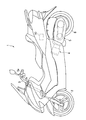
- 1 is a side view of a motorcycle including a control device according to an embodiment of the present invention.
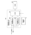
- 1 is a block diagram showing a configuration of a motorcycle. It is a block diagram which shows the process of a control apparatus. It is a block diagram which shows the process of a reference
- (A) is an example of a first engine speed map (first basic information), and (b) is an example of a second engine speed map (second basic information).
- A is an example of a first engine speed map (first basic information)
- (b) is an example of a second engine speed map (second basic information).
- A is an example of a first engine speed map (first basic information)
- (b) is an example of a second engine speed map (second basic information).
- FIG. 1 is a side view of a motorcycle 1 including a control device 10 according to an embodiment of the present invention.
- FIG. 2 is a block diagram showing the configuration of the motorcycle 1.
- the motorcycle 1 has a front wheel 2 and a rear wheel 8.
- the front wheel 2 is provided with a front wheel rotational speed sensor 28 (see FIG. 2) that outputs a signal corresponding to the rotational speed of the front wheel 2, and the rear wheel 8 is a rear wheel that outputs a signal corresponding to the rotational speed of the rear wheel 8.
- a rotation speed sensor 27 (see FIG. 2) is provided.
- the control device 10 calculates the vehicle speed based on the output of the front wheel rotational speed sensor 28 or the rear wheel rotational speed sensor 27.
- the motorcycle 1 has a steering 3 for steering the front wheel 2.
- Grips 3 a are provided on the left and right of the steering 3.
- One grip 3a functions as an accelerator grip, and an accelerator sensor 24 (see FIG.
- the front wheel 2 and the rear wheel 8 are provided with a brake device for braking them, and the steering 3 is provided with a brake lever 3b for operating the brake device.
- the brake lever 3b is provided with a brake switch 29 (see FIG. 2) for detecting the operation.
- the motorcycle 1 has a continuously variable transmission (hereinafter referred to as CVT) 5, a clutch 6, a final reduction mechanism 7, and a torque transmission path from the engine 4 to the rear wheel 8 that is a driving wheel.
- CVT continuously variable transmission
- the clutch 6 is disposed downstream of the CVT 5.
- a final reduction mechanism 7 is disposed between the clutch 6 and the rear wheel 8.
- the clutch 6 is an automatic clutch such as a centrifugal clutch.
- the engine 4 has a cylinder, a piston disposed in the cylinder, a crankshaft connected to the piston, and the like.
- the motorcycle 1 has an engine rotation speed sensor 21 for detecting the engine rotation speed.
- the engine 4 also has a throttle valve that controls the amount of air supplied to the engine 4 and an injector that supplies fuel to the engine 4 in an intake passage connected to the combustion chamber.
- the motorcycle 1 has a throttle opening sensor 22 for detecting the opening of the throttle valve (hereinafter referred to as throttle opening) and a throttle actuator 23 for controlling the throttle valve.
- the CVT 5 is stretched over an input shaft interlocked with the crankshaft, a driving pulley disposed on the input shaft, an output shaft, a driven pulley disposed on the output shaft, a driving pulley and a driven pulley. And a belt for transmitting the rotation (torque) of the driving pulley to the driven pulley.
- the motorcycle 1 has a CVT actuator 25 for controlling the transmission ratio of the CVT 5.
- the CVT actuator 25 controls one of the two sheaves constituting the drive pulley to control the gear ratio.
- the CVT actuator 25 may control the gear ratio by moving one of the two sheaves constituting the driven pulley.
- the CVT 5 is provided with an output shaft rotational speed sensor 26 for detecting the rotational speed of the output shaft of the CVT 5.
- the control device 10 includes a storage device 10c and a microprocessor that executes a program stored in the storage device 10c.
- a map used for controlling the engine 4 and the CVT 5 is stored in the storage device 10c.
- the control device 10 may include a microprocessor mainly responsible for controlling the engine 4 and a microprocessor mainly responsible for controlling the CVT 5.
- the two microprocessors communicate according to a predetermined protocol, and transmit / receive information calculated by each other.
- Output signals from the sensors 21, 22, 24, 26, 27, 28, and 29 are input to the control device 10.
- the control device 10 moves the actuators 23 and 25 based on the output signals of the sensors 21, 22, 24, 26, 27, 28 and 29 to control the CVT 5 and the engine 4.
- the control device 10 controls the transmission ratio of the CVT 5 through the CVT actuator 25 and controls the throttle opening degree through the throttle actuator 23.
- FIG. 3 is a block diagram illustrating processing executed by the control device 10.
- the control device 10 includes a target engine speed calculation unit 12, a target gear ratio calculation unit 13, a reference throttle opening calculation unit 14, a target driving force calculation unit 15, and a target throttle opening.
- a calculation unit 16 and a driving intention acquisition unit 17 are included.
- the processing of the control unit 10 executed at each part is executed at a predetermined cycle while the vehicle is traveling, and the target gear ratio and the target throttle opening of the CVT 5 are updated at that cycle.
- the target engine speed calculation unit 12 calculates the target engine speed based on the accelerator operation amount detected by the accelerator sensor 24.
- the target engine rotation speed calculation unit 12 in the example described here calculates the reference target engine rotation speed based on the accelerator operation amount detected by the accelerator sensor 24 first. Thereafter, the target engine rotation speed calculation unit 12 sets the corrected engine rotation speed as the target engine rotation speed when performing correction processing for the reference target engine rotation speed, and does not perform correction processing for the reference target engine rotation speed. Uses the reference target engine speed as the target engine speed.
- the engine rotation speed calculated by the target engine rotation speed calculation unit 12 (that is, the corrected engine rotation speed and the reference target engine rotation speed when correction processing is not performed) is referred to as a final target engine rotation speed.
- the target engine rotation speed calculation unit 12 corrects the reference target engine rotation speed so that the fuel consumption is better than driving the engine at the reference target engine rotation speed, and uses the corrected engine rotation speed as the final target engine rotation speed.
- the target speed ratio calculation unit 13 calculates a target speed ratio that is a target value for the speed ratio of the CVT 5 based on the final target engine speed so that the actual engine speed becomes the final target engine speed.
- Control device 10 drives CVT actuator 25 so that the actual gear ratio of CVT 5 becomes the target gear ratio.
- the target driving force calculation unit 15 calculates a target value related to the driving force of the vehicle based on the accelerator operation amount detected by the accelerator sensor 24 and the above-described reference target engine rotation speed.
- the target value relating to the driving force of the vehicle is, for example, a target value for the torque of the rear wheel 8 or the output of the rear wheel 8.
- the target value related to the driving force of the vehicle may be a target value for engine torque, a target value for engine output, or the like.
- the target value regarding a driving force is called a target driving force.
- the target throttle opening calculation unit 16 calculates the target throttle opening based on the target driving force and the final target engine rotation speed so that the target driving force can be obtained while driving the engine at the final target engine rotation speed.
- the control device 10 drives the throttle actuator 23 so that the actual throttle opening becomes the target throttle opening.
- the target engine rotation speed is calculated first, and then the target driving force is calculated. Therefore, it is possible to suppress the target driving force of the vehicle from affecting the setting of the target engine speed. As a result, it becomes easy to control the engine speed so as to realize a comfortable riding feeling.
- the target driving force is calculated based on the accelerator operation amount and the reference target engine rotation speed.
- the target throttle opening is calculated based on the final target engine speed obtained from the reference target engine speed and the target driving force. Therefore, for example, the driving force of the vehicle can be adjusted and controlled while maintaining the rotational speed of the engine 4 at the final target engine rotational speed.
- the same driving force as that obtained when the engine 4 is driven at the reference target engine rotational speed and the throttle opening corresponding to the accelerator operation amount while maintaining the rotational speed of the engine 4 at the final target engine rotational speed. can be obtained.
- the engine 4 can be driven so that the corrected target driving force can be obtained while maintaining the rotational speed of the engine 4 at the final target engine rotational speed. It becomes.
- the target engine rotation speed calculation unit 12 includes a reference target engine rotation speed calculation unit 12A.
- the reference target engine rotation speed calculation unit 12A calculates a reference target engine rotation speed based on the accelerator operation amount detected by the sensor and a numerical value indicating driving intention (hereinafter referred to as driving intention value). Specifically, the following processing is performed.
- the storage device 10c includes first basic information (for example, a map) that defines the engine rotation speed in the first operation mode and second basic information that defines the engine rotation speed in the second operation mode. Stored in advance. These operation modes include an operation mode with good acceleration response (acceleration response mode), an operation mode with good fuel consumption (low fuel consumption mode), a normal operation mode, and the like.
- the reference target rotation speed calculation unit 12A calculates the engine rotation speed from each of the two pieces of basic information based on the accelerator operation amount detected by the sensor. Then, the reference target rotation speed calculation unit 12A calculates a reference target engine rotation speed based on a driving intention value between two engine rotation speeds calculated from two pieces of basic information.
- the driving intention value is a numerical value representing the driver's request for the driving mode of the vehicle.
- the driving intention value is a numerical value representing the driver's request level for the acceleration responsiveness mode and the driver's request level for the low fuel consumption mode.
- the driving intention value is calculated based on at least one of the current driving state and the past driving state, for example. For example, when the change speed of the accelerator operation amount is large or when the frequency of change of the accelerator operation amount is high, it is estimated that the driver desires traveling with good acceleration response. In general, the acceleration responsiveness improves as the engine speed increases, and the fuel efficiency improves as the engine speed decreases. Therefore, when the driving intention value indicates that the driver strongly demands traveling with good acceleration responsiveness, the control device 10 sets the reference target engine rotation speed higher.
- FIG. 4 is a block diagram showing processing executed by the reference target engine rotation speed calculation unit 12A.
- the reference target engine rotation speed calculation unit 12A includes a first basic engine rotation speed calculation unit 12a, a second basic engine rotation speed calculation unit 12b, and a calculation unit 12c.
- the storage device 10c stores the first basic information relating the engine rotation speed and the accelerator operation amount, and the second basic information relating the engine rotation speed and the accelerator operation amount.
- the first basic engine rotation speed calculation unit 12a and the second basic engine rotation speed calculation unit 12b use the first basic information and the second basic information, respectively, to rotate the engine according to the accelerator operation amount detected by the sensor. Calculate the speed.
- the engine rotation speed obtained from the first basic information is referred to as a first basic engine rotation speed
- the engine rotation speed obtained from the second basic information is referred to as a second basic engine rotation speed.
- the computing unit 12c calculates a reference target engine rotational speed based on the first basic engine rotational speed, the second basic engine rotational speed, and the driving intention value. More specifically, the calculation unit 12c calculates an engine rotation speed calculated between the first basic engine rotation speed and the second basic engine rotation speed and corresponding to the driving intention value as a reference target engine rotation speed. .
- the engine speed defined by the first basic information and the engine speed defined by the second basic information are different from each other.
- the engine rotation speed defined by the second basic information is a rotation speed that can realize better acceleration response than the engine rotation speed defined by the first basic information.
- the engine rotation speed defined by the first basic information is a rotation speed that can realize lower fuel consumption than the engine rotation speed defined by the second basic information.
- the second basic information defines the engine rotational speed in the acceleration responsiveness mode
- the first basic information defines the engine rotational speed in the low fuel consumption mode.
- the acceleration responsiveness improves as the engine speed increases, and the fuel efficiency improves as the engine speed decreases. Therefore, the engine speed defined by the second basic information is higher than the engine speed defined by the first basic information.
- Each of the two basic information is, for example, a map that relates information on the vehicle speed to the engine rotation speed and the accelerator operation amount.
- the storage device 10c has the first engine rotation speed map as the first basic information and the second engine rotation speed map as the second basic information will be described as an example.
- the vehicle speed information is, for example, the vehicle speed itself calculated from the rotational speed of the front wheels 2 and the rotational speed of the rear wheels 8.
- information on the vehicle speed is obtained in the torque transmission path such as the rotational speed of the rear wheels 8, the rotational speed of the output shaft of the CVT 5, the rotational speed of the members constituting the final reduction mechanism 7, and the rotational speed of the members constituting the clutch 6.
- the rotational speed of the member after the output shaft of CVT5 may be sufficient. That is, the information regarding the vehicle speed is information that can be converted into the vehicle speed by multiplying by a coefficient or a reduction ratio.
- the rotational speed of the output shaft of the CVT 5 can be converted to a vehicle speed when the clutch 6 is engaged.
- the first and second engine rotation speed maps in which the vehicle speed, the accelerator operation amount, and the engine rotation speed are associated is used as the first and second basic information will be described as an example.
- FIG. 5 is a diagram showing an example of an engine speed map that is basic information.
- A of the same figure is an example of a 1st engine speed map
- (b) is an example of a 2nd engine speed map.
- the horizontal axis represents the vehicle speed
- the vertical axis represents the engine rotation speed.
- a plurality of lines showing the relationship between the engine rotation speed and the vehicle speed are illustrated. These lines indicate the relationship between the engine speed and the vehicle speed at the accelerator operation amounts Ac1, Ac2, and Ac3.
- the line Low in the figure shows the relationship between the vehicle speed and the engine speed when the gear ratio is set to low
- the line High shows the vehicle speed and engine speed when the gear ratio is set to high (top). Shows the relationship.
- the engine speed defined by the second engine speed map is higher than the engine speed defined by the first engine speed map.
- the engine rotation speed Ne2 defined by the second engine rotation speed map is higher than the engine rotation speed Ne1 defined by the first engine rotation speed map. That is, when the engine rotation speeds of the two maps are compared with the same accelerator operation amount and the same vehicle speed, the engine rotation speed of the second engine rotation speed map is higher than the engine rotation speed of the first engine rotation speed map.
- the engine rotation speed of the second engine rotation speed map does not necessarily have to be higher than the engine rotation speed of the first engine rotation speed map in the entire range of the vehicle speed.
- the engine rotation speed of the second engine rotation speed map may be higher than the engine rotation speed of the first engine rotation speed map only in the middle vehicle speed region.
- the first basic engine rotation speed calculation unit 12a refers to the first engine rotation speed map which is the first basic information, and determines the engine rotation speed corresponding to the accelerator operation amount and the vehicle speed detected by the sensor as the first basic engine rotation speed. Calculate as speed.
- the second basic engine rotational speed calculation unit 12b refers to the second engine rotational speed map that is the second basic information, and determines the engine rotational speed corresponding to the accelerator operation amount and the vehicle speed detected by the sensor as the second basic rotational speed. Calculated as basic engine speed.
- One of the two pieces of basic information may not be a map that relates the engine rotation speed, the information about the vehicle speed, and the accelerator operation amount.
- the second basic information may be a map in which the difference between the first basic engine rotation speed and the second basic engine rotation speed, the vehicle speed, and the accelerator operation amount are related.
- the second basic information may be a map in which the ratio between the first basic engine rotation speed and the second basic engine rotation speed, the vehicle speed, and the accelerator operation amount are related.
- the second basic engine rotation speed calculation unit 12b calculates a difference or ratio corresponding to the accelerator operation amount detected by the sensor and the vehicle speed, and then refers to the difference or ratio and the first engine rotation speed map.
- the second basic engine rotational speed is calculated.
- the second basic information may be a difference or a ratio between the first basic engine rotation speed and the second basic engine rotation speed that does not depend on the vehicle speed or the accelerator operation amount.
- the second basic engine rotation speed calculation unit 12b calculates the second basic engine rotation speed based on the difference or ratio and the first basic engine rotation speed calculated with reference to the first engine rotation speed map. calculate.
- the calculation unit 12c calculates an engine rotation speed according to the driving intention value calculated by the driving intention acquisition unit 17 between the first basic engine rotation speed and the second basic engine rotation speed.
- the engine rotation speed calculated in this way is the reference target engine rotation speed described above.
- the driving intention value is a numerical value representing the degree of demand of the driver with respect to the traveling mode of the vehicle. For example, when the driving intention value is a numerical value representing the degree of demand of the driver for traveling with good acceleration response, the calculation unit 12c sets the reference target engine rotation speed to the second basic engine rotation speed as the driving intention value increases. Move closer.
- the calculation unit 12c brings the reference target engine rotation speed closer to the first basic engine rotation speed as the driving intention value increases. That is, the arithmetic unit 12c brings the reference target engine speed close to one of the two basic engine speeds as the driving intention value increases.
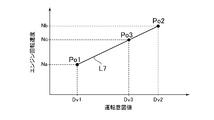
- FIG. 6 is a diagram for explaining an example of processing of the calculation unit 12c.
- the horizontal axis represents the driving intention value
- the vertical axis represents the engine rotation speed.
- a line L7 in the figure is a straight line passing through the point Po1 (operation intention value Dv1, first basic engine rotation speed Na) and the point Po2 (operation intention value Dv2, second basic engine rotation speed Nb).
- the driving intention value is Dv3 (Dv1 ⁇ Dv3 ⁇ Dv2)
- the calculation unit 12c calculates the engine rotation speed Nc at the point Po3 (driving intention value Dv3, engine rotation speed Nc) on the line L7 as the reference target engine rotation speed. (Na ⁇ Nc ⁇ Nb). That is, in the example of FIG.
- the calculation unit 12 c linearly complements the engine rotation speed with the driving intention value between the first basic engine rotation speed Na and the second basic engine rotation speed Nb, and the driving intention acquisition unit 17.
- the engine rotational speed corresponding to the driving intention value Dv3 calculated by the above is used as the reference target engine rotational speed.
- the driving intention value Dv1 is the minimum value of the driving intention value that can be calculated by the driving intention acquisition unit 17 and the driving intention value Dv2 is the maximum value of the driving intention value that can be calculated by the driving intention acquisition unit 17. That is, when the driving intention acquisition unit 17 calculates the minimum value of the driving intention value, the first basic engine rotation speed Na is calculated as the reference target engine rotation speed. On the other hand, when the driving intention acquisition unit 17 calculates the maximum value of the driving intention value, the second basic engine rotation speed Nb is calculated as the reference target engine rotation speed.
- the driving intention value may be a value lower than the driving intention value Dv1.
- the calculation unit 12c sets the first basic engine rotation speed as the reference target engine rotation speed regardless of the driving intention value, for example.
- the driving intention value may be higher than the driving intention value Dv2.
- the calculation unit 12c sets the second basic engine rotation speed as the reference target engine rotation speed regardless of the driving intention value.
- the driving intention acquisition unit 17 calculates a driving intention value based on the driving state of the vehicle detected by the sensor. For example, the driving intention acquisition unit 17 calculates the driving intention value based on at least one parameter selected from the accelerator operation amount, the vehicle speed, the accelerator operation amount change speed that is a differential value of the accelerator operation amount, and the acceleration.
- the driving intention acquisition unit 17 calculates the first load state value based on the accelerator operation amount and the vehicle speed. Further, the driving intention acquisition unit 17 calculates the second load state value based on the change speed of the accelerator operation amount. Furthermore, the driving intention acquisition unit 17 calculates the third load state value based on the vehicle speed and the acceleration of the vehicle. The driving intention acquisition unit 17 calculates the driving intention value by using all or part of these load state values.
- Each load state value is a numerical value for evaluating the possibility that the load applied to the engine 4 changes.
- the driving intention acquisition unit 17 increases as the load applied to the engine changes. Calculate the intended value.
- the driving intention acquisition unit 17 increases as the possibility that the load applied to the engine changes is low. Is calculated.
- FIG. 7A is an example of a map that associates the accelerator operation amount, the vehicle speed, and the first load state value.
- the solid line indicates the contour line of the first load state value.
- the first load state value is relatively small in an operation region (for example, a region where both the vehicle speed and the accelerator operation amount are medium) in which the possibility that the load is unlikely to change is low.
- the driving intention acquisition unit 17 refers to this map, for example, and calculates the first load state value from the accelerator operation amount and the vehicle speed detected based on the output of the sensor.
- FIG. 7B is an example of a map that associates the change speed of the accelerator operation amount with the second load state value. Also in this map, the second load state value is relatively small in the driving region in which the possibility that the load changes is small, that is, in the driving region where the change speed of the accelerator operation amount is small.
- the driving intention acquisition unit 17 calculates the change speed of the accelerator operation amount, and then calculates a second load state value corresponding to the calculated change speed of the accelerator operation amount with reference to this map.
- FIG. 7C is an example of a map that associates the vehicle speed, the acceleration of the vehicle, and the third load state value.
- the solid line shows the contour line of the third load state value.
- the third load state value is small in the driving region in which the possibility that the load will change is low, specifically, in the driving region where the vehicle speed is medium and the acceleration is small.
- the driving intention acquisition unit 17 refers to this map and calculates a third load state value corresponding to the vehicle speed and acceleration detected based on the output of the sensor.
- the driving intention acquisition unit 17 may select a load state value to be used for calculating the driving intention value from among the three load state values described above, and calculate the driving intention value based on the selected load state value. For example, the driving intention acquisition unit 17 calculates the driving intention value using all the load state values when the signs of all the load state values match. On the other hand, if there is one of the three load state values whose signs do not match, the driving intention acquisition unit 17 does not use any load state value and does not calculate the driving intention value in the current process. That is, the driving intention acquisition unit 17 does not update the driving intention value obtained in the previous process. Further, the driving intention acquisition unit 17 selects a load state value having the same sign from the first load state value, the second load state value, and the third load state value, and uses the selected load state value to drive A value may be calculated.
- the driving intention acquisition unit 17 may calculate the driving intention value based on the selected load state value and the driving intention value obtained in the previous process. For example, the driving intention acquisition unit 17 may calculate a product of the selected load state values, add the product to the driving intention value obtained in the previous process, and use the result of the addition as a new driving intention value. Further, the driving intention acquisition unit 17 may calculate the sum of the selected load state values, add the sum to the driving intention value obtained in the previous process, and use the result of the addition as a new driving intention value. Further, the driving intention acquisition unit 17 calculates the average value or median value of the selected load state values, adds the average value or median value to the driving intention value obtained in the previous process, and newly adds the result of the addition. A good driving intention value may be used.
- the driving intention acquisition unit 17 limits the change of the driving intention value when the vehicle is in a predetermined traveling state. For example, the driving intention acquisition unit 17 limits the change of the driving intention value so that a decrease in the reference target engine rotation speed can be suppressed in a driving situation where it is estimated that the acceleration request from the driver increases. That is, the driving intention acquisition unit 17 drives the driving intention value so that the change of the reference target engine rotation speed toward the first basic engine rotation speed is suppressed in a driving situation where it is estimated that the acceleration request from the driver increases. Limit changes in In other words, the driving intention value at which the first basic engine rotation speed is calculated as the reference target engine rotation speed is the first value, and the driving intention value at which the second basic engine rotation speed is calculated is the first target engine rotation speed. When the value is 2, the driving intention acquisition unit 17 limits the change from the second value of the driving intention value toward the first value.
- the driving intention acquisition unit 17 maintains the driving intention value at a value when the vehicle enters the traveling state until the vehicle leaves the above-described traveling state. In another example of the restriction, the driving intention acquisition unit 17 may change the driving intention value toward the second value until the vehicle exits the above-described predetermined traveling state.
- the change in the reference target engine speed itself is not suppressed, but the change in the driving intention value is suppressed. Therefore, although the change of the relative relationship (for example, difference) of the reference target engine rotational speed with respect to the first basic engine rotational speed and the second basic engine rotational speed is suppressed, the first basic engine speed is changed when the accelerator operation amount changes. Since the engine speed and the second basic engine speed change, the reference target engine speed itself changes.
- An example of a driving situation in which the driver's acceleration request is estimated to increase is a situation where the vehicle is turning.
- the vehicle speed is reduced, and then when the vehicle starts straight running, the driver increases the acceleration request and the vehicle speed increases. Determination of whether or not the vehicle is turning can be performed as follows.
- the car body is tilted.
- the tire contacts the ground not at the center in the width direction but at a position close to the side of the tire (hereinafter, a portion of the tire surface that contacts the ground is referred to as a ground contact point).
- the distance between the ground contact point and the axle (the rotation radius of the front wheel and the rotation radius of the rear wheel) is reduced. Since there is a difference between the tire thickness of the front wheel (tire radius of the tire) and the tire thickness of the rear wheel (radius of the tire cross section), the reduction rate of the rotation radius of the front wheel and the rear wheel There is a difference between the reduction rate of the turning radius.
- the driving intention acquisition unit 17 determines whether or not the vehicle is turning based on the difference between the vehicle speed calculated from the rotational speed of the front wheels 2 and the vehicle speed calculated from the rotational speed of the rear wheels 8. .
- the determination of whether or not the vehicle is turning is not limited to the above-described processing.
- a motorcycle may be provided with an acceleration sensor for detecting the inclination of the vehicle body in the left-right direction.
- the driving intention acquisition unit 17 determines that the vehicle is turning, for example, when the vehicle body is tilted and the vehicle speed is higher than the threshold value.
- the motorcycle 1 is provided with, for example, a switch 29 for detecting an operation of the brake lever 3b and a sensor for detecting an operating state of a brake device provided on the front wheel 2 or the rear wheel 8.
- the driving intention acquisition unit 17 determines whether or not the brake device is operating based on the outputs of the switches and sensors.
- the driving intention acquisition unit 17 calculates a traveling load based on, for example, the vehicle speed, the current engine speed, and the current throttle opening, and determines whether or not the vehicle is traveling uphill based on the traveling load. .
- the acceleration of the vehicle is a
- the weight of the vehicle is M
- the engine torque is Teg
- the inertia torque of the engine 4 is Ti
- the mechanical loss of torque in the path from the CVT 5 to the rear wheel 8 is Tloss.
- the total traveling load acting on the vehicle is Lv
- the total travel load Lv includes travel resistance (hereinafter referred to as reference travel resistance) when traveling on a horizontal road such as air resistance.
- (Teg ⁇ Ti) ⁇ speed ratio ⁇ Tloss (M ⁇ a + Lv) ⁇ k
- the engine torque Teg is calculated by referring to an engine torque map showing the relationship among the throttle opening, the engine speed, and the engine torque.
- the inertia torque Ti is a value obtained by multiplying the change speed of the engine rotation speed by the inertia moment of the mechanism (crankshaft or piston of the engine 4) upstream of the CVT 5.
- the gear ratio is, for example, the actual gear ratio of the current CVT 5 and can be calculated from the actual engine speed and the vehicle speed detected through a sensor.
- k is a coefficient obtained from the radius of the rear wheel 8 and the reduction ratio of the final reduction mechanism 7. Therefore, for example, the driving intention acquisition unit 17 calculates the engine torque Teg based on the engine speed and the throttle opening, and based on the engine torque Teg, the engine speed changing speed, and the vehicle speed, the relationship described above.
- the total travel load Lv is calculated from the equation.
- the driving intention acquisition unit 17 calculates a value obtained by subtracting the reference traveling resistance due to air resistance or the like from the total traveling load Lv as the traveling load.
- the travel load calculated in this way is generally a positive value when the vehicle is traveling uphill.
- the reference running resistance increases as the vehicle speed increases.
- the relationship between the vehicle speed and the reference running resistance is obtained in advance through experiments or the like. Therefore, the driving intention acquisition unit 17 refers to, for example, a map or a relational expression that associates the vehicle speed with the reference running resistance, and calculates the reference running resistance based on the vehicle speed.
- the processing of the driving intention acquisition unit 17 is not limited to that described above.
- the motorcycle 1 may have an operation member for accepting a driver's request for the travel mode of the vehicle.
- the motorcycle 1 may include an operation member that allows the driver to input a degree of request for travel with good acceleration response.
- the driving intention acquisition unit 17 detects the operation amount of the operation member and sets the operation amount as the driving intention value.
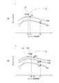
- FIG. 8 is a diagram for explaining the outline of the processing.
- the horizontal axis in the figure is the engine rotation speed, and the vertical axis is the engine torque.
- a torque curve representing the relationship between the engine torque and the engine rotation speed is drawn.
- FIG. 4A shows a torque curve when the throttle opening is Th1, Th2, and
- FIG. 4B shows a torque curve when the throttle opening is Th1, Th4, Th6.
- a line A is a curve (hereinafter referred to as the best fuel consumption curve) indicating an operation point at which the fuel consumption becomes the best.
- 6A and 6B indicates an operation point at which the same engine output (engine torque ⁇ engine rotation speed) as the operation point P1 (engine rotation speed N1, throttle opening Th1) can be obtained. It is an output curve.
- a line L4 in FIG. 5B is an equal output curve indicating an operation point at which the same engine output as the operation point P4 (engine speed N1, throttle opening Th4) can be obtained.
- the engine speed N1 is the reference target engine speed
- the throttle opening Th1 is a throttle opening (hereinafter referred to as a reference throttle opening) converted from the accelerator operation amount.
- control apparatus 10 of this embodiment may perform one or both of the rotational speed correction which is correction
- the target engine speed calculation unit 12 calculates the reference target engine speed N1 as described above.
- the target engine rotational speed calculation unit 12 corrects the reference target engine rotational speed N1, and sets the result of the correction as the final target engine rotational speed.
- the target engine rotation speed calculation unit 12 calculates the final target engine rotation speed based on the reference target engine rotation speed so that the fuel consumption is improved as compared with driving the engine 4 at the reference target engine rotation speed.
- the target engine speed calculation unit 12 sets an engine speed N2 between the reference target engine speed N1 and the best fuel efficiency engine speed N3 as the final target engine speed N2.
- the final target engine speed is gradually changed from the reference target engine speed N1 toward the best fuel efficiency engine speed N3.
- the target engine rotation speed calculation unit 12 may subtract a predetermined rotation speed from the reference target engine rotation speed N1 and use the subtraction result as the final target engine rotation speed.
- the target transmission ratio calculation unit 13 calculates the target transmission ratio of the CVT 5 based on the final target engine rotation speed, and the control device 10 drives the CVT actuator 25 so that the actual transmission ratio matches the target transmission ratio.
- the engine rotation speed at the operation point P1 shown in FIG. 8A is the reference target engine rotation speed N1.
- the throttle opening Th1 at the operating point P1 is a value obtained by converting the accelerator operation amount into the throttle valve angle.
- the controller 10 obtains the engine output (output indicated by the line L3) at the operation point P1 while driving the engine 4 at the final target engine rotational speed N2.
- Set the target throttle opening so that Therefore, in this case, the throttle opening Th2 at the operation point P2 is set as the target throttle opening.
- the operation point P2 is an operation point at which an engine output equal to the operation point P1 can be obtained and the engine rotation speed becomes the final target engine rotation speed N2.
- the control device 10 drives the throttle actuator 23 so that the actual throttle opening matches the target throttle opening.
- the control device 10 performs the following processing to calculate the target throttle opening.
- the target driving force calculation unit 15 calculates the driving force of the vehicle at the driving point P1 based on the reference target engine speed N1 and the accelerator operation amount (specifically, the throttle opening degree Th1 converted from the accelerator operation amount).
- the driving force is set as a reference target driving force.
- the target throttle opening calculation unit 16 sets the final target engine rotational speed N2 and the reference target driving force so that a driving force corresponding to the reference target driving force can be obtained while driving the engine 4 at the final target engine rotational speed N2. Based on this, the target throttle opening degree Th2 is calculated.
- the reference target driving force refers to the above-described target driving force (for example, the target value for the torque of the rear wheel 8 and the output of the rear wheel 8 (torque of the rear wheel 8 ⁇ rotational speed of the rear wheel 8).
- This is the target value from which the target value) is based. That is, when a correction process for a driving force described later is performed, a value obtained by correcting the reference target driving force is a target driving force. When such a correction process is not performed, the reference target driving force is corrected. Is the target driving force.
- the torque of the rear wheel 8 and the output of the rear wheel 8 are proportional to the engine output. Therefore, as shown in FIG. 8A, by setting the torque of the rear wheel 8 at the driving point P1 and the output of the rear wheel 8 as target values, the engine speed is maintained while maintaining the engine output at the driving point P1. Can be changed.
- the target engine rotational speed calculation unit 12 sets the reference target engine rotational speed N1 as the final target engine rotational speed when the rotational speed correction is not performed.
- the control device 10 obtains an engine output higher or lower than the engine output at the operation point P1 while driving the engine 4 at the final target engine rotational speed N1.
- the target throttle opening is set so that For example, as shown in FIG. 8B, the control device 10 can obtain the engine output indicated by the line L4 higher than the engine output indicated by the line L3 while driving the engine 4 at the final target engine speed N1.
- the throttle opening Th4 at the operation point P4 is set as the target throttle opening.
- the operation point P4 is an operation point on the line L4 where the engine rotation speed is N1.
- the control device 10 performs the following processing in order to calculate the target throttle opening when performing the driving force correction.
- the target driving force calculation unit 15 calculates the driving force of the vehicle at the driving point P1 based on the reference target engine speed N1 and the accelerator operation amount (specifically, the throttle opening degree Th1 converted from the accelerator operation amount).
- the driving force is set as a reference target driving force. Thereafter, the target driving force calculation unit 15 corrects the calculated reference target driving force, and uses the corrected driving force as the target driving force.
- the target throttle opening calculation unit 16 can obtain a driving force corresponding to the target driving force while driving the engine 4 at the target engine rotation speed N1 (equal to the reference target engine rotation speed when the rotation speed correction is not performed). Then, the target throttle opening degree Th4 is calculated based on the target engine speed N1 and the target driving force.
- Rotational speed correction and driving force correction are executed when predetermined conditions are satisfied. For example, in a motorcycle provided with an operation member that enables selection of these two corrections, the driver selects one or both of the two corrections through the operation member.
- the control device 10 executes correction according to the operation. Further, when it is detected that the vehicle is traveling uphill, the target driving force calculation unit 15 may perform driving force correction. Further, the target engine rotation speed calculation unit 12 may perform rotation speed correction when the steady running of the vehicle continues for a certain time or more.
- the target engine rotation speed calculation unit 12 sets the final target engine rotation speed so that the fuel consumption is better than driving the engine 4 at the reference target engine rotation speed N1, and the target throttle opening calculation unit 16
- the target throttle opening is set so that an engine output higher or lower than the engine output at the operation point P1 can be obtained while driving the engine 4 at the target engine rotation speed.
- the target engine speed calculation unit 12 calculates the best fuel efficiency engine speed N5 of the engine output indicated by the line L4 and the reference target engine speed N1.
- the final target engine speed N6 is set in between.
- the target throttle opening calculation unit 16 sets the throttle opening Th6 at the operation point P6 as the target throttle opening so that the engine output indicated by the line L4 can be obtained while driving the engine 4 at the final target engine speed N6.
- the best fuel efficiency engine speed N5 is the engine speed at the driving point P5 that is the intersection of the line L4 and the best fuel efficiency curve A.
- the operation point P6 is an operation point on the line L4 where the engine speed is N6.
- the target engine rotation speed calculation unit 12 sets the reference target engine rotation speed N1 as the final target engine rotation speed, and the target throttle opening calculation unit 16 sets the engine at the operation point P1.
- the target throttle opening is set so that output can be obtained. Therefore, in this case, the throttle opening Th1 is set to the target throttle opening at the operation point P1.
- the target engine rotation speed calculation unit 12 includes a correction unit 12B as shown in FIG.
- the correcting unit 12B calculates the final target engine speed based on the reference target engine speed. Specifically, as described with reference to FIG. 8, when the correction unit 12B does not execute the rotation speed correction, the correction target 12B sets the reference target engine rotation speed as the final target engine rotation speed. On the other hand, when executing the rotational speed correction, the correction unit 12B uses the best fuel efficiency engine rotational speed so that the fuel efficiency can be improved rather than driving the engine at the standard target engine rotational speed. Correction is made, and the result of the correction is made the final target engine speed.
- Rotation speed correction has various forms.
- the correction unit 12B gradually brings the final target engine speed from the reference target engine speed to the best fuel efficiency engine speed.
- the final target engine rotation speed gradually becomes the best.
- the correction amount is gradually changed so as to approach the fuel consumption engine rotation speed.
- the gradual change of the correction amount can be performed by repeatedly executing a process of adding or subtracting a predetermined value to the correction amount calculated in the previous process, for example.
- the correction unit 12B may integrate the difference between the reference target engine rotation speed and the best fuel efficiency engine rotation speed with time, and calculate the correction amount based on the integration value.
- a filter represented by a transfer function having a large time constant may be used for calculating the correction amount. Even in this case, a gradual change in the correction amount can be realized. In this way, by slowly changing the correction amount, even if the reference target engine speed changes due to, for example, a change in the accelerator operation amount, the change in the correction amount is small.
- the final target engine speed also changes by an amount corresponding to.
- the target gear ratio calculation unit 13 calculates the target gear ratio so that the actual engine speed becomes the final target engine speed. That is, the target speed ratio calculation unit 13 calculates the target speed ratio based on the final target engine speed and the speed of the mechanism downstream of the CVT 5.
- the target speed ratio calculation unit 13 in this example calculates the target speed ratio based on the final target engine speed and the vehicle speed detected by the sensor. For example, the target speed ratio calculation unit 13 calculates the target speed ratio based on a value obtained by dividing the final target engine rotation speed by the vehicle speed and the speed reduction ratio of the final speed reduction mechanism 7. When the speed ratio calculated in this way exceeds the upper limit or lower limit of the speed ratio of the CVT 5, the target speed ratio calculating unit 13 sets the upper limit or the lower limit as the target speed ratio.
- the control device 10 includes the reference throttle opening calculation unit 14 and the target driving force calculation unit 15 (see FIG. 3).
- the reference throttle opening calculation unit 14 converts the accelerator operation amount detected by the sensor into a throttle opening (throttle valve angle) using a map or relational expression stored in the storage device 10c in advance, and the result Is the reference throttle opening.
- the target driving force calculation unit 15 calculates a target value relating to the driving force of the vehicle, that is, the above-described target driving force based on the accelerator operation amount (more specifically, the reference throttle opening).
- the target driving force is, for example, the torque of the rear wheel 8 or the output of the rear wheel 8 (torque ⁇ rotational speed of the rear wheel 8).
- the target driving force calculation unit 15 includes a reference target driving force calculation unit 15A and a correction unit 15B.
- the reference target driving force calculation unit 15A calculates a reference target driving force based on the reference throttle opening and the engine speed obtained from the basic information.
- the reference target driving force is a target value input to the correction unit 15B described later.
- the reference target driving force calculation unit 15A calculates the reference target driving force based on the reference throttle opening and the reference target engine rotational speed obtained by referring to the first basic information and the second basic information. . This process is executed as follows, for example.
- an engine torque map that associates the engine speed, the throttle opening, and the engine torque is stored in the storage device 10c in advance.
- the reference target driving force calculation unit 15A calculates an engine torque corresponding to the reference target engine rotation speed and the reference throttle opening from the engine torque map (this engine torque is referred to as a reference target engine torque).
- the reference target driving force calculation unit 15A uses a map that associates the engine rotation speed, the throttle opening, and the engine output in place of the engine torque map, and from this map, the reference target engine rotation speed and the reference An engine output corresponding to the throttle opening may be calculated (this engine output is referred to as a reference target engine output).
- the reference target driving force calculation unit 15A converts the calculated reference target engine torque or reference target engine output into the torque of the rear wheel 8 or the output of the rear wheel 8, and uses the result as the reference target driving force. For example, when the target value for the torque of the rear wheel 8 is set as the target driving force, the reference target driving force calculation unit 15A calculates the inertia torque of the engine 4 based on the change speed of the reference target engine rotation speed. Then, the inertia torque is subtracted from the reference engine torque (reference engine torque-inertia torque), and the result of the subtraction is used as the reference target driving force.
- the reference target driving force calculation unit 15A subtracts the amount of change in output caused by the inertia torque from the reference engine output (reference engine output-inertia torque).
- the amount of change in output due to the above) and the result of the subtraction are used as the reference target driving force.
- the subtraction of the inertia torque or the change amount of the output due to the inertia torque does not necessarily have to be performed.
- the reference target driving force calculation unit 15A may subtract the torque lost in the CVT 5 in the process of transmitting the torque of the engine 4 to the rear wheel 8 or the output loss caused by the torque. Then, the result of the subtraction may be used as the reference target driving force.
- the torque lost in the CVT 5 can be calculated based on the rotational speed of the output shaft of the CVT 5 and the engine torque, for example, due to the torque lost to rotate the belt.
- the calculation of the reference target driving force is not limited to that described above.
- the reference target driving force may be calculated based on the first basic engine rotation speed or the second basic engine rotation speed instead of the reference target engine rotation speed.
- the reference target driving force calculation unit 15A refers to the engine torque map, calculates the engine torque corresponding to the first basic engine rotation speed and the reference throttle opening as the reference engine torque, and calculates the reference target from the reference engine torque.
- the driving force may be calculated.
- the correction unit 15B sets the reference target driving force as the target driving force when the driving force correction is not executed. On the other hand, when executing the driving force correction, the correcting unit 15B sets a value obtained by correcting the reference target driving force as the target driving force. Specifically, the correction unit 15B adds and / or multiplies a correction value to the reference target driving force and sets the calculation result as the target driving force.
- the correction unit 15B calculates a traveling load that acts on the vehicle when the vehicle travels uphill, and adds or multiplies a correction value according to the traveling load to the reference target driving force.
- the traveling load is calculated based on, for example, engine torque calculated based on the engine speed and the throttle opening, the engine speed changing speed, and the vehicle speed. Can be calculated based on
- the correction unit 15B increases the target driving force more than the reference target driving force or increases the reference target driving force when the reference target driving force increases, that is, when the vehicle is about to accelerate.
- the target drive force increase speed is made slower than the increase speed.
- the correction unit 15B may make the lowering speed of the target driving force slower than the lowering speed of the reference target driving force when the reference target driving force increases and then decreases.
- Such a change in the target driving force can be realized, for example, by using a filter represented by a transfer function including a proportional element and a first-order lag element with respect to the reference target driving force.
- the target throttle opening calculation unit 16 drives the engine 4 at the final target engine rotational speed, and the target throttle opening based on the target driving force and the final target engine rotational speed so that the driving force of the vehicle becomes the target driving force. Is calculated.
- the target throttle opening calculation unit 16 in the example shown in FIG. 3 includes a target engine torque calculation unit 16A and a throttle opening calculation unit 16B.
- the target engine torque calculation unit 16A converts the target driving force, which is a target value for the torque and output of the rear wheels 8, into the target engine torque (that is, target engine torque) using the final target engine rotation speed.
- the throttle opening calculation unit 16B calculates the target throttle opening based on the target engine torque and the final target engine speed.
- the target engine torque calculation unit 16A calculates the inertia torque of the engine 4 based on the change speed of the final target engine rotation speed, and based on the inertia torque, the torque lost in the CVT 5, and the final target engine rotation speed.
- the target driving force is converted into the target engine torque.
- the target driving force is a target value for the torque of the rear wheel 8
- the target engine torque calculation unit 16A is opposite to the reference target driving force calculation unit 15A, and the inertia torque and the torque lost in the CVT 5 Is added to the target driving force, and the result is the target engine torque.
- the target engine torque calculation unit 16A is, for example, the output change amount caused by the inertia torque and the CVT 5 in contrast to the reference target driving force calculation unit 15A.
- the output loss resulting from the lost torque is added to the target driving force, and the target engine torque is calculated based on the result of the addition (target engine output) and the final target engine speed.
- the throttle opening calculation unit 16B calculates a target throttle opening based on the target engine torque. Specifically, the throttle opening calculation unit 16B refers to a map that associates the engine torque, the throttle opening, and the engine rotation speed, and calculates the throttle opening that corresponds to the target engine torque and the final target engine rotation speed. The throttle opening is set as the target throttle opening.
- the processing of the target throttle opening calculation unit 16 is not limited to that described above.
- the target throttle opening calculation unit 16 calculates a target engine output based on the target driving force
- the throttle opening calculation unit 16B calculates the target throttle opening based on the target engine output.
- the storage device 10c stores a map that associates the engine output, the throttle opening, and the engine rotation speed. Then, the throttle opening calculation unit 16B refers to this map and calculates the target throttle opening based on the target engine output and the target engine rotation speed.
- the target engine rotational speed calculation unit 12 calculates the best fuel efficiency engine rotational speed when performing rotational speed correction, and the final target engine rotational speed based on the best fuel efficiency engine rotational speed and the reference target engine rotational speed. Is set.
- the best fuel efficiency engine rotational speed is calculated using, for example, the target driving force calculated by the target driving force calculation unit 15.
- the relationship between the output of the rear wheel 8 and the best fuel consumption engine rotation speed is stored in the storage device 10c.
- the target engine rotation speed calculation unit 12 refers to this map, and the best corresponding to the target driving force calculated by the target driving force calculation unit 15 is obtained.
- the fuel consumption engine rotation speed is calculated.
- the target engine rotational speed calculation unit 12 defines the best fuel consumption curve, for example, by multiplying the target driving force by the rotational speed of the rear wheel 8. In the map, the best fuel consumption engine speed corresponding to the multiplication result is calculated.
- the first basic engine rotation speed calculation unit 12a performs the first operation based on the first basic information that defines the engine rotation speed in the first operation mode (for example, the above-described low fuel consumption mode).
- the engine speed is calculated.
- the second basic engine rotational speed calculation unit 12b calculates the second engine rotational speed from the second basic information that defines the engine rotational speed in the second operation mode (for example, the acceleration response mode described above). Yes.
- the driving intention acquisition unit 17 acquires a driving intention value that is a numerical value representing the driving intention of the driver, and the target engine rotation speed calculation unit 12 calculates between the first engine rotation speed and the second engine rotation speed.
- the target engine speed (the final target engine speed in the above description) is calculated on the basis of the engine speed (in the above description, the reference target engine speed) corresponding to the driving intention value.
- the target gear ratio calculation unit 13 calculates the target gear ratio of the CVT 5 based on the final target engine rotation speed
- the throttle opening calculation unit 16B calculates the target driving force calculated based on the accelerator operation amount detected by the sensor.
- the target throttle opening is calculated based on the final target engine speed.
- the target engine rotation speed is calculated first, and then the target value related to the driving force is calculated. Therefore, it is possible to suppress the target value relating to the driving force of the vehicle from affecting the setting of the target engine speed. As a result, it becomes easy to control the engine speed so that a comfortable riding feeling can be obtained.
- the driving intention value is used to calculate the target engine rotation speed, an engine rotation speed suitable for the driver's driving intention can be realized.
- the engine rotation speed defined by the second basic information is a rotation speed that can realize an acceleration response better than the engine rotation speed defined by the first basic information, as described above.
- the target engine speed specifically, the reference target engine speed
- the target engine speed is obtained from the second basic information. It is possible to set the rotation speed close to the engine rotation speed.
- the present invention is not limited to the control device 10 described above, and various modifications can be made.
- the change of the driving intention value is restricted in a situation where the vehicle is turning.
- the limitation on the change in the driving intention value is not necessarily executed.
- control device 10 was able to perform both rotation speed correction and driving force correction.
- the control device 10 may be capable of only one of rotational speed correction and driving force correction.
- the control device 10 may not be able to perform both the rotational speed correction and the driving force correction. That is, the target driving force calculation unit 15 does not necessarily include the correction unit 15B. Further, the target engine rotation speed calculation unit 12 does not necessarily include the correction unit 12B.
- the target driving force and the reference target driving force are the target rear wheel 8 output or the rear wheel 8 torque.
- these may be target engine outputs or vehicle accelerations.
- the target engine rotational speed output by the correction unit 12B is referred to as the final target engine rotational speed.
- the final target engine rotational speed is further corrected, and based on the corrected target engine rotational speed.
- the target gear ratio and the like may be calculated.
Landscapes
- Engineering & Computer Science (AREA)
- Mechanical Engineering (AREA)
- Chemical & Material Sciences (AREA)
- Combustion & Propulsion (AREA)
- General Engineering & Computer Science (AREA)
- Transportation (AREA)
- Automation & Control Theory (AREA)
- Control Of Vehicle Engines Or Engines For Specific Uses (AREA)
- Combined Controls Of Internal Combustion Engines (AREA)
- Control Of Transmission Device (AREA)
- Control Of Driving Devices And Active Controlling Of Vehicle (AREA)
- Electrical Control Of Air Or Fuel Supplied To Internal-Combustion Engine (AREA)
Abstract
L'invention concerne un dispositif de commande de véhicule qui commande électroniquement le rapport de transmission et la position du papillon d'une transmission à variation continue, au moyen duquel une expérience de conduite confortable peut être obtenue et une vitesse de rotation de moteur correspondant à l'intention de conduite du conducteur est réalisée. Une première carte prescrivant la vitesse de rotation de moteur dans un premier mode de conduite et une seconde carte prescrivant la vitesse de rotation de moteur dans un second mode de conduite sont stockées dans un dispositif de stockage. Le dispositif de commande obtient une valeur d'intention de conduite, qui est une valeur numérique représentant l'intention de conduite du conducteur. Le dispositif de commande calcule une vitesse de rotation de moteur cible de référence correspondant à la valeur d'intention de conduite entre une première vitesse de rotation de moteur calculée à partir de la première carte et une seconde vitesse de rotation de moteur calculée à partir de la seconde carte, et calcule une vitesse de rotation de moteur cible à partir de la vitesse de rotation de moteur cible de référence. Le dispositif de commande calcule un rapport de transmission cible à partir de la vitesse de rotation de moteur cible. Le dispositif de commande calcule une valeur cible concernant la force d'entraînement du véhicule sur la base de la vitesse de rotation de moteur cible, et calcule une position du papillon cible de façon à obtenir une force d'entraînement correspondant à la valeur cible.
Priority Applications (2)
| Application Number | Priority Date | Filing Date | Title |
|---|---|---|---|
| JP2015505535A JP6082804B2 (ja) | 2013-03-12 | 2014-03-12 | 車両の制御装置、及びそれを備える自動二輪車 |
| EP14763448.9A EP2974929B1 (fr) | 2013-03-12 | 2014-03-12 | Dispositif de commande de véhicule et motocycle équipé de celui-ci |
Applications Claiming Priority (2)
| Application Number | Priority Date | Filing Date | Title |
|---|---|---|---|
| JP2013049636 | 2013-03-12 | ||
| JP2013-049636 | 2013-03-12 |
Publications (1)
| Publication Number | Publication Date |
|---|---|
| WO2014142210A1 true WO2014142210A1 (fr) | 2014-09-18 |
Family
ID=51536861
Family Applications (1)
| Application Number | Title | Priority Date | Filing Date |
|---|---|---|---|
| PCT/JP2014/056583 Ceased WO2014142210A1 (fr) | 2013-03-12 | 2014-03-12 | Dispositif de commande de véhicule et motocycle équipé de celui-ci |
Country Status (3)
| Country | Link |
|---|---|
| EP (1) | EP2974929B1 (fr) |
| JP (1) | JP6082804B2 (fr) |
| WO (1) | WO2014142210A1 (fr) |
Citations (5)
| Publication number | Priority date | Publication date | Assignee | Title |
|---|---|---|---|---|
| JP2000356146A (ja) * | 1999-06-11 | 2000-12-26 | Nissan Motor Co Ltd | 車両用パワートレーンの変速制御装置 |
| JP2005001485A (ja) * | 2003-06-11 | 2005-01-06 | Nissan Motor Co Ltd | 車両の駆動力制御装置 |
| JP2005508788A (ja) * | 2001-11-10 | 2005-04-07 | ローベルト ボツシユ ゲゼルシヤフト ミツト ベシユレンクテル ハフツング | 連続的に調整可能なトランスミッションを有する車両において機関トルクとトランスミッション変速比とを設定するシステムおよび方法 |
| JP3754188B2 (ja) | 1997-09-08 | 2006-03-08 | 日産自動車株式会社 | 車両の駆動力制御装置 |
| WO2012017709A1 (fr) * | 2010-08-04 | 2012-02-09 | ヤマハ発動機株式会社 | Véhicule et son dispositif de commande d'entraînement |
Family Cites Families (4)
| Publication number | Priority date | Publication date | Assignee | Title |
|---|---|---|---|---|
| JP2898034B2 (ja) * | 1989-12-29 | 1999-05-31 | アイシン・エィ・ダブリュ株式会社 | 無段変速機の制御装置 |
| US5612873A (en) * | 1992-12-17 | 1997-03-18 | Honda Giken Kogyo Kabushiki Kaisha | Speed ratio control method and device for continuously variable transmission |
| EP2467288B1 (fr) * | 2009-08-18 | 2022-06-15 | Toyota Jidosha Kabushiki Kaisha | Système contrôle véhicule |
| JP5510227B2 (ja) * | 2010-09-15 | 2014-06-04 | トヨタ自動車株式会社 | 車両制御装置 |
-
2014
- 2014-03-12 WO PCT/JP2014/056583 patent/WO2014142210A1/fr not_active Ceased
- 2014-03-12 EP EP14763448.9A patent/EP2974929B1/fr active Active
- 2014-03-12 JP JP2015505535A patent/JP6082804B2/ja active Active
Patent Citations (5)
| Publication number | Priority date | Publication date | Assignee | Title |
|---|---|---|---|---|
| JP3754188B2 (ja) | 1997-09-08 | 2006-03-08 | 日産自動車株式会社 | 車両の駆動力制御装置 |
| JP2000356146A (ja) * | 1999-06-11 | 2000-12-26 | Nissan Motor Co Ltd | 車両用パワートレーンの変速制御装置 |
| JP2005508788A (ja) * | 2001-11-10 | 2005-04-07 | ローベルト ボツシユ ゲゼルシヤフト ミツト ベシユレンクテル ハフツング | 連続的に調整可能なトランスミッションを有する車両において機関トルクとトランスミッション変速比とを設定するシステムおよび方法 |
| JP2005001485A (ja) * | 2003-06-11 | 2005-01-06 | Nissan Motor Co Ltd | 車両の駆動力制御装置 |
| WO2012017709A1 (fr) * | 2010-08-04 | 2012-02-09 | ヤマハ発動機株式会社 | Véhicule et son dispositif de commande d'entraînement |
Non-Patent Citations (1)
| Title |
|---|
| See also references of EP2974929A4 |
Also Published As
| Publication number | Publication date |
|---|---|
| JP6082804B2 (ja) | 2017-02-15 |
| EP2974929A1 (fr) | 2016-01-20 |
| EP2974929A4 (fr) | 2017-01-04 |
| EP2974929B1 (fr) | 2022-05-04 |
| JPWO2014142210A1 (ja) | 2017-02-16 |
Similar Documents
| Publication | Publication Date | Title |
|---|---|---|
| JP5388303B2 (ja) | 無段変速機の変速制御装置 | |
| CN103118919B (zh) | 车辆控制系统 | |
| WO2013011572A1 (fr) | Appareil de commande de véhicule | |
| WO2012067234A1 (fr) | Véhicule à deux roues automatique et dispositif de commande associé | |
| WO2013046308A1 (fr) | Dispositif de commande de la force de propulsion d'un véhicule | |
| US20130073157A1 (en) | Enhanced torque model for vehicle having a cvt | |
| JP7545323B2 (ja) | 乗物制御プログラム及び乗物制御装置 | |
| CN101163618A (zh) | 驱动力控制设备和驱动力控制方法 | |
| JP6082805B2 (ja) | 車両の制御装置、及びそれを備える自動二輪車 | |
| JP5447670B2 (ja) | 車両の左右輪駆動力配分制御装置 | |
| JP6082804B2 (ja) | 車両の制御装置、及びそれを備える自動二輪車 | |
| JP5997362B2 (ja) | 車両の制御装置及び自動二輪車 | |
| EP2851253B1 (fr) | Procédé de commande de véhicule, dispositif de commande de véhicule et motocyclette le comportant | |
| JP5953369B2 (ja) | 鞍乗型車両及び鞍乗型車両の制御方法 | |
| JP5816363B2 (ja) | 車両の制御装置、車両の制御方法及び鞍乗型車両 | |
| WO2013172465A1 (fr) | Véhicule à monture à selle | |
| EP3121083B1 (fr) | Système de commande de puissance d'entraînement et véhicule comportant un système de commande de puissance d'entraînement | |
| JP5946524B2 (ja) | 車両の制御装置、及びそれを備える自動二輪車 | |
| JP2013252754A (ja) | 車両の駆動力制御装置 | |
| JP2017115935A (ja) | 車両の変速制御装置 | |
| JP2011037363A (ja) | 車両の駆動力制御装置 | |
| JP4424195B2 (ja) | 車両の制御装置 | |
| JP2013252755A (ja) | 車両の駆動力制御装置 | |
| JP2007192067A (ja) | 内燃機関の制御装置 | |
| JP2014148262A (ja) | 車両の制御装置 |
Legal Events
| Date | Code | Title | Description |
|---|---|---|---|
| 121 | Ep: the epo has been informed by wipo that ep was designated in this application |
Ref document number: 14763448 Country of ref document: EP Kind code of ref document: A1 |
|
| ENP | Entry into the national phase |
Ref document number: 2015505535 Country of ref document: JP Kind code of ref document: A |
|
| WWE | Wipo information: entry into national phase |
Ref document number: 2014763448 Country of ref document: EP |
|
| NENP | Non-entry into the national phase |
Ref country code: DE |