WO2014142294A1 - Lentille à plaques métalliques - Google Patents
Lentille à plaques métalliques Download PDFInfo
- Publication number
- WO2014142294A1 WO2014142294A1 PCT/JP2014/056836 JP2014056836W WO2014142294A1 WO 2014142294 A1 WO2014142294 A1 WO 2014142294A1 JP 2014056836 W JP2014056836 W JP 2014056836W WO 2014142294 A1 WO2014142294 A1 WO 2014142294A1
- Authority
- WO
- WIPO (PCT)
- Prior art keywords
- flat plate
- central
- metal plate
- flat
- flat plates
- Prior art date
- Legal status (The legal status is an assumption and is not a legal conclusion. Google has not performed a legal analysis and makes no representation as to the accuracy of the status listed.)
- Ceased
Links
Images











Classifications
-
- H—ELECTRICITY
- H01—ELECTRIC ELEMENTS
- H01Q—ANTENNAS, i.e. RADIO AERIALS
- H01Q15/00—Devices for reflection, refraction, diffraction or polarisation of waves radiated from an antenna, e.g. quasi-optical devices
- H01Q15/02—Refracting or diffracting devices, e.g. lens, prism
- H01Q15/10—Refracting or diffracting devices, e.g. lens, prism comprising three-dimensional [3D] array of impedance discontinuities, e.g. holes in conductive surfaces or conductive discs forming artificial dielectric
-
- H—ELECTRICITY
- H01—ELECTRIC ELEMENTS
- H01Q—ANTENNAS, i.e. RADIO AERIALS
- H01Q15/00—Devices for reflection, refraction, diffraction or polarisation of waves radiated from an antenna, e.g. quasi-optical devices
- H01Q15/02—Refracting or diffracting devices, e.g. lens, prism
- H01Q15/04—Refracting or diffracting devices, e.g. lens, prism comprising wave-guiding channel or channels bounded by effective conductive surfaces substantially perpendicular to the electric vector of the wave, e.g. parallel-plate waveguide lens
-
- H—ELECTRICITY
- H01—ELECTRIC ELEMENTS
- H01P—WAVEGUIDES; RESONATORS, LINES, OR OTHER DEVICES OF THE WAVEGUIDE TYPE
- H01P3/00—Waveguides; Transmission lines of the waveguide type
- H01P3/20—Quasi-optical arrangements for guiding a wave, e.g. focusing by dielectric lenses
Definitions
- the present invention relates to a metal plate lens capable of focusing electromagnetic waves such as terahertz waves.
- the terahertz electromagnetic wave is an electromagnetic wave having a frequency of 0.1 to 10 THz (wavelength of 30 ⁇ m to 3000 ⁇ m), and the wavelength is almost the same as the far infrared to millimeter wave region. Since terahertz electromagnetic waves exist in a frequency region between “light” and “millimeter wave”, they have the ability to distinguish at high spatial resolution as well as light and the ability to transmit substances similar to millimeter waves. Have both.
- the terahertz wave band has been an undeveloped electromagnetic wave so far, and its application to characterization of materials by time-domain spectroscopy, imaging and tomography utilizing the characteristics of electromagnetic waves in this frequency band has been studied. When terahertz electromagnetic waves are used, both material permeability and straightness can be achieved, enabling safe and innovative imaging instead of X-rays and ultra-high-speed wireless communication of several hundred Gbps.
- This artificial structure in which the dielectric constant and permeability are negative is an artificial structure that is sufficiently larger than an atom and smaller than the light wavelength scale, and is called a metamaterial.
- a metamaterial having negative refraction is used, a complete lens having a planar structure can be created.
- a conventional lens has a diffraction limit in which a lens having a wavelength smaller than the wavelength of light cannot be observed, but a complete lens can observe even a fine lens exceeding the diffraction limit.
- a unit cell consisting of a split ring resonator showing negative permeability combining two large and small rings with cuts at opposite positions and a metal wire showing negative dielectric constant in a matrix form Arranged metamaterials are known (see Patent Document 1).
- the unit cell can be applied to a lens or the like by realizing a negative refractive index by arranging the unit cells along one axis so as to have a gradient refractive index.
- an object of the present invention is to provide a metal plate lens having a structure that can be easily formed even in a short wavelength region such as a terahertz wave without adopting a structure that realizes a negative refractive index. Yes.
- the metal plate lens of the present invention is parallel to the xz plane when the optical axis that is the central axis is the z axis and the axes orthogonal to the z axis are the x axis and the y axis.
- a plurality of through holes of a predetermined size are formed in the plurality of flat plates excluding the uppermost flat plate arranged at the top of the flat plates and the lowermost flat plate arranged at the bottom,
- a through hole having a first size is formed in a central flat plate disposed in a central portion of the flat plate, and between the central flat plate and the uppermost flat plate, and in the central flat plate And the middle flat plate disposed between the lowermost flat plate and the lowermost flat plate
- the through hole having a second size smaller than the first size is formed, and a plurality of through holes are formed between the central plate and the uppermost plate and between the central plate and the lowermost plate.
- the disposition position is farther from the central flat plate than the second size of the through hole formed in the intermediate flat plate at the disposition position close to the central flat plate.
- the most important feature is that the second size of the through hole formed in the intermediate plate is reduced.
- the metal plate lens of the present invention is a metal plate lens arranged so that metal flat plates overlap each other, and a through hole having a predetermined size is formed in a central flat plate and an intermediate flat plate.
- the size of the central flat plate is made larger than that of the intermediate flat plate.
- the through hole is formed at the wavelength of the electromagnetic wave propagating between the flat plates in which the through holes are formed. The wavelength becomes shorter than the wavelength of the electromagnetic wave propagating between the flat plates not formed, and the degree of the shorter wavelength becomes larger as the size of the through hole becomes larger.
- the wavelength of the electromagnetic wave propagating using the central flat plate is shorter than the wavelength of the electromagnetic wave propagating using the intermediate flat plate, and the wavelength of the electromagnetic wave propagating using the intermediate flat plate is equal to the formation of the through hole. It becomes shorter than the wavelength of the electromagnetic wave which propagates using the uppermost flat plate and the lowermost flat plate which are not made.
- the metal plate lens of the present invention acts as a lens by overlapping metal flat plates with through-holes as described above, and the metal plate lens of the present invention does not employ a structure that achieves a negative refractive index, such as terahertz waves. Even if it is applied to a region having a short wavelength, it can be easily created.
- FIG. 1 is a perspective view showing the configuration of the metal plate lens of the embodiment of the present invention.
- the metal plate lens 1 of the embodiment of the present invention shown in FIG. 1 is parallel to the xz plane when the optical axis that is the central axis is the z axis and the axes orthogonal to the z axis are the x axis and the y axis.
- 12 metal flat plates 10a, 10b, 11a, 11b, 12a, 12b, 13a, 13b, 14a, 14b, 15a, and 15b are arranged in parallel with each other at a predetermined interval. Has been configured.
- Through holes are not formed in the uppermost flat plate 10a arranged in the uppermost portion and the lowermost flat plate 10b arranged in the lowermost portion, but two central flat plates 15a and 15b arranged in the central portion, Four intermediate plates 11a, 12a, 13a, 14a disposed between the uppermost flat plate 10a and the central plate 15a, and four sheets disposed between the lowermost flat plate 10b and the central plate 15b.
- Each of the intermediate flat plates 11b, 12b, 13b, and 14b is formed with a through hole having a predetermined diameter.
- the lateral width is w
- the length in the optical axis (z-axis) direction is l (lower-case el)
- the height is h.
- a central flat plate 15a and a central flat plate 15b are arranged at a distance d1 in the center of the metal plate lens 1
- fourth intermediate flat plates 14a and 14b are arranged at a distance d2 on both sides thereof.
- third intermediate flat plates 13a and 13b are arranged on both sides of the fourth intermediate flat plates 14a and 14b with a distance d3, respectively, and second intermediate flat plates 12a on both sides of the third intermediate flat plates 13a and 13b.
- first intermediate flat plates 11a, 11b are arranged at a distance d5 on both sides of the second intermediate flat plates 12a, 12b. Then, the uppermost flat plate 10a and the lowermost flat plate 10b are arranged on both sides of the first intermediate flat plates 11a and 11b with a distance d6.
- the thicknesses of the flat plates 10a to 15b are uniform and t.
- FIG. 2 An example of dimensions when the design frequency of the metal plate lens 1 according to the present invention is 0.5 THz is shown in FIG.
- the wavelength of the design frequency is expressed as ⁇ .
- the length l of each flat plate 10a to 15b in the optical axis (z-axis) direction of the metal plate lens 1 according to the present invention is about 2.1 mm.
- the lateral width w of each of the flat plates 10a to 15b in the x-axis direction is about 4.2 mm (about 7.0 ⁇ )
- the height h of the metal plate lens 1 in the y-axis direction is about 3.77 mm (about 6.3 ⁇ )
- the distances d1 to d6 between the flat plates 10a to 15b are set to a uniform distance d of about 0.310 mm (about 0.52 ⁇ )
- the thickness t of each of the flat plates 10a to 15b is about 0.030 mm ( About 0.050 ⁇ ).
- FIGS. 3A is a plan view showing the configuration of the uppermost flat plate 10a and the lowermost flat plate 10b
- FIG. 3B is a plan view showing the configuration of the first intermediate flat plates 11a and 11b
- FIG. 4C is a plan view showing the configuration of the second intermediate flat plates 12a and 12b
- FIG. 4A is a plan view showing the configuration of the third intermediate flat plates 13a and 13b.
- FIG. 4C is a plan view showing the configuration of the central flat plates 15a and 15b.
- the uppermost flat plate 10a and the lowermost flat plate 10b are made of a horizontally long rectangular flat plate made of metal, and no through hole is formed.
- the first intermediate flat plates 11a and 11b are disposed adjacent to the inside of the uppermost flat plate 10a and the lowermost flat plate 10b, and are horizontally long made of the same shape metal.
- the through holes 11 having a predetermined radius and a radius r1 are formed on the entire surface at predetermined intervals.
- the through holes 11 are formed vertically and horizontally, and the interval at which the through holes 11 are formed is s. As shown in FIG.
- the second intermediate flat plates 12a and 12b are disposed adjacent to the inside of the first intermediate flat plates 11a and 11b, and are horizontally long made of the same shape metal.
- the through holes 11 having the radius r1 are formed in three rows at predetermined intervals in the regions g1 on both sides, and are sandwiched between the two regions g1 in which the through holes 11 are formed.
- through holes 12 having a radius r2 having a diameter larger than the radius r1 are formed at predetermined intervals in the central region g2. The interval at which the through holes 11 and 12 are formed is s.
- the third intermediate flat plates 13a and 13b are disposed adjacent to the inside of the second intermediate flat plates 12a and 12b, and are horizontally long made of the same shape metal.
- the through holes 11 having a radius r1 are formed in three rows at predetermined intervals in the regions g1 on both sides, and the central side adjacent to the region g1 in which the through holes 11 are formed. In the two regions g3, three rows of through holes 12 having a radius r2 larger than the radius r1 are formed at predetermined intervals.
- through holes 13 having a radius r3 having a diameter larger than the radius r2 are formed vertically and horizontally at predetermined intervals. Yes.
- the interval at which the through holes 11, 12, 13 are formed is s.
- the fourth intermediate flat plates 14a and 14b are disposed adjacent to the inside of the third intermediate flat plates 13a and 13b, and are horizontally long made of the same shape metal.
- the through holes 11 having a radius r1 are formed in three rows at predetermined intervals in the regions g1 on both sides, and the central side adjacent to the region g1 in which the through holes 11 are formed.
- three rows of through holes 12 having a radius r2 larger than the radius r1 are formed at predetermined intervals.
- two rows of through holes 13 having a radius r3 having a diameter larger than the radius r2 are formed in two rows at predetermined intervals in two regions g5 adjacent to the region g3 where the through holes 12 are formed.
- eight rows of through holes 14 having a radius r4 larger than the radius r3 are formed at predetermined intervals. The interval at which the through holes 11, 12, 13, 14 are formed is s. As shown in FIG.
- the two central flat plates 15a and 15b are arranged between the fourth intermediate flat plates 14a and 14b, and are horizontally long rectangular shapes made of the same metal.
- the through holes 11 having a radius r1 are formed in three rows at predetermined intervals in the regions g1 on both sides, and two central holes adjacent to the region g1 in which the through holes 11 are formed.
- three rows of through holes 12 having a radius r2 larger than the radius r1 are formed at predetermined intervals.
- two rows of through holes 13 having a radius r3 having a diameter larger than the radius r2 are formed in two rows at predetermined intervals in two regions g5 adjacent to the region g3 where the through holes 12 are formed.
- Two rows of through holes 14 having a radius r4 having a diameter larger than the radius r3 are formed in two rows at predetermined intervals in two central regions g7 adjacent to the region g5 where the through holes 13 are formed.
- the interval at which the through holes 11, 12, 13, 14, 15 are formed is s.
- each flat plate 10a-15b in the optical axis (z-axis) direction of the metal plate lens 1 of the reference model according to the present invention is about 2.1 mm (about 3.5 ⁇ ), and each flat plate 10a in the x-axis direction.
- the horizontal width w of .about.15b is about 4.2 mm (about 7.0 ⁇ ), and the height h in the y-axis direction of the metal plate lens 1 is about 3.77 mm (about 6.77 mm) as shown in FIG. 3 ⁇ ), the distances d1 to d6 between the flat plates 10a to 15b are set to a uniform distance d of about 0.310 mm (about 0.52 ⁇ ), and the thickness t of each flat plate 10a to 15b is about 30 ⁇ m ( About 0.05 ⁇ ).
- the radius r1 of the through hole 11 formed in each of the flat plates 11a to 15b is about 5.0 ⁇ m (about 0.0083 ⁇ ), and the radius r2 of the through hole 12 formed in each of the flat plates 12a to 15b is about
- the radius r3 of the through hole 13 formed in each flat plate 13a to 15b is set to 40 ⁇ m (about 0.067 ⁇ ), and the through hole formed in each flat plate 14a to 15b is set to about 65 ⁇ m (about 0.11 ⁇ ).
- the radius r4 of 14 is about 80 ⁇ m (about 0.13 ⁇ ), and the radius r5 of the through hole 15 formed in the central flat plates 15a and 15b is about 85 ⁇ m (about 0.14 ⁇ ).
- an interval s between the x direction and the z direction for forming the through holes 11 to 15 is set to about 0.175 mm (about 0.29 ⁇ ).
- the incident wave incident on the metal plate lens 1 according to the present invention is a TE mode in which the electric field component E propagates in the z-axis direction, in which the electric field component E is in the x-axis direction and the magnetic field component H is in the y-axis direction.
- An incident wave is used, and its frequency is 0.5 THz.
- the waveguide is formed by two adjacent flat plates in the flat plates 10a to 15b, and the interval d between the flat plates is about 0.310 mm (about 0.52 ⁇ ).
- the maximum value of the electric field intensity is about 0.55 mm (about 0.92 ⁇ ) from the rear end of the metal plate lens 1, and the light is condensed.
- the electric field strength at the position is about 3.7 times the incident wave.
- FIG. 8A shows the electric field intensity distribution in the x direction at this focal position
- FIG. 8B shows the electric field intensity distribution in the y direction at this focal position.
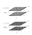
- FIG. 21A shows a configuration in which two rectangular flat plates 20a and 20b made of metal in which through holes 21 having a predetermined diameter are formed are opposed to each other, and the through holes are formed.
- FIG. 21B shows a configuration in which two rectangular flat plates 30a and 30b that are not made of metal are arranged to face each other.
- a waveguide is formed by two rectangular flat plates 30a and 30b shown in FIG. 21 (b), and an electric field component E is in the x-axis direction and a magnetic field component H is in the y-axis direction.
- a waveguide is formed by two rectangular flat plates 20a and 20b formed by arranging the through holes 21 having a predetermined diameter shown in FIG. 21A vertically and horizontally, and an electric field component is formed in the waveguide.
- the wavelength of the incident wave propagating through the waveguide composed of the flat plates 20a and 20b is the wavelength. ⁇ a.
- the through hole 21 is provided, ⁇ o ⁇ a, and the wavelength becomes longer in the waveguide.
- the rate of increasing the wavelength decreases, and ⁇ a ⁇ g and ⁇ o ⁇ a ⁇ g.
- the two central flat plates 15a and 15b are formed with through holes 15 having a radius r5 of the maximum diameter in the central portion, and the radius having the second largest diameter on both sides thereof.
- a through hole 14 of r4 is formed, a through hole 13 having a radius r3 having the third largest diameter is formed on both sides thereof, and a through hole 12 having a radius r2 having the fourth largest diameter is formed on both sides thereof.
- a through hole 11 having the smallest radius r1 is formed.
- the fourth intermediate flat plates 14a and 14b adjacent to the upper and lower sides of the central flat plates 15a and 15b are formed with through holes 14 having a radius r4 having the second largest diameter in the central portion, and third on both sides thereof.
- a through hole 13 having a radius r3 having a large diameter is formed, a through hole 12 having a radius r2 having the fourth largest diameter is formed on both sides thereof, and a through hole 11 having a radius r1 having the smallest diameter is formed on both sides thereof.
- the third intermediate flat plates 13a and 13b adjacent to the upper and lower sides of the fourth intermediate flat plates 14a and 14b are formed with through holes 13 having a radius r3 having the third largest diameter at the center, on both sides thereof.
- a through hole 12 having a radius r2 having the fourth largest diameter is formed, and a through hole 11 having a radius r1 having the smallest diameter is formed on both sides thereof.
- a through hole 13 having a radius r3 having the third largest diameter is formed in a large region of the central portion.
- a through hole 12 having a radius r2 having the fourth largest diameter is formed on both sides thereof, and a through hole 11 having a radius r1 having the smallest diameter is formed on both sides thereof.
- a through hole 12 having a radius r2 having the fourth largest diameter is formed in a wide region at the center.
- the through holes 11 having the smallest radius r1 are formed on both sides.
- no through hole is formed in the uppermost flat plate 10a and the lowermost flat plate 10b adjacent to the upper and lower sides of the first intermediate flat plates 11a and 11b.
- each adjacent flat plate forms a waveguide
- a through hole having a large diameter is formed in the central portion of the central flat plates 15a and 15b. Therefore, the wavelength of the incident wave propagating through the central portion becomes a wavelength close to the free space wavelength, and the diameter of the through hole formed in the flat plate gradually decreases as it moves away from the central portion in the vertical and horizontal directions, The wavelength of the incident wave that propagates away from the center in the vertical and horizontal directions gradually becomes longer than the free space wavelength. Thereby, the incident wave is focused and acts as a lens.
- FIG. 9A shows the dimensions of the model 1 parameters of the metal plate lens 1 according to the present invention
- FIG. 9B shows the dimensions of the radii r1 to r5 of the through holes 11 to 15 formed in the flat plates 10a to 15b.
- the design frequency f is 0.5 THz
- the wavelength ⁇ of the free space of the design frequency f is 600 ⁇ m.
- each flat plate 10a to 15b in the optical axis (z-axis) direction of the metal plate lens 1 of the model 1 according to the present invention is about 2.1 mm (about 3.5 ⁇ ), and each flat plate 10a in the x-axis direction.
- the horizontal width w of ⁇ 15b is about 4.2 mm (about 7.0 ⁇ ), and the height h in the y-axis direction of the metal plate lens 1 is about 3.77 mm (about 6.77 mm) as shown in FIG.
- the distances d1 to d6 between the flat plates 10a to 15b are set to a uniform distance d of about 0.310 mm (about 0.52 ⁇ ), and the thickness t of each flat plate 10a to 15b is about 30 ⁇ m ( About 0.05 ⁇ ).
- the radius r1 of the through hole 11 formed in each of the flat plates 11a to 15b is about 15 ⁇ m (about 0.025 ⁇ ), and the radius r2 of the through hole 12 formed in each of the flat plates 12a to 15b is about 50 ⁇ m (
- the radius r3 of the through hole 13 formed in each of the flat plates 13a to 15b is about 70 ⁇ m (about 0.12 ⁇ ), and the through hole 14 formed in each of the flat plates 14a to 15b has a radius r3.
- the radius r4 is about 80 ⁇ m (about 0.13 ⁇ )
- the radius r5 of the through hole 15 formed in the central flat plates 15a and 15b is about 85 ⁇ m (about 0.14 ⁇ ).
- an interval s between the x direction and the z direction for forming the through holes 11 to 15 is set to about 0.175 mm (about 0.29 ⁇ ).
- the analysis result of the metal plate lens 1 of the model 1 according to the present invention having the dimensions shown in FIGS. 9A and 9B is shown in FIG. 10, and the electric field strength distribution on the optical axis is shown in FIG. .
- the incident wave incident on the metal plate lens 1 of the model 1 according to the present invention propagates in the z-axis direction in which the electric field component E is in the x-axis direction and the magnetic field component H is in the y-axis direction.
- the incident wave is a TE mode, and its frequency is 0.5 THz.
- the waveguide is formed by two adjacent flat plates in the flat plates 10a to 15b, and the interval d between the flat plates is about 0.310 mm (about 0.52 ⁇ ).
- the maximum value of the electric field intensity is about 0.86 mm (about 1.4 ⁇ ) from the rear end of the metal plate lens 1.
- the electric field intensity at the condensing position is about 4.0 times the incident wave.
- the radii r1 to r3 of the through holes 11 to 13 are changed as shown in FIG. 9B, so that the metal plate on the central optical axis (z axis).
- the position of about 0.86 mm (about 1.4 ⁇ ) is about 0.31 mm away from the rear end of the lens 1 and becomes a focal point for three-dimensional focusing, and the electric field strength against incident waves is improved by 4.0 times
- FIG. 11B shows the electric field intensity distribution in the x direction at this focal position
- FIG. 11C shows the electric field intensity distribution in the y direction at this focal position.
- the incident wave is condensed three-dimensionally at the focal position.
- the metal plate lens 1 of the model 1 acts as a lens.
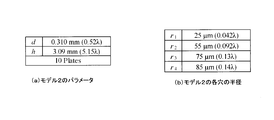
- FIG. 12A shows the dimensions of the model 2 parameters of the metal plate lens 1 according to the present invention
- FIG. 12B shows the dimensions of the radii r1 to r4 of the through holes 11 to 14 formed in the flat plates 10a to 14b. ).
- each flat plate 10a to 14b in the optical axis (z-axis) direction of the metal plate lens 1 of the model 2 according to the present invention is about 2.1 mm (about 3.5 ⁇ ), and each flat plate 10a in the x-axis direction.
- the horizontal width w of .about.14b is about 4.2 mm (about 7.0 ⁇ ), and the height h in the y-axis direction of the metal plate lens 1 is about 3.09 mm (about 5.9 mm) as shown in FIG.
- the distances d2 to d6 between the flat plates 10a to 14b are set to a uniform distance d of about 0.310 mm (about 0.52 ⁇ ), and the thickness t of each flat plate 10a to 14b is about 30 ⁇ m ( About 0.05 ⁇ ).
- the radius r1 of the through hole 11 formed in each of the flat plates 11a to 14b is about 25 ⁇ m (about 0.042 ⁇ ), and the radius r2 of the through hole 12 formed in each of the flat plates 12a to 14b is about 55 ⁇ m (
- the radius r3 of the through hole 13 formed in each of the flat plates 13a to 14b is about 75 ⁇ m (about 0.13 ⁇ ), and is formed in the fourth intermediate flat plates 14a and 14b.
- the radius r4 of the through hole 14 is about 85 ⁇ m (about 0.14 ⁇ ).
- an interval s between the x direction and the z direction in which the through holes 11 to 14 are formed is about 0.175 mm (about 0.29 ⁇ ).
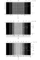
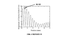
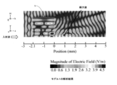
- the analysis result of the metal plate lens 1 of the model 2 according to the present invention having the dimensions shown in FIGS. 12A and 12B is shown in FIG. 13, and the electric field intensity distribution on the optical axis is shown in FIG.
- the incident wave incident on the metal plate lens 1 of the model 2 according to the present invention propagates in the z-axis direction in which the electric field component E is in the x-axis direction and the magnetic field component H is in the y-axis direction.
- the incident wave is a TE mode, and its frequency is 0.5 THz.
- the waveguide is formed by two adjacent flat plates in the flat plates 10a to 14b, and the interval d between the flat plates is about 0.310 mm (about 0.52 ⁇ ).
- the maximum value of the electric field intensity is about 0.19 mm (about 0.32 ⁇ ) from the rear end of the metal plate lens 1.
- the electric field intensity at the condensing position is about 4.4 times the incident wave.
- the central flat plates 15a and 15b are omitted, the number of flat plates is ten, and the dimensions of the radii r1 to r4 of the through holes 11 to 14 are changed.
- the position of about 0.19 mm (about 0.32 ⁇ ) is three-dimensionally gathered on the central optical axis (z-axis), being about 0.36 mm (about 0.60 ⁇ ) from the rear end of the metal plate lens 1.
- FIG. 14B shows the electric field intensity distribution in the x direction at this focal position
- FIG. 14C shows the electric field intensity distribution in the y direction at this focal position.
- the incident wave is condensed three-dimensionally at the focal position.
- the metal plate lens 1 of the model 2 acts as a lens.
- model 1 and model 2 of the metal plate lens 1 are three-dimensionally condensed. Therefore, it is possible to obtain a light collecting effect as a lens by using the structure of the metal plate lens 1 shown in FIG. Further, when comparing the electric field strength distribution on the optical axis shown in FIGS. 7, 11A, and 14A, the refractive index of the model 1 is longer than that of the reference model. You can see that it is approaching 1. Regarding model 2, since the focal point is formed at a position of about 0.19 mm (about 0.32 ⁇ ), the refractive index is considered to be close to zero.
- the refractive index of the metal plate lens 1 can be controlled by changing the radii r1 to r5 of the through holes 11 to 15 formed in the flat plates 11a to 15b. It turns out that it is possible.
- FIG. 15 shows the parameter dimensions of the model 3 of the metal plate lens 1 according to the present invention.
- the design frequency f is 0.5 THz
- the wavelength ⁇ of the free space of the design frequency f is 600 ⁇ m.
- the dimensions of the radii r1 to r5 of the through holes 11 to 15 formed in the flat plates 10a to 15b are the same as those of the metal plate lens 1 of the reference model.
- each flat plate 10a to 15b in the optical axis (z-axis) direction of the metal plate lens 1 of the model 3 according to the present invention is about 2.1 mm (about 3.5 ⁇ ), and each flat plate 10a in the x-axis direction.
- the horizontal width w of ⁇ 15b is about 4.2 mm (about 7.0 ⁇ ), and the height h in the y-axis direction of the metal plate lens 1 is about 4.21 mm (about 7.02 ⁇ ) as shown in FIG.
- the distances d1 to d6 between the flat plates 10a to 15b are set to a uniform distance d of about 0.350 mm (about 0.58 ⁇ ), and the thickness t of each flat plate 10a to 15b is about 30 ⁇ m (about 0.1 mm). 05 ⁇ ). Further, an interval s between the x direction and the z direction for forming the through holes 11 to 15 is set to about 0.175 mm (about 0.29 ⁇ ).
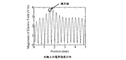
- the analysis result of the metal plate lens 1 of the model 3 according to the present invention having the dimensions shown in FIG. 15 is shown in FIG. 16, and the electric field intensity distribution on the optical axis is shown in FIG.
- the incident wave incident on the metal plate lens 1 of the model 3 according to the present invention propagates in the z-axis direction in which the electric field component E is in the x-axis direction and the magnetic field component H is in the y-axis direction.
- the incident wave is a TE mode, and its frequency is 0.5 THz.
- the waveguide is formed by two adjacent flat plates in the flat plates 10a to 15b, and the interval d between the flat plates is about 0.310 mm (about 0.52 ⁇ ).
- the maximum value of the electric field intensity is about 1.54 mm (about 2.6 ⁇ ) from the rear end of the metal plate lens 1, and the light is condensed.
- the electric field strength at the position is about 3.7 times the incident wave.
- the metal plate lens 1 of the model 3 has a condensing position farther by about 0.99 mm (about 1.7 ⁇ ) than the metal plate lens 1 of the reference model, but the electric field strength is almost the same. Therefore, if the dimension of the distance d in the flat plates 10a to 15b is increased, the focal length becomes longer. Therefore, it is considered that the refractive index is close to 1, and it is also possible to change the distance d in the flat plates 10a to 15b. The refractive index can be changed. When the electric field intensity distribution on the optical axis shown in FIGS. 7 and 17 is compared, the electric field intensity is approximately the same, but it can be confirmed that the focal length is longer in Model 3.
- the metal plate lens 1 according to the present invention can control the refractive index by changing the distance d between the flat plates 10a to 15b.
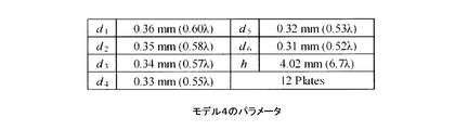
- FIG. 18 shows the parameter dimensions of the model 4 of the metal plate lens 1 according to the present invention.
- the design frequency f is 0.5 THz
- the wavelength ⁇ of the free space of the design frequency f is 600 ⁇ m.
- the dimensions of the radii r1 to r5 of the through holes 11 to 15 formed in the flat plates 10a to 15b are the same as those of the metal plate lens 1 of the reference model.
- each flat plate 10a to 15b in the optical axis (z-axis) direction of the metal plate lens 1 of the model 4 according to the present invention is about 2.1 mm (about 3.5 ⁇ ), and each flat plate 10a in the x-axis direction.
- the lateral width w of ⁇ 15b is about 4.2 mm (about 7.0 ⁇ ).
- the height h in the y-axis direction of the metal plate lens 1 is about 4.02 mm (about 6.7 ⁇ )
- the distance d1 between the central flat plate 15a and the central flat plate 15b is about
- the distance d2 between the central flat plates 15a and 15b and the fourth intermediate flat plates 14a and 14b is set to about 0.35 mm (about 0.58 ⁇ ).
- the distance d3 between the partial flat plates 14a, 14d and the third intermediate flat plates 13a, 13b is about 0.34 mm (about 0.57 ⁇ ), and the third intermediate flat plates 13a, 13b and the second intermediate flat plate 12a , 12b is about 0.33 mm (about 0.55 ⁇ ), and the distance d5 between the second intermediate flat plates 12a, 12b and the first intermediate flat plates 11a, 11b is about 0.32 mm (about 0.53 ⁇ ) and the first intermediate flat plates 11a, 11
- the spacing d6 between the uppermost flat 10a or bottom flat 10b is about 0.31 mm (about 0.52 ⁇ ).
- the thickness t of each of the flat plates 10a to 15b is about 30 ⁇ m (about 0.05 ⁇ ). Further, an interval s between the x direction and the z direction for forming the through holes 11 to 15 is set to about 0.175 mm (about 0.29 ⁇ ).
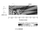
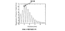
- the analysis result of the model 4 metal plate lens 1 according to the present invention having the dimensions shown in FIG. 18 is shown in FIG. 19, and the electric field strength distribution on the optical axis is shown in FIG.
- the incident wave incident on the metal plate lens 1 of the model 4 according to the present invention propagates in the z-axis direction in which the electric field component E is in the x-axis direction and the magnetic field component H is in the y-axis direction.
- the incident wave is a TE mode, and its frequency is 0.5 THz.
- the waveguide is formed by two adjacent flat plates in the flat plates 10a to 15b, and the distance d between the flat plates is about 0.310 mm (about 0.52 ⁇ ) or more.
- the frequency is about 0.48 THz or less lower than 0.5 THz, and an incident wave of 0.5 THz can be propagated.
- the maximum value of the electric field intensity is about 1.02 mm (about 1.7 ⁇ ) from the rear end of the metal plate lens 1, and the light is condensed.
- the electric field strength at the position is about 6.2 times the incident wave.
- the interval between the flat plates in the center is increased, and the interval is decreased as it goes up and down.
- the phase difference between the electromagnetic wave passing through the central part and the uppermost part or the lowermost part of the metal plate lens 1 becomes large. It becomes possible to obtain higher electric field strength than the model.
- the analysis of the metal plate lens 1 shown in FIGS. 6, 10, 13, 16, and 19 was performed using HFSS manufactured by ANSYS as in the case of the concave lens. Similarly to the concave lens, the analysis method uses the image principle to perform analysis using a 1 ⁇ 4 model with a small analysis capacity.
- the metal plate lens according to the present invention described above can be applied to a region having a short wavelength such as a terahertz wave without adopting a structure that realizes a negative refractive index, but is limited to application to a terahertz wave. Instead, it can be applied to lenses in other frequency bands.
- the physical dimensions of each part may be changed in accordance with the center wavelength of the frequency band to be applied so as to match the dimension of the electrical length expressed by ⁇ (wavelength).
- ⁇ wavelength
- the layers it is practical to support the flat plates with a dielectric support substrate so that the intervals between the flat plates are maintained at a predetermined interval.
- the physical dimensions of each part are adjusted so as to match the dimension of the electrical length represented by ⁇ (wavelength) described above in consideration of the wavelength shortening ratio. Is preferably changed.
- the diameter of the through hole formed in each flat plate constituting the metal plate lens according to the present invention is gradually reduced from the central portion toward the top, bottom, left and right. The diameter may be made gradually smaller from the center to the top and bottom, and the diameter of the through hole may be the same from the center to the left and right.
- the shape of the through hole is circular, the shape of the through hole is not limited to this, and the shape of the through hole is triangular, quadrangular, polygonal, or elliptical. Just make it smaller. And when making the shape of a through-hole into a triangle, a square, or a polygon, since the through-hole is created by processing with a drill etc., the corner
- the above-described dimensions of the reference model or model 4 in the metal plate lens of the present invention are merely examples, and are not limited to these dimensions.
- the shape seen from the front of the metal plate lens of this invention was made into the rectangular shape, it is not restricted to this, It can be set as circular or a polygon.
- Impedance matching can be achieved by adding a split ring resonator to the input side of the metal plate lens 1.
- the split ring resonator includes a circular ring-shaped first split ring in which a cut portion is formed, an outer diameter smaller than that of the first split ring, and is disposed substantially concentrically and within the same plane, with a cut portion on the opposite side. It is comprised from the 2nd division
- impedance matching can be achieved by controlling the permeability by adjusting the diameter and width of the first split ring and the second split ring.
- 1 metal plate lens 10a uppermost flat plate, 10b lowermost flat plate, 11 through hole, 11a, 11b first intermediate flat plate, 12 through hole, 12a, 12b second intermediate flat plate, 13 through hole, 13a, 13b Third intermediate flat plate, 14 through holes, 14a, 14b Fourth intermediate flat plate, 15 through holes, 15a, 15b central flat plate, 20a, 20b, 30a, 30b flat plate, 21 through holes
Landscapes
- Aerials With Secondary Devices (AREA)
- Waveguide Connection Structure (AREA)
Abstract
Le problème à résoudre dans le cadre de la présente invention consiste à fournir une lentille à plaques métalliques qui peut être facilement créée même pour des bandes haute fréquence. La solution proposée consiste en des plaques métalliques (10a à 15b) qui sont disposées de façon parallèle au plan x - z de sorte à être empilées selon des intervalles prédéterminés, l'axe z étant l'axe central et les axes qui sont orthogonaux à l'axe z, étant l'axe x et l'axe y. Les plaques (11a à 15b) autres que la plaque la plus haute (10a) et la plaque la plus basse (10b) comportant une pluralité de trous traversants qui sont formés dans ces dernières. Dans ce cas, les plaques centrales (15a, 15b) comportent des trous traversants formés dans ces dernières qui présentent des premiers diamètres et les plaques intermédiaires (11a à 14b), qui sont disposées entre la plaque centrale (15a) et la plaque la plus haute (10a) et entre la plaque centrale (15b) et la plaque la plus basse (10b), comportent des trous traversants formés dans ces dernières qui présentent des seconds diamètres qui sont plus petits que les premiers diamètres. Les seconds diamètres des trous traversants formés dans les plaques intermédiaires qui sont disposées à une certaine distance des plaques centrales (15a, 15b), sont réalisés de sorte à être plus petits que les seconds diamètres des trous traversants formés dans les plaques intermédiaires qui sont disposées de sorte à être plus près des plaques centrales (15a, 15b).
Priority Applications (1)
| Application Number | Priority Date | Filing Date | Title |
|---|---|---|---|
| US14/776,004 US9799960B2 (en) | 2013-03-15 | 2014-03-14 | Metal plate lens comprising multiple metallic plates with through holes of different sizes |
Applications Claiming Priority (2)
| Application Number | Priority Date | Filing Date | Title |
|---|---|---|---|
| JP2013-053575 | 2013-03-15 | ||
| JP2013053575A JP6041349B2 (ja) | 2013-03-15 | 2013-03-15 | メタルプレートレンズ |
Publications (1)
| Publication Number | Publication Date |
|---|---|
| WO2014142294A1 true WO2014142294A1 (fr) | 2014-09-18 |
Family
ID=51536942
Family Applications (1)
| Application Number | Title | Priority Date | Filing Date |
|---|---|---|---|
| PCT/JP2014/056836 Ceased WO2014142294A1 (fr) | 2013-03-15 | 2014-03-14 | Lentille à plaques métalliques |
Country Status (3)
| Country | Link |
|---|---|
| US (1) | US9799960B2 (fr) |
| JP (1) | JP6041349B2 (fr) |
| WO (1) | WO2014142294A1 (fr) |
Cited By (2)
| Publication number | Priority date | Publication date | Assignee | Title |
|---|---|---|---|---|
| CN106329051A (zh) * | 2016-09-28 | 2017-01-11 | 中国人民解放军国防科学技术大学 | 金属平板透镜 |
| WO2023189994A1 (fr) * | 2022-03-29 | 2023-10-05 | 富士フイルム株式会社 | Méta-lentille |
Families Citing this family (4)
| Publication number | Priority date | Publication date | Assignee | Title |
|---|---|---|---|---|
| CN105842761B (zh) * | 2016-06-08 | 2018-02-27 | 重庆邮电大学 | 井字堆叠型太赫兹波光学聚焦透镜 |
| CN106896429B (zh) * | 2017-04-19 | 2018-05-18 | 中国计量大学 | 一种基于金属平板的太赫兹透镜 |
| TWI794770B (zh) | 2021-03-15 | 2023-03-01 | 明泰科技股份有限公司 | 調整天線場型的天線罩 |
| TWI827091B (zh) * | 2022-06-09 | 2023-12-21 | 明泰科技股份有限公司 | 調整天線場型的天線罩 |
Citations (3)
| Publication number | Priority date | Publication date | Assignee | Title |
|---|---|---|---|---|
| JPS622954A (ja) * | 1985-06-29 | 1987-01-08 | 菊地 眞 | 加温療法用アプリケ−タ |
| JP2006074551A (ja) * | 2004-09-03 | 2006-03-16 | Nippon Hoso Kyokai <Nhk> | 電波レンズ |
| JP2010213021A (ja) * | 2009-03-11 | 2010-09-24 | Shiga Prefecture | 電波レンズ |
Family Cites Families (2)
| Publication number | Priority date | Publication date | Assignee | Title |
|---|---|---|---|---|
| EP2933225A1 (fr) | 2004-07-23 | 2015-10-21 | The Regents of The University of California | Méta-matériaux |
| US8421550B2 (en) * | 2011-03-18 | 2013-04-16 | Kuang-Chi Institute Of Advanced Technology | Impedance matching component and hybrid wave-absorbing material |
-
2013
- 2013-03-15 JP JP2013053575A patent/JP6041349B2/ja not_active Expired - Fee Related
-
2014
- 2014-03-14 WO PCT/JP2014/056836 patent/WO2014142294A1/fr not_active Ceased
- 2014-03-14 US US14/776,004 patent/US9799960B2/en not_active Expired - Fee Related
Patent Citations (3)
| Publication number | Priority date | Publication date | Assignee | Title |
|---|---|---|---|---|
| JPS622954A (ja) * | 1985-06-29 | 1987-01-08 | 菊地 眞 | 加温療法用アプリケ−タ |
| JP2006074551A (ja) * | 2004-09-03 | 2006-03-16 | Nippon Hoso Kyokai <Nhk> | 電波レンズ |
| JP2010213021A (ja) * | 2009-03-11 | 2010-09-24 | Shiga Prefecture | 電波レンズ |
Cited By (4)
| Publication number | Priority date | Publication date | Assignee | Title |
|---|---|---|---|---|
| CN106329051A (zh) * | 2016-09-28 | 2017-01-11 | 中国人民解放军国防科学技术大学 | 金属平板透镜 |
| CN106329051B (zh) * | 2016-09-28 | 2018-10-19 | 中国人民解放军国防科学技术大学 | 金属平板透镜 |
| WO2023189994A1 (fr) * | 2022-03-29 | 2023-10-05 | 富士フイルム株式会社 | Méta-lentille |
| US12620686B2 (en) | 2022-03-29 | 2026-05-05 | Fujifilm Corporation | Metalens |
Also Published As
| Publication number | Publication date |
|---|---|
| JP2014179876A (ja) | 2014-09-25 |
| JP6041349B2 (ja) | 2016-12-07 |
| US20160028142A1 (en) | 2016-01-28 |
| US9799960B2 (en) | 2017-10-24 |
Similar Documents
| Publication | Publication Date | Title |
|---|---|---|
| JP6112708B2 (ja) | メタマテリアル | |
| JP6041349B2 (ja) | メタルプレートレンズ | |
| EP3676642B1 (fr) | Dispositif optique capable de fournir au moins deux fonctions optiques différentes | |
| US8300294B2 (en) | Planar gradient index optical metamaterials | |
| EP2688380B1 (fr) | Composant d'adaptation d'impédance et matériau hybride absorbant les ondes | |
| US12174512B2 (en) | Device for forming an outgoing electromagnetic wave from an incident electromagnetic wave | |
| US20190074595A1 (en) | Sheet-type metamaterial and sheet-type lens | |
| CN102480061B (zh) | 基于超材料的天线和超材料面板的工作波长的生成方法 | |
| CN104377452B (zh) | 一种基于人工电磁表面的纯介质电磁透镜的设计方法 | |
| US10686255B2 (en) | Sheet-type metamaterial and sheet-type lens | |
| JP5904490B2 (ja) | 人工誘電体レンズ | |
| KR20160099745A (ko) | 근사적 비 분산 메타물질에 의한 음향 렌즈 | |
| US8729511B2 (en) | Electromagnetic wave beam splitter | |
| WO2021058672A1 (fr) | Lentille en métamatériau à gradient d'indice pour rayonnement térahertz | |
| CN214201830U (zh) | 二维封闭式表面波光子晶体结构 | |
| Abujetas et al. | Photonic band structure and effective medium properties of doubly-resonant core-shell metallo-dielectric nanowire arrays: low-loss, isotropic optical negative-index behavior | |
| Jiang et al. | Spatial transformation-enabled electromagnetic devices: from radio frequencies to optical wavelengths | |
| JP6333122B2 (ja) | 金属スリットアレー | |
| Vasilantonakis et al. | Designing high-transmission and wide angle all-dielectric flat metasurfaces at telecom wavelengths | |
| Liu et al. | High-Efficient and Polarization-Insensitive Metalens Using Sub-Wavelength Circular Slot Elements | |
| Anwar et al. | Fast-light propagation in a zero-index photonic crystal waveguide with photonic bandgap claddings | |
| Jain et al. | Field transformation approach to designing lenses | |
| JP2006178209A (ja) | 導波路 | |
| Wongkasem et al. | Multifocal Optical Meta-Lenses | |
| CN113922099A (zh) | 利用修正等效介质理论实现二维多层龙伯透镜离散化的方法 |
Legal Events
| Date | Code | Title | Description |
|---|---|---|---|
| 121 | Ep: the epo has been informed by wipo that ep was designated in this application |
Ref document number: 14765691 Country of ref document: EP Kind code of ref document: A1 |
|
| WWE | Wipo information: entry into national phase |
Ref document number: 14776004 Country of ref document: US |
|
| NENP | Non-entry into the national phase |
Ref country code: DE |
|
| 122 | Ep: pct application non-entry in european phase |
Ref document number: 14765691 Country of ref document: EP Kind code of ref document: A1 |