WO2014147675A1 - Dispositif cpap - Google Patents
Dispositif cpap Download PDFInfo
- Publication number
- WO2014147675A1 WO2014147675A1 PCT/JP2013/005827 JP2013005827W WO2014147675A1 WO 2014147675 A1 WO2014147675 A1 WO 2014147675A1 JP 2013005827 W JP2013005827 W JP 2013005827W WO 2014147675 A1 WO2014147675 A1 WO 2014147675A1
- Authority
- WO
- WIPO (PCT)
- Prior art keywords
- housing
- casing
- main body
- air
- attachment
- Prior art date
- Legal status (The legal status is an assumption and is not a legal conclusion. Google has not performed a legal analysis and makes no representation as to the accuracy of the status listed.)
- Ceased
Links
Images


Classifications
-
- A—HUMAN NECESSITIES
- A61—MEDICAL OR VETERINARY SCIENCE; HYGIENE
- A61M—DEVICES FOR INTRODUCING MEDIA INTO, OR ONTO, THE BODY; DEVICES FOR TRANSDUCING BODY MEDIA OR FOR TAKING MEDIA FROM THE BODY; DEVICES FOR PRODUCING OR ENDING SLEEP OR STUPOR
- A61M16/00—Devices for influencing the respiratory system of patients by gas treatment, e.g. ventilators; Tracheal tubes
- A61M16/0057—Pumps therefor
- A61M16/0066—Blowers or centrifugal pumps
- A61M16/0069—Blowers or centrifugal pumps the speed thereof being controlled by respiratory parameters, e.g. by inhalation
-
- F—MECHANICAL ENGINEERING; LIGHTING; HEATING; WEAPONS; BLASTING
- F04—POSITIVE - DISPLACEMENT MACHINES FOR LIQUIDS; PUMPS FOR LIQUIDS OR ELASTIC FLUIDS
- F04D—NON-POSITIVE-DISPLACEMENT PUMPS
- F04D29/00—Details, component parts, or accessories
- F04D29/40—Casings; Connections of working fluid
- F04D29/42—Casings; Connections of working fluid for radial or helico-centrifugal pumps
- F04D29/4206—Casings; Connections of working fluid for radial or helico-centrifugal pumps especially adapted for elastic fluid pumps
- F04D29/4226—Fan casings
-
- F—MECHANICAL ENGINEERING; LIGHTING; HEATING; WEAPONS; BLASTING
- F04—POSITIVE - DISPLACEMENT MACHINES FOR LIQUIDS; PUMPS FOR LIQUIDS OR ELASTIC FLUIDS
- F04D—NON-POSITIVE-DISPLACEMENT PUMPS
- F04D29/00—Details, component parts, or accessories
- F04D29/60—Mounting; Assembling; Disassembling
- F04D29/62—Mounting; Assembling; Disassembling of radial or helico-centrifugal pumps
- F04D29/624—Mounting; Assembling; Disassembling of radial or helico-centrifugal pumps especially adapted for elastic fluid pumps
- F04D29/626—Mounting or removal of fans
-
- A—HUMAN NECESSITIES
- A61—MEDICAL OR VETERINARY SCIENCE; HYGIENE
- A61M—DEVICES FOR INTRODUCING MEDIA INTO, OR ONTO, THE BODY; DEVICES FOR TRANSDUCING BODY MEDIA OR FOR TAKING MEDIA FROM THE BODY; DEVICES FOR PRODUCING OR ENDING SLEEP OR STUPOR
- A61M16/00—Devices for influencing the respiratory system of patients by gas treatment, e.g. ventilators; Tracheal tubes
- A61M16/06—Respiratory or anaesthetic masks
- A61M16/0605—Means for improving the adaptation of the mask to the patient
- A61M16/0633—Means for improving the adaptation of the mask to the patient with forehead support
-
- A—HUMAN NECESSITIES
- A61—MEDICAL OR VETERINARY SCIENCE; HYGIENE
- A61M—DEVICES FOR INTRODUCING MEDIA INTO, OR ONTO, THE BODY; DEVICES FOR TRANSDUCING BODY MEDIA OR FOR TAKING MEDIA FROM THE BODY; DEVICES FOR PRODUCING OR ENDING SLEEP OR STUPOR
- A61M16/00—Devices for influencing the respiratory system of patients by gas treatment, e.g. ventilators; Tracheal tubes
- A61M16/0003—Accessories therefor, e.g. sensors, vibrators, negative pressure
- A61M2016/0027—Accessories therefor, e.g. sensors, vibrators, negative pressure pressure meter
-
- A—HUMAN NECESSITIES
- A61—MEDICAL OR VETERINARY SCIENCE; HYGIENE
- A61M—DEVICES FOR INTRODUCING MEDIA INTO, OR ONTO, THE BODY; DEVICES FOR TRANSDUCING BODY MEDIA OR FOR TAKING MEDIA FROM THE BODY; DEVICES FOR PRODUCING OR ENDING SLEEP OR STUPOR
- A61M16/00—Devices for influencing the respiratory system of patients by gas treatment, e.g. ventilators; Tracheal tubes
- A61M16/0003—Accessories therefor, e.g. sensors, vibrators, negative pressure
- A61M2016/003—Accessories therefor, e.g. sensors, vibrators, negative pressure with a flowmeter
- A61M2016/0033—Accessories therefor, e.g. sensors, vibrators, negative pressure with a flowmeter electrical
- A61M2016/0039—Accessories therefor, e.g. sensors, vibrators, negative pressure with a flowmeter electrical in the inspiratory circuit
-
- A—HUMAN NECESSITIES
- A61—MEDICAL OR VETERINARY SCIENCE; HYGIENE
- A61M—DEVICES FOR INTRODUCING MEDIA INTO, OR ONTO, THE BODY; DEVICES FOR TRANSDUCING BODY MEDIA OR FOR TAKING MEDIA FROM THE BODY; DEVICES FOR PRODUCING OR ENDING SLEEP OR STUPOR
- A61M2205/00—General characteristics of the apparatus
- A61M2205/42—Reducing noise
-
- A—HUMAN NECESSITIES
- A61—MEDICAL OR VETERINARY SCIENCE; HYGIENE
- A61M—DEVICES FOR INTRODUCING MEDIA INTO, OR ONTO, THE BODY; DEVICES FOR TRANSDUCING BODY MEDIA OR FOR TAKING MEDIA FROM THE BODY; DEVICES FOR PRODUCING OR ENDING SLEEP OR STUPOR
- A61M2205/00—General characteristics of the apparatus
- A61M2205/50—General characteristics of the apparatus with microprocessors or computers
- A61M2205/502—User interfaces, e.g. screens or keyboards
-
- A—HUMAN NECESSITIES
- A61—MEDICAL OR VETERINARY SCIENCE; HYGIENE
- A61M—DEVICES FOR INTRODUCING MEDIA INTO, OR ONTO, THE BODY; DEVICES FOR TRANSDUCING BODY MEDIA OR FOR TAKING MEDIA FROM THE BODY; DEVICES FOR PRODUCING OR ENDING SLEEP OR STUPOR
- A61M2205/00—General characteristics of the apparatus
- A61M2205/82—Internal energy supply devices
- A61M2205/8206—Internal energy supply devices battery-operated
-
- F—MECHANICAL ENGINEERING; LIGHTING; HEATING; WEAPONS; BLASTING
- F05—INDEXING SCHEMES RELATING TO ENGINES OR PUMPS IN VARIOUS SUBCLASSES OF CLASSES F01-F04
- F05D—INDEXING SCHEME FOR ASPECTS RELATING TO NON-POSITIVE-DISPLACEMENT MACHINES OR ENGINES, GAS-TURBINES OR JET-PROPULSION PLANTS
- F05D2260/00—Function
- F05D2260/30—Retaining components in desired mutual position
- F05D2260/36—Retaining components in desired mutual position by a form fit connection, e.g. by interlocking
Definitions
- the present invention relates to a CPAP (Continuous Positive Airway Pressure) device used for the treatment of sleep apnea syndrome.
- CPAP Continuous Positive Airway Pressure
- a CPAP device For the treatment of sleep apnea syndrome, a CPAP device is used which applies a mask to the face and forcibly sends air into the airway with a fan.
- a main unit with a built-in fan, control unit, etc. is placed at a position away from the human body, and the hose is connected between the main unit and the mask addressed to the face with a hose of about 1.5 m.
- a structure in which air is sent via the air is used.
- Various types of masks have been developed and marketed, and patients select and use a mask that suits their face shape and taste.
- the main body device has a volume of about 140 ⁇ 180 ⁇ 100 mm, and is inconvenient to carry.
- the treatment method that has a problem and must be used continuously every day, it is one of the treatment devices that are often not used continuously because it is inconvenient for the patient.
- Patent Document 1 proposes several structures in order to obtain a CPAP device that is easy to handle.
- Patent Document 1 discloses a structure in which a fan is placed on the front face of a face integrally with a mask.
- this Patent Document 1 shows a configuration in which a device incorporating a fan is attached to a patient's body, specifically a waist belt or arm, and the device and a mask attached to the face are connected by a hose.
- a hose that is considerably shorter than the 1.5 m long hose used in the conventional CPAP apparatus is sufficient.
- the burden on the patient is lighter than the configuration in which the device and the hose are integrally mounted on the face.
- an object of the present invention is to provide a CPAP device that combines the convenience of handling and the alleviation of the burden on the patient at a high level.
- the CPAP device of the present invention that achieves the above object is as follows.
- the lower part of the case and the shape of the upper part of the case that protrudes forward from the lower part of the case make the thickness dimension in the front-rear direction larger than the lower part of the case.
- a main body housing having an upper portion of the housing formed with an air outlet; It has a battery housing chamber provided in the lower part of the casing, and a device main body provided with a fan that is built in the upper part of the casing and sucks air from the air inlet and blows out air from the air outlet.
- the CPAP device of the present invention is provided with a device body that is particularly suitable for being used by being inserted into a patient's breast pocket. That is, the lower part of the housing is inserted into the breast pocket, and the upper part of the housing is used in a state of protruding from the breast pocket.
- the upper part of the casing has a shape protruding forward from the lower part of the casing, and is thicker in the front-rear direction than the lower part of the casing. For this reason, when the lower part of the casing is inserted into the breast pocket, the upper part of the casing is caught by the edge of the entrance of the breast pocket and protrudes from the breast pocket. An air intake is provided in the upper part of the housing that protrudes from the breast pocket. For this reason, the flow path of the air for sending to a mask is ensured.
- a heavy battery is accommodated in the lower part of the casing.
- the CPAP device of the present invention has a shape and structure suitable for use by being inserted into a patient's breast pocket, and is easy to handle. Further, since the main body of the apparatus is away from the face, it is difficult for noise due to air inhalation and noise and vibration due to rotation of the fan to be transmitted, and the burden on the patient is reduced.
- An air outlet that is attached to the main body casing so as to face the front surface of the upper part of the casing and extends downward with a space from the front surface of the lower part of the casing;
- An attachment housing having an air inlet that is an intake port for the air sucked into the upper portion of the housing through the air outlet port and the air intake port, and the air flowed into the attachment housing from the air inlet port
- the lower housing can be inserted into the breast pocket even if the attachment is attached. Also, with the above-mentioned attachment, it can be configured so that the chest pocket is sandwiched between the lower housing inserted into the breast pocket and the attachment located in front of the chest pocket, so that the main body of the device will inadvertently come out of the chest. The risk of losing is reduced.
- the attachment in the case of a configuration including an attachment, the attachment includes a controller including an operator provided on the front surface of the attachment housing and a display screen, It is preferable that the apparatus main body includes a control circuit that controls rotation of the fan and display on the display screen in accordance with the operation content of the operation element.
- the attachment Since the attachment is located in front of the breast pocket, it is preferable to have a controller in that part.
- the display screen is preferably displayed in a vertically reversed display format.
- the display screen For patients wearing the device body in their breast pockets, they will look into the display screen from above. Thus, by displaying the display screen in a display format reversed upside down, the correct screen can be referred to in the vertical direction for the patient.
- the attachment is provided on the front surface of the attachment housing with an operation element and a display screen, and has a controller that can be lifted in a direction in which the upper portion is a hinge and the lower portion is separated from the front surface of the attachment housing. It is preferable.
- the lower part of the controller can be lifted to check the display screen and the operation element can be operated, which further improves the usability of the controller for the patient.
- the battery housing chamber provided in the lower portion of the housing is a battery housing chamber for housing the secondary battery, and the lower portion of the housing is detachable from the upper portion of the housing, It is preferable that the lower part of the housing includes a charging circuit that charges the secondary battery housed in the battery housing chamber with electric power generated by electromagnetic induction from the outside.
- the CPAP device needs to be used for a while until it wakes up after it is put on, and it is necessary to avoid the battery running out during that time.
- the battery housing chamber provided in the lower portion of the housing is a battery housing chamber for housing the secondary battery, and the lower portion of the housing is detachable with respect to the upper portion of the housing. If the charging circuit for charging the secondary battery housed in the battery housing chamber is provided at the lower part with the electric power generated by electromagnetic induction from the outside, the troublesome charging is reduced and the CPAP device is more convenient to use.
- the upper portion of the casing is protruded from the pocket of the clothes and the lower portion of the casing is accommodated in the pocket provided on the left and right side surfaces of the lower portion of the casing. It is preferable to further include a retaining mechanism for preventing the retaining of the retaining member.
- the CPAP device of the present invention is a CPAP device having a shape and structure convenient for use by inserting the device main body into the breast pocket.
- the CPAP device does not necessarily need to be inserted into the chest pocket. For example, when wearing clothes with a sleeve pocket, it may be inserted into the sleeve pocket, or may be used while being placed on the body without being inserted into the pocket.
- the CPAP device of the present invention it is possible to achieve a high level of compatibility between the convenience of handling and the relief of the burden on the patient.
- FIG. 3 It is the figure which showed the use condition of the CPAP apparatus of 1st Embodiment of this invention. It is the front view (A) and side view (B) of an apparatus main body. It is the front view (A) and side view which showed the state which attached the attachment of the 1st example to the apparatus main body. It is the front view (A) and side view (B) which showed the state which attached the attachment of the 2nd example different from the attachment shown in FIG. 3 to the apparatus main body.
- FIG. 7 is a cross-sectional view of the turbo fan in the direction indicated by arrow AA in FIG. 6.
- FIG. 1 is a diagram showing a usage state of the CPAP device according to the first embodiment of the present invention.
- the CPAP device 10 includes a device main body 20, a hose 30 connected to the device main body 20, and a mask 40.
- a mask suitable for the patient 1 is selected from a variety of commercially available types.
- the mask 40 is addressed to the face 1 a of the patient 1 so as to cover the nose and mouth, and is fixed to the head 1 b by two belts 41 and 42.
- the apparatus main body 20 is basically used with the lower half inserted into the breast pocket 2a of the clothes 2 of the patient 1 as shown in the figure.
- the apparatus main body 20 has a role of taking air from outside and sending it to the hose 30.
- the hose 30 sends air that has been sent from the apparatus main body 20 to the mask 40.
- the air that has been sent to the mask 40 via the hose 30 is sent to the airway of the patient 1 by the inhalation operation of the patient 1, and from the leak hole 43 provided in the mask 40 by the exhalation operation of the patient 1. Exhausted outside.
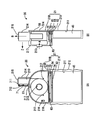
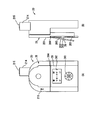
- FIG. 2 is a front view (A) and a side view (B) of the apparatus main body.
- the apparatus main body 20 has a casing 21 composed of a casing lower part 21A and a casing upper part 21B.
- the housing upper portion 21B is provided above the housing lower portion 21A, and has a shape protruding forward (in the direction of arrow Z shown in FIG. 2B) from the housing lower portion 21A, whereby the housing lower portion 21A.
- the thickness dimension in the front-rear direction is larger than that.
- the rear surface side of the housing 21 is formed on substantially the same surface by the housing lower portion 21A and the housing upper portion 21B.
- the lower housing portion 21A of the housing 21 is inserted into the breast pocket 2a (see FIG. 1), and the upper housing portion 21B has a deep chest on the lower surface of the upper housing portion 21B even when the chest pocket 2a is deep. It rides on the upper edge of the pocket 2a and protrudes over the breast pocket 2a.
- the battery housing chamber 211 for housing the battery 45 is provided in the housing lower part 21A. Since the battery 45 is a heavy built-in product, the battery 45 is configured to be housed in the housing lower portion 21A so that the apparatus main body 20 is stably inserted into the breast pocket.
- the housing lower portion 21 ⁇ / b> A has a corrugated shape on both side outer surfaces 212. This is to prevent the casing lower part 21A inserted into the breast pocket 2a from inadvertently coming out of the breast pocket 2a.
- a turbo fan 50 having an air dynamic pressure bearing as a fan is built in the housing upper part 21B.
- the turbo fan 50 plays a role of taking in air from the outside and sending it out toward the mask 40 via the hose 30 (see FIG. 1).
- an air intake port 213 having a slightly protruding shape is formed on the front surface of the housing upper part 21B.
- casing upper part 21B has the hose connection part 214 of the shape which protruded cylindrically upwards, and the air blower outlet 215 is formed in the upper end. Air flows in from the air inlet 213 along the arrow A and blows out from the air outlet 215 along the arrow B.
- the turbo fan 50 employs an air dynamic pressure bearing, so that it is significantly reduced in size and weight.
- the device main body 20 can be held in the breast pocket in a state where the weight balance with the battery 45 is good and the sense of stability is further improved.
- the hose connection part 214 has a role which connects the apparatus main body 20 and the hose 30 by the hose 30 (refer FIG. 1) being inserted there.
- An air flow path 219 through which air blown from the turbo fan 50 flows is formed inside the hose connection portion 214, and a flow rate sensor 711 that measures the flow rate and pressure of the air flowing through the air flow path 219, respectively.
- the flow sensor 711 and the pressure sensor 712 are connected to an MPU (Micro Processing Unit) 72 via a sensor connector 61.
- MPU Micro Processing Unit
- control board 73 and a controller reception board 74 on which the MPU 72 is mounted are further incorporated in the housing upper part 21B.
- the electric power from the battery 45 is supplied to the controller receiving board 74 via the battery connector 62, and is supplied to each unit that requires electric power via the controller receiving board 74.
- a communication connector 63 is connected to the controller reception board 74, and a signal from a controller described later is input to the controller reception board 74 via the communication connector 63.
- the controller receiving board 74 and the control board 73 are connected by a connector 64, and the control board 73 and the motor drive board 514 incorporated in the turbofan 50 are connected by a connector 65.
- a power switch 216 is provided on the front surface of the upper part 21B of the housing.
- an attachment mounting recess 217 which will be described later, is formed on the front surface of the housing upper part 21B.
- indentations 218 are formed at positions on the left and right sides of the upper part 21B of the casing and closer to the lower part 21A of the casing. This recess 218 becomes a finger hook when the apparatus main body 20 inserted in the breast pocket 2a (see FIG. 1) is pulled out from the breast pocket 2a.
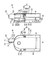
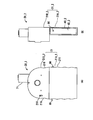
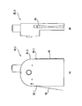
- FIG. 3 is a front view (A) and a side view showing a state in which the attachment of the first example is attached to the apparatus main body.
- the attachment 22 is attached to the main body housing 21 so as to face the front surface of the upper housing portion 21B, and extends downward with a space between the front surface of the lower housing portion 21A. It has a body 221.
- the attachment 22 is formed with a recess 22c into which the air intake 212 protruding from the front surface of the housing upper part 21B is fitted, and a projection 22d to be fitted into the attachment mounting recess 217 provided in the housing upper part 21B.
- the attachment 22 is pressed by aligning the positions of the irregularities, the irregularities fit tightly and the attachment 22 is fixed to the apparatus main body 20. Further, when the attachment 22 fixed to the housing main body 20 is pulled by placing a finger on a finger hook portion 22e provided in the lower portion of the attachment 22 and the fitting is uneven, the attachment 22 is separated from the apparatus main body 20.
- a filter 222 and a silencer 223 are built in the attachment housing 221 of the attachment 22 in the attachment housing 221 of the attachment 22.
- the filter 222 has a function of removing dust mixed in air taken in from the outside, and the silencer 223 reduces the inflow sound of air.
- the attachment 22 is positioned in front of the breast pocket 2a.
- FIG. 4 is a front view (A) and a side view (B) showing a state where the attachment of the second example, which is different from the attachment shown in FIG.
- the apparatus main body 20 is the same as that in FIG.
- the attachment 23 is obtained by adding a controller 24 to the attachment 22 shown in FIG.
- the attachment 23 has the same shape as the attachment 22 shown in FIG. 3 except that a controller 24 is added. Here, only this controller 24 will be described.
- the controller 24 has operation buttons 241 and a display screen 242.
- the attachment 23 is configured to communicate with the apparatus main body 20 via the communication connector 63 shown in FIGS.
- the operation button 241 has a recessed shape so that it can be easily operated even if it is a handcuff without the patient checking it.
- the patient sets the pressure range of the air sent out from the turbo fan 50, the on / off timing of the turbo fan 50, etc. designated by the doctor, separately from the fixed mode and the auto mode. .
- the fixed mode is a mode in which the pressure of the air sent from the turbo fan 50 is fixed to a specified pressure
- the auto mode is a state in which the patient's breathing is determined based on changes in the flow rate and pressure by the flow rate sensor 711 and the pressure sensor 712. In this mode, the pressure is detected and changed within a specified pressure range in accordance with the respiratory state of the patient.
- the display screen 242 displays the operation menu of the operation buttons 241 and the current flow rate and pressure of the apparatus main body 20.
- the display screen 242 is displayed in a display format that is reversed upside down.
- the display screen 242 is looked up from above, and the screen is displayed in the upside down display format. Is visible.
- the turbo fan 50 employed in the CPAP device of this embodiment is a fan provided with an air dynamic pressure bearing. With this, the CPAP apparatus of the present embodiment has succeeded in greatly reducing the size and weight of the apparatus main body 20.
- turbofan provided with an air dynamic pressure bearing employed in the CPAP device of this embodiment.
- the turbofan described here is the same as that disclosed in Patent Documents 2 and 3 described above in terms of operation principle.
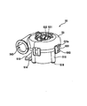
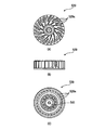
- FIG. 5 is an external perspective view of the turbo fan 50 employed in the CPAP device of the first embodiment
- FIG. 6 is a plan view of the turbo fan 50.
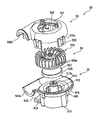
- FIGS. 7 and 8 are exploded perspective views of the turbo fan 50 as viewed obliquely from above and obliquely below, respectively.
- FIG. 9 is a view showing a blade 529 which is a part of the turbo fan 50.
- FIGS. 9A, 9B, and 9C are a plan view, a side view, and a bottom view, respectively.
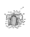
- FIG. 10 is a cross-sectional view of the turbo fan 50 in the direction indicated by the arrow AA in FIG.
- turbofan 50 will be described with reference to the cross-sectional view of FIG. 10 and referring to other drawings as necessary.
- the turbo fan 50 is roughly composed of a stator 51, a rotor 52, and an upper cover 53.
- the stator 51 is based on an annular shaft base 511, and a lower portion of the shaft 512 is fitted and fixed in a central hole 511a of the annular shaft base 511.
- An upper end portion 512a of the shaft 512 has a small diameter, and an annular thrust magnet (inner side) 513 is fixed so that the upper end portion 512a is fitted.
- a motor drive board 514 is placed on the shaft base 511.
- the motor drive board 514 is formed with a hole 514a through which the shaft 512 passes, and extends so as to surround the shaft 512.
- the motor drive board 514 extends so that a part of the motor drive board 514 protrudes to the outside, and a connector 515 for connection to an external circuit is disposed at the protruded part.
- annular coil base 516 surrounding the shaft 512 is placed a little apart from the shaft 512.
- the coil base 516 is provided with leg portions 516a which are inserted into holes 514b provided in the motor drive board 514 and supported by the shaft base 511 at a plurality of locations in the circumferential direction. That is, the coil base 516 is supported by the shaft base 511 by the leg portion 516 a and has a shape that makes a round around the upper surface of the motor drive board 514 with the shaft 512 as the center.
- a coil 517 formed in a cylindrical shape as a whole is placed on the coil base 516, and the lower end of the coil 517 is fixed to the coil base 516.
- the coil 517 is supplied with three-phase pulse power.
- a case 518 is screwed to the shaft base 511 with a screw 519.
- the rotor 52 is based on the hub 521.
- a hole 521a is formed in the upper portion of the hub 521, and an annular thrust magnet (outside) 522 is fixed to the edge of the hole 521a.
- the inner peripheral surface of the thrust magnet (outer side) 522 faces the outer peripheral surface of the thrust magnet (inner side) 513 with a very narrow gap therebetween, and the sintered body 541 and the shaft upper end portion are attracted by mutual magnetic forces. Contact in the thrust direction of 512a is avoided.
- a cylindrical sleeve 524 is fixed to the hub 521.
- the inner peripheral surface of the sleeve 524 faces the outer peripheral surface of the shaft 512, and an extremely narrow gap of ⁇ m unit is formed between the sleeve 524 and the shaft 512.
- a magnet 525 is fixed to the outer peripheral surface of the sleeve 524, and a reinforcing ring 526 is attached to the outer peripheral surface of the magnet 525. Since the rotor 52 of the turbofan 50 rotates at a high speed, the magnet 525 may be broken by a centrifugal force, and the reinforcing ring 526 is for preventing the crack.
- the outer peripheral surface of the reinforcing ring 526 faces the inner peripheral surface of the coil 517 across a narrow space. Further, a back yoke 527 is disposed on the outer peripheral surface side of the coil 517 with a space between the coil 517 and the coil 517.
- the back yoke 527 has a role of forming a magnetic circuit together with the magnet 525 and enhancing the interaction with the coil 517.
- a balance ring 528 is fixed to the lower portion of the back yoke 527.
- the balance ring 528 is a member for adjusting the balance when the rotor 52 rotates.
- a blade 529 (see also FIG. 8) is fixed to the upper portion of the hub 521.
- the blade 529 is a component that sends out air by the rotation of the rotor 52.
- a sintered body 541 is fixed to the lower center of the blade 529.
- the sintered body 541 is for giving a damper effect to the gap between the stator 51 and the rotor 52.
- the rotor effect is obtained by the damper effect. Since the abrupt movement of 52 can be suppressed, the rotor 52 can rotate at high speed without contact with the stator 51.
- the sintered body 541 is in a position facing the upper end portion 512 a of the shaft 512 of the stator 51.
- a bypass hole 529a is formed in the blade 529. This bypass hole 529a reduces the pressure difference between the inside and outside of the blade 529 when air resistance on the air delivery side increases or the air intake side is blocked and air flows through the bypass hole 529a. It plays a role of suppressing movement of the blade 529 and the like.
- the upper cover 53 is provided with an air intake port 531 at the upper portion thereof, and a cylindrical air discharge port 542 is formed on the side portion in cooperation with the semi-cylindrical portion 542 a on the stator 51 side.
- a semi-cylindrical portion 542b is formed.
- the upper cover 53 has a locking hole 533a formed in a locking portion 533 formed so as to protrude downward on the side surface thereof and a locking projection 543 formed on the side surface of the case 518 of the stator 51. As a result, the stator 51 is fixed to the case 518 with a little space between the blade 529 and the case 518.
- a stopper 532 exposed downward is provided at the center of the upper cover 53.
- the stopper 532 is caused by a pressure difference between the inside and outside of the blade 529.
- the upper center of the blade 529 is abutted against the stopper 532 to prevent the blade 529 from being damaged.
- This turbofan 50 has the above-described structure, and three-phase pulse power is applied to the coil 517, and the rotor 52 rotates at a rotation speed corresponding to the repetition frequency of the three-phase pulse.
- the turbo fan 50 has a structure in which the stator 51 and the rotor 52 are not in contact with each other and an air dynamic pressure bearing is provided between them. As a fan that can produce the necessary air volume.
- turbo fan 50 provided with the air dynamic pressure bearing
- the fan that can be employed in the CPAP device of the present invention is not necessarily provided with the air dynamic pressure bearing.
- it may be provided with a fluid dynamic pressure bearing such as oil filled between the rotor and the rotor, and further provided with a general bearing such as a ball bearing instead of a fluid dynamic pressure bearing. It may be a thing.
- FIG. 11 is a control block diagram of the CPAP device according to the first embodiment of the present invention.
- the apparatus main body 20, the hose 30, and the mask 40 are components that are absolutely necessary when the CPAP apparatus is used.
- the attachment 22 (23) (see FIGS. 3 and 4) is a component that can be attached to the apparatus main body 20.
- the controller 24 is a component that is coupled to the apparatus main body 20 when the attachment 23 of the type shown in FIG. 4 is attached to the apparatus main body 20.
- the memory 28 is an element required at the time of initial setting.
- the attachment 22 of the type without the controller shown in FIG. 3 is used, or when the apparatus main body 20 shown in FIG. 2 is used without attaching the attachment, the information read from the memory 28 becomes valid. .
- Setting information such as the on / off timing of is recorded.
- the setting information recorded in the memory 28 is information set under the guidance of a doctor or the like.
- the memory 28 is connected to the communication connector 63, and the setting information recorded in the memory 28 is installed in the apparatus main body 20.
- the installed setting information is transmitted to the MPU 72 mounted on the control board 73 via the controller reception board 74 and stored in the MPU 72.
- the controller 45 receives power from the battery 45.
- a power switch 216 (see also FIG. 2) for turning on / off a transmission path to the substrate 74 is turned on, the apparatus main body 20 operates according to setting information stored in the MPU 72.
- the controller 24 is connected to the controller receiving board 74 via the communication connector 63.
- the apparatus main body 20 operates based on the operation information input by the operation of the operation button 24 instead of the information stored in the MPU 72.
- the setting information set by the operation of the controller 24 is input to the controller reception board 74 via the communication connector 63.
- the controller reception board 74 includes a control unit 741 and an instruction signal generation unit 742.
- the control unit 741 receives setting information from the controller 74 and sends it to the setting signal generation unit 742, and also plays a role of controlling the display screen 242.
- a setting signal representing setting information from the controller 24 is generated.
- the generated setting signal is input to the MPU 72 mounted on the control board 73 via the connector 64.
- the air flow rate and air pressure measured by the flow sensor 711 and the pressure sensor 712 are also input to the MPU 72 on the control board 73 via the sensor connector 61.
- the rotational speed of the turbo fan 50 is calculated based on the information.
- the calculation result in the MPU 72 is transmitted to the motor drive circuit 771 on the motor drive board 514 via the connector 65, and the motor drive circuit 771 drives the turbo fan 50 based on the calculation result.
- FIG. 12 is a front view (A) and a side view (B) in a state in which the attachment of the third example is attached to the apparatus main body.
- the apparatus main body 20 is the same as that shown in FIG. 1 and FIG.
- the attachment 25 of the third example is the same as the attachment 23 of the second example shown in FIG. 4 except that the controller 26 is different, and the attachment 25 will be described only by the controller 26.
- the controller 26 has an operation button 261 and a display screen 262.
- the operation button 261 itself is the same as the operation button 241 of the controller 24 provided in the attachment 23 shown in FIG. 4, and the display screen 262 itself is the display screen of the controller 24 provided in the attachment 23 shown in FIG. The same as 242.
- the controller 26 provided in the attachment 25 shown in FIG. 5 has an operation button 261 and a display screen 262 mounted on a support plate 263, and the upper edge of the support plate 263 is attached to the attachment housing 251 via a hinge structure 264. Is supported by the front of the. As indicated by a two-dot chain line in FIG. 12, the controller 26 can be lifted so that the lower portion of the support plate 263 is away from the attachment housing 251. For the patient, lifting the controller 26 makes the display screen 262 visible and the operation buttons 261 easier to operate.
- FIG. 13 is a front view (A) and a side view (B) of the apparatus main body of the second embodiment. In FIG. 13, only necessary portions are shown in perspective, and other portions are shown only in outline.
- the apparatus main body 20_2 has a main body casing 21_2 including a casing lower portion 21A_2 and a casing upper portion 21B_2.
- the housing lower portion 21A_2 is detachable from the housing upper portion 21B_2.
- a secondary battery 45_2 is accommodated in the housing lower part 21A_2, and a charge board 46_2 that generates power by electromagnetic induction from the outside and charges the secondary battery 45_2 at a position adjacent to the secondary battery 45_2. Built in.
- attachments as shown in FIGS. 3 and 4 are often attached to the housing upper portion 21B_2.
- the housing Even if the attachment is attached to the upper portion 21_B, the housing lower portion 21A_2 can be removed and the built-in secondary battery 45_2 can be charged in a non-contact manner.
- FIG. 14 is a diagram showing an example of the attachment / detachment mechanism.
- FIG. 14A shows the mounting structure on the housing upper part 21B_1 side.
- a mounting piece 81 is shown which extends downward and has a groove 82 extending vertically in the center.
- the mounting piece 81 has two projecting pieces 83 projecting in a direction of narrowing the width of the groove 82 at a position slightly lower than the upper end of the groove 82 extending vertically.
- FIG. 14B shows the mounting structure on the housing lower part 21A_2 side. It has a cantilever-shaped elastic plate 84 whose upper end is a free end, and a lock piece 85 and a push button 86 are connected to the upper end portion of the elastic plate 84 by a small-diameter connecting portion 87. A lock portion is formed.
- the lock piece 85 is a space above the protruding piece 83 of the groove 82.
- the lock hole 82a is in a state where it is prevented from coming off.
- the push button 86 is in a position protruding from the side surface of the housing lower part 21 ⁇ / b> A_ ⁇ b> 2.
- the elastic plate 84 bends in the direction of arrow A and the small-diameter connecting portion 87 is positioned on the protruding piece 83. It becomes a state.
- the apparatus main body 20_2 of the second embodiment shown in FIG. 13 has mounting structures shown in FIG. 14 on both the left and right sides thereof, whereby the case upper part 21B_2 is detachable from the case lower part 21A_2.
- the housing lower part 21 ⁇ / b> A_ ⁇ b> 2 is configured as a battery pack, and the battery pack is removed so that it can be contactlessly charged. For example, by charging the battery when waking up in the morning, It is easy to achieve a fully charged state.
- FIG. 15 is a front view (A) and a side view (B) of the apparatus main body of the third embodiment.
- the apparatus main body 20_3 shown in FIG. 15 has a low-repulsive sponge 91 attached to both side surfaces of the housing lower part 21A_3.
- the sponge 91 tends to spread in the chest pocket when the lower housing portion 21A_3 is inserted into the breast pocket 2a (see FIG. 1), increases the frictional force with the inner surface of the chest pocket, and is difficult to come out of the breast pocket. Is to do.
- FIG. 16 is a front view (A) and a side view (B) of the apparatus main body of the fourth embodiment.
- the spring pieces 92 are provided on both sides of the main body casing 21_4 of the apparatus main body 20_4. Correspondingly, grooves 211_4 into which the spring pieces 92 enter are formed on both side surfaces of the main body casing 21_4.
- the spring piece 92 has a first state in which the upper and lower ends are fixed and the center shown on the left side of FIG. 16A swells, and a second state in which the center shown on the right side of FIG. It has two states.
- the left and right spring pieces 92 are inserted into the chest pocket in the second state in which the center is depressed, and after insertion, the left and right spring pieces 92 are inserted into the chest pocket. From the top, the central portion of the spring piece 92 is pulled to the first state where the center is swollen. This prevents the apparatus main body 20_4 inserted into the breast pocket from being accidentally pulled out of the breast pocket.
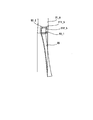
- FIG. 17 is a front view (A) and a side view (B) of the apparatus main body of the fifth embodiment.
- the apparatus body 20_5 shown in FIG. 17 is provided with retaining pieces 93 at both ends thereof.
- the retaining piece 93 has a shape bent outward at a position slightly lowered from the upper end, and the bent portion 93_1 is hinged to the main body casing 21_5.
- the retaining piece 93 has a first state in which the lower end is opened outward as shown on the left side of FIG. 17A and a lower end on the side surface of the main body casing 21_5 as shown on the right side of FIG. And a second state closed so as to follow.
- FIG. 18 is a view showing a lock structure for keeping the retaining piece 93 shown in FIG. 17 in the first state.
- a groove 211_5 into which a portion 93_2 of the retaining piece 93 above the hinge-connected portion 93_1 enters is formed in the main body casing 21_5.
- the groove 211_5 includes the retaining piece 93 that has entered the groove 211_5.
- both the left and right retaining pieces 93 are in the second state closed along the side surface of the main body casing 21_5, and are inserted into the breast pocket.
- the upper part 93_2 of 93 is pushed into the groove 211_5 to widen the lower part. This prevents the apparatus main body 20_5 from being accidentally pulled out of the breast pocket.
- FIG. 19 is a front view (A) and a side view (B) of the apparatus main body of the sixth embodiment.
- This apparatus main body 20_6 is provided with springy protruding pieces 94 having open ends at the left and right sides of the main body casing 21_6.
- the protruding piece 94 is in an open state as shown in FIG. 19A.
- the protruding piece 94 bends along the side surface of the main body housing 21_5, and returns to the open state when the hand is released.
- the protruding support piece 94 When this apparatus main body 20_6 is inserted into the breast pocket, the protruding support piece 94 is inserted while being bent along the side surface of the main body casing 21_5, and is opened in the breast pocket. For this reason, when the apparatus main body 20_5 is about to come out of the breast pocket, the upper end of the projecting support piece 94 projects and supports the inside of the breast pocket to prevent it from coming off. When this device main body 20_5 is pulled out from the breast pocket, it can be easily pulled out as it is by pressing the protruding piece 94 from the outside of the breast pocket and bending it along the side surface of the main body casing 21_5.
- FIG. 20 is a front view (A) and a side view (B) of the apparatus main body of the seventh embodiment.
- a magnetic plate 96 is attached to the back surface of the main body casing 21_7 of the apparatus main body 20_7 of the seventh embodiment.
- a magnet plate 97 is attached to the inner side of the clothing 2 at a position facing the breast pocket 2a.
- the magnetic plate 96 attached to the back surface of the main body casing 21 is attracted to the magnet plate 97, thereby stabilizing the apparatus main body 20_7 in the breast pocket 2a. Retained.
- the apparatus main body 20_7 of the seventh embodiment can also fix the apparatus main body 20_7 to the surface of the shirt regardless of the breast pocket.
Landscapes
- Engineering & Computer Science (AREA)
- Health & Medical Sciences (AREA)
- General Engineering & Computer Science (AREA)
- Mechanical Engineering (AREA)
- Life Sciences & Earth Sciences (AREA)
- Biomedical Technology (AREA)
- Heart & Thoracic Surgery (AREA)
- Hematology (AREA)
- Anesthesiology (AREA)
- Animal Behavior & Ethology (AREA)
- General Health & Medical Sciences (AREA)
- Public Health (AREA)
- Veterinary Medicine (AREA)
- Pulmonology (AREA)
- Emergency Medicine (AREA)
- Structures Of Non-Positive Displacement Pumps (AREA)
Abstract
La présente invention concerne un dispositif à pression positive continue des voies respiratoires utilisé pour le traitement du syndrome d'apnée du sommeil et qui permet une manipulation facile tout en mitigeant le fardeau imposé aux patients. La présente invention comprend un corps principal de dispositif doté de : un boîtier de corps principal, ayant une partie inférieure de boîtier et une partie supérieure de boîtier qui est prévue au-dessus de la partie inférieure de boîtier, a une épaisseur plus importante dans la direction avant-arrière que la partie inférieure de boîtier étant donné qu'il a une forme qui dépasse davantage sur l'avant que la partie inférieure de boîtier, et a une ouverture d'entrée d'air formée au niveau de l'avant et une ouverture d'évacuation d'air formée dans la partie supérieure; un compartiment pour batterie fourni dans la partie inférieure de boîtier; et un ventilateur qui est incorporé dans la partie supérieure de boîtier et qui aspire l'air de l'ouverture d'entrée d'air et l'expulse par l'ouverture d'évacuation d'air.
Applications Claiming Priority (2)
| Application Number | Priority Date | Filing Date | Title |
|---|---|---|---|
| JP2013-056548 | 2013-03-19 | ||
| JP2013056548A JP6143508B2 (ja) | 2013-03-19 | 2013-03-19 | Cpap装置 |
Publications (1)
| Publication Number | Publication Date |
|---|---|
| WO2014147675A1 true WO2014147675A1 (fr) | 2014-09-25 |
Family
ID=51579417
Family Applications (1)
| Application Number | Title | Priority Date | Filing Date |
|---|---|---|---|
| PCT/JP2013/005827 Ceased WO2014147675A1 (fr) | 2013-03-19 | 2013-09-30 | Dispositif cpap |
Country Status (2)
| Country | Link |
|---|---|
| JP (1) | JP6143508B2 (fr) |
| WO (1) | WO2014147675A1 (fr) |
Cited By (3)
| Publication number | Priority date | Publication date | Assignee | Title |
|---|---|---|---|---|
| CN105288808A (zh) * | 2015-11-27 | 2016-02-03 | 吉林省沃鸿医疗器械制造有限公司 | 呼吸机 |
| WO2018190159A1 (fr) * | 2017-04-10 | 2018-10-18 | 株式会社村田製作所 | Dispositif de type soufflante et dispositif de régulation de fluide |
| US20220152335A1 (en) * | 2019-08-08 | 2022-05-19 | Murata Manufacturing Co., Ltd. | Cpap device |
Families Citing this family (1)
| Publication number | Priority date | Publication date | Assignee | Title |
|---|---|---|---|---|
| JP6891038B2 (ja) | 2017-05-15 | 2021-06-18 | オムロン株式会社 | ウエアラブル装置およびプログラム |
Citations (2)
| Publication number | Priority date | Publication date | Assignee | Title |
|---|---|---|---|---|
| JP2012522609A (ja) * | 2009-04-02 | 2012-09-27 | ブリーズ・テクノロジーズ・インコーポレーテッド | 外側管内の気体運搬ノズルでの非侵襲性開放換気のための方法、システムおよびデバイス |
| JP2013501541A (ja) * | 2009-08-11 | 2013-01-17 | レスメド・モーター・テクノロジーズ・インコーポレーテッド | 単一ステージの、軸対称送風機および携帯可能な人工呼吸器 |
Family Cites Families (2)
| Publication number | Priority date | Publication date | Assignee | Title |
|---|---|---|---|---|
| JP2009125303A (ja) * | 2007-11-22 | 2009-06-11 | Terumo Corp | 酸素濃縮装置 |
| US20110240011A1 (en) * | 2010-03-31 | 2011-10-06 | Elivn L. Haworth | Treating apparatus |
-
2013
- 2013-03-19 JP JP2013056548A patent/JP6143508B2/ja not_active Expired - Fee Related
- 2013-09-30 WO PCT/JP2013/005827 patent/WO2014147675A1/fr not_active Ceased
Patent Citations (2)
| Publication number | Priority date | Publication date | Assignee | Title |
|---|---|---|---|---|
| JP2012522609A (ja) * | 2009-04-02 | 2012-09-27 | ブリーズ・テクノロジーズ・インコーポレーテッド | 外側管内の気体運搬ノズルでの非侵襲性開放換気のための方法、システムおよびデバイス |
| JP2013501541A (ja) * | 2009-08-11 | 2013-01-17 | レスメド・モーター・テクノロジーズ・インコーポレーテッド | 単一ステージの、軸対称送風機および携帯可能な人工呼吸器 |
Cited By (6)
| Publication number | Priority date | Publication date | Assignee | Title |
|---|---|---|---|---|
| CN105288808A (zh) * | 2015-11-27 | 2016-02-03 | 吉林省沃鸿医疗器械制造有限公司 | 呼吸机 |
| WO2018190159A1 (fr) * | 2017-04-10 | 2018-10-18 | 株式会社村田製作所 | Dispositif de type soufflante et dispositif de régulation de fluide |
| JPWO2018190159A1 (ja) * | 2017-04-10 | 2019-11-07 | 株式会社村田製作所 | 送風装置及び流体制御装置 |
| US11904092B2 (en) | 2017-04-10 | 2024-02-20 | Murata Manufacturing Co., Ltd. | Air-blowing device and fluid control apparatus |
| US20220152335A1 (en) * | 2019-08-08 | 2022-05-19 | Murata Manufacturing Co., Ltd. | Cpap device |
| US12364836B2 (en) * | 2019-08-08 | 2025-07-22 | Murata Manufacturing Co., Ltd. | CPAP device with sealing member between two detachable units |
Also Published As
| Publication number | Publication date |
|---|---|
| JP6143508B2 (ja) | 2017-06-07 |
| JP2014180411A (ja) | 2014-09-29 |
Similar Documents
| Publication | Publication Date | Title |
|---|---|---|
| US12465704B2 (en) | Manifold for respiratory therapy apparatus | |
| CN102695536B (zh) | 单级轴对称鼓风机和便携式通风机 | |
| JP6143508B2 (ja) | Cpap装置 | |
| JP7514955B2 (ja) | ウェアラブル空気清浄機 | |
| JP2021041258A (ja) | Cpap装置 | |
| JP5358773B1 (ja) | 呼吸補助装置 | |
| CN106620978A (zh) | 呼吸辅助设备 | |
| JP2017537708A (ja) | 液体チャンバの切り離しシステム及び方法 | |
| JP6620016B2 (ja) | ポータブル手持ち用圧力支援システム及び方法 | |
| CN115025412A (zh) | 呼吸器 | |
| CN116262162A (zh) | 用于优化呼吸保护设备中的气流的装置和方法 | |
| US20140014110A1 (en) | Remotely controlled positive airway-pressure apparatus and method | |
| US20160317780A1 (en) | Reversible component for multiple respiratory support modes | |
| CN111955826B (zh) | 一种双层正压穿戴式防护装置 | |
| WO2022180272A1 (fr) | Dispositif d'aide à la respiration pour masque de protection respiratoire | |
| EP4122547B1 (fr) | Appareil de masquage et procédé de commande correspondant | |
| TW202133746A (zh) | 氣溶膠產生裝置 | |
| US10483778B2 (en) | Battery system with low power mode | |
| CN218790544U (zh) | 一种调气机构和具有其的电子雾化装置 | |
| JP6120352B2 (ja) | Cpap装置 | |
| CN111588083A (zh) | 电子烟 | |
| US20230293915A1 (en) | Electric breathing apparatus and air filter device therefor | |
| JP2021010467A (ja) | 呼吸器用送風装置 | |
| CN221104794U (zh) | 一种解压电子烟 | |
| CN208809011U (zh) | 便携式慢阻肺辅助治疗装置 |
Legal Events
| Date | Code | Title | Description |
|---|---|---|---|
| 121 | Ep: the epo has been informed by wipo that ep was designated in this application |
Ref document number: 13878680 Country of ref document: EP Kind code of ref document: A1 |
|
| NENP | Non-entry into the national phase |
Ref country code: DE |
|
| 122 | Ep: pct application non-entry in european phase |
Ref document number: 13878680 Country of ref document: EP Kind code of ref document: A1 |