WO2014147774A1 - 通信方法、通信装置、および、通信プログラム - Google Patents
通信方法、通信装置、および、通信プログラム Download PDFInfo
- Publication number
- WO2014147774A1 WO2014147774A1 PCT/JP2013/057920 JP2013057920W WO2014147774A1 WO 2014147774 A1 WO2014147774 A1 WO 2014147774A1 JP 2013057920 W JP2013057920 W JP 2013057920W WO 2014147774 A1 WO2014147774 A1 WO 2014147774A1
- Authority
- WO
- WIPO (PCT)
- Prior art keywords
- packet
- communication device
- communication
- transfer
- value
- Prior art date
- Legal status (The legal status is an assumption and is not a legal conclusion. Google has not performed a legal analysis and makes no representation as to the accuracy of the status listed.)
- Ceased
Links
Images





Classifications
-
- H—ELECTRICITY
- H04—ELECTRIC COMMUNICATION TECHNIQUE
- H04L—TRANSMISSION OF DIGITAL INFORMATION, e.g. TELEGRAPHIC COMMUNICATION
- H04L1/00—Arrangements for detecting or preventing errors in the information received
- H04L1/12—Arrangements for detecting or preventing errors in the information received by using return channel
- H04L1/16—Arrangements for detecting or preventing errors in the information received by using return channel in which the return channel carries supervisory signals, e.g. repetition request signals
- H04L1/18—Automatic repetition systems, e.g. Van Duuren systems
- H04L1/1812—Hybrid protocols; Hybrid automatic repeat request [HARQ]
- H04L1/1819—Hybrid protocols; Hybrid automatic repeat request [HARQ] with retransmission of additional or different redundancy
-
- H—ELECTRICITY
- H04—ELECTRIC COMMUNICATION TECHNIQUE
- H04L—TRANSMISSION OF DIGITAL INFORMATION, e.g. TELEGRAPHIC COMMUNICATION
- H04L1/00—Arrangements for detecting or preventing errors in the information received
- H04L1/0001—Systems modifying transmission characteristics according to link quality, e.g. power backoff
- H04L1/0009—Systems modifying transmission characteristics according to link quality, e.g. power backoff by adapting the channel coding
-
- H—ELECTRICITY
- H04—ELECTRIC COMMUNICATION TECHNIQUE
- H04L—TRANSMISSION OF DIGITAL INFORMATION, e.g. TELEGRAPHIC COMMUNICATION
- H04L1/00—Arrangements for detecting or preventing errors in the information received
- H04L1/12—Arrangements for detecting or preventing errors in the information received by using return channel
- H04L1/16—Arrangements for detecting or preventing errors in the information received by using return channel in which the return channel carries supervisory signals, e.g. repetition request signals
- H04L1/18—Automatic repetition systems, e.g. Van Duuren systems
- H04L1/1867—Arrangements specially adapted for the transmitter end
- H04L1/1887—Scheduling and prioritising arrangements
-
- H—ELECTRICITY
- H04—ELECTRIC COMMUNICATION TECHNIQUE
- H04L—TRANSMISSION OF DIGITAL INFORMATION, e.g. TELEGRAPHIC COMMUNICATION
- H04L43/00—Arrangements for monitoring or testing data switching networks
- H04L43/06—Generation of reports
- H04L43/062—Generation of reports related to network traffic
-
- H—ELECTRICITY
- H04—ELECTRIC COMMUNICATION TECHNIQUE
- H04L—TRANSMISSION OF DIGITAL INFORMATION, e.g. TELEGRAPHIC COMMUNICATION
- H04L43/00—Arrangements for monitoring or testing data switching networks
- H04L43/08—Monitoring or testing based on specific metrics, e.g. QoS, energy consumption or environmental parameters
- H04L43/0852—Delays
- H04L43/0864—Round trip delays
-
- H—ELECTRICITY
- H04—ELECTRIC COMMUNICATION TECHNIQUE
- H04L—TRANSMISSION OF DIGITAL INFORMATION, e.g. TELEGRAPHIC COMMUNICATION
- H04L43/00—Arrangements for monitoring or testing data switching networks
- H04L43/16—Threshold monitoring
-
- H—ELECTRICITY
- H04—ELECTRIC COMMUNICATION TECHNIQUE
- H04L—TRANSMISSION OF DIGITAL INFORMATION, e.g. TELEGRAPHIC COMMUNICATION
- H04L45/00—Routing or path finding of packets in data switching networks
- H04L45/28—Routing or path finding of packets in data switching networks using route fault recovery
-
- H—ELECTRICITY
- H04—ELECTRIC COMMUNICATION TECHNIQUE
- H04L—TRANSMISSION OF DIGITAL INFORMATION, e.g. TELEGRAPHIC COMMUNICATION
- H04L45/00—Routing or path finding of packets in data switching networks
- H04L45/70—Routing based on monitoring results
-
- H—ELECTRICITY
- H04—ELECTRIC COMMUNICATION TECHNIQUE
- H04L—TRANSMISSION OF DIGITAL INFORMATION, e.g. TELEGRAPHIC COMMUNICATION
- H04L45/00—Routing or path finding of packets in data switching networks
- H04L45/74—Address processing for routing
-
- H—ELECTRICITY
- H04—ELECTRIC COMMUNICATION TECHNIQUE
- H04L—TRANSMISSION OF DIGITAL INFORMATION, e.g. TELEGRAPHIC COMMUNICATION
- H04L43/00—Arrangements for monitoring or testing data switching networks
- H04L43/08—Monitoring or testing based on specific metrics, e.g. QoS, energy consumption or environmental parameters
- H04L43/0823—Errors, e.g. transmission errors
- H04L43/0829—Packet loss
- H04L43/0841—Round trip packet loss
Definitions
- the present invention relates to communication performed between a plurality of communication devices.
- the communication device on the transmission side uses the confirmation response packet from the communication device on the reception side, and then Determines the size of data to be transmitted and whether to perform retransmission.
- the round trip delay time (Round Trip Time, RTT) of the path between the transmission side communication device and the reception side communication device becomes longer as the distance between the transmission side communication device and the reception side communication device becomes longer.
- the state parameter is quality information required according to an application in which data is used, such as a bandwidth and an allowable delay time.
- the connection parameter is information regarding the communication connection.
- the method of retransmitting a packet lost during communication there is a problem that if the distance between the communication device on the transmission side and the communication device on the reception side is increased, the communication speed is lowered due to an increase in the round-trip delay time.
- the method of transmitting redundant packets used for error correction can prevent a decrease in communication speed due to retransmission processing, but there is a problem that throughput is reduced by transmitting redundant packets.
- a communication device that employs a communication method that employs a method with low jitter among the available communication methods can reduce fluctuations in the time taken to transmit each packet, but cannot increase the communication speed.
- a communication method is determined using quality information required by an application. For this reason, there is a problem that a communication method cannot be appropriately selected unless quality information is known. Therefore, the method of determining the communication method using the quality information cannot be applied to a communication device that transfers data used in an unspecified application.
- An object of one aspect of the present invention is to provide a method for suppressing delay while preventing a decrease in throughput.
- the network in which the communication method according to the embodiment is used includes a first communication device, a second communication device, and a third communication device.
- the second communication device specifies a transfer packet, which is a packet to be transferred to the third communication device, from the packet received from the first communication device.
- the second communication device measures an interval at which the transfer packet is received from the first communication device.
- the second communication device transfers the transfer packet to the third communication device.
- the second communication device receives notification information for notifying the reception status of the transfer packet from the third communication device.
- the second communication device uses the notification information to select a target packet that is a packet that has not been notified of successful reception from the third communication device, out of the packets transferred to the third communication device. To do.
- the second communication device retransmits the target packet to the third communication device in a form capable of error correction when an interval for receiving the transfer packet from the first communication device exceeds a threshold. .
- ⁇ Delay can be suppressed while preventing a decrease in throughput.
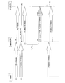
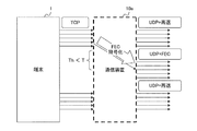
- FIG. 1 shows an example of a communication method according to the embodiment.
- the terminal transmits a packet toward the communication apparatus B.
- the communication device A transfers the packet received from the terminal to the communication device B.
- Thick arrows in FIG. 1 indicate a plurality of packets.
- a combination of a letter “P” and a number indicates a packet transmitted from the terminal, and a number following P indicates a sequence number of the packet.
- a white arrow indicates communication in a communication method in which a packet that has failed to be received by the receiving side is retransmitted from the transmitting side.
- a communication method in which a packet on which the reception side has failed to be received is retransmitted from the transmission side may be referred to as a “retransmission base” communication method.
- a arrow including stippling indicates communication performed by a method of transmitting a redundant packet used for error correction.
- a method of transmitting redundant packets used for error correction may be described as an “error correction base” communication method.
- the terminal transmits packets P0 to P9999 to the communication apparatus B by a retransmission-based communication method.
- the communication apparatus A has received all the packets transmitted from the terminal.
- the communication device A transfers the packet received from the terminal to the communication device B by a retransmission-based method. At this time, it is assumed that the communication device B fails to receive the packet of P100 among the packets transmitted from the communication device A.
- the terminal transmits packets P10000 to P19999 to the communication apparatus B by a retransmission-based communication method.
- the communication device B transmits a control response packet (Ack) for notifying the communication device A of the reception status of the packet at a predetermined time interval.
- the reception status at the time when the control response packet is generated is recorded in the control response packet.
- the communication apparatus B transmits a control response packet notifying that the reception of P100 has failed to the communication apparatus A.
- the communication apparatus A recognizes that transmission of P0 to P99 and P101 to P9999 to the communication apparatus B was successful and transmission of P100 to the communication apparatus B failed.
- the communication device A transmits the packets P10000 to P19999 received from the terminal in a retransmission-based manner between the time when the control response packet is transmitted from the communication device B and the time when the processing of the control response packet ends. Forward to B.
- the communication apparatus A determines that the period during which transfer processing of a new packet to the communication apparatus B is interrupted exceeds the threshold Th.
- the threshold value Th is set to a time shorter than the round-trip delay time (RTT).
- the communication apparatus A When the period during which the transfer process of a new packet is interrupted exceeds the threshold Th, the communication apparatus A retransmits a packet whose transfer has not been confirmed to the communication apparatus B using an error correction based transmission method. To do. At this time, since the communication device A has not received a new control response packet from the communication device B, the communication device A does not know whether transmission has been successful for P10000 to P19999. Further, the communication device A recognizes that the transfer of the packet of P100 has failed in the procedure (4). Therefore, the communication apparatus A retransmits the packets of P100 and P10000 to P19999 to the communication apparatus B on an error correction basis.
- the communication device B can receive P100 and P10000 to P19999 by the packet retransmitted from the communication device A.
- the communication device B can restore the packet that has failed to be received using a redundant packet or the like.
- the terminal newly transmits packets P20000 to P29999 to the communication device A. Then, the communication apparatus A transfers P20000 to P29999 to the communication apparatus B by a retransmission-based communication method.
- the communication device A determines that the available bandwidth for packet transfer has increased. Therefore, in the interval of transferring a new packet, a packet whose transfer has not been successfully confirmed is transferred again by an error correction-based communication method. For this reason, a retransmission process is performed for a packet waiting for a control response packet without waiting for the arrival of the control response packet. Therefore, a packet that is waiting for a control response packet and has failed to be transmitted for the first time is retransmitted before the round-trip delay time (RTT) elapses. Therefore, when the communication method according to the embodiment is used, the delay can be suppressed even if the RTT becomes long.
- RTT round-trip delay time
- the round trip delay time between the communication device A and the communication device B is from the transmission time of a packet (measurement packet) used for measuring the time required for communication to the reception time of the response packet of the measurement packet.
- Time For example, from the time when the communication device A transmits the first measurement packet to the communication device B to the time when the communication device A receives the second measurement packet transmitted from the communication device B as a response to the first measurement packet. Is the RTT between the communication device A and the communication device B.
- the communication device transmits a redundant packet in retransmission performed in the middle of transferring a new packet, but does not transmit a redundant packet while communicating on a retransmission basis. For this reason, in the communication method according to the embodiment, it is possible to suppress a decrease in throughput due to the transmission of redundant packets.
- a case where a packet addressed to the communication device B is transmitted from the terminal is described as an example.
- the packet from the terminal is transmitted to the other device via the communication device B. It may be transferred to the device.
- FIG. 2 shows an example of a network in which the communication apparatus 10 according to the embodiment is used.
- FIG. 2 shows an example of a network when the terminal 1 and the server 4 in the data center 3 communicate with each other across the Wide Area Network (WAN) 2.
- WAN Wide Area Network
- the data center 3 includes a communication device 10b and a server 4.
- the terminal 1 is assumed to access the WAN 2 via the communication device 10a.
- the communication device 10a and the communication device 10b can operate as a WAN acceleration device.
- the number of terminals 1 and the number of servers 4 included in the data center 3 are arbitrary.
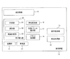
- FIG. 3 shows an example of the configuration of the communication device 10.
- the communication device 10 includes a transmission unit 11, a reception unit 12, a transmission / reception unit 13, a transfer processing unit 14, a retransmission processing unit 15, a packet processing unit 16, a received packet management unit 17, a bandwidth calculation unit 18, and a switching unit 20.
- the switching unit 20 includes a measurement unit 21, a selection unit 22, and a threshold value calculation unit 23.
- the transmission unit 11 is used when the communication device 10 transmits a packet to a device included in the WAN 2 or another communication device 10.
- the transmission unit 11 transmits a packet input from the transfer processing unit 14, the retransmission processing unit 15, the received packet management unit 17, and the like toward the destination.
- the receiving unit 12 receives a packet from a device included in the WAN 2 or another communication device 10.
- the receiving unit 12 outputs the received packet to the packet processing unit 16.
- the transmission / reception unit 13 is used when the communication device 10 transmits / receives a packet to / from the terminal 1 or the server 4.
- the transmission / reception unit 13 outputs the packet received from the terminal 1 to the selection unit 22.
- the transfer processing unit 14 converts the packet input from the selection unit 22 into a packet for transmission to the WAN 2 using a retransmission-based communication method, and outputs the packet to the transmission unit 11.
- the retransmission processing unit 15 converts the packet input from the selection unit 22 into a packet for transmission to the WAN 2 using an error correction based communication method, and outputs the packet to the transmission unit 11.
- the packet format will be described later.
- the packet processing unit 16, the received packet management unit 17, and the bandwidth calculation unit 18 perform processing when the communication device 10 receives a packet from another communication device 10 connected via the WAN 2.
- the packet processing unit 16 converts a packet received from another communication device 10 into a format that can be transmitted to the terminal 1 or the server 4.
- the packet processing unit 16 outputs the processed packet to the transmission / reception unit 13. Then, the transmission / reception unit 13 transmits a packet addressed to the terminal 1 or the server 4 to the terminal 1 or the server 4.
- the received packet management unit 17 monitors the reception status at the packet processing unit 16. For example, the received packet management unit 17 specifies the maximum value of the sequence ID of the currently received packet and the sequence ID of the received packet. The sequence ID will be described later.
- the reception packet management unit 17 generates a control response packet addressed to the communication device 10 on the transmission side using the specified information.
- the reception packet management unit 17 outputs the control response packet to the transmission unit 11.
- the bandwidth calculation unit 18 calculates a bandwidth used for receiving a packet when the communication device 10 receives a packet from another communication device 10 connected via the WAN 2.
- the bandwidth calculation unit 18 notifies the received packet management unit 17 of the obtained bandwidth.
- the measuring unit 21 measures the length of a period during which the communication device 10 does not receive a packet from the terminal 1. When the communication device 10 receives a packet from the terminal 1, the measurement unit 21 resets the measurement value to 0.
- the selection unit 22 outputs the packet input from the transmission / reception unit 13 to the transfer processing unit 14. Further, the selection unit 22 monitors the packet transmission status by specifying the packet that the communication device 10 has transferred to the other communication device 10 and the packet that received the control response (Ack) from the communication device 10 that is the transmission destination. To do. When the period T during which the communication device 10 has not received a packet from the terminal 1 exceeds the threshold Th, the selection unit 22 selects a packet that has not received Ack from among the transmitted packets. In other words, the selection unit 22 selects a packet to be subjected to error correction based retransmission processing. The selection unit 22 outputs the selected packet to the retransmission processing unit 15. The threshold calculation unit 23 calculates a threshold Th used by the selection unit 22 for determination, and outputs the obtained threshold to the selection unit 22. Further, the selection unit 22 monitors the latest time when the packet is transmitted from the transmission unit 11.
- FIG. 4 shows an example of the hardware configuration of the communication device 10.
- the communication device 10 includes a processor 31, a memory 32, a bus 35, an external storage device 36, and a network connection device 39. Further, as an option, the communication device 10 may include an input device 33, an output device 34, and a medium driving device 37.
- the communication device 10 may be realized by, for example, a computer.
- the processor 31 can be an arbitrary processing circuit including a central processing unit (CPU).
- the processor 31 operates as the transfer processing unit 14, the retransmission processing unit 15, the packet processing unit 16, the received packet management unit 17, the bandwidth calculation unit 18, and the switching unit 20.
- the processor 31 can execute a program stored in the external storage device 36, for example.
- the memory 32 also stores data obtained by the operation of the processor 31 and data used for processing by the processor 31 as appropriate.
- the network connection device 39 is used for communication with other devices and operates as the transmission unit 11, the reception unit 12, and the transmission / reception unit 13.
- the input device 33 is realized as, for example, a button, a keyboard, or a mouse
- the output device 34 is realized as a display or the like.
- the bus 35 connects the processor 31, the memory 32, the input device 33, the output device 34, the external storage device 36, the medium drive device 37, and the network connection device 39 so as to exchange data with each other.
- the external storage device 36 stores programs, data, and the like, and provides the stored information to the processor 31 as appropriate.
- the medium driving device 37 can output the data of the memory 32 and the external storage device 36 to the portable storage medium 38, and can read a program, data, and the like from the portable storage medium 38.
- the portable storage medium 38 is an arbitrary portable storage medium including a floppy disk, a Magneto-Optical (MO) disk, a Compact DiscRecordable (CD-R), and a Digital Versatile Disk Recordable (DVD-R). It can be a medium.
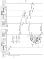
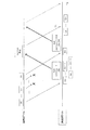
- FIG. 5 is a sequence diagram illustrating an example of a communication method. Processing performed in the communication device 10a and the communication device 10b will be described separately in (A) to (E) of FIG.
- the communication device 10 a transmits and receives TCP packets to and from the terminal 1
- the communication device 10 b transmits and receives TCP packets to and from the server 4.
- the case where the communication apparatus 10a transmits data toward the communication apparatus 10b is taken as an example.
- the communication device 10a and the communication device 10b communicate using a dedicated line installed in the WAN 2. Furthermore, in order to make it easier to understand which operation is performed by the communication device 10a or the communication device 10b, it is included in the number of the communication device 10 performing the processing after the part number in the communication device 10. The alphabet is written.
- the measurement unit 21a is the measurement unit 21 included in the communication device 10a
- the reception packet management unit 17b is the reception packet management unit 17 included in the communication device 10b.
- the terminal 1 transmits data addressed to the server 4 to the communication device 10a.
- the communication between the terminal 1 and the communication device 10a is performed using the TCP protocol as shown in (a1) of FIG. 5, and a confirmation response and a retransmission process are appropriately performed.
- an identification number TCP application identifier
- Allocate for a connection.
- the measuring unit 21a of the communication device 10a resets the length of a period during which no packet is received to 0 each time the communication device 10a receives a packet from the terminal 1.
- the selection unit 22a of the transmission-side communication device 10a acquires the packet P0 from the transmission / reception unit 13a and creates a transmission table ((a2) and (a3) in FIG. 5).
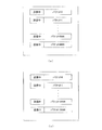
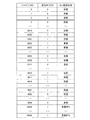
- FIG. 6A shows an example of a transmission table.
- the transmission table holds packets received from the terminal 1.
- the transmission / reception unit 13a outputs the packet P0 to the selection unit 22a.
- the selection unit 22a adds a flag indicating that transmission is in progress to the packet P0.
- a flag indicating that transmission is in progress may be referred to as a “transmission flag”.
- the selection unit 22a assigns a sequence ID to each packet received from the terminal 1 as an identifier indicating the order of packets received via the same connection for each TCP application identifier.
- the selection unit 22a sets the sequence ID of the packet first received via the connection identified by the TCP application identifier to 0, and assigns the sequence ID so that the order of the received packet is obtained.
- the sequence number of the first packet transmitted from the terminal 1 is 0 will be described as an example for easy understanding. Therefore, in the following example, the sequence number in the TCP header of the packet and the sequence ID assigned to the packet have the same value.
- the selection unit 22a generates a hash table using the sequence ID assigned to the packet P0 as a key, and stores the packet P0. Further, the selection unit 22a outputs the packet P0 input from the transmission / reception unit 13a to the transfer processing unit 14a in association with the TCP application identifier and the sequence ID.
- the selection unit 22a processes the packets P0 to P9999 to provide a hash table storing the information shown in FIG. Further, the selection unit 22a outputs the packets P0 to P9999 to the transfer processing unit 14a.
- the transfer processing unit 14a converts the packet input from the selection unit 22a into a transfer packet ((a4) in FIG. 5).
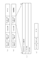
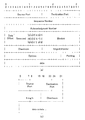
- FIG. 7 is a diagram showing an example of a packet format.
- FIG. 7 shows an example of packets transmitted and received between the communication device 10a and the communication device 10b.
- a packet used for data transmission / reception between the communication device 10a and the communication device 10b may be referred to as a “transfer packet”.
- FIG. 7A is an example of a packet format used for data transfer.
- a transfer packet used for data transfer includes an Internet Protocol (IP) header, a User Datagram Protocol (UDP) header, protocol ID information, a data header, and data.
- IP Internet Protocol
- UDP User Datagram Protocol
- the formats of the IP header and the UDP header are as defined by each protocol.
- the protocol ID stores information for determining whether the transfer packet is used for data transfer or data retransmission.
- the data header includes a TCP application identifier, a sequence ID, and a packet ID as shown in FIG. Data is data transmitted by a transfer packet.
- FIG. 7D is a diagram illustrating an example of a packet input from the selection unit 22a to the transfer processing unit 14a.
- a packet input from the selection unit 22a to the transfer processing unit 14a includes an IP header, a TCP header, and data.
- the transfer processing unit 14a does not change the IP header of the packet input from the selection unit 22a.
- the TCP header includes a source port number, a destination port number, a sequence number, an acknowledgment number, a data offset, a reserved area, a control bit, a window size, a checksum, an urgent pointer, and options.
- the UDP header includes a source port number, a destination port number, a segment size, and a checksum as shown in FIG.
- the transfer processing unit 14a acquires the source port number, the destination port number, and the sequence number from the TCP header of the packet P0.
- the transfer processing unit 14a sets the acquired source port number and destination port number as the source port number and destination port number in the UDP header of the transfer packet.
- the transfer processing unit 14a includes the identifier and sequence ID of the TCP application notified from the selection unit 22a in the data header.
- the transfer processing unit 14 records the sequence number included in the TCP header of the packet received from the terminal 1 as a packet ID in the data header.
- the transfer processing unit 14a sets the protocol ID to a value representing data transfer.
- the transfer processing unit 14a uses the data of the packet P0 as the data of the transfer packet, and sets the segment size and the checksum. Through the above processing, the transfer processing unit 14a converts the packet P0 into a transfer packet including data transmitted by the packet P0.
- the transfer processing unit 14a outputs the generated transfer packet to the transmission unit 11a ((a5) in FIG. 5).
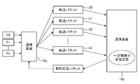
- FIG. 9 shows an example of packet transmission / reception between the communication device 10a and the communication device 10b.
- the transmission unit 11a transmits the transfer packet input from the transfer processing unit 14a to the communication device 10b ((a6) in FIG. 5).
- the selection unit 22a stores the time when the transmission unit 11a transmits the transfer packet as the final transmission time.
- the transfer packet (U0) in FIG. 9 represents a transfer packet converted from the packet P0.
- the conversion processing in the transfer processing unit 14a and the transmission processing from the transmission unit 11a are performed in the same manner as the packet P0.
- FIG. 9 shows an example of packet transmission / reception between the communication device 10a and the communication device 10b.
- each packet transmitted from the communication device 10a to the communication device 10b is a transfer packet to which a sequence ID having the same value as the number following U is attached.
- the selection unit 22a updates the final transmission time to a new transmission time each time a transfer packet is transmitted from the communication device 10a.
- the communication device 10b receives a transfer packet from the communication device 10a ((b1) in FIG. 5).
- the receiving unit 12b of the communication device 10b outputs the received packet to the packet processing unit 16b ((b2) in FIG. 5).
- the packet processing unit 16b extracts the sequence ID and the TCP application identifier from the data header in the input transfer packet, and outputs the obtained value to the received packet management unit 17b.
- the packet processing unit 16b generates a TCP header including information in the UDP header of the transfer packet and a packet ID in the data header.
- the packet processing unit 16b uses the packet ID as a sequence number in the TCP header.
- the packet processing unit 16b sets the source port number and destination port number in the UDP header to the source port number and destination port number in the TCP header.
- the packet processing unit 16b generates a TCP packet including information transmitted from the terminal 1 by removing the UDP header, the protocol ID, and the data header from the transfer packet and including the generated TCP header instead of these pieces of information. ((B4) of FIG. 5).
- a TCP packet including information transmitted in the packet P0 is generated from the transfer packet U0.
- the packet processing unit 16b outputs the generated packet to the transmission / reception unit 13b.
- the transmission / reception unit 13b transmits the packet input from the packet processing unit 16b to the server 4 ((b5) in FIG. 5).
- the communication device 10b processes other received transfer packets in the same manner. For this reason, the information included in the transfer packet that the communication device 10 b can receive from the communication device 10 a is transmitted to the server 4. Furthermore, the bandwidth calculation unit 18b calculates the bandwidth used for receiving the packet.
- the received packet management unit 17b stores a sequence ID included in a packet that the communication device 10b can receive from the communication device 10a.
- the communication device 10b can hold a table (reception table) that records the sequence ID of the received packet ((b3) in FIG. 5).
- the communication apparatus 10b has successfully received packets with sequence IDs 0 to 8019, 8024 to 8699, 8701 to 9009, and 9022 to 9999.
- the received packet management unit 17b stores the sequence ID of a packet that has been successfully received.
- a packet used for notification of control information includes an IP header, a UDP header, protocol ID information, a data header, and control information.
- the protocol ID information is set to Ack, and information specifying a packet that has been successfully received is recorded in the control information.
- FIG. 10 is a diagram illustrating an example of information included in the control information of the control response packet.
- the control information in the control response packet includes a control information identifier, reception size, maximum reception size, reception bandwidth, response request information, retransmission start ID, and retransmission start sequence length.
- the control information identifier is a TCP application identifier included in the packet for which the reception status is to be reported.
- the reception size is a value indicating, in bytes, the total amount of data obtained up to the end of a packet that has been successfully received continuously among packets having the same TCP application identifier. When the reception size is divided by the size of the payload in one transfer packet, the maximum value of sequence IDs that can be continuously received is obtained.
- the size of the payload in the transfer packet is set in advance in the communication device 10a and the communication device 10b.
- the maximum reception size is the product of the maximum value of the sequence ID attached to a packet that has been successfully received and the number of bytes of the payload of the transfer packet.
- the reception band is a bandwidth used by the communication device 10b for receiving a transfer packet from the communication device 10a.
- the bandwidth calculation unit 18b calculates the reception bandwidth of the communication device 10b.
- the retransmission start ID and retransmission start sequence length are used in combination.
- the retransmission start ID is a value that becomes the minimum sequence ID in each group when the packet that the communication device 10b has failed to receive is divided into groups with sequential IDs.
- the retransmission start sequence length is the number of packets that failed to be received that belong to the group having the retransmission start ID as a minimum value.
- the response request information is a value indicating whether an Ack for the packet is requested. In the case of the retransmission-based transmission method, the response request information is set to a value indicating that Ack is requested. On the other hand, the response request information is set to a value indicating that Ack is not requested in error correction-based retransmission, a control packet for notifying Ack, and the like.
- FIG. 10 is an example of control information in a control response packet generated by the communication device 10b.
- the communication device 10b has successfully received packets having sequence IDs 0 to 8019, 8024 to 8699, 8701 to 9009, and 9022 to 9999. For this reason, the received packet management unit 17b of the communication device 10b generates a control response packet for requesting the communication device 10a to retransmit the packets assigned the sequence IDs 8020 to 8023, 8700, and 9010 to 9021.
- the reception packet management unit 17b sets the reception size to 8019 ⁇ U and the maximum reception size to 10000 ⁇ U.
- U is the payload length of the transfer packet.
- the received packet management unit 17b adds an IP header specifying the destination as the communication device 10a and the transmission source as the communication device 10b to the control response packet. Furthermore, the received packet management unit 17b also sets a UDP header, a data header, and the like as appropriate, and includes information indicating that it is a control response packet in the protocol ID. The reception packet management unit 17b outputs the generated control response packet to the transmission unit 11b. The transmitter 11b transmits the input control response packet to the communication device 10a ((c2) in FIG. 5).
- the receiving unit 12a of the communication device 10a receives the control response packet including the information described with reference to FIG.
- the receiving unit 12a outputs the control response packet to the packet processing unit 16a ((d1) in FIG. 5). If the value of the protocol ID is information indicating that the packet is a control response packet, the packet processing unit 16a outputs the input packet to the selection unit 22a.
- the selection unit 22a updates the information on the packet being transmitted according to the reception status at the communication device 10b.
- FIG. 11 shows an example of updating the transmission table.
- the selection unit 22a deletes information on a packet that has been confirmed to have been successfully transmitted from the control response packet. For example, when the control response packet including the information shown in FIG. 10 is received, the selection unit 22a determines that transmission of packets having sequence IDs 0 to 8019, 8024 to 8699, 8701 to 9009, and 9022 to 9999 has been successful. On the other hand, the selection unit 22a determines that transmission of packets assigned with sequence IDs 8020 to 8023, 8700, and 9010 to 9021 has failed. Further, for the packets having the sequence ID of 10,000 to 19999, it is determined that the successful transmission status is not known because the control response packet has not been received. Therefore, by deleting the information of the packet determined to have been successfully transmitted, the information of the packet being transmitted is updated from the information shown in FIG. 6B to the information shown in FIG. 11 ((d2 in FIG. 5). )).
- FIG. 12 shows an example of a packet transmission pattern according to the type of transmission data.
- file transfer is performed, data transmission from the terminal 1 is continuously performed.
- the time interval when the communication apparatus 10a does not receive the packet from the terminal 1 is comparatively short.
- the communication device 10a continuously receives packets from the terminal 1.
- the transmission data is a moving image or the like, as shown in FIG. 12B, a period in which no packet is transmitted from the terminal 1 occurs according to the moving image frame rate. For this reason, when the moving image is transferred from the terminal 1, the period during which the communication device 10a does not receive a packet from the terminal 1 is longer than when the file transfer is performed.
- the communication device 10a When the communication device 10a does not receive a packet from the terminal 1, the communication device 10a does not transfer a new packet to the communication device 10b. Therefore, there is a possibility that an empty capacity is generated in the communication line between the communication device 10a and the communication device 10b. . Therefore, the communication device 10a retransmits, on an error correction basis, a packet whose transmission has not been confirmed due to the free capacity generated by not transferring a new packet.
- the method from determining whether to perform error correction based retransmission to the retransmission processing will be described in detail.
- the threshold value calculation unit 23a of the communication device 10a calculates a threshold value used for determining whether to perform error correction based retransmission.
- the selection unit 22a selects a packet to be retransmitted and notifies the threshold calculation unit 23a of the data amount of the selected packet.
- the selection unit 22a in addition to the packet notified that the transmission has failed, the selection unit 22a also sets a packet whose reception status is not notified by the control response packet as a retransmission target. Therefore, in the example described with reference to FIG. 11, the selection unit 22a sets the packets having sequence IDs 8020 to 8023, 8700, 9010 to 9021, and 10000 to 19999 as retransmission targets.
- the threshold value calculation unit 23a obtains the amount of redundant information to be transmitted when resending unacknowledged data on an error correction basis, using the time that can be transmitted with an unused bandwidth as a threshold value, and the obtained value Is sent to the selection unit 22a.
- the threshold calculation unit 23a calculates the threshold Th by the following equation.
- Th X ⁇ A / (BB used )
- X is a value indicating the total amount of data to be retransmitted in bytes.
- A is the ratio of the amount of data included in the redundant packet to be transmitted for error correction-based retransmission to the total amount of data to be retransmitted.
- A is arbitrarily set depending on the retransmission method, but can be set to a value of about 0.1 to 0.2, for example.
- B is the bandwidth of the line connecting the communication device 10a and the communication device 10b. Note that the threshold value calculation unit 23a stores the value A and the bandwidth (B) in advance or reads them from the memory 32a.
- B used is a bandwidth used for communication between the communication device 10a and the communication device 10b, and a value notified from the communication device 10b by a control response packet is used. Therefore, (BB used ) is a bandwidth of an unused bandwidth that is not used for communication between the communication device 10a and the communication device 10b.
- the selection unit 22a acquires a value of a period during which the communication device 10a has not received a packet from the terminal 1 from the measurement unit 21a, and compares it with the threshold Th. Here, it is assumed that the period during which the communication device 10a does not receive a packet from the terminal 1 exceeds the threshold Th. Then, the selection unit 22a determines that error correction-based retransmission processing is possible ((e1) in FIG. 5).
- the selection unit 22a outputs a packet to be retransmitted to the retransmission processing unit 15a.
- the retransmission processing unit 15a makes the data included in the packet input from the selection unit 22a redundant so that error correction can be performed. For example, the retransmission processing unit 15a generates a redundant packet used for error correction by forward-error-correction (FEC) encoding of the packet data input from the selection unit 22a. Further, the retransmission processing unit 15a adds header information to each packet and each redundant packet. The retransmission processing unit 15a adds header information in the same procedure as when the transfer processing unit 14a generates a transfer packet.
- FEC forward-error-correction
- the retransmission processing unit 15a records information indicating that the packet is an error correction based retransmission packet in the protocol ID information.
- the retransmission processing unit 15a outputs the generated packet to the transmission unit 11a ((e2) in FIG. 5).
- the transmission unit 11a transmits the packet input from the retransmission processing unit 15a to the communication device 10b ((e3) in FIG. 5).
- the selection unit 22a deletes the packet transmitted on the error correction basis from the retransmission processing unit 15a from the transmission table.
- FIG. 13 shows an example of processing of the communication apparatus according to the embodiment.
- the communication device 10a While receiving the TCP packet from the terminal 1, the communication device 10a converts the received packet into a UDP packet and transmits it to the communication device 10b.
- the communication device 10a receives the control response packet (Ack) including the information of the reception table generated by the reception packet management unit 17b of the communication device 10b at a predetermined cycle, and performs a retransmission process according to the control response packet.
- the communication device 10a performs retransmission while receiving the TCP packet from the terminal 1, the communication device 10a retransmits the packet that failed to be transmitted on a retransmission basis.
- the selection unit 22a of the communication apparatus 10a determines that a new packet is not transferred between the communication apparatus 10a and the communication apparatus 10b. Is determined to be free. For this reason, the selection unit 22a selects a packet whose reception has not been confirmed, and outputs the packet to the retransmission processing unit 15a.
- the retransmission processing unit 15a uses FEC encoding to convert the packet input from the selection unit 22a into a format in which error correction is possible, and performs retransmission processing.
- the communication device 10a again transfers the packet by a communication method that does not use the redundant packet.
- FIG. 14 is a flowchart for explaining an example of processing of the communication apparatus.
- the measurement unit 21 approximates the difference between the time when the transmission from the transmission unit 11 was last performed (final transmission time) and the current time, as a period during which the communication device 10 does not receive a packet from the terminal 1. Treated as a value.
- the measurement unit 21 holds a timer set to a value sufficiently shorter than the threshold Th, and requests the selection unit 22 to determine whether to perform error correction-based retransmission each time the timer expires. Shall.
- the processor 31 operating as the switching unit 20 or the packet processing unit 16 waits until an interrupt request is made (step S1). When there is an interrupt, the processor 31 determines the content requested by the interrupt (step S2). If the interrupt indicates reception of a TCP packet, the received packet from the terminal 1 is input to the selection unit 22a (step S3). Therefore, the selection unit 22 outputs the TCP packet to the transfer processing unit 14, and the transfer processing unit 14 converts the TCP packet into a transfer packet (step S4). The transfer processing unit 14 transfers the transfer packet to the receiving-side communication device 10 by the retransmission-based transfer method via the transmission unit 11 (step S5). The selection unit 22 updates the last transmission time to the current time (step S6).
- step S2 if the interrupt indicates reception of a UDP packet, a control response packet from the communication device 10 on the receiving side is input to the selection unit 22 (step S7).
- the selection unit 22 updates the transmission table using the control response packet (step S8). Further, since the Ack has not been received, the selection unit 22 updates the amount of packets to be retransmitted and the estimated value of the free bandwidth (step S9).
- the threshold calculation unit 23 calculates the threshold Th using the value of the free band (Step S10).
- step S2 If it is determined in step S2 that the interrupt is due to the time-up of the timer held by the measurement unit 21, the measurement unit 21 requests the selection unit 22 to determine whether to perform error correction-based retransmission processing ( Step S11). Therefore, the selection unit 22 acquires the current time (step S12). The selection unit 22 compares the time obtained by adding a threshold to the final transmission time with the current time (step S13). When the time obtained by adding the threshold value to the final transmission time is a time later than the current time, the time elapsed since the packet was last transferred to the communication device 10 on the receiving side is shorter than the threshold value.
- the selection unit 22 determines that the band with the communication device 10 on the reception side is not free to the extent that the error correction based retransmission can be performed, and returns to step S1 (No in step S13). ).
- the time obtained by adding a threshold value to the final transmission time is a time after the current time, the time elapsed since the packet was last transferred to the communication device 10 on the receiving side is equal to or more than the threshold value.
- the selection unit 22 determines that the band with the communication device 10 on the reception side is free to the extent that error correction based retransmission can be performed, and performs retransmission based on error correction based on the retransmission processing unit 15. (Yes in step S13).
- the retransmission processing unit 15 performs error correction based retransmission processing in response to a request from the selection unit 22. Further, the selection unit 22 updates the last transmission time to the current time (step S14).
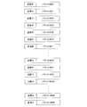
- FIG. 15 is a diagram for explaining an example of packet reception timing.
- the communication device 10a transmits the transfer packets U0 to Un to the communication device 10b by a retransmission-based transmission method.
- a control response packet generated when the communication device 10b receives the packet Ux-1 is transmitted from the communication device 10b to the communication device 10a.
- the selection unit 22a of the communication device 10a determines that Ux to Un are waiting for Ack, and leaves Ux to Un in the transmission table. .
- the communication device 10b cannot receive Ux to Un-1, but receives the packet Un. Then, the communication device 10b generates a control response packet for notifying that reception of the packets Un but Ux to Un-1 has failed, and transmits the control response packet to the communication device 10a.
- the selection unit 22a requests the retransmission processing unit 15a to retransmit Ux to Un on an error correction basis. Therefore, the communication device 10a retransmits Ux to Un to the communication device 10b on an error correction basis before receiving control response packets for Ux to Un. Therefore, the communication device 10b can receive Ux to Un at time T1.
- the control response packet for Ux to Un reaches the communication device 10a at the time when the round trip delay time (RTT) has elapsed from the time when the communication device 10a transmits Ux to Un.
- RTT round trip delay time
- the communication device 10a waits for the Ack from the communication device 10b while waiting for reception of the control response packet, and the RTT of the packet has failed for the first transmission failure. It will be forcibly retransmitted before doing. Therefore, since the packet can be forcibly retransmitted regardless of the RTT, a delay due to the length of the RTT is less likely to occur in the communication using the communication device 10a.
- the time when the communication device 10b receives Ux to Un-1 is the time It will be delayed to T2. Therefore, when the communication method according to the embodiment is used, the communication delay occurring between the communication device 10a and the communication device 10b can be reduced by the period of T2-T1. Further, the error correction based retransmission is performed when it is expected that there is a predetermined space or more in the line between the communication device 10a and the communication device 10b. For this reason, it is possible to prevent a decrease in throughput due to transmission of redundant packets.
- the bandwidth between the communication device 10a and the communication device 10b is M (bps)
- the redundancy by FEC is A
- the RTT between the communication device 10a and the communication device 10b is r (sec)
- the packet loss rate is d.
- the redundancy A is about 0.1
- the packet loss rate d is about 0.1 to 0.2.
- the throughput is Mbps.
- the expected value of latency is (r / 2) ⁇ (1 ⁇ d) + (r / 2 + r) ⁇ d.
- the throughput is M / (1 + A) bps, but the expected value of latency is (r / 2).
- the expected value of throughput is Mbps
- the expected value of latency is (r / 2). Therefore, by using the communication apparatus 10 to perform retransmission-based transfer and error correction-based retransmission, it is possible to suppress delay due to retransmission without reducing throughput.
- the threshold Th is shorter than the round-trip delay time (RTT) between the communication device 10a and the communication device 10b
- the calculated value of the threshold Th may exceed the RTT.
- the communication device 10a divides the retransmission processing of a packet whose transmission success has not been confirmed into a plurality of times, so that before the RTT between the communication device 10 on the transmission side and the reception side passes, Packets whose reception status at the communication device 10 cannot be confirmed can be forcibly retransmitted.
- the measurement unit 21 can also measure the time required for communication between the communication device 10a and the communication device 10b using the measurement packet.
- the measurement unit 21a generates a first measurement packet, and stores the time when the first measurement packet is transmitted from the transmission unit 11a to the communication device 10b.
- the first measurement packet is received by the reception unit 12b of the communication device 10b and is output to the measurement unit 21b.
- the receiving unit 12b stores the format of the measurement packet in advance and can distinguish the measurement packet from other packets.
- the measurement unit 21b generates a second measurement packet that responds to the first measurement packet, and transmits the second measurement packet to the communication device 10a via the transmission unit 11b.
- the reception unit 12a of the communication device 10a When receiving the second measurement packet, the reception unit 12a of the communication device 10a outputs the second measurement packet to the measurement unit 21a.
- the measurement unit 21a acquires the time when the second measurement packet is received, and calculates the difference from the transmission time of the first measurement packet.
- the measurement unit 21a outputs the obtained difference to the threshold value calculation unit 23a as RTT.
- the threshold value calculation unit 23a compares the threshold value Th and the RTT value. When the threshold value Th is equal to or greater than the RTT, the threshold value calculation unit 23a calculates the threshold value Thk instead of the threshold value Th. When the threshold value Thk is calculated, the threshold value Thk is used instead of the threshold value Th when determining whether to perform error correction-based retransmission processing.
- Y X / K.
- Y is the number of bytes of data to be transmitted in one error correction-based retransmission process.
- K is the number of retransmission processes performed on an error correction basis.
- X is the number of bytes of the total amount of data to be retransmitted
- A is the ratio of the amount of data included in the redundant packet to be transmitted for performing error correction based retransmission to the amount of data to be retransmitted It is.
- (BB used ) is a bandwidth of a free bandwidth that is not used for communication between the communication device 10a and the communication device 10b.
- the threshold calculation unit 23a can determine the number of retransmission processes according to the value of the threshold Th. For example, the threshold value calculation unit 23a can increase the value of K as the threshold value Th is longer, and can set an arbitrary integer of 2 or more to K according to the length of the threshold value Th. As described above, by dividing the error correction-based retransmission processing into a plurality of times, even if the amount of redundant data transmitted during the retransmission processing increases, the communication apparatus 10 receives Ack before the RTT elapses. Packets that have not been sent can be forcibly retransmitted. For this reason, since the distance between the communication device 10 on the transmission side and the communication device 10 on the reception side is increased, a delay in communication can be suppressed even if the RTT is increased.
- the amount of data transmitted at the time of one retransmission process is reduced, the amount of redundant packets used for one retransmission process can also be suppressed. For this reason, it becomes easy to avoid a situation in which the throughput decreases more than expected due to error correction-based retransmission.
- the transmission table is a hash table
- a table that records the transmission status of each packet and the reception status of Ack in association with the sequence ID may be used as the transmission table.
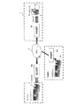
- FIG. 17 shows an example of a network.
- the communication device 10 may be used in a network including three or more communication devices 10.
- the threshold Thd is used in the determination by the selection unit 22.
- the threshold value Thd is obtained by the following equation.
- Thd X ⁇ A / Z
- Z is a value obtained by dividing a value obtained by subtracting the sum of bands used for communication from the bandwidth by the number of communication apparatuses 10 that can communicate with the communication apparatus 10 that is the transmission source.
- X is the number of bytes of data to be retransmitted, and A is the redundancy added by error correction.
- the line connected to the communication device 10a is the communication between the communication device 10a and the communication device 10b, and the communication device 10a and the communication device. It may be used for both communication between 10c. Therefore, from the bandwidth of the line connected to the communication device 10a, the bandwidth used for communication between the communication device 10a and the communication device 10b, and the bandwidth used for communication between the communication device 10a and the communication device 10c.
- the value obtained by subtracting the width and dividing by 2 is used as Z. In this way, by changing the threshold value used by the selection unit 22, in a network including an arbitrary number of communication devices 10 of 2 or more, communication is performed by combining two types of transmission methods, that is, retransmission base and error correction base. be able to.
- the RTT measurement method may be changed according to the implementation.
- the threshold Th is equal to or greater than the RTT, it is determined whether to perform retransmission using the threshold Thk, and in one retransmission process, 1 / K of a packet selected as a retransmission target is retransmitted
- the same processing may be performed even if the threshold Th is shorter than the RTT.
- Terminal 2 WAN DESCRIPTION OF SYMBOLS 3 Data center 4 Server 10
- Communication apparatus 11 Transmission part 12 Reception part 13 Transmission / reception part 14
- Transfer processing part 15 Retransmission processing part 16
- Packet processing part 17 Received packet management part 18
- Switching part 21 Measurement part 22 Selection part 23
- Threshold calculation Unit 31 Processor 32 Memory 33
- Input device 34 Output device 35
- Bus 36 External storage device 37
- Medium drive device 38 Portable storage medium 39
Landscapes
- Engineering & Computer Science (AREA)
- Computer Networks & Wireless Communication (AREA)
- Signal Processing (AREA)
- Environmental & Geological Engineering (AREA)
- Quality & Reliability (AREA)
- Communication Control (AREA)
- Data Exchanges In Wide-Area Networks (AREA)
- Detection And Prevention Of Errors In Transmission (AREA)
Abstract
Description
図2は、実施形態にかかる通信装置10が用いられるネットワークの例を示す。図2は、Wide Area Network(WAN)2をはさんで、端末1とデータセンタ3中のサーバ4が通信する場合のネットワークの例を示す。データセンタ3には、通信装置10bとサーバ4が含まれているものとする。また、端末1は、通信装置10aを介してWAN2にアクセスするものとする。ここで、通信装置10aおよび通信装置10bは、WAN高速化装置として動作することができるものとする。なお、端末1の数とデータセンタ3に含まれているサーバ4の数は任意である。
以下、図2に示すネットワークにおいて、端末1とサーバ4の間で通信が行われるケースでの通信装置10の処理を説明する。図5は、通信方法の例を示すシーケンス図であり、図5の(A)~(E)に分けて、通信装置10aおよび通信装置10bで行われる処理を説明する。以下の例では、通信装置10aは端末1との間でTCPパケットを送受信し、通信装置10bはサーバ4との間でTCPパケットを送受信する。また、通信装置10aが通信装置10bに向けてデータを送信する場合を例とする。さらに、第1の実施形態では、理解し易くするために、通信装置10aと通信装置10bは、WAN2に設置されている専用線を用いて通信しているものとする。さらに、通信装置10aと通信装置10bのいずれの動作であるかを分り易くするために、通信装置10中の部分の番号の後ろに、その処理を行っている通信装置10の番号に含まれているアルファベットを記載するものとする。例えば、計測部21aは通信装置10aに含まれている計測部21であり、受信パケット管理部17bは、通信装置10bに含まれている受信パケット管理部17である。
まず、端末1がサーバ4宛のデータを通信装置10aに送信する。端末1と通信装置10aの間の通信では、図5の(a1)に示すように、TCPプロトコルを用いて行われ、適宜、確認応答や再送処理が行われる。通信装置10aは、端末1との通信を開始するとき、TCP通信を行っている端末1を一意に認識するための識別番号(TCPアプリケーション識別子)を、端末1との間の通信で使用されるコネクションに対して割り振る。
通信装置10bは、通信装置10aから転送パケットを受信する(図5の(b1))。通信装置10bの受信部12bは、受信したパケットを、パケット処理部16bに出力する(図5の(b2))。パケット処理部16bは、入力された転送パケット中のデータヘッダからシーケンスIDとTCPアプリケーション識別子を抽出し、得られた値を受信パケット管理部17bに出力する。受信パケット管理部17bは、パケット処理部16bから入力された値を、通信装置10aから受信できたパケットのシーケンスIDとして、TCPアプリケーション識別子に対応付けて記憶する。転送パケットU0からは、シーケンスID=0が得られるので、受信パケット管理部17bは、シーケンスID=0のパケットの受信に成功したと認識する。
通信装置10bは、予め決められた周期ごとに、通信装置10aに制御応答パケット(Ack)を送信することにより、受信状況を通知する。制御情報の通知に使用されるパケットのフォーマットを、図7(b)に示す。制御情報の通知に使用されるパケットは、IPヘッダ、UDPヘッダ、プロトコルID情報、データヘッダ、制御情報を含む。制御応答パケットの場合、プロトコルID情報はAckに設定され、制御情報には、受信に成功したパケットを特定する情報が記録される。
通信装置10aは、シーケンスID=9999のパケットの送信後で、通信装置10bから制御応答パケットを受信する前に、シーケンスIDが10000~19999のパケットを通信装置10bに送信していたとする。すると、通信装置10bからの制御応答パケットを受信する前に選択部22aは、送信中のパケットの情報として、図6(b)に示す情報を保持している。
図12は、送信データの種類によるパケットの送信パターンの例を示す。ファイル転送が行われる場合、端末1からのデータの送信は連続的に行われる。このため、図12(a)に示すように、通信装置10aが端末1からのパケットを受信しない時間間隔は、比較的短い。言い換えると、通信装置10aは、端末1から連続的にパケットを受信する。一方、送信データが動画などである場合、図12(b)に示すように、動画フレームレートに応じて、パケットが端末1から送信されない期間が発生する。このため、端末1から動画が転送されている場合、通信装置10aが端末1からパケットを受信しない期間は、ファイル転送が行われている場合に比べて長い。
Th=X×A/(B-Bused)
ここで、Xは再送しようとするデータの総量をバイト単位で示す値である。Aは、誤り訂正ベースの再送を行うために送信する冗長分のパケットに含まれるデータ量が再送の対象とするデータの総量に対して占める割合である。Aは、再送方式によって任意に設定されるが、例えば、0.1~0.2程度の値に設定することができる。Bは、通信装置10aと通信装置10bの間を結ぶ回線の帯域幅である。なお、閾値計算部23aは、予め、Aの値と帯域幅(B)を記憶しているか、メモリ32aから読み出すものとする。Busedは、通信装置10aと通信装置10bの間の通信に使用されている帯域幅であり、制御応答パケットによって、通信装置10bから通知された値を用いる。従って、(B-Bused)は、通信装置10aと通信装置10bの間の通信に使用されていない空き帯域の帯域幅である。
第1の実施形態では、閾値Thが通信装置10aと通信装置10bの間の往復遅延時間(RTT)よりも短いケースを例として説明したが、閾値Thの計算値がRTTを超える場合もある。この場合、通信装置10aは、送信の成功が確認できていないパケットの再送処理を複数回に分けることにより、送信側と受信側の通信装置10の間のRTTが経過する前に、受信側の通信装置10での受信状況を確認できていないパケットを強制的に再送できる。
Thk=Y×A/(B-Bused)=X×A/K(B-Bused)=Th/K
ここで、Y=X/Kである。Yは、1回の誤り訂正ベースの再送処理で送信しようとするデータのバイト数である。Kは誤り訂正ベースで行う再送処理の回数である。また、Xは再送しようとするデータの総量のバイト数であり、Aは誤り訂正ベースの再送を行うために送信する冗長分のパケットに含まれるデータ量が再送するデータの量に対して占める割合である。(B-Bused)は、通信装置10aと通信装置10bの間の通信に使用されていない空き帯域の帯域幅である。
なお、実施形態は上記に限られるものではなく、様々に変形可能である。以下にその例をいくつか述べる。
Thd=X×A/Z
ここで、Zは、帯域幅から通信に使用されている帯域の総和を差し引いた値を、送信元の通信装置10と通信しうる通信装置10の数で割った値である。また、Xは再送しようとするデータのバイト数、Aは誤り訂正によって付加される冗長度である。
2 WAN
3 データセンタ
4 サーバ
10 通信装置
11 送信部
12 受信部
13 送受信部
14 転送処理部
15 再送処理部
16 パケット処理部
17 受信パケット管理部
18 帯域算出部
20 切り替え部
21 計測部
22 選択部
23 閾値計算部
31 プロセッサ
32 メモリ
33 入力装置
34 出力装置
35 バス
36 外部記憶装置
37 媒体駆動装置
38 可搬記憶媒体
39 ネットワーク接続装置
Claims (11)
- 第1の通信装置、第2の通信装置、および、第3の通信装置を含むネットワークにおいて、前記第2の通信装置は、
前記第1の通信装置から受信したパケットから、前記第3の通信装置に転送するパケットである転送パケットを特定し、
前記転送パケットを前記第1の通信装置から受信する間隔を計測し、
前記転送パケットを前記第3の通信装置に転送し、
前記転送パケットの受信状況を通知する通知情報を、前記第3の通信装置から受信し、
前記通知情報を用いて、前記第3の通信装置へ転送したパケットのうちで前記第3の通信装置から受信の成功が通知されていないパケットである対象パケットを選択し、
前記第1の通信装置から前記転送パケットを受信する間隔が閾値を超えると、前記対象パケットを、誤り補正が可能な形式で前記第3の通信装置に再送信する
ことを特徴とする通信方法。 - 前記対象パケットは、前記第3の通信装置から受信状況が通知されていないパケットと、前記第3の通信装置からパケットの受信の失敗を通知されたパケットを含む
ことを特徴とする請求項1に記載の通信方法。 - 前記第2の通信装置は、前記対象パケットを前記誤り訂正が可能な形式で送信するために用いる冗長分のデータを、前記第2の通信装置と前記第3の通信装置の間の回線中の使用されていない帯域幅を用いて、前記第2の通信装置が前記第3の通信装置に送信するためにかかる時間を、前記閾値として計算する
ことを特徴とする請求項1または2に記載の通信方法。 - 前記第2の通信装置は、
前記第2の通信装置が第1のパケットを前記第3の通信装置に向けて送信した時刻から、前記第1のパケットについての応答である第2のパケットが前記第2の通信装置に到達するまでの時間である応答時間を求め、
前記閾値が、前記応答時間を越えているかを判定し、
前記閾値が前記応答時間を超えている場合、前記閾値を第1の値で割って得られる商が前記応答時間よりも短くなるように、前記第1の値を求め、
前記対象パケットを前記誤り訂正が可能な形式で送信するために用いる冗長分のデータの量を前記第1の値で割って得られるデータ量である第2の値を求め、
前記第2の値のデータ量を、前記第2の通信装置と前記第3の通信装置の間の回線中の使用されていない帯域幅を用いて、前記第2の通信装置が前記第3の通信装置に送信するためにかかる時間の長さを第3の値とし、
前記第1の通信装置から前記転送パケットを受信する間隔が前記第3の値を超えると、前記対象パケットを前記第1の値と同数のグループに分けて得られる1つのグループに含まれるパケットを、誤り補正が可能な形式で前記第3の通信装置に再送信する
ことを特徴とする請求項3に記載の通信方法。 - 端末からパケットを受信する受信部と、
前記端末の通信先に向けて転送するパケットである転送パケットを受信する間隔を計測する計測部と、
前記転送パケットを、前記通信先に向けて転送する転送処理部と、
前記通信先へ転送したパケットのうちで前記通信先から受信の成功が通知されていないパケットである対象パケットを選択する選択部と、
前記転送パケットの受信間隔が閾値を超えると、前記対象パケットを、誤り補正が可能な形式で前記通信先に再送信するための処理を行う再送処理部
を備えることを特徴とする通信装置。 - 前記選択部は、前記通信先からの受信状況の通知を受信していないパケットと、前記通信先からパケットの受信の失敗を通知されたパケットを、前記対象パケットとして選択する
ことを特徴とする請求項5に記載の通信装置。 - 前記対象パケットを前記誤り訂正が可能な形式で送信するために用いる冗長分のデータを、前記通信装置と前記通信先の間の回線中の使用されていない帯域幅を用いて、前記通信装置が前記通信先に送信するためにかかる時間を、前記閾値として計算する計算部
をさらに備えることを特徴とする請求項5または6に記載の通信装置。 - 第1の通信装置、第2の通信装置、および第3の通信装置を含むネットワーク中の前記第2の通信装置に、
前記第1の通信装置から受信したパケットから、前記第3の通信装置に転送するパケットである転送パケットを特定し、
前記転送パケットを前記第1の通信装置から受信する間隔を計測し、
前記転送パケットを前記第3の通信装置に転送し、
前記転送パケットの受信状況を通知する通知情報を、前記第3の通信装置から受信し、
前記通知情報を用いて、前記第3の通信装置へ転送したパケットのうちで前記第3の通信装置から受信の成功が通知されていないパケットである対象パケットを選択し、
前記第1の通信装置から前記転送パケットを受信する間隔が閾値を超えると、前記対象パケットを、誤り補正が可能な形式で前記第3の通信装置に再送信する
処理を行わせることを特徴とする通信プログラム。 - 前記対象パケットは、前記第3の通信装置から受信状況が通知されていないパケットと、前記第3の通信装置からパケットの受信の失敗を通知されたパケットを含む
ことを特徴とする請求項8に記載の通信プログラム。 - 前記第2の通信装置は、前記対象パケットを前記誤り訂正が可能な形式で送信するために用いる冗長分のデータを、前記第2の通信装置と前記第3の通信装置の間の回線中の使用されていない帯域幅を用いて、前記第2の通信装置が前記第3の通信装置に送信するためにかかる時間を、前記閾値として計算する
ことを特徴とする請求項8または9に記載の通信プログラム。 - 前記第2の通信装置に、
前記第2の通信装置が第1のパケットを前記第3の通信装置に向けて送信した時刻から、前記第1のパケットについての応答である第2のパケットが前記第2の通信装置に到達するまでの時間である応答時間を求め、
前記閾値が、前記応答時間を越えているかを判定し、
前記閾値が前記応答時間を超えている場合、前記閾値を第1の値で割って得られる商が前記応答時間よりも短くなるように、前記第1の値を求め、
前記対象パケットを前記誤り訂正が可能な形式で送信するために用いる冗長分のデータの量を前記第1の値で割って得られるデータ量である第2の値を求め、
前記第2の値のデータ量を、前記第2の通信装置と前記第3の通信装置の間の回線中の使用されていない帯域幅を用いて、前記第2の通信装置が前記第3の通信装置に送信するためにかかる時間の長さを第3の値とし、
前記第1の通信装置から前記転送パケットを受信する間隔が前記第3の値を超えると、前記対象パケットを前記第1の値と同数のグループに分けて得られる1つのグループに含まれるパケットを、誤り補正が可能な形式で前記第3の通信装置に再送信する
処理をさらに行わせることを特徴とする請求項10に記載の通信プログラム。
Priority Applications (5)
| Application Number | Priority Date | Filing Date | Title |
|---|---|---|---|
| PCT/JP2013/057920 WO2014147774A1 (ja) | 2013-03-20 | 2013-03-20 | 通信方法、通信装置、および、通信プログラム |
| CN201380073730.8A CN105103500A (zh) | 2013-03-20 | 2013-03-20 | 通信方法、通信装置以及通信程序 |
| JP2015506469A JP5935940B2 (ja) | 2013-03-20 | 2013-03-20 | 通信方法、通信装置、および、通信プログラム |
| EP13878896.3A EP2978171B1 (en) | 2013-03-20 | 2013-03-20 | Communication method, communication device, and communication program |
| US14/822,220 US9866351B2 (en) | 2013-03-20 | 2015-08-10 | Communication method and communication apparatus |
Applications Claiming Priority (1)
| Application Number | Priority Date | Filing Date | Title |
|---|---|---|---|
| PCT/JP2013/057920 WO2014147774A1 (ja) | 2013-03-20 | 2013-03-20 | 通信方法、通信装置、および、通信プログラム |
Related Child Applications (1)
| Application Number | Title | Priority Date | Filing Date |
|---|---|---|---|
| US14/822,220 Continuation US9866351B2 (en) | 2013-03-20 | 2015-08-10 | Communication method and communication apparatus |
Publications (1)
| Publication Number | Publication Date |
|---|---|
| WO2014147774A1 true WO2014147774A1 (ja) | 2014-09-25 |
Family
ID=51579506
Family Applications (1)
| Application Number | Title | Priority Date | Filing Date |
|---|---|---|---|
| PCT/JP2013/057920 Ceased WO2014147774A1 (ja) | 2013-03-20 | 2013-03-20 | 通信方法、通信装置、および、通信プログラム |
Country Status (5)
| Country | Link |
|---|---|
| US (1) | US9866351B2 (ja) |
| EP (1) | EP2978171B1 (ja) |
| JP (1) | JP5935940B2 (ja) |
| CN (1) | CN105103500A (ja) |
| WO (1) | WO2014147774A1 (ja) |
Cited By (1)
| Publication number | Priority date | Publication date | Assignee | Title |
|---|---|---|---|---|
| CN110876186A (zh) * | 2018-08-29 | 2020-03-10 | 苹果公司 | 针对非基于触发器的测距的功率节省 |
Families Citing this family (11)
| Publication number | Priority date | Publication date | Assignee | Title |
|---|---|---|---|---|
| AU2014413360C1 (en) * | 2014-12-12 | 2018-09-27 | Hitachi, Ltd. | Communication device, communication device system, and communication method |
| US10165530B2 (en) * | 2016-03-22 | 2018-12-25 | Christoph RULAND | Verification of time information transmitted by time signals or time telegrams |
| US10841833B2 (en) | 2016-10-12 | 2020-11-17 | Qualcomm Incorporated | Streamlined user plane headers for high data rates |
| US10374762B2 (en) * | 2017-02-28 | 2019-08-06 | At&T Intellectual Property I, L.P. | Use of underutilized bandwidth via radio access resource sharing |
| US11140589B2 (en) * | 2017-08-08 | 2021-10-05 | Lg Electronics, Inc | Method and apparatus for handling failure of early data transmission in wireless communication system |
| CN108462707B (zh) * | 2018-03-13 | 2020-08-28 | 中山大学 | 一种基于深度学习序列分析的移动应用识别方法 |
| CN110971942B (zh) * | 2018-09-28 | 2021-08-17 | 杭州海康威视数字技术股份有限公司 | 数据传输方法和装置 |
| US10757166B2 (en) * | 2018-11-20 | 2020-08-25 | International Business Machines Corporation | Passive re-assembly of HTTP2 fragmented segments |
| WO2020034576A1 (en) * | 2019-01-11 | 2020-02-20 | Zte Corporation | Timing adjustments for data transmission in wireless systems |
| JP7499035B2 (ja) * | 2020-01-30 | 2024-06-13 | 株式会社Preferred Networks | 通信装置及び通信方法 |
| CN112181883B (zh) * | 2020-09-24 | 2022-11-08 | 深圳市乐唯科技开发有限公司 | 一种串口通讯的数据传输方法、系统及存储介质 |
Citations (5)
| Publication number | Priority date | Publication date | Assignee | Title |
|---|---|---|---|---|
| JP2002507369A (ja) | 1997-07-03 | 2002-03-05 | シーメンス アクチエンゲゼルシヤフト | ディジタルデータの符号化方法および符号化装置 |
| WO2007007383A1 (ja) * | 2005-07-08 | 2007-01-18 | Fujitsu Limited | 送信装置、受信装置、情報通信方法 |
| WO2007061087A1 (ja) | 2005-11-28 | 2007-05-31 | Nec Corporation | 通信装置、通信システム、通信方法、および、通信プログラム |
| JP2010098766A (ja) * | 2010-01-18 | 2010-04-30 | Fujitsu Ltd | 受信装置、受信方法、無線通信システム、及び通信方法 |
| JP2012004952A (ja) * | 2010-06-18 | 2012-01-05 | Fujitsu Ltd | データ転送装置、データ転送方法及びデータ転送プログラム |
Family Cites Families (11)
| Publication number | Priority date | Publication date | Assignee | Title |
|---|---|---|---|---|
| JP3757857B2 (ja) * | 2001-12-12 | 2006-03-22 | ソニー株式会社 | データ通信システム、データ送信装置、データ受信装置、および方法、並びにコンピュータ・プログラム |
| BRPI0516632A (pt) * | 2004-12-02 | 2008-09-16 | Thomson Licensing | correção de erros antecipada e adaptativa |
| US7937640B2 (en) * | 2006-12-18 | 2011-05-03 | At&T Intellectual Property I, L.P. | Video over IP network transmission system |
| US8112687B2 (en) * | 2008-01-03 | 2012-02-07 | Ikanos Communications, Inc. | Systems and methods for mitigating impulse noise |
| CA2765663C (en) * | 2009-06-19 | 2017-06-06 | Research In Motion Limited | Uplink transmissions for type 2 relay |
| JP5685307B2 (ja) * | 2010-03-29 | 2015-03-18 | エルジー エレクトロニクス インコーポレイティド | アップリンク多重アンテナ伝送を支援するための効率的な制御情報伝送方法及び装置 |
| US8948252B2 (en) * | 2010-03-30 | 2015-02-03 | Sony Corporation | Moving picture transmission apparatus, moving picture transmission system, moving picture transmission method, and program |
| US8976744B2 (en) * | 2010-11-03 | 2015-03-10 | Broadcom Corporation | Vehicle communication network including wireless communications |
| US9571178B2 (en) * | 2011-04-19 | 2017-02-14 | Lg Electronics Inc. | Method and apparatus for transmitting and receiving data in a wireless communication system that supports a relay node |
| WO2014014165A1 (en) * | 2012-07-15 | 2014-01-23 | Lg Electronics Inc. | Method for transmitting downlink signal at a relay node in a wireless communication system and appatatus therefor |
| US9729270B2 (en) * | 2013-03-12 | 2017-08-08 | Empire Technology Development Llc | Self-adaptively improving system stability |
-
2013
- 2013-03-20 WO PCT/JP2013/057920 patent/WO2014147774A1/ja not_active Ceased
- 2013-03-20 CN CN201380073730.8A patent/CN105103500A/zh active Pending
- 2013-03-20 EP EP13878896.3A patent/EP2978171B1/en not_active Not-in-force
- 2013-03-20 JP JP2015506469A patent/JP5935940B2/ja not_active Expired - Fee Related
-
2015
- 2015-08-10 US US14/822,220 patent/US9866351B2/en not_active Expired - Fee Related
Patent Citations (5)
| Publication number | Priority date | Publication date | Assignee | Title |
|---|---|---|---|---|
| JP2002507369A (ja) | 1997-07-03 | 2002-03-05 | シーメンス アクチエンゲゼルシヤフト | ディジタルデータの符号化方法および符号化装置 |
| WO2007007383A1 (ja) * | 2005-07-08 | 2007-01-18 | Fujitsu Limited | 送信装置、受信装置、情報通信方法 |
| WO2007061087A1 (ja) | 2005-11-28 | 2007-05-31 | Nec Corporation | 通信装置、通信システム、通信方法、および、通信プログラム |
| JP2010098766A (ja) * | 2010-01-18 | 2010-04-30 | Fujitsu Ltd | 受信装置、受信方法、無線通信システム、及び通信方法 |
| JP2012004952A (ja) * | 2010-06-18 | 2012-01-05 | Fujitsu Ltd | データ転送装置、データ転送方法及びデータ転送プログラム |
Non-Patent Citations (1)
| Title |
|---|
| See also references of EP2978171A4 |
Cited By (2)
| Publication number | Priority date | Publication date | Assignee | Title |
|---|---|---|---|---|
| CN110876186A (zh) * | 2018-08-29 | 2020-03-10 | 苹果公司 | 针对非基于触发器的测距的功率节省 |
| CN110876186B (zh) * | 2018-08-29 | 2023-09-05 | 苹果公司 | 针对非基于触发器的测距的功率节省 |
Also Published As
| Publication number | Publication date |
|---|---|
| JPWO2014147774A1 (ja) | 2017-02-16 |
| US9866351B2 (en) | 2018-01-09 |
| US20150349930A1 (en) | 2015-12-03 |
| EP2978171A4 (en) | 2016-05-04 |
| JP5935940B2 (ja) | 2016-06-15 |
| EP2978171B1 (en) | 2017-09-20 |
| CN105103500A (zh) | 2015-11-25 |
| EP2978171A1 (en) | 2016-01-27 |
Similar Documents
| Publication | Publication Date | Title |
|---|---|---|
| JP5935940B2 (ja) | 通信方法、通信装置、および、通信プログラム | |
| EP2759164B1 (en) | Dynamic subflow control for a multipath transport connection in a wireless communication network | |
| JP5544430B2 (ja) | 通信装置および通信システム | |
| US9577791B2 (en) | Notification by network element of packet drops | |
| JP5867188B2 (ja) | 情報処理装置、輻輳制御方法および輻輳制御プログラム | |
| US20170149675A1 (en) | Packet retransmission method and apparatus | |
| CN115396077A (zh) | 一种数据传输方法及装置 | |
| JP6094357B2 (ja) | 通信方法、通信システム、及び通信装置 | |
| US9037935B2 (en) | Apparatus and method for retransmitting message in message transmission system | |
| US10439940B2 (en) | Latency correction between transport layer host and deterministic interface circuit | |
| JP2014524092A (ja) | 単一ソケットポイントツーマルチポイント性能による高信頼性仮想双方向データストリーム通信のためのシステムおよび方法 | |
| WO2014092779A1 (en) | Notification by network element of packet drops | |
| CN109981385B (zh) | 一种实现丢包检测的方法、装置和系统 | |
| JP2015027100A (ja) | パケット通信の伝送制御方法及びパケット通信システム | |
| JP2022505424A (ja) | パケット処理方法および装置 | |
| US10461886B2 (en) | Transport layer identifying failure cause and mitigation for deterministic transport across multiple deterministic data links | |
| US20230224084A1 (en) | Packet Retransmission Method and Apparatus | |
| CN103973414A (zh) | 一种数据传输方法及装置 | |
| CN104104608B (zh) | 接收报文的方法及装置 | |
| US20190132085A1 (en) | Fast Detection and Retransmission of Dropped Last Packet in a Flow | |
| US11962517B2 (en) | Communications method, apparatus, and system for recovering lost packets | |
| JP5998923B2 (ja) | プログラム、情報処理装置、及び通信方法 | |
| CN120110594A (zh) | 数据确认传输方法、网络设备及存储介质 | |
| US11811877B2 (en) | Universal transport framework for heterogeneous data streams | |
| EP3389206A1 (en) | Multipath error correction |
Legal Events
| Date | Code | Title | Description |
|---|---|---|---|
| WWE | Wipo information: entry into national phase |
Ref document number: 201380073730.8 Country of ref document: CN |
|
| 121 | Ep: the epo has been informed by wipo that ep was designated in this application |
Ref document number: 13878896 Country of ref document: EP Kind code of ref document: A1 |
|
| ENP | Entry into the national phase |
Ref document number: 2015506469 Country of ref document: JP Kind code of ref document: A |
|
| REEP | Request for entry into the european phase |
Ref document number: 2013878896 Country of ref document: EP |
|
| WWE | Wipo information: entry into national phase |
Ref document number: 2013878896 Country of ref document: EP |
|
| NENP | Non-entry into the national phase |
Ref country code: DE |