WO2014147904A1 - Unité de génération de puissance, et procédé de commande de moteur-générateur - Google Patents
Unité de génération de puissance, et procédé de commande de moteur-générateur Download PDFInfo
- Publication number
- WO2014147904A1 WO2014147904A1 PCT/JP2013/083254 JP2013083254W WO2014147904A1 WO 2014147904 A1 WO2014147904 A1 WO 2014147904A1 JP 2013083254 W JP2013083254 W JP 2013083254W WO 2014147904 A1 WO2014147904 A1 WO 2014147904A1
- Authority
- WO
- WIPO (PCT)
- Prior art keywords
- state
- coils
- phase
- generator
- phases
- Prior art date
- Legal status (The legal status is an assumption and is not a legal conclusion. Google has not performed a legal analysis and makes no representation as to the accuracy of the status listed.)
- Ceased
Links
Images







Classifications
-
- F—MECHANICAL ENGINEERING; LIGHTING; HEATING; WEAPONS; BLASTING
- F02—COMBUSTION ENGINES; HOT-GAS OR COMBUSTION-PRODUCT ENGINE PLANTS
- F02N—STARTING OF COMBUSTION ENGINES; STARTING AIDS FOR SUCH ENGINES, NOT OTHERWISE PROVIDED FOR
- F02N11/00—Starting of engines by means of electric motors
- F02N11/08—Circuits specially adapted for starting of engines
- F02N11/0814—Circuits specially adapted for starting of engines comprising means for controlling automatic idle-start-stop
-
- B—PERFORMING OPERATIONS; TRANSPORTING
- B60—VEHICLES IN GENERAL
- B60K—ARRANGEMENT OR MOUNTING OF PROPULSION UNITS OR OF TRANSMISSIONS IN VEHICLES; ARRANGEMENT OR MOUNTING OF PLURAL DIVERSE PRIME-MOVERS IN VEHICLES; AUXILIARY DRIVES FOR VEHICLES; INSTRUMENTATION OR DASHBOARDS FOR VEHICLES; ARRANGEMENTS IN CONNECTION WITH COOLING, AIR INTAKE, GAS EXHAUST OR FUEL SUPPLY OF PROPULSION UNITS IN VEHICLES
- B60K6/00—Arrangement or mounting of plural diverse prime-movers for mutual or common propulsion, e.g. hybrid propulsion systems comprising electric motors and internal combustion engines
- B60K6/20—Arrangement or mounting of plural diverse prime-movers for mutual or common propulsion, e.g. hybrid propulsion systems comprising electric motors and internal combustion engines the prime-movers consisting of electric motors and internal combustion engines, e.g. HEVs
- B60K6/22—Arrangement or mounting of plural diverse prime-movers for mutual or common propulsion, e.g. hybrid propulsion systems comprising electric motors and internal combustion engines the prime-movers consisting of electric motors and internal combustion engines, e.g. HEVs characterised by apparatus, components or means specially adapted for HEVs
- B60K6/26—Arrangement or mounting of plural diverse prime-movers for mutual or common propulsion, e.g. hybrid propulsion systems comprising electric motors and internal combustion engines the prime-movers consisting of electric motors and internal combustion engines, e.g. HEVs characterised by apparatus, components or means specially adapted for HEVs characterised by the motors or the generators
-
- B—PERFORMING OPERATIONS; TRANSPORTING
- B60—VEHICLES IN GENERAL
- B60K—ARRANGEMENT OR MOUNTING OF PROPULSION UNITS OR OF TRANSMISSIONS IN VEHICLES; ARRANGEMENT OR MOUNTING OF PLURAL DIVERSE PRIME-MOVERS IN VEHICLES; AUXILIARY DRIVES FOR VEHICLES; INSTRUMENTATION OR DASHBOARDS FOR VEHICLES; ARRANGEMENTS IN CONNECTION WITH COOLING, AIR INTAKE, GAS EXHAUST OR FUEL SUPPLY OF PROPULSION UNITS IN VEHICLES
- B60K6/00—Arrangement or mounting of plural diverse prime-movers for mutual or common propulsion, e.g. hybrid propulsion systems comprising electric motors and internal combustion engines
- B60K6/20—Arrangement or mounting of plural diverse prime-movers for mutual or common propulsion, e.g. hybrid propulsion systems comprising electric motors and internal combustion engines the prime-movers consisting of electric motors and internal combustion engines, e.g. HEVs
- B60K6/42—Arrangement or mounting of plural diverse prime-movers for mutual or common propulsion, e.g. hybrid propulsion systems comprising electric motors and internal combustion engines the prime-movers consisting of electric motors and internal combustion engines, e.g. HEVs characterised by the architecture of the hybrid electric vehicle
- B60K6/48—Parallel type
- B60K6/485—Motor-assist type
-
- F—MECHANICAL ENGINEERING; LIGHTING; HEATING; WEAPONS; BLASTING
- F02—COMBUSTION ENGINES; HOT-GAS OR COMBUSTION-PRODUCT ENGINE PLANTS
- F02B—INTERNAL-COMBUSTION PISTON ENGINES; COMBUSTION ENGINES IN GENERAL
- F02B61/00—Adaptations of engines for driving vehicles or for driving propellers; Combinations of engines with gearing
- F02B61/02—Adaptations of engines for driving vehicles or for driving propellers; Combinations of engines with gearing for driving cycles
-
- F—MECHANICAL ENGINEERING; LIGHTING; HEATING; WEAPONS; BLASTING
- F02—COMBUSTION ENGINES; HOT-GAS OR COMBUSTION-PRODUCT ENGINE PLANTS
- F02B—INTERNAL-COMBUSTION PISTON ENGINES; COMBUSTION ENGINES IN GENERAL
- F02B63/00—Adaptations of engines for driving pumps, hand-held tools or electric generators; Portable combinations of engines with engine-driven devices
- F02B63/04—Adaptations of engines for driving pumps, hand-held tools or electric generators; Portable combinations of engines with engine-driven devices for electric generators
-
- F—MECHANICAL ENGINEERING; LIGHTING; HEATING; WEAPONS; BLASTING
- F02—COMBUSTION ENGINES; HOT-GAS OR COMBUSTION-PRODUCT ENGINE PLANTS
- F02N—STARTING OF COMBUSTION ENGINES; STARTING AIDS FOR SUCH ENGINES, NOT OTHERWISE PROVIDED FOR
- F02N11/00—Starting of engines by means of electric motors
- F02N11/04—Starting of engines by means of electric motors the motors being associated with current generators
-
- F—MECHANICAL ENGINEERING; LIGHTING; HEATING; WEAPONS; BLASTING
- F02—COMBUSTION ENGINES; HOT-GAS OR COMBUSTION-PRODUCT ENGINE PLANTS
- F02N—STARTING OF COMBUSTION ENGINES; STARTING AIDS FOR SUCH ENGINES, NOT OTHERWISE PROVIDED FOR
- F02N11/00—Starting of engines by means of electric motors
- F02N11/08—Circuits specially adapted for starting of engines
- F02N11/0859—Circuits specially adapted for starting of engines specially adapted to the type of the starter motor or integrated into it
-
- H—ELECTRICITY
- H02—GENERATION; CONVERSION OR DISTRIBUTION OF ELECTRIC POWER
- H02J—ELECTRIC POWER NETWORKS; CIRCUIT ARRANGEMENTS OR SYSTEMS FOR SUPPLYING OR DISTRIBUTING ELECTRIC POWER; SYSTEMS FOR STORING ELECTRIC ENERGY
- H02J7/00—Circuit arrangements for charging or discharging batteries or for supplying loads from batteries
- H02J7/14—Circuit arrangements for charging or discharging batteries or for supplying loads from batteries for charging batteries from dynamo-electric generators driven at varying speed, e.g. on vehicle
- H02J7/1469—Regulation of the charging current or voltage otherwise than by variation of field
- H02J7/1484—Regulation of the charging current or voltage otherwise than by variation of field by commutation of the output windings of the generator
-
- H—ELECTRICITY
- H02—GENERATION; CONVERSION OR DISTRIBUTION OF ELECTRIC POWER
- H02J—ELECTRIC POWER NETWORKS; CIRCUIT ARRANGEMENTS OR SYSTEMS FOR SUPPLYING OR DISTRIBUTING ELECTRIC POWER; SYSTEMS FOR STORING ELECTRIC ENERGY
- H02J7/00—Circuit arrangements for charging or discharging batteries or for supplying loads from batteries
- H02J7/14—Circuit arrangements for charging or discharging batteries or for supplying loads from batteries for charging batteries from dynamo-electric generators driven at varying speed, e.g. on vehicle
- H02J7/16—Regulation of the charging current or voltage by variation of field
-
- H—ELECTRICITY
- H02—GENERATION; CONVERSION OR DISTRIBUTION OF ELECTRIC POWER
- H02K—DYNAMO-ELECTRIC MACHINES
- H02K21/00—Synchronous motors having permanent magnets; Synchronous generators having permanent magnets
- H02K21/12—Synchronous motors having permanent magnets; Synchronous generators having permanent magnets with stationary armatures and rotating magnets
- H02K21/22—Synchronous motors having permanent magnets; Synchronous generators having permanent magnets with stationary armatures and rotating magnets with magnets rotating around the armatures, e.g. flywheel magnetos
-
- H—ELECTRICITY
- H02—GENERATION; CONVERSION OR DISTRIBUTION OF ELECTRIC POWER
- H02P—CONTROL OR REGULATION OF ELECTRIC MOTORS, ELECTRIC GENERATORS OR DYNAMO-ELECTRIC CONVERTERS; CONTROLLING TRANSFORMERS, REACTORS OR CHOKE COILS
- H02P27/00—Arrangements or methods for the control of AC motors characterised by the kind of supply voltage
- H02P27/04—Arrangements or methods for the control of AC motors characterised by the kind of supply voltage using variable-frequency supply voltage, e.g. inverter or converter supply voltage
- H02P27/06—Arrangements or methods for the control of AC motors characterised by the kind of supply voltage using variable-frequency supply voltage, e.g. inverter or converter supply voltage using DC to AC converters or inverters
- H02P27/08—Arrangements or methods for the control of AC motors characterised by the kind of supply voltage using variable-frequency supply voltage, e.g. inverter or converter supply voltage using DC to AC converters or inverters with pulse width modulation
- H02P27/085—Arrangements or methods for the control of AC motors characterised by the kind of supply voltage using variable-frequency supply voltage, e.g. inverter or converter supply voltage using DC to AC converters or inverters with pulse width modulation wherein the PWM mode is adapted on the running conditions of the motor, e.g. the switching frequency
-
- H—ELECTRICITY
- H02—GENERATION; CONVERSION OR DISTRIBUTION OF ELECTRIC POWER
- H02P—CONTROL OR REGULATION OF ELECTRIC MOTORS, ELECTRIC GENERATORS OR DYNAMO-ELECTRIC CONVERTERS; CONTROLLING TRANSFORMERS, REACTORS OR CHOKE COILS
- H02P9/00—Arrangements for controlling electric generators for the purpose of obtaining a desired output
- H02P9/48—Arrangements for obtaining a constant output value at varying speed of the generator, e.g. on vehicle
-
- B—PERFORMING OPERATIONS; TRANSPORTING
- B60—VEHICLES IN GENERAL
- B60K—ARRANGEMENT OR MOUNTING OF PROPULSION UNITS OR OF TRANSMISSIONS IN VEHICLES; ARRANGEMENT OR MOUNTING OF PLURAL DIVERSE PRIME-MOVERS IN VEHICLES; AUXILIARY DRIVES FOR VEHICLES; INSTRUMENTATION OR DASHBOARDS FOR VEHICLES; ARRANGEMENTS IN CONNECTION WITH COOLING, AIR INTAKE, GAS EXHAUST OR FUEL SUPPLY OF PROPULSION UNITS IN VEHICLES
- B60K6/00—Arrangement or mounting of plural diverse prime-movers for mutual or common propulsion, e.g. hybrid propulsion systems comprising electric motors and internal combustion engines
- B60K6/20—Arrangement or mounting of plural diverse prime-movers for mutual or common propulsion, e.g. hybrid propulsion systems comprising electric motors and internal combustion engines the prime-movers consisting of electric motors and internal combustion engines, e.g. HEVs
- B60K6/22—Arrangement or mounting of plural diverse prime-movers for mutual or common propulsion, e.g. hybrid propulsion systems comprising electric motors and internal combustion engines the prime-movers consisting of electric motors and internal combustion engines, e.g. HEVs characterised by apparatus, components or means specially adapted for HEVs
- B60K6/26—Arrangement or mounting of plural diverse prime-movers for mutual or common propulsion, e.g. hybrid propulsion systems comprising electric motors and internal combustion engines the prime-movers consisting of electric motors and internal combustion engines, e.g. HEVs characterised by apparatus, components or means specially adapted for HEVs characterised by the motors or the generators
- B60K2006/264—Arrangement or mounting of plural diverse prime-movers for mutual or common propulsion, e.g. hybrid propulsion systems comprising electric motors and internal combustion engines the prime-movers consisting of electric motors and internal combustion engines, e.g. HEVs characterised by apparatus, components or means specially adapted for HEVs characterised by the motors or the generators with outer rotor and inner stator
-
- B—PERFORMING OPERATIONS; TRANSPORTING
- B60—VEHICLES IN GENERAL
- B60L—PROPULSION OF ELECTRICALLY-PROPELLED VEHICLES; SUPPLYING ELECTRIC POWER FOR AUXILIARY EQUIPMENT OF ELECTRICALLY-PROPELLED VEHICLES; ELECTRODYNAMIC BRAKE SYSTEMS FOR VEHICLES IN GENERAL; MAGNETIC SUSPENSION OR LEVITATION FOR VEHICLES; MONITORING OPERATING VARIABLES OF ELECTRICALLY-PROPELLED VEHICLES; ELECTRIC SAFETY DEVICES FOR ELECTRICALLY-PROPELLED VEHICLES
- B60L2220/00—Electrical machine types; Structures or applications thereof
- B60L2220/10—Electrical machine types
- B60L2220/14—Synchronous machines
-
- B—PERFORMING OPERATIONS; TRANSPORTING
- B60—VEHICLES IN GENERAL
- B60L—PROPULSION OF ELECTRICALLY-PROPELLED VEHICLES; SUPPLYING ELECTRIC POWER FOR AUXILIARY EQUIPMENT OF ELECTRICALLY-PROPELLED VEHICLES; ELECTRODYNAMIC BRAKE SYSTEMS FOR VEHICLES IN GENERAL; MAGNETIC SUSPENSION OR LEVITATION FOR VEHICLES; MONITORING OPERATING VARIABLES OF ELECTRICALLY-PROPELLED VEHICLES; ELECTRIC SAFETY DEVICES FOR ELECTRICALLY-PROPELLED VEHICLES
- B60L2220/00—Electrical machine types; Structures or applications thereof
- B60L2220/50—Structural details of electrical machines
- B60L2220/56—Structural details of electrical machines with switched windings
-
- B—PERFORMING OPERATIONS; TRANSPORTING
- B60—VEHICLES IN GENERAL
- B60Y—INDEXING SCHEME RELATING TO ASPECTS CROSS-CUTTING VEHICLE TECHNOLOGY
- B60Y2400/00—Special features of vehicle units
- B60Y2400/47—Starter generator drive systems
-
- F—MECHANICAL ENGINEERING; LIGHTING; HEATING; WEAPONS; BLASTING
- F02—COMBUSTION ENGINES; HOT-GAS OR COMBUSTION-PRODUCT ENGINE PLANTS
- F02D—CONTROLLING COMBUSTION ENGINES
- F02D29/00—Controlling engines, such controlling being peculiar to the devices driven thereby, the devices being other than parts or accessories essential to engine operation, e.g. controlling of engines by signals external thereto
- F02D29/06—Controlling engines, such controlling being peculiar to the devices driven thereby, the devices being other than parts or accessories essential to engine operation, e.g. controlling of engines by signals external thereto peculiar to engines driving electric generators
-
- F—MECHANICAL ENGINEERING; LIGHTING; HEATING; WEAPONS; BLASTING
- F02—COMBUSTION ENGINES; HOT-GAS OR COMBUSTION-PRODUCT ENGINE PLANTS
- F02N—STARTING OF COMBUSTION ENGINES; STARTING AIDS FOR SUCH ENGINES, NOT OTHERWISE PROVIDED FOR
- F02N2200/00—Parameters used for control of starting apparatus
- F02N2200/06—Parameters used for control of starting apparatus said parameters being related to the power supply or driving circuits for the starter
- F02N2200/062—Battery current
-
- F—MECHANICAL ENGINEERING; LIGHTING; HEATING; WEAPONS; BLASTING
- F02—COMBUSTION ENGINES; HOT-GAS OR COMBUSTION-PRODUCT ENGINE PLANTS
- F02N—STARTING OF COMBUSTION ENGINES; STARTING AIDS FOR SUCH ENGINES, NOT OTHERWISE PROVIDED FOR
- F02N2200/00—Parameters used for control of starting apparatus
- F02N2200/06—Parameters used for control of starting apparatus said parameters being related to the power supply or driving circuits for the starter
- F02N2200/063—Battery voltage
-
- F—MECHANICAL ENGINEERING; LIGHTING; HEATING; WEAPONS; BLASTING
- F02—COMBUSTION ENGINES; HOT-GAS OR COMBUSTION-PRODUCT ENGINE PLANTS
- F02N—STARTING OF COMBUSTION ENGINES; STARTING AIDS FOR SUCH ENGINES, NOT OTHERWISE PROVIDED FOR
- F02N2200/00—Parameters used for control of starting apparatus
- F02N2200/10—Parameters used for control of starting apparatus said parameters being related to driver demands or status
- F02N2200/101—Accelerator pedal position
-
- Y—GENERAL TAGGING OF NEW TECHNOLOGICAL DEVELOPMENTS; GENERAL TAGGING OF CROSS-SECTIONAL TECHNOLOGIES SPANNING OVER SEVERAL SECTIONS OF THE IPC; TECHNICAL SUBJECTS COVERED BY FORMER USPC CROSS-REFERENCE ART COLLECTIONS [XRACs] AND DIGESTS
- Y02—TECHNOLOGIES OR APPLICATIONS FOR MITIGATION OR ADAPTATION AGAINST CLIMATE CHANGE
- Y02T—CLIMATE CHANGE MITIGATION TECHNOLOGIES RELATED TO TRANSPORTATION
- Y02T10/00—Road transport of goods or passengers
- Y02T10/10—Internal combustion engine [ICE] based vehicles
- Y02T10/40—Engine management systems
-
- Y—GENERAL TAGGING OF NEW TECHNOLOGICAL DEVELOPMENTS; GENERAL TAGGING OF CROSS-SECTIONAL TECHNOLOGIES SPANNING OVER SEVERAL SECTIONS OF THE IPC; TECHNICAL SUBJECTS COVERED BY FORMER USPC CROSS-REFERENCE ART COLLECTIONS [XRACs] AND DIGESTS
- Y02—TECHNOLOGIES OR APPLICATIONS FOR MITIGATION OR ADAPTATION AGAINST CLIMATE CHANGE
- Y02T—CLIMATE CHANGE MITIGATION TECHNOLOGIES RELATED TO TRANSPORTATION
- Y02T10/00—Road transport of goods or passengers
- Y02T10/60—Other road transportation technologies with climate change mitigation effect
- Y02T10/62—Hybrid vehicles
-
- Y—GENERAL TAGGING OF NEW TECHNOLOGICAL DEVELOPMENTS; GENERAL TAGGING OF CROSS-SECTIONAL TECHNOLOGIES SPANNING OVER SEVERAL SECTIONS OF THE IPC; TECHNICAL SUBJECTS COVERED BY FORMER USPC CROSS-REFERENCE ART COLLECTIONS [XRACs] AND DIGESTS
- Y02—TECHNOLOGIES OR APPLICATIONS FOR MITIGATION OR ADAPTATION AGAINST CLIMATE CHANGE
- Y02T—CLIMATE CHANGE MITIGATION TECHNOLOGIES RELATED TO TRANSPORTATION
- Y02T10/00—Road transport of goods or passengers
- Y02T10/60—Other road transportation technologies with climate change mitigation effect
- Y02T10/64—Electric machine technologies in electromobility
Definitions
- the present invention relates to a generator motor unit and a method for controlling a generator motor.
- This application claims priority based on Japanese Patent Application No. 2013-058438 for which it applied on March 21, 2013, and uses the content here.
- three-phase driven motors have been widely used.
- the coils of each phase are connected at the neutral point, and the coils of each phase cannot be energized independently.
- an invention of an electric power steering device provided with a motor having a connection relation capable of independently driving the coils of each phase is disclosed (for example, refer to Patent Document 1). If each phase coil can be driven independently, it is possible to output a larger torque than that in which each phase coil is connected.
- ACG Alternating Current Generator
- the ACG starter By using the ACG starter, there is no need to provide a conventional cell motor type starter. For this reason, weight and cost can be reduced, and the generation of noise due to the reduction gear connecting the cell motor type starter and the crankshaft can be eliminated.
- the ACG starter is preferably used.
- the ACG starter is connected to the crankshaft without going through the reduction gear. Therefore, how to apply a sufficient torque to the crankshaft to overcome the compression top dead center when starting the engine is a problem.
- the ACG starter a motor that can independently drive the coils of each phase, such as the motor described in Patent Document 1.
- a motor capable of independently driving the coils of each phase is connected to the engine to generate electric power, the amount of electric power generated by the generator may be too large as a reverse of the high output as the starter motor. As a result, the friction increases, and the acceleration performance of the vehicle may deteriorate. Thus, in the conventional motor, the state of friction is determined by the required torque output performance.
- An aspect of the present invention has been made in view of such circumstances, and provides a generator motor unit and a generator motor control method capable of improving torque output performance while suppressing an increase in friction.
- One of the purposes is to do.
- a generator-motor unit includes a rotor having magnets and a stator having coils driven in a plurality of phases and coils in which phases are not connected to each other. And a first state in which the coils of each phase of the stator generate torque in the rotor, a second state in which both ends of the coil are electrically released, and a third state in which both ends of the coil are short-circuited. And a drive control unit that controls to be in any one of the states.
- the first state in which torque is generated in the rotor means a state (powering) in which torque is output in the rotation direction of the rotor (rotor) and an induced current accompanying rotation of the rotor (rotor). Including both the state of generating electricity and generating electricity (regeneration).
- the rotor is connected to a rotation output shaft of an internal combustion engine that outputs a traveling driving force, and the drive control unit applies the output of the internal combustion engine to the generator motor.
- the drive control unit applies the output of the internal combustion engine to the generator motor.
- a part of the plurality of coils may be in the second state or the third state.
- the drive control unit includes a bridge circuit in which a plurality of switching elements sandwich the coil, and in the second state, a plurality of bridge circuits All of the switching elements are turned off, and in the third state, among the plurality of switching elements of the bridge circuit, the switching element on the cathode side of the battery connected to the generator motor unit is turned on and switching on the anode side The element may be turned off.
- the coils of the plurality of phases have different numbers of turns, and may generate power with different power generation voltages.
- the drive control unit causes the coils of the plurality of phases to generate power with different generation voltages by changing the switching timing for the switching elements of the phases. Also good.
- the electric power generated by some of the coils of the plurality of phases is used to charge an in-vehicle battery, and the other of the coils of the plurality of phases.
- the electric power generated by some of the coils may be used to drive the lamp (HL).
- the rotor is connected to a rotation output shaft of an internal combustion engine that outputs a traveling driving force
- the drive control unit has a charge state of the in-vehicle battery of a predetermined level or more.
- a part of the coils of the plurality of phases is caused to generate electric power using the rotational force of the internal combustion engine, and the in-vehicle battery is charged with the generated electric power.
- the charging state of the in-vehicle battery is less than a predetermined level
- a part of the charging state of the in-vehicle battery is more than a predetermined level.
- power may be generated using the rotational force of the internal combustion engine.
- the rotor is connected to a rotation output shaft of an internal combustion engine that outputs a traveling driving force, and the drive control unit is in a state where the vehicle is stopped or travels at a low speed. From the time when the vehicle is instructed to accelerate until the rotational speed of the internal combustion engine becomes equal to or higher than a predetermined rotational speed, the power generation control of the generator motor is performed with at least some of the coils of the plurality of phases being in the first state. Also good.
- the stator has a coil driven in three phases, and the drive control unit generates power using the rotational force of the drive source.
- the coils driven in the three phases one phase coil may be in the first state, and the remaining two phase coils may be in the second state or the third state.
- a method of controlling a generator motor includes a rotor having magnets and a stator having coils driven in a plurality of phases, and coils of each phase are not connected to each other.
- a method for controlling a generator motor wherein when the number of rotations of the rotor is in a low rotation range, a part of the coils of the plurality of phases is in a state where both ends of the coils are electrically released, and the rotor When the number of rotations is in a high rotation range, a part of the coils of the plurality of phases is in a state where both ends of the coils are short-circuited.
- the coils of the respective phases are provided with the stators that are not connected to each other, and the coils of each phase generate the torque in the rotor, and both ends of the coils. Is controlled to be in any one of a plurality of states including a second state in which the coil is electrically released and a third state in which both ends of the coil are short-circuited. Therefore, it is possible to improve the torque output performance while suppressing an increase in friction.
- the coils of some phases are set to the second state in which both ends of the coils are electrically released.
- the coil of the partial phase is set to a third state in which both ends of the coil are short-circuited. Therefore, friction can be further reduced.
- the internal combustion engine is started with all of the plurality of phase coils as the first state. Therefore, it is possible to output a torque for overcoming the compression top dead center of the internal combustion engine.
- the rotational force of the internal combustion engine is applied to more phases than when the charge state of the in-vehicle battery is equal to or more than the predetermined level. Use it to generate electricity. Therefore, the vehicle battery can be charged quickly.
- At least part of the coils of the plurality of phases from when the acceleration instruction is given to the vehicle while the vehicle is stopped or running at a low speed until the rotational speed of the internal combustion engine becomes equal to or higher than the predetermined rotational speed.
- the power generator is controlled for powering. Therefore, the acceleration performance at the start of the vehicle can be improved.
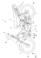
- FIG. 1 is a configuration diagram showing an example of the overall configuration of a motorcycle equipped with an ACG starter (generator motor) according to each embodiment of the present invention.
- FIG. 2 is a developed cross-sectional view of an engine unit corresponding to the AA cross section of FIG. 1. It is an example of sectional drawing of the ACG starter concerning a 1st embodiment. It is a figure which shows an example of a structure of the control relationship of an ACG starter. It is the figure which illustrated the relationship between the coil winding of an ACG starter, and a drive part. It is a figure which shows the drive structure of the general motor by which the three-phase coil was mutually connected. It is a figure which shows an example of the state change of each switching element when a generator motor unit performs power running control.
- FIG. 1 is a configuration diagram showing an example of the overall configuration of a motorcycle 1 on which an ACG starter (generator motor) 60 according to each embodiment of the present invention is mounted.
- the engine unit 2 is mounted at the center in the longitudinal direction of the vehicle body, a seat 3 on which an occupant sits is provided above the rear of the engine unit 2, and a fuel tank 4 is provided below the seat 3.
- a headlamp (lighting device) HL is provided on the front surface of the motorcycle 1.
- the front wheel Wf is rotatably supported by the front fork 5.
- a steering handle 6 is provided on the top of the front fork 5.
- a brake lever (not shown) and a throttle grip (not shown) are arranged on the right side of the steering handle 6. Further, the rear wheel Wr is swingably supported by the vehicle body frame via the swing arm 7.
- FIG. 2 is a developed sectional view of the engine unit 2 corresponding to the AA section of FIG.
- the engine unit 2 includes a reciprocating engine 10 that is an internal combustion engine that outputs a driving force and a multistage transmission 11 as an integrated block.
- the engine 10 and the transmission 11 are configured to be able to transmit power via the centrifugal clutch 8 and the transmission clutch 12.
- the engine 10 has a piston 14 slidably fitted in a cylinder bore of a cylinder block 13. It is connected to a crankshaft (rotation output shaft) 16 via a piston 14 h and a connecting rod 15. As shown in FIG. 1, the engine 10 is mounted on a vehicle in a substantially horizontal posture in which the cylinder block 13 extends forward of the vehicle body with respect to the crankshaft 16.
- crankshaft 16 is rotatably supported via a bearing 18 on a crankcase 17 coupled to the base end of the cylinder block 13.
- a cylinder head 20 that forms a combustion chamber 19 with the piston 14 is attached to the tip of the cylinder block 13.
- reference numeral 21 in FIG. 2 is an ignition device installed in the cylinder head 20 so as to face the combustion chamber 19.
- Reference numeral 22 denotes a valve operating device that is provided on the distal end side of the cylinder head 20 and that opens and closes an intake / exhaust valve (not shown) in conjunction with the crankshaft 16 and is covered with a head cover 20C. 2 are crank webs provided on both sides in the axial direction of a connecting portion (crank pin) with the connecting rod 15 on the crankshaft 16.
- Reference numeral 17 a denotes a crank chamber in the crankcase 17 that accommodates almost the entire region of the crankshaft 16.
- a centrifugal clutch 8 is provided on the outer periphery (the outer periphery outside the crank web 23 in the axial direction) of one end of the crankshaft 16 in the axial direction (the end on the right side in FIG. 2, hereinafter referred to as the right end). Yes.
- the centrifugal clutch 8 rotates integrally with the clutch inner 24 fixed to the right end portion of the crankshaft 16, the clutch outer 25 rotatably supported on the outer periphery of the right end portion of the crankshaft 16, and the clutch inner 24.
- a centrifugal weight 26 for connecting the clutch inner 24 and the clutch outer 25 by centrifugal force.
- the centrifugal clutch 8 outputs the rotational power of the crankshaft 16 to the clutch outer 25 when the rotational speed of the crankshaft 16 reaches a predetermined speed or higher.
- an output gear 28 meshing with an input gear 27 integrated with the transmission clutch 12 is coupled to the clutch outer 25 so as to be integrally rotatable.
- a main shaft 29 and a countershaft 30 of the transmission 11 are provided in parallel to the crankshaft 16 at a position behind the rotation center O of the crankshaft 16 in the crankcase 17.
- the main shaft 29 and the counter shaft 30 are rotatably supported in the crankcase 17 through a pair of bearings arranged separately from each other.
- the main shaft 29 is disposed at a position adjacent to the rear side of the crankshaft 16, and the counter shaft 30 is disposed at a position adjacent to the rear side of the main shaft 29.
- a main transmission gear group M1 is disposed on the main shaft 29 of the transmission 11.
- a counter gear group M2 that meshes with the main gear group M1 is disposed on the counter shaft 30.
- the input gear 27 and the transmission clutch 12 meshed with the output gear 28 on the crankshaft 16 side are disposed at one end portion of the main shaft 29 in the axial direction (the right end portion in FIG. 2, hereinafter referred to as the right end portion). And are provided.
- the input gear 27 is rotatably supported on the outer periphery of the main shaft 29.
- An output sprocket 33 is attached to the other axial end of the counter shaft 30 (the left end in FIG. 2).
- a power transmission chain (not shown) is wound around the output sprocket 33, and the rotation of the countershaft 30 is transmitted to the rear wheel Wr which is a drive wheel via the chain.
- the drive transmission gears of the main gear group M1 and the counter gear group M2 are selected by a turning operation of a shift drum (not shown) provided in the crankcase 17, and thereby any transmission gear stage including neutral is selected. (Gear position) is set.
- the transmission clutch 12 includes a clutch outer 35, a clutch inner 36, a plurality of driving friction plates 37, a plurality of driven friction plates 38, a clutch spring (not shown), and an operation plate 40.
- the clutch outer 35 has a bottomed cylindrical shape that is rotatably supported on the main shaft 29 in a state of being integrally coupled to the input gear 27.
- the clutch inner 36 has a substantially disk shape that is spline-fitted to the main shaft 29.
- the plurality of drive friction plates 37 are locked to the clutch outer 35 so as to be integrally rotatable.
- the plurality of driven friction plates 38 are engaged with the clutch inner 36 so as to be integrally rotatable, and are in frictional contact with the drive friction plate 37.
- the clutch spring urges the driving friction plate 37 and the driven friction plate 38 in the press-contact direction.
- the operation panel 40 releases the urging force of the clutch spring acting between the driving friction plate 37 and the driven friction plate 38.
- the driving friction plate 37 on the clutch outer 35 side and the driven friction plate 38 on the clutch inner 36 side are alternately arranged in the axial direction, and are pressed against each other under the urging force of the clutch spring. Thereby, power transmission between the clutch outer 35 and the clutch inner 36 becomes possible. Further, when the operation plate 40 releases the urging force of the clutch spring, power transmission between the clutch outer 35 and the clutch inner 36 is interrupted.
- the operation plate 40 is configured to be movable back and forth in the axial direction in conjunction with an operation of a shift pedal (not shown).
- the shift pedal When the shift pedal is operated, the operation plate 40 releases the urging force of the clutch spring acting between the drive friction plate 37 and the driven friction plate 38 for a predetermined period before the transmission gear meshes, thereby Power transmission between the outer 35 and the clutch inner 36 is cut off. Then, after the transmission gear is engaged, the drive friction plate 37 and the driven friction plate 38 are engaged.
- a kick spindle 42 of the kick starter 41 is rotatably attached to the lower rear side of the crankcase 17.
- the kick spindle 42 transmits the rotation to the crankshaft 16 only when the kick pedal 43 is depressed.
- the other end portion in the axial direction of the crankshaft 16 (the left end portion in FIG. 2, hereinafter referred to as the left end portion) is a circular opening 17b formed in the side wall (wall portion) of the crankcase 17. And protrudes outward from the side wall of the crankcase 17.
- an ACG starter 60 serving as both an AC generator and a starter motor for the engine 10 is attached.
- the left end portion of the crankshaft 16 is covered with a concave engine cover 51 attached to the side wall of the crankcase 17 by bolt fastening or the like.
- the engine cover 51 includes a bottom wall portion 51a and a side wall portion 51b (cover portion).
- the bottom wall portion 51a covers the left end portion of the crankshaft 16 from the left side.
- the side wall portion 51 b extends so as to rise from the outer peripheral edge of the bottom wall portion 51 a, abuts against the side wall of the crankcase 17 at the tip, and is coupled to the crankcase 17.
- FIG. 3 is an example of a cross-sectional view of the ACG starter 60 according to the first embodiment.
- the ACG starter 60 includes a rotor (rotor) 61 that rotates integrally with the crankshaft 16 and a stator (stator) 65.
- the rotor (rotor) 61 has a magnet.
- the rotor 61 has a substantially cylindrical shape.
- the bottom wall portion 61A forms a disk surface, and the opposite side of the bottom wall portion 61A opens to introduce the crankshaft 16.
- a magnet 62 is attached or formed on the inner peripheral surface 61B of the side wall portion of the rotor 61.
- the first stator 65 is connected to, for example, the crankcase 17 and accommodated inside in the radial direction of the rotor 61.
- the first stator 65 includes a plurality of externally toothed stator cores 66 protruding in the direction of the rotor 61 and wound with a coil.
- the stator core 66 causes the rotor 61 to generate torque by causing a magnetic flux generated by energizing the coil to act on the magnet 62.
- the first stator 65 takes out the induced current generated by the rotation of the rotor 61 accompanying the traveling of the motorcycle 1 and generates electric power.
- the electric power generated by the first stator 65 is stored in a battery 80 (described later).
- the first stator 65 has a structure in which, for example, 18 stator cores 66 are provided, and the U pole, the V pole, and the W pole are sequentially arranged one by one.
- a total of about 12 magnets 62 having an S pole on the side facing the stator core 66 and an N pole are alternately provided.
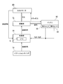
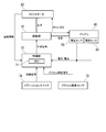
- FIG. 4 is a diagram illustrating an example of a control-related configuration of the ACG starter 60.
- the ACG starter 60 is controlled by a control unit 70 (drive control unit) and a drive unit 72 (drive control unit).
- the control unit 70 is a microcomputer centering on a CPU (Central Processing Unit) 71, for example.
- the control unit 70 acquires rotation information from the Hall IC (not shown) of the ACG starter 60. Instead of the rotation information of the ACG starter 60, the rotation angle information of the crankshaft 16 or the like may be acquired from a crank angle sensor or a control device of the engine 10.
- the control unit 70 calculates the rotation speed N of the rotor 61 based on the rotation information of the ACG starter 60.
- the driving unit 72 includes, for example, a plurality of switching elements for controlling the ACG starter 60 in three phases of U phase, V phase, and W phase (described later).
- the plurality of switching elements have a bridge circuit that sandwiches a coil therebetween.
- the control unit 70 drives the ACG starter 60 according to a start signal input from the ignition switch 74 (power running), and causes the ACG starter 60 to output a torque for starting the engine 10. This start signal may be input from the control device of the engine 10.
- the power running control of the ACG starter 60 may be performed in order to output an assist torque when the motorcycle 1 starts.
- the ACG starter 60 is caused to generate electric power (regeneration) using the output of the engine 10 according to the charging state of the battery 80 to charge the battery 80.
- the control unit 70 generates a control signal for switching element groups (UTr1 to UTr5, VTr1 to VTr5, and WTr1 to WTr5; described later) for performing the phase regulation control, and outputs the control signal to the driving unit 72.
- Information on the voltage between terminals of the battery 80 and / or the amount of charge / discharge current is input to the control unit 70 from the voltage sensor 82 and the current sensor 84 attached to the battery 80.
- the control unit 70 estimates the charge state (charge rate) of the battery 80 based on the voltage between the terminals of the battery 80, or calculates the charge state (charge rate) of the battery 80 by integrating the charge / discharge current amount. .
- the battery 80 supplies power for driving the ACG starter 60 and power for operating other electrical components (such as a headlamp).
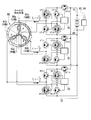
- FIG. 5 is a diagram illustrating the relationship between the coil winding of the ACG starter 60 and the drive unit 72.
- the three-phase coils formed by the U pole 66a, the V pole 66b, and the W pole 66c are not connected to each other, and each phase is a U-phase switching element (UTr1-UTr5).
- the energization is controlled by the V-phase switching elements (VTr1-VTr5) and the W-phase switching elements (WTr1-WTr5). With such a structure, it is possible to output a larger torque than that in which coils of each phase are connected.
- the magnet 62 includes an N pole 62 a that is an N pole on the side facing the stator core 66, and an S pole 62 b that is an S pole.
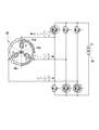
- FIG. 6 is a diagram showing a general motor drive structure in which three-phase coils are connected to each other.
- the current Iq contributing to the torque is the sum of the components orthogonal to the magnetic flux direction of the rotor 61. Therefore, when the impedance of each phase is Z and the battery voltage is Vb, the following equation (1) is established.
- the motor shown in FIG. 6 can output a torque Tq proportional to the current Iq.
- FIG. 7 is a diagram illustrating an example of a state change of each switching element when the generator-motor unit performs power running control.
- the control unit 70 is mounted on the motorcycle 1 when, for example, only the U phase is used for power generation.
- the V-phase and the W-phase are not in a state where power generation is not performed.
- the friction can be reduced as compared with the case where all three phases are used for power generation.
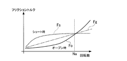
- the generator motor unit is either in a state where no power generation is performed, either in a state where both ends of the coil are released (open state) or in a state where both ends of the coil are short-circuited (short state). Can be selected. Even when power generation is not performed, a certain amount of friction torque is generated, but this friction torque has a characteristic that changes according to the rotational speed of the rotor 61.
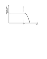
- FIG. 8 is a diagram showing the characteristics of the friction torque according to the rotational speed of the rotor 61.
- the friction torque Fs in the short state becomes larger than the friction torque Fo in the open state, and the rotor It is known that the friction torque Fs in the short state is smaller than the friction torque Fo in the open state in the high rotation range where the rotation speed N of 61 is equal to or greater than the ideal threshold value Na.
- the ideal threshold value Na is a conforming value determined based on the size of the ACG motor 60, the number of turns of the coil, the number of poles, and the like.
- the control unit 70 of the present embodiment opens the V-phase and W-phase coils, and the rotational speed N of the rotor 61 is in the high rotational speed range.
- the V-phase and W-phase coils are short-circuited.
- the friction can be further reduced as compared with the case where the entire rotation region is maintained in either the open state or the short state.
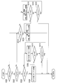
- FIG. 9 is an example of a flowchart showing a flow of processing executed by the control unit 70 of the first embodiment. The process of the flowchart of FIG. 9 is repeatedly executed from when the engine 10 is started until it stops.
- the control unit 70 determines whether or not the rotational speed N of the rotor 61 is less than a first threshold value N1 (predetermined rotational speed) (step S100). When the rotational speed N of the rotor 61 is less than the first threshold value N1, the control unit 70 operates the U-phase coil as a phase regulator to extract the generated power and opens the V-phase and W-phase coils. (Step S102), one routine of the process of the flowchart of FIG. 9 ends.
- a first threshold value N1 predetermined rotational speed
- the control unit 70 When the rotational speed N of the rotor 61 is equal to or higher than the first threshold value N1, the control unit 70 operates the U-phase coil as a phase regulator and sets the V-phase and W-phase coils in a short state (step S104). Then, the control unit 70 maintains the V-phase and W-phase coils in a short state until the rotational speed N of the rotor 61 becomes less than the second threshold value N2 (step S106).
- N1> N2 is established between the first threshold value N1 and the second threshold value N2.
- the threshold value N1 and the threshold value N2 are values in the vicinity of the ideal threshold value Na described above. As a result, it is possible to prevent the occurrence of hunting in which the state is frequently switched, and to suppress fluctuations in friction.
- control unit 70 operates the U-phase coil as a phase regulator and opens the V-phase and W-phase coils (step S102).
- One routine of the process of the flowchart of FIG. 9 is completed.
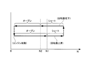
- FIG. 10 is a diagram showing state transitions of the V phase and the W phase realized by the above control.
- the rotational speed N of the rotor 61 is close to zero, and the V-phase and W-phase coils are open. From this point, when the rotational speed N of the rotor 61 increases and becomes equal to or greater than the threshold value N1, the V-phase and W-phase coils are changed to the short state. Thereafter, when the rotational speed N of the rotor 61 decreases and becomes less than the threshold value N2 smaller than the threshold value N1, the V-phase and W-phase coils are changed to the open state.
- FIG. 11 is a diagram illustrating an example of a state change of each switching element when the V-phase and W-phase coils are in an open state.
- the U phase that generates power operates as a phase regulator. That is, the phase of the energization pattern based on the magnetic pole position is varied according to the voltage.
- all the switching elements VTr1 to VTr5, WTr1 to WTr5 are maintained in the OFF state.
- FIG. 12 is a diagram illustrating an example of a state change of each switching element when the V-phase and W-phase coils are short-circuited.
- the U phase that generates power is controlled to operate as a phase regulator.
- the switching elements VTr2, VTr4, WTr2, and WTr4 are turned on, and both ends of the coils of each phase are kept short-circuited. That is, for the V phase and the W phase that do not generate power, among the switching elements, the switching element on the cathode side of the battery connected to the (electric generator unit) is turned on, and the switching element on the anode side is turned off.
- the switching elements VTr1, VTr3, WTr1, and WTr3 may be turned on.
- the three-phase coils are not connected to each other in the ACG starter 60, and each phase is energized and controlled by a dedicated switching element group. The Therefore, it is possible to output a larger torque than that in which the coils of each phase are connected.
- the control unit 70 uses, for example, only the U phase for power generation, and does not generate power for the V phase and the W phase. Therefore, friction can be reduced compared to the case where all three phases are used for power generation. As a result, it is possible to improve the torque output performance while suppressing the increase in friction while avoiding the enlargement of the ACG starter 60.
- the generator motor unit of the present embodiment selects either a state where both ends of the coil are released (open state) or a state where both ends of the coil are short-circuited (short state) as “a state where power generation is not performed”. can do. Then, when the rotational speed N of the rotor 61 is in the low rotational speed range, the control unit 70 of the present embodiment opens the V-phase and W-phase coils, and the rotational speed N of the rotor 61 is in the high rotational speed range. In this case, the V-phase and W-phase coils are short-circuited. Therefore, the friction can be further reduced as compared with the case where the entire rotation range is maintained in either the open state or the short state.
- the control unit 70 estimates or calculates the charging rate of the battery 80 based on voltage or current information input from the battery 80, and performs control during regenerative control based on the charging rate of the battery 80.
- FIG. 13 is an example of a flowchart showing a flow of processing executed by the control unit 70 of the second embodiment. The process of the flowchart of FIG. 13 is repeatedly executed from when the engine 10 is started until it stops.
- the control unit 70 determines whether or not the charging rate P indicating the charging state of the battery 80 is equal to or higher than a threshold value (predetermined level) P1 (for example, about 50%) (step S200).
- a threshold value for example, about 50%
- the charging rate P of the battery 80 and the voltage between the terminals of the battery 80 have a certain degree of correlation. Therefore, the determination in step S200 may compare the voltage between the terminals of the battery 80 with a threshold value. The same applies hereinafter.
- the control unit 70 determines whether or not the rotational speed N of the rotor 61 is less than the first threshold value N1 (step S202). When the rotational speed N of the rotor 61 is less than the first threshold value N1 in step S202, the control unit 70 operates the U-phase coil as a phase regulator and opens the V-phase and W-phase coils (step S204). ), One routine of the process of the flowchart of FIG.
- step S202 when the rotational speed N of the rotor 61 is equal to or higher than the first threshold value N1 in step S202, the control unit 70 operates the U-phase coil as a phase regulator and puts the V-phase and W-phase coils into a short state. (Step S206). Then, the control unit 70 maintains the V-phase and W-phase coils in a short state until the rotational speed N of the rotor 61 becomes less than the second threshold value N2 (step S208). However, when the charging rate P of the battery 80 is less than the threshold value P1, the control unit 70 proceeds to step S212 (step S210).
- N1> N2 is established between the first threshold value N1 and the second threshold value N2.
- the threshold value N1 and the threshold value N2 are values in the vicinity of the ideal threshold value Na described above. As a result, it is possible to prevent the occurrence of hunting in which the state is frequently switched, and to suppress fluctuations in friction.
- step S208 when the rotational speed N of the rotor 61 becomes less than the second threshold value N2 in step S208, the control unit 70 operates the U-phase coil as a phase regulator and opens the V-phase and W-phase coils (step S208).
- step S204 one routine of the process of the flowchart of FIG.
- the control unit 70 operates two or more coils as a phase regulator to generate power (step S212).
- the control unit 70 may operate two phase coils of the U phase, the V phase, and the W phase as a phase regulator, or may operate all the phase coils as a phase regulator.
- the coil in the phase that is not operated as the phase regulator may be switched between the open state and the short state according to the rotational speed of the rotor 61 as in steps S202 to S208.
- control unit 70 uses the rotational force of the engine 10 (internal combustion engine) as a part of the coils of the plurality of phases when the state of charge of the in-vehicle battery 80 is not less than a predetermined level.
- the battery 80 is charged with the generated power and the other part of the coils of the plurality of phases is in an open state or a short state, and the charge state of the battery 80 is less than a predetermined level, the battery 80
- the electric power is generated by using the rotational force of the engine 10 (internal combustion engine) in more phases than the partial phase when the state of charge is equal to or higher than a predetermined level.
- the generator motor unit according to the second embodiment can flexibly increase the power generation amount of the ACG starter 60 when the charge rate of the battery 80 is low, and can quickly charge the battery 80. As a result, it is possible to reduce the possibility that the battery 80 will run out.
- the power generation amount can be flexibly generated when the charging rate of the battery 80 is low, in addition to the same effects as the first embodiment.
- the battery 80 can be charged quickly.
- FIG. 14 is a diagram illustrating an example of a control-related configuration of the ACG starter 60 according to the third embodiment.
- an accelerator opening signal indicating the accelerator opening AC is input to the controller 70 from the accelerator opening sensor 76.
- the accelerator opening sensor 76 detects, as the accelerator opening AC, for example, a rotation amount of a rotating shaft that extends from a throttle grip to which an acceleration instruction from the driver is input and is rotated by a throttle wire.
- the control unit 70 includes information indicating an acceleration instruction to the motorcycle 1, such as the accelerator opening AC input from the accelerator opening sensor 76, and the charging rate of the battery 80 (see the second embodiment). Based on the above, the control during the regenerative control is dynamically changed.
- FIG. 15 is an example of a flowchart showing a flow of processing executed by the control unit 70 of the third embodiment. The process of the flowchart of FIG. 15 is repeatedly executed from when the engine 10 is started until it stops.
- control unit 70 determines whether or not the accelerator opening degree AC input from the accelerator opening degree sensor 76 is equal to or greater than a threshold value A1 (for example, about 50 [%]) (step S300). In this determination, information such as the vehicle speed and acceleration may be taken into account in addition to the accelerator opening.
- a threshold value A1 for example, about 50 [%]
- the control unit 70 determines that the charging rate P indicating the charging state of the battery 80 is a threshold value (predetermined degree) P1 (for example, 50 It is determined whether or not it is about [%] (step S302).
- step S304 the control unit 70 determines whether or not the rotational speed N of the rotor 61 is less than the first threshold value N1 (step S304).
- the control unit 70 opens all the phase coils (step S306), and ends one routine of the process of the flowchart of FIG. To do.
- step S304 when the rotational speed N of the rotor 61 is equal to or greater than the first threshold value N1 in step S304, the control unit 70 short-circuits all the phase coils (step S308). Then, the control unit 70 maintains the V-phase and W-phase coils in a short state until the rotational speed N of the rotor 61 becomes less than the second threshold value N2 (step S310). However, when the accelerator opening degree AC is less than the threshold value A1, the control unit 70 ends one routine of the process of the flowchart of FIG. 15 (step S312).
- N1> N2 is established between the first threshold value N1 and the second threshold value N2. This can prevent hunting from occurring. Further, when the rotational speed N of the rotor 61 becomes less than the second threshold value N2 in step S310, the control unit 70 opens all the phase coils (step S306), and executes one routine of the process of the flowchart of FIG. finish.
- step S314 when the accelerator opening degree AC input from the accelerator opening degree sensor 76 is less than the threshold value A1 in step S300, or when the charging rate P of the battery 80 is less than the threshold value P1 in step S302, the control unit 70 Then, it is determined whether or not the rotational speed N of the rotor 61 is less than the first threshold value N1 (step S314).
- control unit 70 When the rotational speed N of the rotor 61 is less than the first threshold value N1 in step S314, the control unit 70 operates the U-phase coil as a phase regulator and opens the V-phase and W-phase coils (step S316). ), One routine of the process of the flowchart of FIG.
- control unit 70 operates the U-phase coil as a phase regulator and puts the V-phase and W-phase coils into a short state. (Step S318).
- the control unit 70 maintains the V-phase and W-phase coils in a short state until the rotational speed N of the rotor 61 becomes less than the second threshold value N2 (step S320). However, when the accelerator opening degree AC is equal to or greater than the threshold value A1, the control unit 70 ends one routine of the process of the flowchart of FIG. 15 (step S322).
- N1> N2 is established between the first threshold value N1 and the second threshold value N2. This can prevent hunting from occurring.
- step S320 when the rotational speed N of the rotor 61 is less than the second threshold value N2 in step S320, the control unit 70 operates the U-phase coil as a phase regulator and opens the V-phase and W-phase coils (step S320).
- step S316 one routine of the process of the flowchart of FIG.
- the control unit 70 sets all of the coils of the plurality of phases to an open state or a short state when the charge state of the in-vehicle battery 80 is greater than or equal to a predetermined level.
- a part of the coils of the plurality of phases is generated using the rotational force of the engine 10 (internal combustion engine), and the battery 80 is charged with the generated power.
- another part of the plurality of phase coils is set in an open state or a short state.
- the generator-motor unit according to the third embodiment is configured such that when the driver gives an instruction to accelerate the motorcycle 1 and the battery 80 has a sufficient charge rate, all the phase coils are opened or Short circuit. Therefore, the friction can be further reduced and the acceleration performance of the motorcycle 1 can be improved.
- the same effects as in the first embodiment can be obtained, the friction is further reduced, and the acceleration performance of the motorcycle 1 is improved. be able to.
- the generator-motor unit according to the third embodiment may also perform the processing described in the second embodiment. That is, the control unit 70 (1) when the accelerator opening degree AC is equal to or larger than the threshold value and the charging rate P of the battery 80 is equal to or larger than the threshold value P1, the coils of all phases are set to the open state or the short state, and (2 ) When the accelerator opening degree AC is less than the threshold value and the charging rate P of the battery 80 is greater than or equal to the threshold value P1, only the U-phase coil is operated as a phase regulator, and (3) the battery 80 regardless of the accelerator opening degree AC. When the charging rate P is less than the threshold value P1, two or more phase coils may be operated as a phase regulator.
- FIG. 16 is a diagram illustrating an example of a control-related configuration of the ACG starter 60 according to the fourth embodiment.
- an accelerator opening signal indicating the accelerator opening AC is input to the control unit 70 from the accelerator opening sensor 76.
- a vehicle speed signal indicating the vehicle speed V is input to the control unit 70 from the vehicle speed sensor 78.
- a crank angle signal indicating the crank angle ⁇ is input to the control unit 70 from the crank angle sensor 79.
- the vehicle speed sensor 78 is attached to the wheels, the transmission 11, the crankshaft 16, and the like, and detects the vehicle speed of the motorcycle.
- the crank angle sensor 79 detects the rotation angle of the crankshaft 16.
- the control unit 70 performs acceleration assist control at the start based on the accelerator opening degree AC input from the accelerator opening degree sensor 76 and the vehicle speed V input from the vehicle speed sensor 78.
- FIG. 17 is an example of a flowchart showing a flow of processing executed by the control unit 70 of the fourth embodiment. The process of the flowchart of FIG. 17 is repeatedly executed from when the engine 10 is started until it stops.
- the control unit 70 determines whether or not the vehicle speed V input from the vehicle speed sensor 78 is less than a threshold value V1 (a positive value near zero), that is, whether or not the motorcycle 1 is in a stopped state ( Step S400).
- a threshold value V1 a positive value near zero
- the control unit 70 ends one routine of the process of the flowchart of FIG. Instead of the determination in step S400, it may be determined whether or not the rotational speed N of the rotor 61 is less than a threshold value N3 (a positive value near zero). In this case, the vehicle speed sensor 78 is not an essential configuration.
- Step S402 when the vehicle speed V is less than the threshold value V1 in step 400, the control unit 70 causes the accelerator opening degree AC to be equal to or greater than the threshold value A2 (for example, about 5%) (start acceleration instruction is given by the driver).
- control unit 70 determines whether or not charging rate P of battery 80 is equal to or greater than threshold value P1 (for example, about 50%) (step S404).
- the control unit 70 ends one routine of the process of the flowchart of FIG. Note that the determination in step S404 may be omitted, and the process may proceed to step S406 when the accelerator opening degree AC is equal to or greater than the threshold value A2.
- the control unit 70 determines whether or not the rotational speed Ne of the engine 10 is greater than or equal to the threshold value (predetermined rotational speed) Ne1 (step S406). ).
- the rotational speed Ne of the engine 10 is calculated based on, for example, the crank angle ⁇ .
- the control unit 70 at least among the U-phase, V-phase, and W-phase coils until the rotational speed Ne of the engine 10 becomes equal to or higher than the threshold value Ne1.
- a part is subjected to power running control and the assist torque is output to the ACG starter 60 (step S408).
- the threshold value Ne1 corresponds to a “predetermined speed” when the centrifugal clutch 8 outputs the rotational power of the crankshaft 16 to the clutch outer 25 when the rotational speed of the crankshaft 16 reaches or exceeds a predetermined speed. This is the rotational speed of the engine 10. Instead of the determination regarding the rotation speed of the engine 10, a determination regarding the rotation speed of the rotor 61 may be performed. *
- FIG. 18 is a diagram illustrating the relationship between the change in the rotational speed Ne of the engine 10 and the strength of the assist torque output from the ACG starter 60.
- control unit 70 determines whether the engine 10 (internal combustion engine) has a plurality of phases until the rotation speed of the engine 10 (internal combustion engine) becomes equal to or higher than a predetermined rotation speed after the vehicle is instructed to be accelerated or stopped at low speed.
- the power running control of the ACG starter 60 generator motor is performed as a first state in which at least a part of the coil generates torque in the rotor 60.
- the generator-motor unit according to the fourth embodiment has a sufficient charge rate of the battery 80 when the start instruction is given by the driver when the motorcycle 1 is in a very low speed state such as a stopped state or slow running. Then, power running control is performed on at least one phase coil to output assist torque. Therefore, the time until the centrifugal clutch connects the crankshaft 18 and the clutch outer 25 can be shortened, and the acceleration performance when the motorcycle 1 starts can be improved.
- the acceleration performance at the start of the motorcycle 1 can be improved in addition to the same effects as the first embodiment. .
- FIG. 19 is a diagram illustrating a wiring structure around the ACG starter 60 of the generator-motor unit according to the fifth embodiment.
- the generator-motor unit according to the fifth embodiment generates, for example, a voltage (for example, a voltage slightly higher than 12V) for charging the battery 80 by the U-phase coil after the engine 10 is started, and the V-phase coil. Generates a voltage (for example, 24 V) for driving the headlamp HL, and the W-phase coil is opened or shorted as in the first embodiment.
- the V-phase coil can generate a voltage different from that of the U-phase by, for example, making the number of turns and switching timing different from those of the U-phase coil. In FIG. 19, the W-phase switching element is not shown.
- a bypass capacitor C, a resistor R, and an LED (Light Emitting Diode) that is a light emitter of the headlamp HL are connected between, for example, V-phase output terminals of the drive unit according to the fifth embodiment.
- the generator-motor unit of the fifth embodiment includes a plurality of coils that are not connected to each other. Therefore, a plurality of voltages can be generated without adding a boost converter or the like. As a result, the cost and weight of the apparatus can be reduced.
- the same effect as that of the first embodiment can be obtained, and a plurality of voltages can be generated without adding a boost converter or the like. it can. As a result, the cost and weight of the apparatus can be reduced.
- the ACG starter 60 is controlled by three phases, but may be controlled by two phases, four phases, five phases, six phases, or more.
- the generator-motor unit of the present invention can be mounted not only on motorcycles but also on all kinds of vehicles such as ordinary cars and large cars.
- the generator-motor unit of the present invention can also be used for purposes other than being mounted on a vehicle.
Landscapes
- Engineering & Computer Science (AREA)
- Chemical & Material Sciences (AREA)
- Combustion & Propulsion (AREA)
- Mechanical Engineering (AREA)
- General Engineering & Computer Science (AREA)
- Power Engineering (AREA)
- Transportation (AREA)
- Control Of Eletrric Generators (AREA)
- Permanent Magnet Type Synchronous Machine (AREA)
- Windings For Motors And Generators (AREA)
- Control Of Motors That Do Not Use Commutators (AREA)
- Control Of Vehicle Engines Or Engines For Specific Uses (AREA)
- Electric Propulsion And Braking For Vehicles (AREA)
Abstract
Priority Applications (6)
| Application Number | Priority Date | Filing Date | Title |
|---|---|---|---|
| CN201380074802.0A CN105052034B (zh) | 2013-03-21 | 2013-12-11 | 发电电动单元、以及发电电动机的控制方法 |
| JP2015506554A JP6038285B2 (ja) | 2013-03-21 | 2013-12-11 | 発電電動ユニット、および発電電動機の制御方法 |
| EP13878969.8A EP2978124B1 (fr) | 2013-03-21 | 2013-12-11 | Unité de génération de puissance, et procédé de commande de moteur-générateur |
| US14/777,650 US9709015B2 (en) | 2013-03-21 | 2013-12-11 | Power generation unit, and motor generator control method |
| BR112015023575A BR112015023575A8 (pt) | 2013-03-21 | 2013-12-11 | unidade de geração de potência e método para controlar motor gerador". |
| PH12015502179A PH12015502179A1 (en) | 2013-03-21 | 2015-09-17 | Power generation unit, and motor genrator control method |
Applications Claiming Priority (2)
| Application Number | Priority Date | Filing Date | Title |
|---|---|---|---|
| JP2013058438 | 2013-03-21 | ||
| JP2013-058438 | 2013-03-21 |
Publications (1)
| Publication Number | Publication Date |
|---|---|
| WO2014147904A1 true WO2014147904A1 (fr) | 2014-09-25 |
Family
ID=51579615
Family Applications (1)
| Application Number | Title | Priority Date | Filing Date |
|---|---|---|---|
| PCT/JP2013/083254 Ceased WO2014147904A1 (fr) | 2013-03-21 | 2013-12-11 | Unité de génération de puissance, et procédé de commande de moteur-générateur |
Country Status (8)
| Country | Link |
|---|---|
| US (1) | US9709015B2 (fr) |
| EP (1) | EP2978124B1 (fr) |
| JP (1) | JP6038285B2 (fr) |
| CN (1) | CN105052034B (fr) |
| BR (1) | BR112015023575A8 (fr) |
| MY (1) | MY172508A (fr) |
| PH (1) | PH12015502179A1 (fr) |
| WO (1) | WO2014147904A1 (fr) |
Cited By (2)
| Publication number | Priority date | Publication date | Assignee | Title |
|---|---|---|---|---|
| JP2021175299A (ja) * | 2020-04-27 | 2021-11-01 | 力也 阿部 | 耐圧低減回路、回転機、および、インバータ電源装置 |
| WO2025013902A1 (fr) | 2023-07-11 | 2025-01-16 | 富士フイルム株式会社 | Composition, film optiquement anisotrope et composé |
Families Citing this family (9)
| Publication number | Priority date | Publication date | Assignee | Title |
|---|---|---|---|---|
| CN105102791B (zh) * | 2013-04-01 | 2016-12-21 | 丰田自动车株式会社 | 充电控制装置、车辆控制装置、车辆、充电控制方法以及车辆控制方法 |
| JP6571548B2 (ja) * | 2016-01-22 | 2019-09-04 | 株式会社シマノ | 釣り用リール |
| CN106301123B (zh) * | 2016-10-20 | 2021-03-23 | 重庆乔麦科技有限公司 | 一种电动机发电电路 |
| CN106762313B (zh) * | 2017-02-08 | 2018-09-11 | 重庆望江摩托车制造有限公司 | 一种磁电机控制系统以及混合动力系统 |
| JP6568158B2 (ja) * | 2017-07-28 | 2019-08-28 | 株式会社Subaru | 車両用制御装置 |
| WO2019049447A1 (fr) * | 2017-09-08 | 2019-03-14 | 本田技研工業株式会社 | Moteur à combustion interne |
| CN112406570A (zh) * | 2019-08-22 | 2021-02-26 | 丰疆智能(深圳)有限公司 | 便携式车载补电装置、移动补电设备及其应用 |
| US12409742B2 (en) * | 2022-12-08 | 2025-09-09 | Honda Motor Co., Ltd. | Electric vehicle |
| CN120575977B (zh) * | 2025-08-01 | 2025-11-25 | 泰州市凯华柴油发电机组有限公司 | 一种高效柴油发电机组 |
Citations (6)
| Publication number | Priority date | Publication date | Assignee | Title |
|---|---|---|---|---|
| JP2001211693A (ja) * | 2000-01-24 | 2001-08-03 | Yanmar Diesel Engine Co Ltd | 発電装置 |
| JP4410680B2 (ja) | 2002-10-04 | 2010-02-03 | 株式会社ミツバ | 始動発電システム及び始動発電機 |
| JP2010226926A (ja) * | 2009-03-25 | 2010-10-07 | Honda Motor Co Ltd | 回転電機 |
| JP2011025872A (ja) | 2009-07-28 | 2011-02-10 | Jtekt Corp | 電動パワーステアリング装置 |
| JP2011097739A (ja) * | 2009-10-29 | 2011-05-12 | Mitsubishi Electric Corp | 電源装置 |
| JP2011250557A (ja) * | 2010-05-26 | 2011-12-08 | Seiko Epson Corp | 電気機械装置 |
Family Cites Families (15)
| Publication number | Priority date | Publication date | Assignee | Title |
|---|---|---|---|---|
| GB190311299A (en) * | 1903-05-18 | 1904-05-18 | Ferranti Ltd | Improvements in Alternating Current Motors. |
| US3902073A (en) * | 1974-02-07 | 1975-08-26 | Gen Electric | Starter generator electrical system utilizing phase controlled rectifiers to drive a dynamoelectric machine as a brushless dc motor in the starter mode and to provide frequency conversion for a constant frequency output in the generating mode |
| JP3146743B2 (ja) * | 1993-04-12 | 2001-03-19 | トヨタ自動車株式会社 | リターダ装置 |
| JPH0795789A (ja) * | 1993-09-20 | 1995-04-07 | Nippon Densan Corp | モータ |
| JPH07115704A (ja) * | 1993-10-14 | 1995-05-02 | Toyota Motor Corp | リターダ装置 |
| US5929611A (en) | 1994-09-14 | 1999-07-27 | Coleman Powermate, Inc. | Light weight rotor and stator with multiple coil windings in thermal contact |
| KR100376923B1 (ko) * | 1998-11-18 | 2003-03-26 | 미쓰비시덴키 가부시키가이샤 | 차량용 교류발전기의 제어장치 |
| US20050045392A1 (en) * | 2002-07-31 | 2005-03-03 | Maslov Boris A. | In-wheel electric motors |
| JP4002274B2 (ja) * | 2002-11-11 | 2007-10-31 | 三菱電機株式会社 | 車両用三相交流発電機 |
| US6847147B2 (en) * | 2003-01-29 | 2005-01-25 | Wavecrest Laboratories, Llc | Dynamoelectric machine having windings that differ in wire gauge and number of winding turns |
| WO2005062459A1 (fr) * | 2003-12-18 | 2005-07-07 | Mitsubishi Denki Kabushiki Kaisha | Systeme de commande d'un generateur pour vehicule |
| US7064526B2 (en) * | 2004-04-23 | 2006-06-20 | Astronics Advanced Electronic Systems Corp. | Fault tolerant architecture for permanent magnet starter generator subsystem |
| JP3968785B2 (ja) * | 2004-05-18 | 2007-08-29 | セイコーエプソン株式会社 | 駆動回生制御システム |
| JP4670720B2 (ja) * | 2006-04-21 | 2011-04-13 | 株式会社デンソー | 車両用発電制御装置 |
| JP5990005B2 (ja) * | 2012-02-16 | 2016-09-07 | 富士重工業株式会社 | ハイブリッド車両の電力供給装置 |
-
2013
- 2013-12-11 EP EP13878969.8A patent/EP2978124B1/fr active Active
- 2013-12-11 MY MYPI2015703266A patent/MY172508A/en unknown
- 2013-12-11 US US14/777,650 patent/US9709015B2/en not_active Expired - Fee Related
- 2013-12-11 WO PCT/JP2013/083254 patent/WO2014147904A1/fr not_active Ceased
- 2013-12-11 JP JP2015506554A patent/JP6038285B2/ja not_active Expired - Fee Related
- 2013-12-11 CN CN201380074802.0A patent/CN105052034B/zh not_active Expired - Fee Related
- 2013-12-11 BR BR112015023575A patent/BR112015023575A8/pt not_active Application Discontinuation
-
2015
- 2015-09-17 PH PH12015502179A patent/PH12015502179A1/en unknown
Patent Citations (6)
| Publication number | Priority date | Publication date | Assignee | Title |
|---|---|---|---|---|
| JP2001211693A (ja) * | 2000-01-24 | 2001-08-03 | Yanmar Diesel Engine Co Ltd | 発電装置 |
| JP4410680B2 (ja) | 2002-10-04 | 2010-02-03 | 株式会社ミツバ | 始動発電システム及び始動発電機 |
| JP2010226926A (ja) * | 2009-03-25 | 2010-10-07 | Honda Motor Co Ltd | 回転電機 |
| JP2011025872A (ja) | 2009-07-28 | 2011-02-10 | Jtekt Corp | 電動パワーステアリング装置 |
| JP2011097739A (ja) * | 2009-10-29 | 2011-05-12 | Mitsubishi Electric Corp | 電源装置 |
| JP2011250557A (ja) * | 2010-05-26 | 2011-12-08 | Seiko Epson Corp | 電気機械装置 |
Cited By (4)
| Publication number | Priority date | Publication date | Assignee | Title |
|---|---|---|---|---|
| JP2021175299A (ja) * | 2020-04-27 | 2021-11-01 | 力也 阿部 | 耐圧低減回路、回転機、および、インバータ電源装置 |
| WO2021220537A1 (fr) * | 2020-04-27 | 2021-11-04 | 力也 阿部 | Circuit de réduction de tension de tenue, machine tournante, dispositif d'alimentation électrique à onduleur |
| JP7486712B2 (ja) | 2020-04-27 | 2024-05-20 | 株式会社Dgキャピタルグループ | 耐圧低減回路、回転機、および、インバータ電源装置 |
| WO2025013902A1 (fr) | 2023-07-11 | 2025-01-16 | 富士フイルム株式会社 | Composition, film optiquement anisotrope et composé |
Also Published As
| Publication number | Publication date |
|---|---|
| PH12015502179B1 (en) | 2016-01-25 |
| EP2978124A4 (fr) | 2016-12-21 |
| JP6038285B2 (ja) | 2016-12-07 |
| BR112015023575A2 (pt) | 2017-07-18 |
| CN105052034B (zh) | 2018-06-29 |
| JPWO2014147904A1 (ja) | 2017-02-16 |
| US9709015B2 (en) | 2017-07-18 |
| EP2978124A1 (fr) | 2016-01-27 |
| EP2978124B1 (fr) | 2019-02-06 |
| US20160102644A1 (en) | 2016-04-14 |
| BR112015023575A8 (pt) | 2019-12-03 |
| CN105052034A (zh) | 2015-11-11 |
| PH12015502179A1 (en) | 2016-01-25 |
| MY172508A (en) | 2019-11-28 |
Similar Documents
| Publication | Publication Date | Title |
|---|---|---|
| JP6038285B2 (ja) | 発電電動ユニット、および発電電動機の制御方法 | |
| CN105122612B (zh) | 发电电动单元、动力输出机关、以及车辆 | |
| JP4799619B2 (ja) | 車両用ハイブリッドエンジンアシストシステム | |
| CN106014745B (zh) | 车辆用发动机的起动装置 | |
| JP6802378B2 (ja) | ビークル | |
| WO2016001728A1 (fr) | Système de conduite d'un véhicule | |
| KR102417370B1 (ko) | 마일드 하이브리드 차량의 엔진 시동 장치 및 방법 | |
| JP6207327B2 (ja) | ハイブリッドシステム | |
| JP3846118B2 (ja) | 駆動装置 | |
| WO2020044481A1 (fr) | Véhicule à selle motorisé | |
| JP5515334B2 (ja) | ハイブリッド車両の制御装置 | |
| WO2017126165A1 (fr) | Véhicule équipé d'un moteur | |
| JP5900142B2 (ja) | 車両駆動装置 | |
| JP2013119301A (ja) | ハイブリッド電気自動車のエンジン停止制御装置 | |
| CN110422159A (zh) | 用于内燃机的受控停止的方法和装置 | |
| CN110494646B (zh) | 车辆启动系统 | |
| JP7687065B2 (ja) | 電動車両の制御装置 | |
| JPH09154300A (ja) | 動力伝達装置およびその制御方法 | |
| JP2018118544A (ja) | ハイブリッド車両のエンジン始動制御装置 | |
| JP5155576B2 (ja) | 電気自動車用駆動装置 | |
| JP6120565B2 (ja) | 車両の駆動源の構造 | |
| JP6120564B2 (ja) | 車両の駆動源の構造 |
Legal Events
| Date | Code | Title | Description |
|---|---|---|---|
| WWE | Wipo information: entry into national phase |
Ref document number: 201380074802.0 Country of ref document: CN |
|
| 121 | Ep: the epo has been informed by wipo that ep was designated in this application |
Ref document number: 13878969 Country of ref document: EP Kind code of ref document: A1 |
|
| ENP | Entry into the national phase |
Ref document number: 2015506554 Country of ref document: JP Kind code of ref document: A |
|
| WWE | Wipo information: entry into national phase |
Ref document number: 14777650 Country of ref document: US |
|
| WWE | Wipo information: entry into national phase |
Ref document number: 12015502179 Country of ref document: PH |
|
| NENP | Non-entry into the national phase |
Ref country code: DE |
|
| WWE | Wipo information: entry into national phase |
Ref document number: IDP00201505883 Country of ref document: ID |
|
| WWE | Wipo information: entry into national phase |
Ref document number: 2013878969 Country of ref document: EP |
|
| REG | Reference to national code |
Ref country code: BR Ref legal event code: B01A Ref document number: 112015023575 Country of ref document: BR |
|
| ENP | Entry into the national phase |
Ref document number: 112015023575 Country of ref document: BR Kind code of ref document: A2 Effective date: 20150915 |