WO2014147960A1 - Structure de refroidissement pour composant magnétique, et convertisseur de puissance équipé de cette structure - Google Patents
Structure de refroidissement pour composant magnétique, et convertisseur de puissance équipé de cette structure Download PDFInfo
- Publication number
- WO2014147960A1 WO2014147960A1 PCT/JP2014/000919 JP2014000919W WO2014147960A1 WO 2014147960 A1 WO2014147960 A1 WO 2014147960A1 JP 2014000919 W JP2014000919 W JP 2014000919W WO 2014147960 A1 WO2014147960 A1 WO 2014147960A1
- Authority
- WO
- WIPO (PCT)
- Prior art keywords
- magnetic component
- transformer
- cold air
- case
- housing
- Prior art date
- Legal status (The legal status is an assumption and is not a legal conclusion. Google has not performed a legal analysis and makes no representation as to the accuracy of the status listed.)
- Ceased
Links
Images


Classifications
-
- H—ELECTRICITY
- H01—ELECTRIC ELEMENTS
- H01F—MAGNETS; INDUCTANCES; TRANSFORMERS; SELECTION OF MATERIALS FOR THEIR MAGNETIC PROPERTIES
- H01F27/00—Details of transformers or inductances, in general
- H01F27/08—Cooling; Ventilating
-
- H—ELECTRICITY
- H05—ELECTRIC TECHNIQUES NOT OTHERWISE PROVIDED FOR
- H05K—PRINTED CIRCUITS; CASINGS OR CONSTRUCTIONAL DETAILS OF ELECTRIC APPARATUS; MANUFACTURE OF ASSEMBLAGES OF ELECTRICAL COMPONENTS
- H05K7/00—Constructional details common to different types of electric apparatus
- H05K7/20—Modifications to facilitate cooling, ventilating, or heating
- H05K7/2089—Modifications to facilitate cooling, ventilating, or heating for power electronics, e.g. for inverters for controlling motor
- H05K7/20909—Forced ventilation, e.g. on heat dissipaters coupled to components
-
- H—ELECTRICITY
- H01—ELECTRIC ELEMENTS
- H01F—MAGNETS; INDUCTANCES; TRANSFORMERS; SELECTION OF MATERIALS FOR THEIR MAGNETIC PROPERTIES
- H01F27/00—Details of transformers or inductances, in general
- H01F27/06—Mounting, supporting or suspending transformers, reactors or choke coils not being of the signal type
-
- H—ELECTRICITY
- H01—ELECTRIC ELEMENTS
- H01F—MAGNETS; INDUCTANCES; TRANSFORMERS; SELECTION OF MATERIALS FOR THEIR MAGNETIC PROPERTIES
- H01F27/00—Details of transformers or inductances, in general
- H01F27/08—Cooling; Ventilating
- H01F27/085—Cooling by ambient air
-
- H—ELECTRICITY
- H01—ELECTRIC ELEMENTS
- H01F—MAGNETS; INDUCTANCES; TRANSFORMERS; SELECTION OF MATERIALS FOR THEIR MAGNETIC PROPERTIES
- H01F27/00—Details of transformers or inductances, in general
- H01F27/28—Coils; Windings; Conductive connections
- H01F27/32—Insulating of coils, windings, or parts thereof
- H01F27/324—Insulation between coil and core, between different winding sections, around the coil; Other insulation structures
- H01F27/325—Coil bobbins
-
- H—ELECTRICITY
- H02—GENERATION; CONVERSION OR DISTRIBUTION OF ELECTRIC POWER
- H02M—APPARATUS FOR CONVERSION BETWEEN AC AND AC, BETWEEN AC AND DC, OR BETWEEN DC AND DC, AND FOR USE WITH MAINS OR SIMILAR POWER SUPPLY SYSTEMS; CONVERSION OF DC OR AC INPUT POWER INTO SURGE OUTPUT POWER; CONTROL OR REGULATION THEREOF
- H02M7/00—Conversion of AC power input into DC power output; Conversion of DC power input into AC power output
- H02M7/003—Constructional details, e.g. physical layout, assembly, wiring or busbar connections
Definitions
- the present invention relates to a structure for cooling a magnetic component built in a casing and a power conversion device including the structure.
- a power conversion device such as an AC / DC converter incorporates a magnetic component such as a transformer in a casing and fixes the magnetic component to the bottom of the casing.
- a magnetic component such as a transformer
- it is required to cool the magnetic component efficiently because the magnetic component is a heating element.
- Patent Document 1 As a conventional device for cooling a transformer, for example, one disclosed in Patent Document 1 is known.
- an iron core and a transformer around which a coil is wound are accommodated in a duct, and a blower fan that blows cold air toward the outer periphery of the transformer coil, the transformer, A blower fan that blows cool air toward the rear surface of the fan is provided, and the transformer is cooled by the cool air generated by these blower fans.
- the cold air generated by the blower fan flows while spreading toward the transformer, and the air volume of the cold air contacting the outer periphery of the coil and the back surface of the coil may be reduced.
- the apparatus of patent document 1 requires the exclusive ventilation fan which cools a transformer, there exists a possibility that manufacturing cost may increase.
- transformer becomes large sized, when arrange
- the present invention has been made paying attention to such problems, and while improving the cooling efficiency of the magnetic parts, it is possible to reduce the size and cost of the magnetic parts without problems in terms of the arrangement space with other parts. It aims at providing a cooling structure and a power converter provided with the same.
- a cooling structure for a magnetic component is a structure for cooling a magnetic component built in the housing, and the inside of the housing is enclosed by an internal fan arranged in the housing.
- a cold air passage space through which cool air flows is provided, and a magnetic component placed on the bottom of the housing is fixed with a mounting member at a position facing the suction side of the internal fan in the cold air passage space.
- the generated cool air flow was allowed to pass through the magnetic parts.
- the cooling structure of the magnetic component according to this aspect the flow of rectified cold air generated on the suction side of the internal fan contacts the coil in the magnetic component, so that the heat generated in the coil is dissipated and the magnetic The cooling efficiency of the parts is increased.
- the cooling structure for a magnetic component includes a top plate whose mounting member contacts the top surface of the magnetic component, and a pair of legs that extend downward from the top plate and are fixed to the bottom of the casing. It is a metal plate material provided with the part. According to the cooling structure for a magnetic component according to this aspect, since the attachment member is a simple structure made of a metal plate, the manufacturing cost can be reduced.
- the bottom of the housing on which the magnetic component is placed is a cooling body.
- the heat generated in the magnetic component is directly transferred from the mounting member to the bottom of the casing, which is a cooling body, so that the cooling efficiency of the magnetic component is further increased.
- the power converter device which concerns on 1 aspect of this invention is an apparatus which is provided with the cooling structure of the magnetic component mentioned above, and converts AC power into DC power. According to the power conversion device according to this aspect, it is possible to provide a small and inexpensive power conversion device while improving the cooling efficiency of the magnetic components.
- the cold air generated on the suction side of the internal fan is arranged by placing the magnetic component at a position facing the suction side of the internal fan in the cool air flow path space.
- the rectified cold air generated by the internal fan is brought into contact with the coil in the magnetic component by increasing the air volume, so that the heat generated in the coil is dissipated and the magnetic component is cooled. Efficiency can be increased.
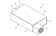
- FIG. 1 It is a perspective view which shows the power converter device provided with the cooling structure of the magnetic component which concerns on 1 aspect of this invention. It is the top view which removed the cover of the power converter and showed the inside. It is the figure which showed the case which comprises a housing
- FIG. 1 shows the power converter 1 of the first embodiment used as an AC / DC converter
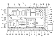
- FIG. 2 shows the inside of the power converter 1 with the lid 10 removed.
- a blower fan 3 is externally attached to one side surface in the longitudinal direction of a rectangular parallelepiped housing 2 constituting the power conversion device 1.
- An input connector 4, a control connector 5, and an output connector 6 are provided in parallel on the other side surface of the casing 2 in the longitudinal direction.
- a power conversion control unit which will be described later, is built in the housing 2.
- the control connector 5 When a control signal is input to the control connector 5, the commercial power input to the input connector 4 is converted from AC to DC by the power conversion control unit. Thus, it is output from the output connector 6 as DC power.
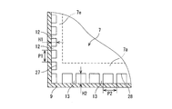
- the housing 2 includes a case 7, a chamber forming wall 8, a housing cover 9, and a lid body 10.
- the case 7 has a bottomed box shape and has a rectangular shape in plan view, a rectangular bottom portion 7a, a pair of short side walls 7b and 7c rising from four sides of the bottom portion 7a, and a pair of long side walls. 7d, 7e.
- the case 7 is formed, for example, by die-casting aluminum having a high thermal conductivity or an aluminum alloy.
- the chamber forming wall 8 is disposed on one side of the case 7 in the longitudinal direction, and faces the abutting wall 8a that abuts one short side wall 7b of the case 7 and the one short side wall 7b of the case 7. It is comprised with the opposing wall 8b.
- the housing cover 9 is provided so as to cover a part of the case 7 and the chamber forming wall 8.
- the lid 10 is provided so as to close the inside of the housing 2 by closing the upper openings of the case 7 and the chamber forming wall 8.
- a plurality of side wall fins 12 extending in the longitudinal direction are formed in one long side wall 7e of the case 7 in a region from the lower end to the upper part on the outer side.
- the plurality of side wall fins 12 are formed in parallel at a predetermined interval in the vertical direction of the long side wall 7e.
- the fin height of each side wall fin 12 is set to H1
- the pitch of the side wall fins 12 is set to P1.
- no side wall fin is formed outside the other long side wall 7 d of the case 7.
- a plurality of bottom fins 13 extending in the longitudinal direction are also formed in the bottom 7a of the case 7 in the region from the left end to the right side of the lower surface thereof.
- the plurality of bottom fins 13 are formed in parallel with a predetermined interval in the short direction of the bottom 7a.
- the fin height of each bottom fin 13 is set to a value H2 (H2> H1) larger than the fin height H1 of the side wall fin 12.
- the pitch of the bottom fins 13 is set to a value P2 (P2> P1) larger than the pitch P1 of the side wall fins 12.
- the housing cover 9 is a cover member that covers the side wall fins 12 and the bottom fins 13 from the outside. As shown in FIGS. 2 and 3, the bottom 7a of the case 7 and the lower openings of the chamber forming wall 8 are formed. A rectangular plate-shaped bottom plate 9a that covers the base plate 9a and a pair of side plates 9b and 9c that rise from the edge of the bottom plate 9a and cover the pair of long side walls 7d and 7e of the case 7 and the side portions of the chamber forming wall 8 are formed. .
- the space between the plurality of side wall fins 12 and the plurality of bottom fins 13 are formed on the outer periphery of the bottom 7a of the case 7 and the one long side wall 7e covered with the housing cover 9 as described above.
- the space between is a plurality of flow paths 27 and 28 extending in the longitudinal direction of the case 7.
- the lid 10 is fixed to the case 7 and the chamber forming wall 8 so as to close the upper openings of the case 7 and the chamber forming wall 8.
- an inner space surrounded by one short side wall 7b of the case 7, the chamber forming wall 8, the housing cover 9, and the lid 10 is defined as a chamber 11 that is a wind tunnel. ing.
- An opening 8c is formed in the facing wall 8b of the chamber forming wall 8 as a blowing inlet.
- the blower fan 3 is mounted at the position of the opening 8c so that the blower port of the blower fan 3 faces the cooling air, and the cooling air generated by the blower fan 3 is fed into the chamber 11. .
- a power conversion control unit and an internal fan 14 are housed inside the case 7.
- the power conversion control unit includes a base substrate 15, an input side noise filter unit 16, a first reactor 17, a second reactor 18, an electric field capacitor group 19, a transformer 20, an output side noise filter unit 21, and a plurality of power conversion control units.
- the semiconductor devices for example, MOS-FETs
- D1 to D12 and the first to third circuit boards 23 to 25 are included.
- the base substrate 15 is a member having a rectangular shape smaller than the planar shape of the bottom 7a of the case 7 and having a notch 15a formed on one long side.
- the base substrate 15 is provided with a predetermined wiring pattern (not shown) for connecting to the input connector 4, the control connector 5 and the output connector 6 described above.
- the base substrate 15 is fixed by bolting on a support base (not shown) formed on the upper surface of the bottom 7a of the case 7 with the notch 15a facing the one long side wall 7e of the case 7. .
- the input side noise filter unit 16 the first reactor 17, the second reactor 18, the electric field capacitor group 19, the output side noise filter unit 21, the semiconductor devices D 1 to D 12, and the first to third circuit substrates 23. 25 are mounted, and the internal fan 14 is also disposed on the base substrate 15.
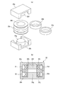
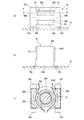
- the transformer 20 is disposed inside the notch 15 a of the base substrate 15, and the transformer 20 is directly fixed to the bottom 7 a of the case 7 by an attachment member 30.
- the transformer 20 includes an upper core 20a, a lower core 20b, a substantially cylindrical bobbin 20c, a primary coil 20d, and a secondary coil 20e.
- the convex portion 20f provided on the upper core 20a and the convex portion 20g provided on the lower core 20b are fitted from above and below into a fitting hole 20h formed along the axis of the bobbin 20c.
- the primary coil 20d is wound around the upper coil housing recess 20i provided at the top of the bobbin 20c
- the secondary coil 20e is wound around the lower coil housing recess 20j provided at the bottom of the bobbin 20c. It is formed.
- the mounting member 30 includes a rectangular top plate 30a that abuts on the upper surface of the upper core 20a of the transformer 20, and two opposite edges of the top plate 30a.
- a pair of leg portions 30b extending downward in parallel with each other and a fixing portion 30c extending in a direction perpendicular to the lower ends of the pair of leg portions 30b.
- a gap S1 is formed between the inner surface of the upper core 20a and the primary coil 20d wound around the upper coil housing recess 20i.
- S1 is a passage space in the transformer through which cold air flows from one opening 30d1 to the other opening 30d2 (hereinafter referred to as a passage space S1 in the transformer). Further, a gap S2 is also formed between the inner surface of the lower core 20b and the secondary coil 20e wound around the lower coil housing recess 20j, and this gap S2 is also formed from one opening 30d1 to the other opening. It is set as the channel space in the transformer through which cold air flows up to 30d2 (hereinafter referred to as channel space S2 in the transformer).
- the semiconductor devices D1 to D6 are mounted at a predetermined interval in the alignment direction along one short side of the base substrate 15.
- the positions of the semiconductor devices D1 to D6 are mounted so as to be in direct contact with one short side wall 7b of the case 7 that defines the chamber 11.
- the other semiconductor devices D7 to D12 are mounted at a predetermined interval in the alignment direction along one long side of the base substrate 15.
- the positions of these semiconductor devices D7 to D12 are mounted so as to directly contact one long side wall 7e of the case 7 forming the side wall fins 12.
- the third circuit board 25 extends and extends in the longitudinal direction at the center position in the short direction of the base substrate 15 and is mounted.
- the second circuit board 24 is mounted on the base board 15 so as to extend in the longitudinal direction at a position close to the other short side wall 7c of the case 7 while standing parallel to the third circuit board 25.
- the input side noise filter unit 16, the first reactor 17, the second reactor 18, and the electric field capacitor group 19 are located between the third circuit board 25 and the other long side wall 7d of the case 7 so as to be positioned between the base board. 15 is implemented.
- the output-side noise filter unit 21 is mounted on the base substrate 15 so as to be positioned between the second circuit board 24 and one long side wall 7e of the case 7.
- the first circuit board 23 extends in the longitudinal direction of the base substrate 15 and is mounted so as to be parallel to the one long side wall 7e at a position close to the one short side wall 7b.
- the internal fan 14 is disposed on the base substrate 15 at a position close to one long side wall 7e between the output side noise filter unit 21 and the transformer 20, and the blowing side 14a faces the output side noise filter unit 21.
- the suction side 14 b is disposed so as to face the transformer 20.
- the transformer 20 is directly fixed to the bottom portion 7a by connecting the fixing portion 30c of the mounting member 30 to the bottom portion 7a of the case 7 via a fixing screw (not shown).
- the control components such as the transformer 20 and the power conversion control unit in the case 7 generate heat, and in particular, the heat generation amount of the primary coil 20d and the secondary coil e of the transformer 20 is large.
- the third circuit board 25 and the second circuit board 24 that stand up and are mounted at the central position in the short direction of the base board 15 function as wind direction plates, as indicated by broken line arrows in FIG.
- a flow of cold air that circulates in the order of the output side noise filter unit 21, the input side noise filter unit 16, the first reactor, the second reactor, the electric field capacitor group 19, and the transformer 20 is generated.
- the suction side 14b of the internal fan 14 sucks ambient air as a rectified flow having a substantially constant flow velocity. For this reason, the flow of the rectified cold air passes through the flow space S1, S2 in the transformer 20 of the transformer 20 facing the suction side 14b of the internal fan 14 with an increased air volume. As described above, the flow of the rectified cold air generated on the suction side 14b of the internal fan 14 flows in the flow passage spaces S1 and S2 of the transformer 20 with increasing air volume. The heat generated in the next coil e is dissipated.
- the cold air blown from the blowout side 14a of the internal fan 14 does not come into contact with the control components having a large heat generation amount, such as the semiconductor devices D7 to D12 and the transformer 20, but comes into contact with the output side noise filter unit 21 with a small heat generation amount. Therefore, the heat generated by other control components (the output side noise filter unit 21, the input side noise filter unit 16, the first reactor, the second reactor, and the electric field capacitor group 19) is also cooled.
- the blower fan 3 is driven, cold air taken from outside is sent into the chamber 11. Since the cold air sent into the chamber 11 enters the plurality of flow paths 28 formed on the bottom 7a side of the case 7 communicating with the chamber 11 and is discharged to the outside, the bottom 7a serves as a cooling body. Further, since the cold air enters the plurality of flow paths 27 formed on the side of one long side wall 7e communicating with the chamber 11 and is discharged to the outside, the one long side wall 7e also serves as a cooling body.
- the cold air flow path space is a flow of cold air circulating in the order of the output side noise filter unit 21, the input side noise filter unit 16, the first reactor, the second reactor, the electric field capacitor group 19, and the transformer 20. It corresponds.
- the flow of the rectified cold air generated on the suction side 14b of the internal fan 14 is increased in the amount of air flowing in the transformer flow path spaces S1, S2 of the transformer 20, so that the primary coil of the transformer 20
- the heat generated in 20d and the secondary coil e is dissipated by the cold air flowing through the in-transformer channel spaces S1 and S2, and the cooling efficiency of the transformer 20 can be sufficiently increased.
- the transformer 20 is fixed so as to be in direct contact with the bottom 7a of the case 7 serving as a cooling body, the heat generated in the transformer 20 is directly transferred from the mounting member 30 to the bottom 7a.
- the cooling efficiency of the transformer 20 can be increased.
- the internal fan 14 blows cold air toward the control component (output-side noise filter unit 21) that generates a small amount of heat, other control components (output-side noise filter unit 21, input-side noise filter unit 16).
- the first reactor, the second reactor, and the electric field capacitor group 19) can be efficiently cooled.
- the mounting member 30 of the present embodiment has a simple structure without mounting a fan on the mounting member 30 that fixes the transformer 20, the manufacturing cost can be reduced, and the arrangement inside the case 7 can be reduced. Sufficient space can be secured.
- the magnetic component is not limited to the transformer 20, but may be a reactor or the like as long as it generates heat.
- the mounting member 30 including the pair of leg portions 30b is shown as an example, but the paired leg portions are further divided, for example, composed of two leg portions, and a total of four pairs.
- the shape may be a leg.
- the magnetic part cooling structure and the power conversion device including the magnetic part cooling structure according to the present invention are small and inexpensive with no problem in terms of arrangement space with other parts while improving the cooling efficiency of the magnetic parts. Useful for making things.
- SYMBOLS 1 Power converter device, 2 ... Housing
Landscapes
- Engineering & Computer Science (AREA)
- Power Engineering (AREA)
- Microelectronics & Electronic Packaging (AREA)
- Physics & Mathematics (AREA)
- Thermal Sciences (AREA)
- Cooling Or The Like Of Electrical Apparatus (AREA)
- Inverter Devices (AREA)
- Dc-Dc Converters (AREA)
- Transformer Cooling (AREA)
Abstract
Priority Applications (4)
| Application Number | Priority Date | Filing Date | Title |
|---|---|---|---|
| JP2015506578A JPWO2014147960A1 (ja) | 2013-03-19 | 2014-02-21 | 磁気部品の冷却構造及びこれを備えた電力変換装置 |
| CN201480007009.3A CN104969313B (zh) | 2013-03-19 | 2014-02-21 | 磁部件的冷却结构和具有该冷却结构的电力转换装置 |
| EP14770981.0A EP2977995A4 (fr) | 2013-03-19 | 2014-02-21 | Structure de refroidissement pour composant magnétique, et convertisseur de puissance équipé de cette structure |
| US14/823,504 US20150348694A1 (en) | 2013-03-19 | 2015-08-11 | Cooling structure for magnetic component and power converter provided therewith |
Applications Claiming Priority (2)
| Application Number | Priority Date | Filing Date | Title |
|---|---|---|---|
| JP2013-056930 | 2013-03-19 | ||
| JP2013056930 | 2013-03-19 |
Related Child Applications (1)
| Application Number | Title | Priority Date | Filing Date |
|---|---|---|---|
| US14/823,504 Continuation US20150348694A1 (en) | 2013-03-19 | 2015-08-11 | Cooling structure for magnetic component and power converter provided therewith |
Publications (1)
| Publication Number | Publication Date |
|---|---|
| WO2014147960A1 true WO2014147960A1 (fr) | 2014-09-25 |
Family
ID=51579663
Family Applications (1)
| Application Number | Title | Priority Date | Filing Date |
|---|---|---|---|
| PCT/JP2014/000919 Ceased WO2014147960A1 (fr) | 2013-03-19 | 2014-02-21 | Structure de refroidissement pour composant magnétique, et convertisseur de puissance équipé de cette structure |
Country Status (5)
| Country | Link |
|---|---|
| US (1) | US20150348694A1 (fr) |
| EP (1) | EP2977995A4 (fr) |
| JP (1) | JPWO2014147960A1 (fr) |
| CN (1) | CN104969313B (fr) |
| WO (1) | WO2014147960A1 (fr) |
Cited By (1)
| Publication number | Priority date | Publication date | Assignee | Title |
|---|---|---|---|---|
| CN109564810A (zh) * | 2016-08-09 | 2019-04-02 | 三菱电机株式会社 | 臭氧发生器用电源装置及臭氧发生装置 |
Families Citing this family (13)
| Publication number | Priority date | Publication date | Assignee | Title |
|---|---|---|---|---|
| US20180006573A1 (en) * | 2015-03-04 | 2018-01-04 | Hitachi, Ltd. | Electrical Power Conversion Unit and Electrical Power Conversion Device |
| US11728087B2 (en) | 2016-05-25 | 2023-08-15 | Delta Electronics (Shanghai) Co., Ltd | Core structure and magnetic device |
| US11901108B2 (en) | 2016-05-25 | 2024-02-13 | Delta Electronics (Shanghai) Co., Ltd. | Power module and power device |
| US20210050142A1 (en) * | 2016-05-25 | 2021-02-18 | Delta Electronics (Shanghai) Co., Ltd. | Power module and power device |
| JP6421898B2 (ja) * | 2016-06-16 | 2018-11-14 | 富士電機株式会社 | 電子機器及び電力変換装置 |
| US10673349B2 (en) * | 2016-12-22 | 2020-06-02 | Hitachi, Ltd. | Power conversion device with efficient cooling structure |
| TWM547216U (zh) * | 2017-04-12 | 2017-08-11 | Chyng Hong Electronic Co Ltd | 高功率密度直流轉交直流功率轉換器之抗流圈模組結構 |
| US9966794B1 (en) * | 2017-08-24 | 2018-05-08 | Zippy Technology Corp. | Power supply for redundant power system |
| US10874036B2 (en) * | 2018-10-08 | 2020-12-22 | Delta Electronics, Inc. | Cabinet and electronic device |
| CN112751473B (zh) * | 2019-10-31 | 2021-11-05 | 台达电子企业管理(上海)有限公司 | 功率模块 |
| CN119049851A (zh) | 2019-10-31 | 2024-11-29 | 台达电子企业管理(上海)有限公司 | 变压器及具有其的功率模块 |
| CN112821722B (zh) | 2019-10-31 | 2022-07-19 | 台达电子企业管理(上海)有限公司 | 功率变换系统 |
| CN114078623A (zh) * | 2020-08-20 | 2022-02-22 | Tdk株式会社 | 线圈部件以及搭载其的开关电源装置 |
Citations (5)
| Publication number | Priority date | Publication date | Assignee | Title |
|---|---|---|---|---|
| JPH0587997U (ja) * | 1992-04-27 | 1993-11-26 | 株式会社ケンウッド | 強制冷却装置 |
| JP2001143938A (ja) * | 1999-11-18 | 2001-05-25 | Tdk Corp | 発熱電子部品の固定放熱構造 |
| JP2007221057A (ja) * | 2006-02-20 | 2007-08-30 | Toyota Industries Corp | 電子機器装置 |
| JP2008187014A (ja) | 2007-01-30 | 2008-08-14 | Mitsubishi Electric Corp | トランスの冷却装置 |
| JP2013157466A (ja) * | 2012-01-30 | 2013-08-15 | Fuji Electric Co Ltd | 電力変換装置 |
Family Cites Families (15)
| Publication number | Priority date | Publication date | Assignee | Title |
|---|---|---|---|---|
| JPS5931798U (ja) * | 1982-08-25 | 1984-02-28 | 株式会社東芝 | 高周波加熱装置 |
| JPS6090817U (ja) * | 1983-11-29 | 1985-06-21 | 東芝オ−デイオ・ビデオエンジニアリング株式会社 | トランス装置 |
| DE8716135U1 (de) * | 1987-12-05 | 1988-02-11 | Ceag Licht- Und Stromversorgungstechnik Gmbh, 4770 Soest | Transformator, Drossel und dgl. |
| JPH0217814U (fr) * | 1988-07-21 | 1990-02-06 | ||
| US5170336A (en) * | 1990-03-05 | 1992-12-08 | Dimensions Unlimited, Inc. | DC to AC inverter with improved forced air cooling method and apparatus |
| CN1026847C (zh) * | 1991-04-05 | 1994-11-30 | 松下电器产业株式会社 | 采用换流器电源的高频加热装置 |
| US5289153A (en) * | 1992-07-01 | 1994-02-22 | General Electric | Snap together, wrap around cored coil clamp |
| US5920249A (en) * | 1997-10-30 | 1999-07-06 | Ford Motor Company | Protective method of support for an electromagnetic apparatus |
| KR100499499B1 (ko) * | 2002-12-26 | 2005-07-05 | 엘지전자 주식회사 | 상업용 전자 레인지 |
| FR2881018B1 (fr) * | 2005-01-19 | 2007-04-06 | Intelligent Electronic Systems | Procede de refroidissement d'un dispositif de conversion statique d'electronique de puissance et dispositif correspondant |
| US8947187B2 (en) * | 2005-06-17 | 2015-02-03 | Grant A. MacLennan | Inductor apparatus and method of manufacture thereof |
| JP2007335518A (ja) * | 2006-06-13 | 2007-12-27 | Toyota Motor Corp | 車両用電気機器の収納容器 |
| JP5042141B2 (ja) * | 2008-06-20 | 2012-10-03 | パナソニック株式会社 | 電子機器 |
| CN201295808Y (zh) * | 2008-11-10 | 2009-08-26 | 华四炜 | 逆变焊机 |
| CN202696480U (zh) * | 2012-06-26 | 2013-01-23 | 深圳古瑞瓦特新能源有限公司 | 逆变器及逆变器散热结构 |
-
2014
- 2014-02-21 CN CN201480007009.3A patent/CN104969313B/zh not_active Expired - Fee Related
- 2014-02-21 EP EP14770981.0A patent/EP2977995A4/fr not_active Withdrawn
- 2014-02-21 JP JP2015506578A patent/JPWO2014147960A1/ja active Pending
- 2014-02-21 WO PCT/JP2014/000919 patent/WO2014147960A1/fr not_active Ceased
-
2015
- 2015-08-11 US US14/823,504 patent/US20150348694A1/en not_active Abandoned
Patent Citations (5)
| Publication number | Priority date | Publication date | Assignee | Title |
|---|---|---|---|---|
| JPH0587997U (ja) * | 1992-04-27 | 1993-11-26 | 株式会社ケンウッド | 強制冷却装置 |
| JP2001143938A (ja) * | 1999-11-18 | 2001-05-25 | Tdk Corp | 発熱電子部品の固定放熱構造 |
| JP2007221057A (ja) * | 2006-02-20 | 2007-08-30 | Toyota Industries Corp | 電子機器装置 |
| JP2008187014A (ja) | 2007-01-30 | 2008-08-14 | Mitsubishi Electric Corp | トランスの冷却装置 |
| JP2013157466A (ja) * | 2012-01-30 | 2013-08-15 | Fuji Electric Co Ltd | 電力変換装置 |
Non-Patent Citations (1)
| Title |
|---|
| See also references of EP2977995A4 |
Cited By (2)
| Publication number | Priority date | Publication date | Assignee | Title |
|---|---|---|---|---|
| CN109564810A (zh) * | 2016-08-09 | 2019-04-02 | 三菱电机株式会社 | 臭氧发生器用电源装置及臭氧发生装置 |
| CN109564810B (zh) * | 2016-08-09 | 2022-06-07 | 三菱电机株式会社 | 臭氧发生器用电源装置及臭氧发生装置 |
Also Published As
| Publication number | Publication date |
|---|---|
| US20150348694A1 (en) | 2015-12-03 |
| JPWO2014147960A1 (ja) | 2017-02-16 |
| EP2977995A4 (fr) | 2016-11-16 |
| CN104969313B (zh) | 2017-03-08 |
| CN104969313A (zh) | 2015-10-07 |
| EP2977995A1 (fr) | 2016-01-27 |
Similar Documents
| Publication | Publication Date | Title |
|---|---|---|
| WO2014147960A1 (fr) | Structure de refroidissement pour composant magnétique, et convertisseur de puissance équipé de cette structure | |
| CN104718807B (zh) | 磁部件的冷却构造以及具备该冷却构造的电力转换装置 | |
| KR100867916B1 (ko) | 전원 장치 | |
| JP6421898B2 (ja) | 電子機器及び電力変換装置 | |
| JP5971403B2 (ja) | 冷却装置及びこれを備えた電力変換装置 | |
| EP3160029B1 (fr) | Onduleur | |
| JPWO2014147961A1 (ja) | 電子機器冷却装置およびこれを備える電力変換装置 | |
| JP2012164939A (ja) | 電子機器 | |
| JP5195043B2 (ja) | インバータ装置の筐体構造 | |
| JPH0595062A (ja) | Lsi空冷機構 | |
| JP5141844B2 (ja) | インバータ装置の筐体構造 | |
| JPWO2014147930A1 (ja) | 磁気部品の取付け構造及びこの取付け構造を備えた電力変換装置 | |
| JP2017011235A (ja) | ヒートシンク及び電気接続箱 | |
| CN205655353U (zh) | 一种高效散热的电磁加热装置 | |
| JPWO2019111755A1 (ja) | 半導体装置 | |
| KR100200548B1 (ko) | 분리형 공기조화기의 실외기 컨트롤박스 방열구조 | |
| JP7408322B2 (ja) | ダクト及びそれを備えた電装ユニット | |
| JP2014236599A (ja) | 電力変換装置 | |
| JP4985390B2 (ja) | 電子機器の放熱装置 | |
| WO2015181849A1 (fr) | Structure destinée à fixer un composant magnétique et dispositif de conversion de puissance muni de ladite structure de fixation | |
| JP2022083528A (ja) | 充電装置および該装置を構成する充電モジュール | |
| JP2005311152A (ja) | 電子機器の放熱構造 | |
| JP2007294685A (ja) | 電子機器の冷却構造 | |
| JP2018073885A (ja) | 電気機器ユニット | |
| HK1098625B (en) | Power supply with improved cooling |
Legal Events
| Date | Code | Title | Description |
|---|---|---|---|
| 121 | Ep: the epo has been informed by wipo that ep was designated in this application |
Ref document number: 14770981 Country of ref document: EP Kind code of ref document: A1 |
|
| DPE1 | Request for preliminary examination filed after expiration of 19th month from priority date (pct application filed from 20040101) | ||
| ENP | Entry into the national phase |
Ref document number: 2015506578 Country of ref document: JP Kind code of ref document: A |
|
| REEP | Request for entry into the european phase |
Ref document number: 2014770981 Country of ref document: EP |
|
| WWE | Wipo information: entry into national phase |
Ref document number: 2014770981 Country of ref document: EP |
|
| NENP | Non-entry into the national phase |
Ref country code: DE |